1. Introduction
Since IPCC’s special report [
1], significant work has been carried out on carbon dioxide (CO
2) capture and storage (CCS). This aims to mitigate and control the greenhouse effect by isolating part of the anthropogenically produced greenhouse gas emissions. Subsurface formations of adequate storage capacity and sealing such as depleted hydrocarbon reservoirs and saline aquifers can be used for such storage.
The case of underground natural gas (NG) storage has also been considered lately as it perfectly anticipates the seasonality issues related to shipping or to pipeline transportation. NG storage acts as a buffer which can offer additional gas volumes when required on a seasonal basis. Such a PCI project (project of common interest) has already been under development in South Kavala, Greece.
Contributing to a sustainable future, we discuss the potential of underground NG and CO2 storage in Greece by analyzing the available information on various locations, with a focus on the widely studied Neogene and Mesozoic sedimentary basins.
2. Method of Evaluation
Each location has been assessed based on the characteristics listed in
Table 1 with each class marked as green, yellow, and red to represent a low, medium and high risk, respectively. As data deficiency complicates such an assessment, the risking thresholds were introduced based on characteristics of successful storage sites, sedimentological facts and geotectonics for a solid evaluation. Although rock properties are of prime importance, sedimentary facies are also discussed as they are the driving factors of their values.
3. Examined Cases
Potential sites for geological storage of either CO2 or NG, apart from the well-known Prinos oil and gas field, include but are not restricted to the following:
Salt diapirs in Western Greece;
West Katakolo field;
Eocene–Miocene Mesohellenic Trough;
Cenozoic extensional basins such as the Florina basin.
3.1. Salt Caverns
Salt structures have been widely used as storage sites; the U.S. Gulf Coast has been using them for hydrogen storage for decades. Salt caverns created from water injection [
6], diapirs, thick evaporite layers and underground salt mines are ideal for such a project. This is due to their storage capacity for a given cavity volume, which could be high enough depending on the depth and thus on the maximum injection pressure.
In the Fold and Thrust belt (FTB) of Greece, Triassic evaporites [
7] develop interesting structural closures through low-to-medium angle thrusting surfaces of the belt. Although underground mines are not available, promising salt layers and diapirs could be identified along the FTB. Alternatively, subsurface salt caverns could act as short-term storage sites for NG. This is based on their relatively lower volume compared to an aquifer, yet of higher deliverability and sealing efficiency due to related pressure regimes.
Thus, evaporitic layers and diapirs could provide prospective sites in Greece for both storage types. Yet, seismicity and regional tectonics should be carefully examined in advance, considering their extensive effect on the area. Given the plasticity of the evaporites, a low-medium risk was assigned to all parameters, while depth was assigned medium-high risk. Potential sites are shown in
Figure 1. As specific data are not available, such structures are generally considered to have medium risk, with further exploration based on existent seismic and hydrocarbon wells being vital to verify our risk evaluation.
3.2. Mesohellenic Trough
The Mesohellenic Trough (MHT) is an elongated, NNW–SSE trending sedimentary basin, located between the Pelagonian and the Apulian geotectonic zones of Greece [
8]. Its structural history is still controversial, yet most authors, such as those of [
9,
10], have agreed to a piggy-back type of basin with a lithostratigraphy dominated by turbiditic deposits, covered by Paleogene- to Neogene-aged, shallow-to-deep water molassic sediments [
11,
12,
13,
14].
Many studies [
15,
16] have examined the MHT for its CO
2 storage potential. Pressure and temperature data, as well as formation depths, were provided in these studies, suggesting an area with high CO
2 storage potential. The pressure gradient appears to have a value of 57 MPa at 2 km with a temperature of 80 °C.
Although the Pentalofos and Eptahori formations are considered as reservoirs and the overlying Tsotyli formation as a seal rock based on their characteristics [
16], important downsides do exist. According to [
17] these reservoir formations are turbidite fan delta deposits, with a net to gross (N/G) reaching 40% [
18]. Top-sealed by Tsotyli formation (
Figure 2) and juxtaposed by the Pelagonian basement to the East, the storage potential focus should be given there. Yet, sedimentary drawbacks such as potential connectivity to the sediment source in the west [
14] might provide ideal migration pathways and should be thoroughly investigated. Additionally, even disregarding the supercritical phase of the fluid, the basin’s sedimentary formations do not reach adequate depths for safe storage, imposing a high risk of potential geo-hazards, should such a project be implemented.
Therefore, the reservoir seems adequate for such a project (low risk), but only for one of low capacity as the best-case scenario is isolated and stacked sand bodies with reduced connectivity. Also, considering the present-day depth and N/G of these formations, the local seal, depth and trap are assigned medium, high and medium risk, respectively. Thus, the basin is of medium-high risk (
Figure 1) considering both types of storage.
3.3. Florina Basin
The CO
2 storage potential of this Cenozoic extensional basin has been discussed by [
19] regarding its fluvial and alluvial fan deposits. While natural CO
2 accumulations have been detected at less than 550 m depth within Mesozoic limestones to Neogene fluvial sandstones, these formations seem to crop out laterally. The latter has a high risk for such a project even when stratigraphic trapping is considered, a fact further supported by the local natural CO
2 leakage.
The basin seems to lack robust sealing as well as burial depth, very similarly to the MHT. Although stratigraphic trapping could have been adequate for an oil reservoir, in such shallow depths, a thorough examination of the sealing rock properties should be performed as several risks related to high pressures in such depths might be triggered with time. Consequently, although the reservoir seems to be of low risk, the sealing and trapping mechanisms have medium risk, while the depth attains a high risk in this case (
Figure 2).
4. West Katakolo Field—Case Study
4.1. Conceptual Modeling of Production and Injection Processes
The Katakolo area has been under study since the early 1980s when the first exploration wells were drilled, followed by pressure tests (RFT, DST), to verify the presence of a saturated reservoir with a gas cap and the open bottom drive aquifer within a carbonate sequence trapped by a Miocene pseudo-anticline. To investigate its potential for NG or CO2 storage a conceptual model was developed to describe the storage process. For the case of NG, it is envisaged that the reservoir will firstly undergo primary and secondary recovery before NG storage is initiated. It is customary not to produce the primary gas cap to maintain pressure and facilitate production. Gas injection will run at the crest of the structure, thus acting as a gas flood, which will further add to the oil production as long as the production wells are in operation. When the ever-increasing gas recycling becomes non-viable, the production wells will shut, only allowing for gas storage thereafter. Oil and water saturation are expected to reduce to close-to-critical values (connate water and residual oil level). From this point on, further gas injection will push the free water level downwards, resulting in OWC (Oil–Water Contact), achieving further gas storage. Gas injection will be terminated by the time the free-water level (hence, the gas plume bottom) arrives at a depth below which the seal integrity is not guaranteed. Note that if the assumption that the aquifer is fully open is not verified, gas injection will be terminated earlier, before pressure approaches cap-rock-fracture levels.
The conceptual model for the CO2 storage case is similar, and the main difference lies in the tertiary production envisaged due to the beneficial nature of the injected gas in miscible gas injection schemes. CO2 is expected to mobilize more oil which otherwise would have been trapped by high capillary and viscous forces, reducing the residual oil volume, and increasing CO2 storage. Possible mixing of the gas cap to the injected CO2 does not pose severe problems as the latter is injected for permanent storage. In both cases, the injected gas will float above reservoir water and the final position of the NG, or the CO2 plume will be determined by gravity and by capillary forces.
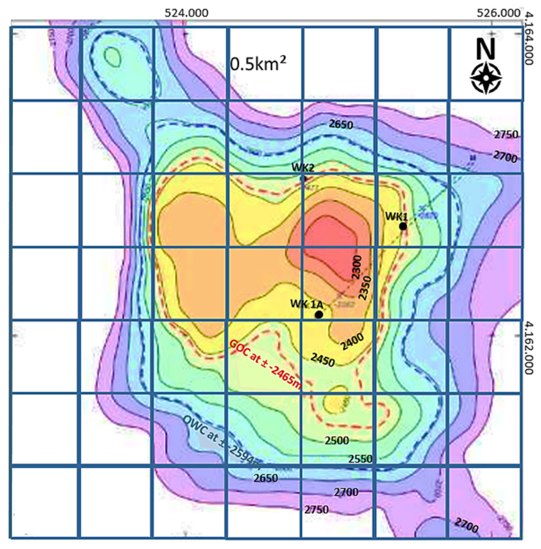
4.2. Gross Rock Volume (GRV)
To proceed with calculations, the
GRV needs to be estimated down to the spill depth. To estimate the
GRV from the crest down to the OWC, the contour map shown in
Figure 3 was utilized. This map was digitized with each square accounting to 0.25 km
2, and their values versus depth are shown in
Figure 4. For the uncertainty in the column height, a probabilistic area distribution factor was incorporated, leading to three column height values
, each taken as equal to the one at which the contour area is 21%, 37% and 64% of the maximum (
). The values obtained (85 m, 120 m and 198 m) correspond to three scenarios (optimistic, expected, pessimistic) known as P10, P50 and P90. In this case, the base area (
) at the OWC is estimated at 3.5 km; hence, the gross volumes are estimated at 0.062, 0.155 and 0.444 km
3, respectively.
Lastly, to account for the non-cuboidal shape of the reservoir, a correction is needed, and this is the geometric factor (
GF). Further reducing the rock volume according to the ratio
between the gross thickness and the obtained column height,
GF equals 6.2%, 15.5% and 44.4% for the examined scenarios, as obtained from its model
. Ultimately, both factors are combined to create the following equation:
to provide gross rock volume estimates of 0.012, 0.039 and 0.155 km
3, respectively. The same process is repeated for any possible spill depths below the OWC.
4.3. Available Pore Volume (PV)
To convert the GRV to the PV available for NG and CO2 storage, estimations of porosity and connate water level are required. Based on the experience obtained in carbonate fields and on the evidence received from the exploration drilling program, porosity is expected to be governed by a triangular distribution with boundary values equal to 8% and 15% and a mode of 10%. Initial water saturation above the OWC is estimated based on analogs and is expected to vary uniformly in (20%, 40%), whereas below the OWC it will be 100%. Finally, the residual oil saturation after water flooding and miscible CO2 injection for such systems is expected to vary, normally settling at around 40% and 20%, respectively.
4.4. PVT Values
To estimate oil and gas volumetric factors black oil correlations were adopted utilizing reservoir temperature and traditional field data input, i.e., tank oil API, tank gas gravity and GOR, out of which only tank oil density is known to be equal to 27 API. To handle uncertainty, three values were realized for each of the unknown parameters. Reservoir temperature was estimated using various geothermal gradients equaling 160, 180 and 210 °F, and gas specific gravity is expected to exhibit values equal to 0.8, 0.9 and 0.95, with the highest value corresponding to the possibility of high H2S content.
As
GOR is not known, the pressure at the GOC was used to correlate since that value is equal to the oil and gas saturation pressure.
Pb varies and is estimated to be equal to 3700, 3750 or 3800 psi due to the uncertainty in the DST measurements. By combining the above to the standing correlation,
GOR is estimated to vary between 830 and 900 scf/stb. By further incorporating the latter in the standing correlation for
Bo, its values are expected to vary between 1.43, 1.53 and 1.57 rb/stb. Of course, pore volume below the OWC only needs a
Bw value, typically set at 1.05 as it is fully filled by water. NG volume factor,
Bg, is estimated by considering its relationship to the compressibility factor, i.e.,:
which is a function of the gas gravity varying between 0.55 (for pure methane) to 0.87 (in the presence of heavier components) with the range between 0.6 and 0.7 being the most common. Under those assumptions and combining pressure and temperature uncertainty,
Z is expected to vary normally between 0.86 and 0.93; therefore,
Bg is expected to vary between 0.0040 and 0.0047 cf/scf. For the case of CO
2, the injected gas will appear in a supercritical state in the reservoir with a density of approximately 900 kg/m
3.
4.5. Injected Gas Storage Capacity
Although the uncertainty incorporated into each variable has been recognized and described numerically, the combination of all those sources needs to be evaluated by means of a Monte Carlo simulation. The results obtained indicate that the pore volume above the OWC available to be filled with NG corresponds to 2.1%, 3.5% and 5.3% of the GRV, for P90, P50 and P10, respectively. For the CO2 case, those figures increase slightly to 3.6%, 5.5% and 8.4%. Similarly, the available pore volume below the OWC corresponds to 8.3%, 11.1% and 14.6% of the GRV for both injected fluids.
Using the above results, a chart of the expected stored gas volume for NG and CO
2 was constructed (
Figure 5). At the maximum studied depth (3700 m), the average scenario, as far as both rock volume and fluid phase behavior are concerned, leads to a NG and CO
2 storage of 32 bcm and 123 MMtn. Even if the spill depth proves to be shallower (i.e., 3000 m), expectations are restricted to 9 bcm and 34 MMtn, respectively, which are still excellent, even if some of the NG would be permanently trapped as cushion gas. Yet, it seems that the storage capacity of gas above the OWC is very low, which is in line with the rather small size of what is today considered as the Katakolo hydrocarbon prospect.
5. Discussion and Conclusions
The overview and re-evaluation of already suggested prospective storage sites in Greece and a few new ones has revealed some key risks and drawbacks of the cases examined. With both reviewed Cenozoic basins having shallow present-day depths, the primary risk would be the potential geo-hazards caused over time by such implementations, mainly due to the induced pressures. Additionally, although the reservoir facies in these basins would have been excellent as oil reservoirs, they are neither likely able to provide adequate capacities nor sealing efficiency from a storage perspective. On the other hand, the scenario of salt caverns could be very promising; yet several parameters should be examined alongside regional stresses, such as the actual volume of the diapir structures.
Considering the Katakolo case study, its structure clearly offers a great capability to store either NG or CO2. Although the reservoir of the West Katakolo field must firstly undergo primary and secondary production for such a scenario to be implemented, its potential needs to be further investigated. It is evident from the above evaluation that one of the dominant questions which needs to be answered thus concerns the openness of the system and its ability to allow water escape and as such, the related spill depth.
Lastly, a serious drawback in such scenarios is transportation infrastructures. NG ought to be transported to such sites in a raw state and be injected after treatment. Yet, neither such transportation nor treatment sites are available in Greece, complicating the overall evaluation. A potential plan for transporting NG from a producing field, either within (i.e., offshore blocks W and SW of Crete) or outside Greece, could provide a plausible scenario.
Author Contributions
Conceptualization, S.B.; methodology, S.B., V.I.M., V.G.; software, V.G.; validation, V.I.M., V.G.; investigation, V.I.M., V.G.; resources, V.I.M.; writing V.I.M., V.G., S.B.; visualization, V.I.M.; funding acquisition, IG-FORTH. All authors have read and agreed to the published version of the manuscript.
Funding
This research received no external funding.
Institutional Review Board Statement
Not applicable.
Informed Consent Statement
Not applicable.
Acknowledgments
The Institute of GeoEnergy (IG)-FORTH acknowledges the continuous support of Hellenic Petroleum under a sponsorship agreement in place.
Conflicts of Interest
The authors declare no conflict of interest.
References
- Metz, B.; Davidson, O.; De Conick, H.; Loos, M.; Meyer, L. IPCC 2005; Cambridge University Press: Cambridge, UK, 2005; p. 431. [Google Scholar]
- Bosshart, N.; Ayash, S.; Azzolina, N.; Peck., W.; Gorecki, C.; Ge, J.; Jiang, T.; Burton-Kelly, M.; Anderson, P.; Dotzenrod, N.; et al. Optimizing and Quantifying CO2 Storage Resource in Saline Formations and Hydrocarbon Reservoirs—Final Report; Energy & Environmental Research Center, University of North Dakota: Grand Forks, ND, USA, 2017. [Google Scholar]
- Shi, J.Q.; Durucan, S. CO2 Storage in Caverns and Mines. Oil Gas Sci. Technol.-Rev. D’ifp Energy Nouv. 2005, 60, 569–571. [Google Scholar] [CrossRef] [Green Version]
- Gammer, D.; Green, A.; Holloway, S.; Smith, G. The Energy Technologies Institute’s UK CO2 Storage Appraisal Project (UKSAP). In Proceedings of the SPE Offshore Europe Oil and Gas Conference and Exhibition, SPE: 148426, Aberdeen, UK, 6–8 September 2011. [Google Scholar]
- Conway, A.; Valvatne, C. The Boulton Field, Block 44/21a, UK North Sea. Geological Society, London. Memoirs 2003, 20, 671–680. [Google Scholar] [CrossRef]
- Da Costa, A.; Da Costa, P.; Udebhulu, O.; Azevedo, R.; Ebecken, N.; Miranda, A.; Eston, S.; De Tomi, G.; Meneghini, J.; Nishimoto, K.; et al. Potential of storing gas with high CO2 content in salt caverns built in ultra-deep water in Brazil. Greenh. Gas Sci. Technol. 2019, 9, 79–94. [Google Scholar] [CrossRef] [Green Version]
- IGRS-IFP. Etude Géologique de l’Epire (Grècenord-Occidentale); Editions Technip: Paris, France, 1966. [Google Scholar]
- Ferriere, J.; Chanier, F.; Reynaud, J.Y.; Pavlopoulos, A.; Ditbanjong, P.; Coutand, I. Evolution of the Mesohellenic Basin (Greece): A synthesis. J. Virtual Explor. 2013, 45, 1–51. [Google Scholar] [CrossRef]
- Vamvaka, A.; Kilias, A.; Mountrakis, D.; Papaoikonomou, J. Geometry and structural evolution of the Mesohellenic Trough (Greece): A new approach. Geol. Soc. Lond. Spec. Publ. 2006, 260, 521–538. [Google Scholar] [CrossRef]
- Kilias, A.; Vamvaka, A.; Falalakis, G.; Sfeikos, A.; Papadimitriou, E.; Gkarlaouni, C.; Karakostas, B. The Mesohellenic trough and the Thrace Basin. Two Tertiary molassic Basins in Hellenides: Do they really correlate? Bull. Geol. Soc. Greece 2017, 47, 551–562. [Google Scholar] [CrossRef] [Green Version]
- Soliman, H.A.; Zygogiannis, N. Geological and paleontological studies in the Mesohellenic Basin, Northern Greece. Inst. Geol. Min. Expl. Athens, Geol. And Geoph. Res. 1980, 22, 1–66. [Google Scholar]
- Zygogiannis, N.; Muller, C. Nannoplankton-Biostratigraphie der tertiären Meso-hellenischen Molasse (Nordwest-Griechenland). Z. Der Dtsch. Geol. Ges. 1982, 133, 445–455. [Google Scholar]
- Barbiery, R. Foraminifera of the Eptahori Formation (early Oligocene) of the Mesohellenic basin, northern Greece. J. Micro-Palaeontol. 1992, 11, 73–84. [Google Scholar]
- Zelilidis, A.; Piper, D.; Kontopoulos, N. Sedimentation and basin evolution of the Oligocene–Miocene Mesohellenic basin, Greece. Am. Assoc. Pet. Geol. Bull. 2002, 86, 161–182. [Google Scholar]
- Tasianas, A.; Koukouzas, N. CO2 Storage Capacity Estimate in the Lithology of the Mesohellenic Trough, Greece. Energy Procedia 2016, 86, 334–341. [Google Scholar] [CrossRef] [Green Version]
- Arvanitis, A.; Koutsovitis, P.; Koukouzas, N.; Tyrologou, P.; Karapanos, D.; Karkalis, C.; Pomonis, P. Potential Sites for Underground Energy and CO2 Storage in Greece: A Geological and Petrological Approach. Energies 2020, 13, 2707. [Google Scholar] [CrossRef]
- Kontopoulos, N.; Fokianou, T.; Zelilidis, A.; Alexiadis, C.; Rigakis, N. Hydrocarbon potential of the middle Eocene-middle Miocene Mesohellenic piggy-back basin (central Greece): A case study. Mar. Pet. Geol. 1999, 16, 811–824. [Google Scholar] [CrossRef]
- Koukouzas, N.; Tyrologou, P.; Karapanos, D.; Carneiro, J.; Pereira, P.; de Mesquita Lobo Veloso, F.; Koutsovitis, P.; Karkalis, C.; Manoukian, E.; Karametou, R. Carbon Capture, Utilisation and Storage as a Defense Tool against Climate Change: Current Developments in West Macedonia (Greece). Energies 2021, 14, 3321. [Google Scholar] [CrossRef]
- Koukouzas, N.; Tasianas, A.; Gemeni, V.; Alexopoulos, D.; Vasilatos, C. Geological modelling for investigating CO2 emissions in Florina basin, Greece. Open Geosci. 2015, 7, 20150039. [Google Scholar] [CrossRef]
- Nikolaou, K.; Panagopoulos, G. West Katakolo Field Development: A unique analogue for Western Greece. In Proceedings of the 3rd IENE Workshop, Athens, Greece, 13 November 2018. [Google Scholar]
| Publisher’s Note: MDPI stays neutral with regard to jurisdictional claims in published maps and institutional affiliations. |
© 2022 by the authors. Licensee MDPI, Basel, Switzerland. This article is an open access article distributed under the terms and conditions of the Creative Commons Attribution (CC BY) license (https://creativecommons.org/licenses/by/4.0/).


