Proceeding Paper

Derivation of Appropriate Conditions for Additive Manufacturing Technology Using Hot-Wire Laser Method †

1
Graduate School of Engineering, Hiroshima University, Higashihiroshima 739-0046, Japan
2
Matsumoto Kikai Co., LTD, Osaka 581-0092, Japan
3
Marubun Corp., Tokyo 103-8577, Japan
*
Authors to whom correspondence should be addressed.
Presented at the 1st International Electronic Conference on Metallurgy and Metals, 22 February–7 March 2021; Available online: https://iec2m.sciforum.net/.
Mater. Proc. 2021, 3(1), 9; https://doi.org/10.3390/IEC2M-09244
Published: 18 February 2021
(This article belongs to the Proceedings of The 1st International Electronic Conference on Metallurgy and Metals)

Abstract

:
The aim of this research was to develop a high-efficiency and high-material-use additive manufacturing technology using the hot-wire laser method. In this study, the optimization of process conditions using a combination of a high-power diode laser with a relatively large rectangular laser spot and a hot-wire system was investigated. The effects of process parameters such as laser power, process speed, and wire feeding rate (wire feeding speed/process speed) on a bead appearance and cross-sectional characteristics (e.g., effective width, effective height, maximum height, and near net shape rate) were studied in detail. The process phenomena during the multi-layer deposition were investigated by in situ observation via a high-speed camera.

1. Introduction

In recent years, research, developments, and practical applications of additive manufacturing (AM) technologies such as three-dimensional (3D) printing processes have been actively carried out [1,2,3,4,5,6]. As opposed to traditional subtractive manufacturing methodologies, AM technology is to continuously accumulate materials by adding layer-by-layer and complete the 3D parts through computer-controlled technology [7,8,9,10].
In a recent study, the AM technology can be categorized into three types in terms of heat sources: wire and arc additive manufacturing (WAAM), electron beam additive manufacturing (EBAM), and laser additive manufacturing (LAM). Although the WAAM technology has convenient and economical efficient advantages compared with other AM technology, it has the problems of high dilution, distortion, and small tolerances of process conditions [11,12]. The EBAM technology also has some problems such as the high cost of equipment and the vacuum precision welding environment [13,14]. The LAM technology using powder materials has an advantage of high precision while a lot of problems, such as a low deposition rate and higher material cost [15,16]. Moreover, about a small amount of (20%) of the metal powder could be effectively used, while the metal wire can greatly improve the use rate of the material [17]. Hence, the deposited material is prefabricated as metal wire instead of metal powder. However, due to the low laser absorption of cold-wire, the process using cold-wire materials also has a lot of problems, such as spatter and fume generations, difficulties of heat input control and wire melting, small tolerances of process conditions, and so on [18,19].
The laser hot-wire (LHW) is a novel welding process which has dual heat sources. A convertible laser beam serves as the main heat source, and the additional heat source is Joule heat generated via the current, which heated the filler cold-wire to its melting point during the deposition. The advantage of the laser hot-wire method can effectively increase productivity, and the degree of freedom of control of the material is high. Compare with the cold-wire laser method, this method has high material use and forms a model with a wider range of bead width at a high deposition rate [20,21]. Therefore, the development of laser hot-wire AM technology is very meaningful and valuable.
In this research, the high-efficiency AM technology using a combination of a high-power diode laser with a relatively large laser spot a hot-wire system is studied. The effect of process parameters (Laser power, process speed, and wire feeding rate) on the melting phenomenon was systematically studied. Moreover, the effects of process parameters (laser power, process speed, wire feeding rate) on the bead appearance and cross-section characteristics were also investigated. In this paper, we report the results of the derivation of appropriate process conditions to achieve higher efficiency, sound shape, and 15-layer large-scale wall modeling.

2. Materials and Experimental Methods

The Z3321-YS308L with a 1.2-mm diameter was used as a filler material. A 590 MPa-class steel plate with 9-mm thickness was used as a base metal. Table 1 shows the process conditions and Figure 1 shows the experimental set-up. The wide and narrow (1.6 × 11 mm) rectangular laser spot was applied. The laser power, process speed, and wire feeding rate (wire feeding rate: wire feeding speed/process speed) were varied as a parameter respectively. Ar gas was used for shielding with a shielding box. The bead appearance evaluation, the cross-sectional observation, and measurement of bead sizes were performed. The effective width, effective height, maximum height, and near net shape rate were measured on three cross-sections for each bead as shown in Figure 2.

3. Results

Figure 3 shows the evaluated result of bead appearance on the three-layer deposition for each combination of process conditions; (a) process speed and laser power, (b) wire feeding rate laser power. It can be seen from Figure 3a that when the wire feed rate is fixed, each process speed has a limitation of the lowest laser power. In other words, when the energy heat input (see in Equation (1)) is below a certain limit, defects will appear on the bead surface. Moreover, it can be concluded from Figure 3b that when the process speed is fixed, the laser hot-wire method can achieve a wide range of process conditions deposition, but each wire feeding rate has a limitation of the lowest energy heat input. It is concluded that the bead with some typical defects such as wire stubbing (denoted by ×) was obtained at relatively low laser power under different process speed and wire feeding rate. In contrast, sound bead with no defects (denoted by o) was obtained at relatively high laser power under proper process speed of 0.3–0.5 m/min and wire feeding rate of 20–40.
Figure 4 shows the evaluated results of bead shape when the process speed was varied at a constant wire feeding rate of 20, 30, and a constant laser power of 5.5 kW. It is observed that the effective width decreases, the effective height, and maximum height increase, the near net shape rate increases with the increase of the process speed. All measured values of the wire feeding speed of 30 improve compared with the values of the wire feeding speed of 20. In other words, the feeding rate of 20 could not supply enough volume of deposit metal for the wide laser spot of 11 mm on the proposed high-efficiency AM process.
Figure 5 shows the evaluated results of bead shape and Figure 6 shows the cross-sections when the wire feeding rate was varied around 30 under the constant laser power of 5.5 kW and a constant process speed of 0.36 m/min. It is found that the effective bead width over 10 mm for the laser spot width of 11 mm, effective height almost 9 mm, maximum height almost 11 mm, and near net shape rate of 80% could be obtained under the wire feeding rate of 33.3.
Figure 7 shows the bead appearance and cross-sectional observation of 15-layer sample using the optimum conditions obtained from the above investigations. It is observed that the smooth and sound bead could be obtained even if all process conditions are fixed from the 1st layer to final the 15th layer. Moreover, the effective height over 50 mm, maximum height over 55 mm, effective width over 8 mm, and near net shape rate of 83% could be obtained with very high efficiency using only 15 layers.

4. Discussion

4.1. Three-Layer Deposition

Figure 8a–d show the bead appearance and high-speed camera images of the three-layer deposition under different process speed and laser power combinations. When a process speed (Vp) of 0.3 m/min, laser power (P) of 4 kW, and wire feeding rate (WFR) of 20, the sound bead with no defects was obtained. As shown in Figure 8a, the filler wire melted continuously at a low process speed. When a higher process speed (0.4, 0.5 m/min) was applied when the wire feeding rate kept constant, the bead with typical defects was obtained (see in Figure 8b,d). The energy heat input decreases with the increase in process speed, the insufficient energy heat input which resulted in the filler wire cannot melt completely and attributes to the misalignment between the filler wire and molten pool, then forming the spikes during the deposition. In other words, at a relatively low energy heat input, it will result in a shallower weld penetration in the previous layer, the filler wire cannot be feeding smoothly and continuously. When a process speed of 0.4 m/min, laser power increased to 5 kW, as shown in Figure 8c, the filler wire feeding continuously into the molten pool area and the sound bead was formed. It is concluded that increasing the laser power can have enough energy heat input to generate deep weld penetration for the previous layer to ensure that the filler wire can be fully melted.
Figure 9a–d show the bead appearance and high-speed camera images of the three-layer deposition under different wire feeding rate and laser power combinations. As shown in Figure 9a, when a suitable wire feeding rate for a fixed combination of laser power and process speed, what produced a stable welding process and a sound bead (see in Figure 9a,c). When the wire feeding rate (30, 40) was excessively high for a fixed combination of laser power and process speed (see in Figure 9b,d), the filler wire interacted momently with the laser irradiation, results in the unmelt and nearly solid filler wire collide with the bottom of the substrate. A misalignment between the filler wire and molten pool caused the filler wire to slip out of the molten pool. In this process, the irregular bead with typical defects was obtained.
To combine the process parameters of laser power, process speed, laser spot size, and wire feeding speed, the evaluation of the energy heat input (J/mm3) and wire feeding rate were shown in Equations (1) and (2). P is the laser power, in W; As is the area of laser spot size, in mm; Vp is the process speed, in m/min; Vf is wire feeding speed, in m/min.
Energy   heat   input = P A s V p
Wire   feeding   rate = V f V p
Figure 10 shows the bead evaluation map produced at each process condition depended on the energy heat input (Y-axis) and wire feeding rate (X-axis). It can be observed that bead with typical defects area region increases with the increase of wire feeding rate, and decreases with the increase of energy heat input. This confirms the fact that the defects can be eliminated by either increasing the energy heat input or decreasing the wire feeding rate.

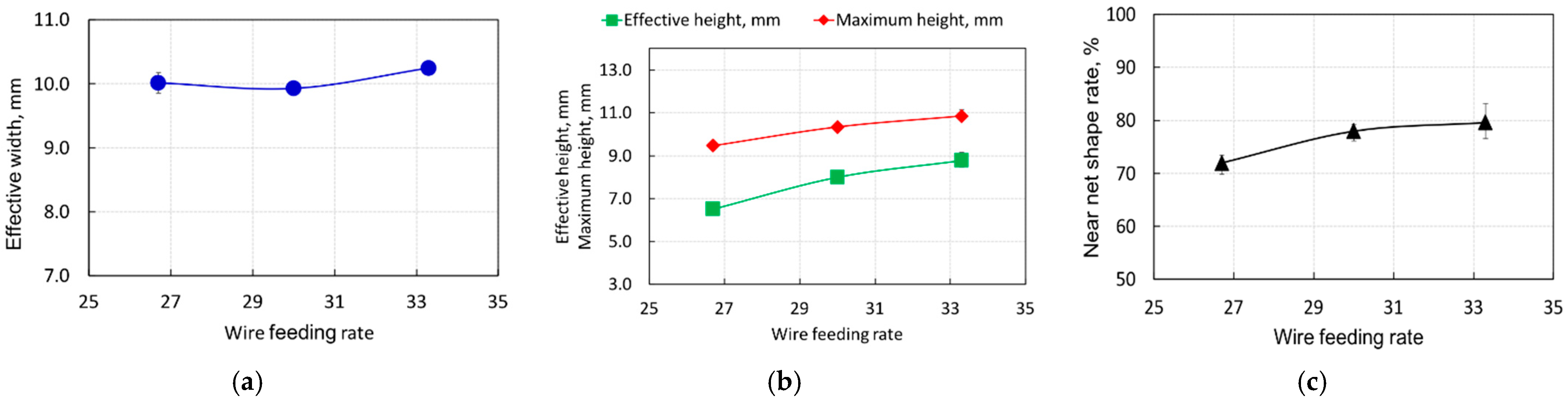
4.2. Effects of Process Parameters on Cross-Sectional Characteristics

The cross-sectional characteristics (e.g., effective width, effective height, maximum height, and near net shape rate) mainly influenced by the process speed when the other process parameters were fixed (see in Figure 4). The effective width decreases, the effective height, maximum height, and the near net shape rate increase with the increases of the process speed. This result is attributed to the increased process speed produced lower the energy heat input, hence a smaller size of the substrate was melted, and a smaller bead was formed under high process speed. In other words, increasing the processing speed means that the energy heat input is reduced, so that the width of the substrate and the previous layer will be narrowed. Meanwhile, the amount of wire fed per unit time is constant, the width of the deposited layer will inevitably decrease results in the height of each layer increases.
Wire feeding rate is another important process parameter. When the laser power and welding speed are fixed, it means that the energy heat input is constant, so the change in the width of the bead is not obvious. In additions, the increase in wire feeding rate increased the effective height and maximum height (see in Figure 5). This may be due to the wire feeding rate increased, more filler materials were deposited onto the molten pool producing and the height increase significantly. Hence, a thicker three-layer deposition can be obtained under a higher wire feeding rate.

5. Conclusions

Stable deposition phenomena and the sound bead could be obtained even when the process conditions are greatly changed, and the degree of freedom in selecting the process conditions is very high by using a combination of a high-power diode laser with a relatively large laser spot a hot-wire system. The smooth and sound bead could be obtained even if all process conditions are fixed from the 1st layer to the 15th layer. Large-scale wall modeling of more than 50 mm in height, 8 mm in width, and 250 mm in length could be fabricated efficiently and stably by using the laser hot-wire AM technology.

Author Contributions

Conceptualization, S.Z. and M.Y.; methodology, S.Z. and M.Y.; investigation, S.Z. and Y.N.; data curation, S.Z.; writing-original draft preparation, S.Z; writing-review and editing, S.Z. and M.Y.; supervision, H.A., R.E., and M.Y. All authors have read and agreed to the published version of the manuscript.

Institutional Review Board Statement

Not applicable.

Informed Consent Statement

Not applicable.

Data Availability Statement

Not applicable.

Conflicts of Interest

The authors declare no conflict of interest.

References

  1. DebRoy, T.; Wei, H.L.; Zuback, J.S.; Mukherjee, T.; Elmer, J.W.; Milewski, J.O.; Beese, A.M.; Wilson-Heid, A.; De, A.; Zhang, W. Additive manufacturing of metallic components—Process, structure and properties. Prog. Mater. Sci. 2018, 92, 112–224. [Google Scholar] [CrossRef]
  2. Milewski, J.O. Additive Manufacturing of Metals; Springer Series in Materials Science; Springer: Berlin/Heidelberg, Germany, 2017; Volume 258, pp. 7–33. [Google Scholar]
  3. Cawley, J.D. Solid freeform fabrication of ceramics. Curr. Opin. Solid State Mater. Sci. 1999, 4, 483–489. [Google Scholar] [CrossRef]
  4. Sandeep, D.C. Comparison and analysis of different 3D printing techniques. Int. J. Eng. Technol. 2017, 8, 264–272. [Google Scholar]
  5. Syed, A.M.T.; Elias, P.K.; Amit, B.; Susmita, B.; Lisa, O.; Costas, C. Additive manufacturing: Scientific and technological challenges, market uptake and opportunities. Mater. Today 2018, 21, 22–37. [Google Scholar]
  6. Frazier, W.E. Metal Additive Manufacturing: A Review. J. Mater. Eng. Perform. 2014, 23, 1917–1928. [Google Scholar] [CrossRef]
  7. Schultz, V.; Seefeld, T.; Vollertsen, F. Gap bridging ability in laser beam welding of thin aluminum sheets. Phys. Procedia 2014, 56, 545–553. [Google Scholar] [CrossRef]
  8. Singh, R.; Gupta, A.; Tripathi, O.; Srivastava, S.; Singh, B.; Awasthi, A.; Rajput, S.K.; Sonia, P.; Singhal, P.; Saxena, K.K. Powder bed fusion process in additive manufacturing: An overview. Mater. Today 2020, 26, 3058–3070. [Google Scholar] [CrossRef]
  9. Bandyopadhyay, A.; Bose, S. Additive Manufacturing, 1st ed.; CRC Press: Boca Raton, FL, USA, 2015; pp. 2–24. [Google Scholar]
  10. Gibson, I.; Rosen, D.W.; Stucker, B. Additive Manufacturing Technologies: 3D Printing, Rapid Prototyping, and Direct Digital Manufacturing; Springer: New York, NY, USA, 2009; pp. 4–38. [Google Scholar]
  11. Joshi, S.C.; Sheikh, A.A. 3D printing in aerospace and its long-term sustainability. Virtual Phys. Prototyp. 2015, 10, 175–185. [Google Scholar] [CrossRef]
  12. Nie, Z.G.; Wang, G.; McGuffin-Cawley, J.D.; Narayanan, B.; Zhang, S.J.; Schwam, D.; Kottman, M.; Rong, Y.M. Experimental study and modeling of H13 steel deposition using laser hot-wire additive manufacturing. J. Mater. Process. Technol. 2016, 235, 171–186. [Google Scholar] [CrossRef]
  13. Yan, W.Z.; Yue, Z.F.; Zhang, J.Z. Study on the residual stress and warping of stiffened panel produced by electron beam freeform fabrication. Mater. Des. 2016, 89, 1205–1212. [Google Scholar] [CrossRef]
  14. Chang, S.H.; Gach, S.; Senger, A.; Zhang, H.Y.; Du, D. A new 3D printing method based on non-vacuum electron beam technology. J. Phys. Conf. Ser. 2018, 1074, 012017. [Google Scholar] [CrossRef]
  15. Chlebus, E.; Gruber, K.; Kuźnicka, B.; Kurzac, J.; Kurzynowski, T. Effect of heat treatment on the microstructure and mechanical properties of Inconel 718 processed by selective laser melting. Mater. Sci. Eng. 2015, 639, 647–655. [Google Scholar] [CrossRef]
  16. Criales, L.E.; Arisoy, Y.M.; Lane, B.; Moylan, S.; Donmez, A.; Ozel, T. Laser powder bed fusion of nickel alloy 625: Experimental investigations of effects of process parameters on melt pool size and shape with spatter analysis. Int. J. Mach. Tools Manuf. 2017, 121, 22–36. [Google Scholar] [CrossRef]
  17. Ma, M.M.; Wang, Z.M.; Wang, D.Z.; Zeng, X.Y. Control of shape and performance for direct laser fabrication of precision large-scale metal parts with 316L Stainless Steel. Opt. Laser Technol. 2013, 45, 209–216. [Google Scholar] [CrossRef]
  18. Yang, D.X.; Li, X.Y.; He, D.Y.; Nie, Z.R.; Huang, H. Optimization of weld bead geometry in laser welding with filler wire process using Taguchi’s approach. Opt. Laser Technol. 2012, 44, 2020–2025. [Google Scholar]
  19. Du, F.R.; Zhu, J.Q.; Ding, X.P.; Zhang, Q.; Ma, H.L.; Yang, J.; Cao, H.Z.; Ling, Z.M.; Wang, G.Y.; Duan, X.M.; et al. Dimensional characteristics of Ti-6Al-4V thin-walled parts prepared by wire-based multi-laser additive manufacturing in vacuum. Rapid Prototyp. J. 2019, 25, 849–856. [Google Scholar] [CrossRef]
  20. Yamamoto, M.; Shinozaki, K.; Kadoi, K.; Fujita, D.; Inoue, T.; Fukahori, M.; Kitahara, Y. Development of Hot-wire Laser Welding Method for Lap Joint of Steel Sheet with Wide Gap. Q. J. Jpn. Weld. Soc. 2011, 29, 58–61. [Google Scholar] [CrossRef]
  21. Kadoi, K.; Shinozaki, K.; Yamamoto, M.; Owaki, K.; Inose, K.; Takayanagi, D. Development of High-efficiency/High-quality Hot-wire Laser Fillet Welding Process. Q. J. Jpn. Weld. Soc. 2011, 29, 62–65. [Google Scholar] [CrossRef]
Figure 1. Experimental set-up.
Materproc 03 00009 g001
Figure 2. Cross-sectional evaluation.
Materproc 03 00009 g002
Figure 3. The bead evaluation of three-layer for each combination of process parameters: (a) Process speed and laser power; (b) Wire feeding rate and laser power.
Materproc 03 00009 g003
Figure 4. Bead shape evaluation (P = 5.5 kW): (a) Effective width; (b) Effective height and Maximum height; (c) Near net shape rate.
Materproc 03 00009 g004
Figure 5. Bead shape evaluation (P = 5.5 kW, Vp = 0.36 m/min): (a) Effective width; (b) Effective height and Maximum height; (c) Near net shape rate.
Materproc 03 00009 g005
Figure 6. Cross-sections.
Materproc 03 00009 g006
Figure 7. Bead appearance and cross-sectional observation (15-layer).
Materproc 03 00009 g007
Figure 8. Melting phenomenon for varied as process speed and laser power: (a) P = 4 kW, Vp = 0.3 m/min; (b) P = 4 kW, Vp = 0.4 m/min; (c) P = 5 kW, Vp = 0.4 m/min; (d) P = 5 kW, Vp = 0.5 m/min.
Materproc 03 00009 g008
Figure 9. Melting phenomenon for varied as wire feeding rate and laser power: (a) P = 3.3 kW, WFR = 20; (b) P = 3.3 kW, WFR = 30; (c) P = 4.5 kW, WFR = 30; (d) P = 4.5 kW, WFR = 40.
Materproc 03 00009 g009
Figure 10. The map illustrating the three-layer deposition.
Materproc 03 00009 g010
Table 1. Process conditions.
ContentValue
Number of layers3
Laser power, kW3.3~5.5
Laser irradiation angle, deg5
Laser spot size, mm1.6 × 11
Process speed, m/min0.24~0.5
Wire feeding speed, m/min6~20
Wire feeding rate20~40
Wire feeding angle, deg45
Shielding gas (Ar), L/min30
Publisher’s Note: MDPI stays neutral with regard to jurisdictional claims in published maps and institutional affiliations.

