Proceeding Paper

Impact Test Applications Supported by FEA Models in Surface Engineering for Coating Characterization †

by
Georgios Skordaris
1,*,
Antonios Bouzakis
2 and
Konstantinos-Dionysios Bouzakis
1,3
1
Laboratory for Machine Tools and Manufacturing Engineering, Mechanical Engineering Department, Aristotle University of Thessaloniki, 54124 Thessaloniki, Greece
2
Impact–BZ Ltd., London SW11 5QL, UK
3
Turkish-German University in Istanbul, 34820 Beykoz/İstanbul, Turkey
*
Author to whom correspondence should be addressed.
Presented at the 2nd Coatings and Interfaces Web Conference, 15–31 May 2020; Available online: https://ciwc2020.sciforum.net/.
Mater. Proc. 2020, 2(1), 13; https://doi.org/10.3390/CIWC2020-06809
Published: 30 April 2020
(This article belongs to the Proceedings of 2nd Coatings and Interfaces Web Conference (CIWC-2 2020))

Abstract

:
The impact test has been used for several years, among others, for characterizing the fatigue strength, creep, adhesion and residual stresses of coatings at ambient and elevated temperatures under dry or lubricated conditions. A major advantage of this test method is that in many cases, it can be employed directly on the coated parts and not on specimens. The obtained experimental results are evaluated by convenient finite element method (FEM)-supported algorithms. Based on these algorithms, critical data for predicting the life span of coated parts such as cutting tools and bearings and for planning appropriate replacements can be obtained. The paper provides an overview of the development of impact test devices, experimental techniques and result evaluation methods. Characteristic examples highlighting the quantification of the fatigue strength of PVD (Phyical Vapour Deposition) coatings and their adhesion via the critical equivalent and shear stresses, respectively, as well as that of the temperature-dependent interfacial fatigue strength of diamond coatings via the critical shear stress, are shown.

1. Introduction

The surface properties of machine parts and elements strongly affect their operational reliability [1,2,3]. Therefore, methods to determine superficial material data after the final surface treatments are pivotal, since they facilitate the checking of the convergence to prescribed surface specifications required for the fulfillment of technical requirements [4,5,6]. Hereupon, the fatigue endurance of repetitively loaded surfaces is a significant property. To assess this property, the related surfaces must be loaded periodically under conditions similar to the parts’ real operation. The surface response and wear during such a test must be monitored and appropriately analyzed for attaining characteristic material data related to the fatigue strength, residual stresses, adhesion (in the case of coated surfaces) etc.
The surface responses of various materials can be investigated at various repetitive loads and impact times using impact test devices, as presented in the literature [4,7,8]. Using an electro-dynamic impact tester, impact times less than 1 ms can be realized [7]. Furthermore, via a piezoelectric one, impact times longer than 1 ms can be adjusted [8]. Figure 1 illustrates the impact tester and the related fixtures for conducting perpendicular and inclined impact tests. This device was manufactured by the company Impact-BZ (London, UK) [9] in conjunction with the Laboratory for Machine Tools and Manufacturing Engineering of the Aristotle University of Thessaloniki. A ceramic ball of 5 mm diameter repetitively penetrated into the specimen under an adjustable maximum load. With the aid of a proportional, integral and differential (PID) controller, the output voltage of a variable transformer, through a direct current (DC) motor, was adjusted to attain constant impact force peaks throughout the entire test duration. Moreover, measurements of current, forces, temperatures and further process parameters were conducted and monitored. Employing this impact tester, various coatings’ properties at ambient or elevated temperatures can be characterized, and related material data, defined. In the next sections, relevant application examples will be presented as well as finite element method (FEM)-supported procedures for evaluating the results and determining data such as the fatigue endurance stress and coating adhesion of PVD as well as those of diamond coatings.

2. PVD Coating’s Fatigue Strength and Adhesion
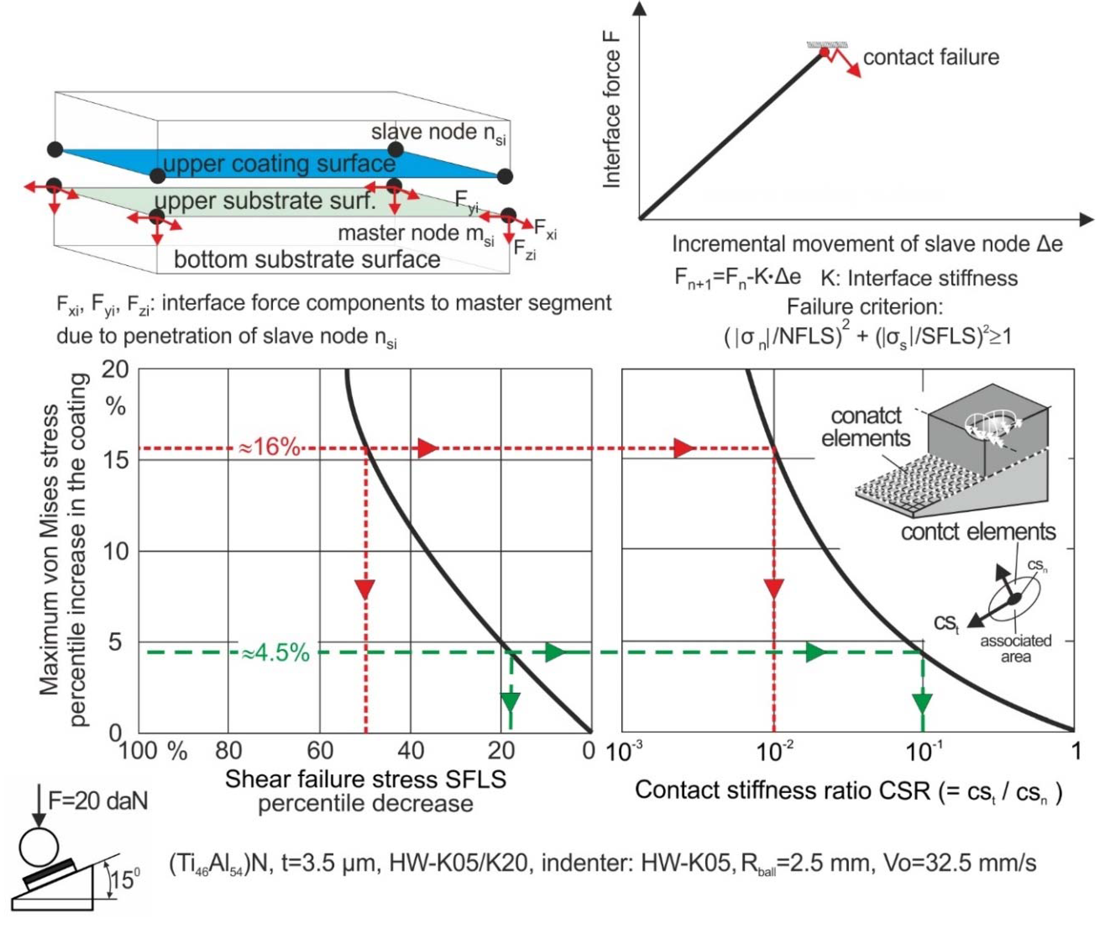
2.1. Methodology

During the impact test, a ball indenter periodically penetrated the coating under a desired maximum load. Depending on the impact load and on the number of impacts, a coating failure could occur. The perpendicular impact tests were aimed at detecting the maximum impact force Fmax (fatigue threshold force) that the coating could withstand without failure. With the aid of a FEM simulation of the impact test, the maximum equivalent stress developed in the coating at the fatigue threshold force Fmax during its loading and the remaining one due to the substrate plastic deformation was calculated. Based on these data, the Smith-like diagram illustrated in Figure 2 was established [4]. Via this diagram, the coating fatigue endurance stress SD for repetitive loads from zero up to a certain maximum value was determined. Considering SD, the Woehler-like diagram demonstrated in the middle of Figure 2 was created. The data employed for establishing the aforementioned graphs did not depend on the coating adhesion, since the film was only vertically loaded during the perpendicular impact test.
The film adhesion could be characterized by an inclined impact test [10]. The oblique loading direction during the inclined impact test induced shear stresses into the film, which, in the case of poor adhesion, led to coating material overloading and to its accelerated failure [10]. This test also rendered possible the PVD film adhesion quantification in terms of the tangential-to-normal film–substrate interface stiffness (CSR ratio). A CSR equal to 1 means that the film adhesion is ideal. In this context, employing a FEA (Finite Element Analysis) model of the inclined impact test at an inclination angle θ, the coating maximum stress SF induced by a force F was calculated. In these calculations, an ideal adhesion (CSR = 1) was assumed. If the film–substrate adhesion was not ideal (CSR < 1), the coating strains were higher than those in the developed ones at the same load in the case of ideal adhesion. Hence, the actual coating stress S*eqv was larger than SF, thus leading to film fatigue failure at a smaller number of impacts NI* than the expected NIF according to the established Woehler diagram (see Figure 2). The parameter NI* was experimentally determined by conducting inclined impact tests. The Woehler diagram was employed, since due to the enhanced strength properties of the cemented carbide and the lower loads applied in the inclined impact test, the substrate plastic deformation was negligible, as were the remaining stresses. If this was not valid, as, for example, in the case of softer substrates, the methods described in the publication [11] were used. Finally, using FEM-supported calculations in the third procedure stage, the maximum equivalent stress Seqvi max developed at a force F and constant inclination angle θ was determined as a function of the CSR metric (see the graph at the bottom of Figure 2). Using the latter graph, taking into account the determined actual coating stress S*eqv, the CSR of the tested coating was graphically defined [12].

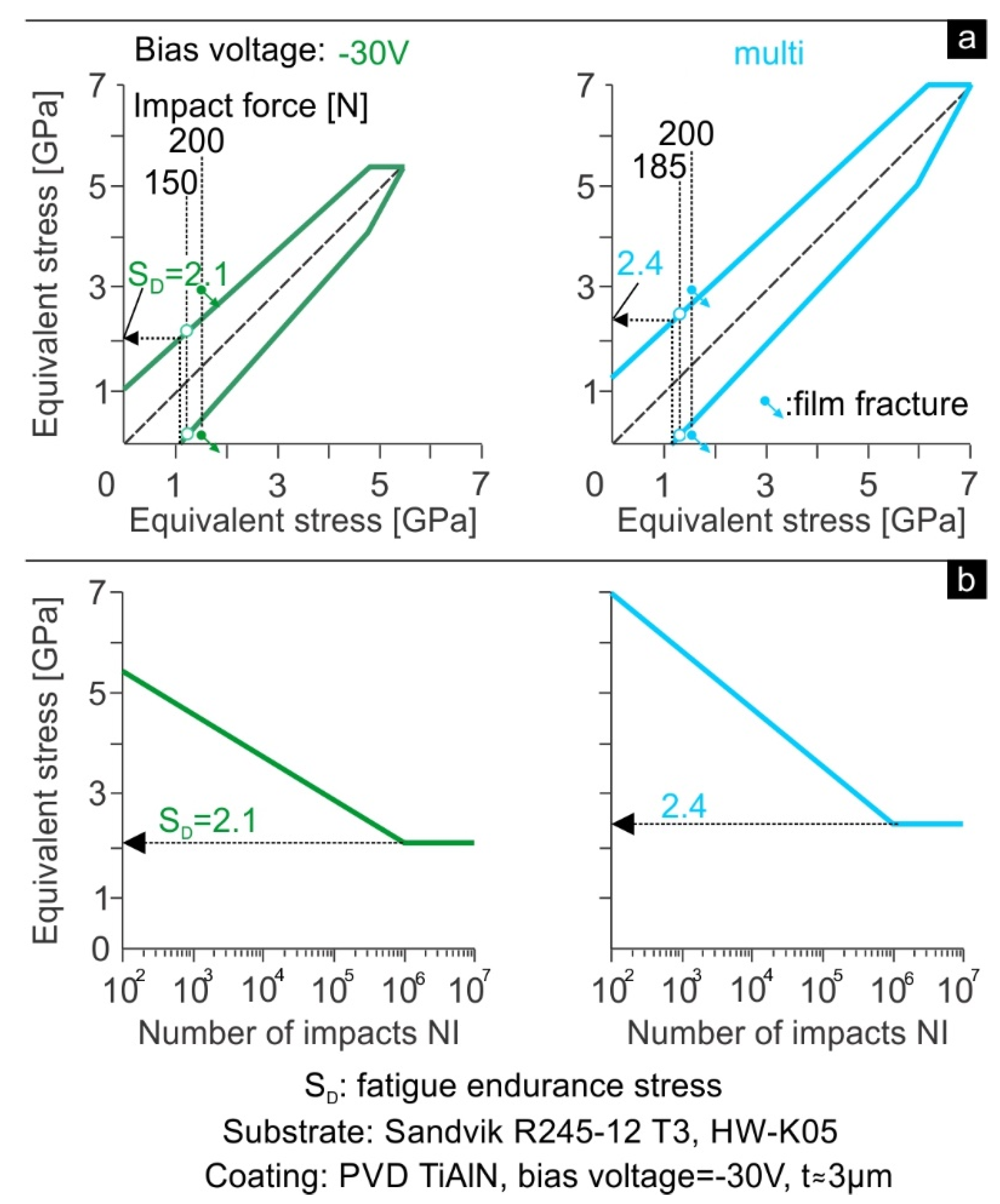
2.2. Characteristic Examples

An example of the coating failure evolution during the perpendicular impact test is demonstrated in Figure 3 [12]. In this example, the applied impact load imposed maximum equivalent stresses during the loading and relaxation outside of the fatigue safe area of the film Smith-like diagram shown in Figure 3, thus causing a film fatigue fracture. The latter diagram schematically presented in Figure 2 (see procedure stage I) is further described in the following section. For capturing the remaining imprint depth RID, sections in the middle of the impact imprint were analyzed using confocal microscopy. After 104 impacts, the RID was approximately 0.2 μm. This corresponds roughly to the substrate plastic deformation induced by the applied impact load of 300 N. At 106 impacts, due to the progressive crack propagation and the occurring film micro-damages and removal, an imprint depth of roughly 3.2 μm developed. This is larger than the film thickness, and thus, the substrate was revealed.
Using the FEM-supported simulation of the impact test mentioned in Figure 2 [12], the maximum equivalent stress during the impact test loading and relaxation at the force of 200 N and at the fatigue threshold loads of the PVD TiALN coatings deposited at various bias voltages were calculated. Based on these data, as schematically depicted in Figure 2, the Smith-like diagrams demonstrated in Figure 4a were established for the investigated coatings. Employing the latter graphs, the coating’s fatigue endurance stresses SD for repetitive loading from zero to a maximum value were defined. Considering these stresses, the Woehler-like diagrams of the investigated coatings shown in Figure 4b were established. These results show that the bias voltage augmentation increased the coating’s fatigue endurance stresses.
Moreover, inclined impact tests were conducted for evaluating the adhesion of the aforementioned coatings [12]. To reduce the inclined impact test duration and simultaneously achieve film removal rates enabling the efficient monitoring of the coating damage evolution, the impact load F and the inclination angle θ were adjusted to 90 N and 15°, respectively. The developed coating failure depth (CFD) versus the number of impacts on the coatings prepared at various bias voltages are presented in Figure 5a. The criterion for the coating fracture start was a coating failure depth CFD equal to 0.5 μm. Under the applied inclined impact test conditions, if the film deposited at −30 V had an ideal adhesion (CSR = 1), the maximum equivalent stress in the coating would be approximately 2 GPa according to conducted FEM-supported calculations. Since this stress is less than the corresponding fatigue endurance of one of these coatings, amounting to 2.1 GPa, no film fatigue fracture after one million repetitive impacts would appear. However, because the film adhesion was not ideal (CSR < 1) in the film case of the −30 V bias voltage, the coating fatigue fracture started after approximately 4.5 × 10⁵ impacts (NI*), whereas with a multi-bias voltage, it began after roughly NI* 1.3 × 10⁵ impacts (see Figure 5a). For determining the actual CSRs of the investigated films, the procedure stage III clarified in Figure 2 was employed. More specifically, at the applied impact force of 90 N and inclination angle of 15°, the resulting maximum film equivalent stress S*eqv versus CSR was described as a function of CSR as illustrated in the right-hand graphs of Figure 5b. The numbers of impacts NI* associated with the coating fatigue fracture initiation were introduced in the corresponding Woelher-like diagrams exhibited in the right of Figure 5b, and the corresponding S*eqv stresses were defined. Considering these stresses, as depicted in this figure, the related CSRs were defined, amounting to 0.05 and 0.004 in the cases of −30 V and multi-bias voltage, respectively. The attained results indicate that coatings deposited at higher bias voltages are associated with a significant CSR decrease. In this way, coatings deposited at the bias voltage of −30 V, although they possess lower fatigue strength than those ones deposited at multi-bias voltage, demonstrate comparably better performance in the inclined impact tests. This fact can be explained considering the adhesion deterioration when increasing the bias voltage.

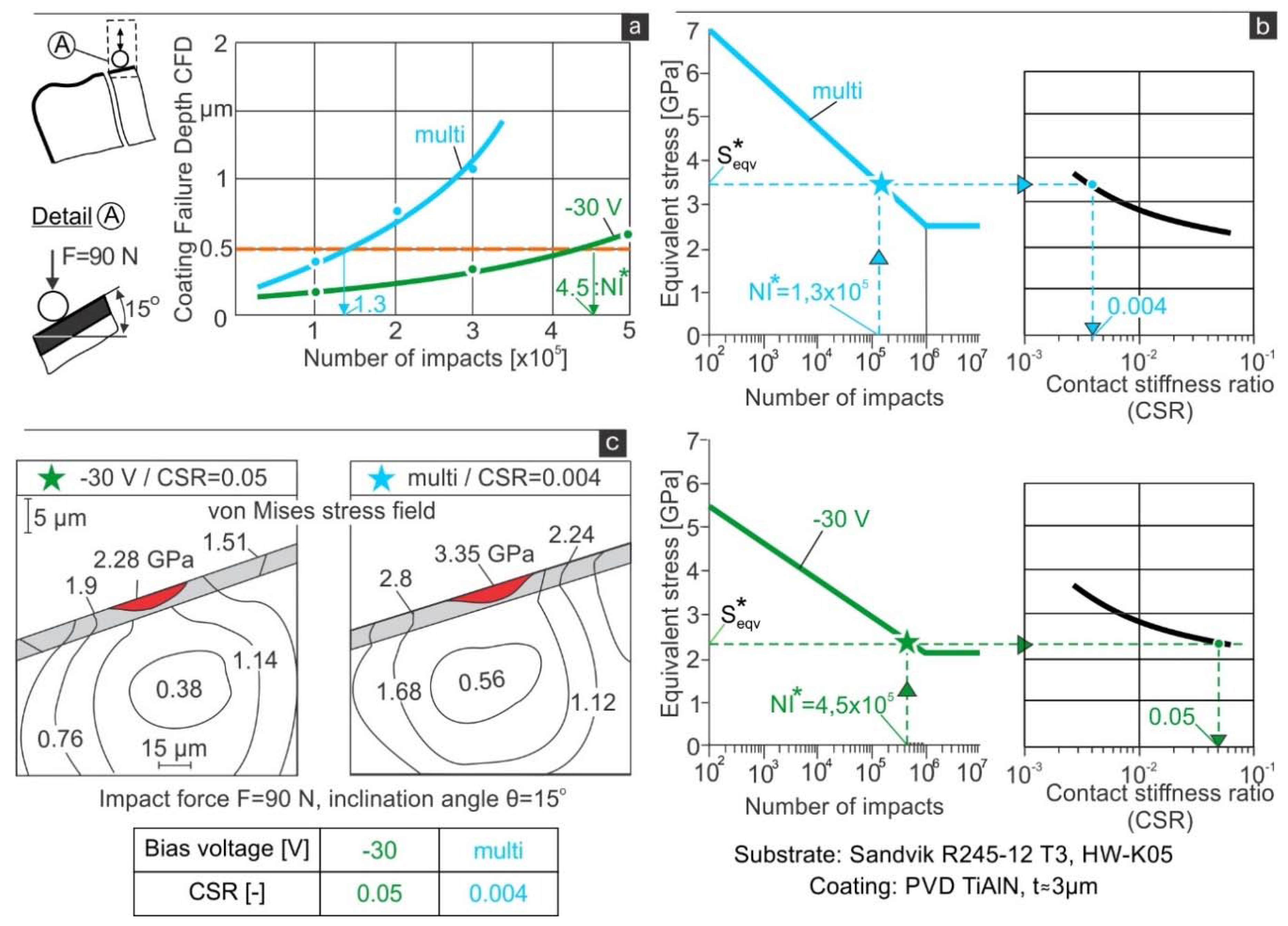
2.3. Association of the CSR with Critical Shear Failure Stress (SFLS)

Based on a method described in [13], the film adhesion can be quantified according to the critical shear failure stress (SFLS). To predict the SFLS in the coating–substrate region, a 3D-FEA model that dynamically simulates the inclined impact test was developed. The occurring SFLS at the coating–substrate interface affects the stresses resulting in the film during the operation of a coated component. In this way, they may lead to potential film material overloading and its cohesive failure. In the right part of Figure 6, the effect of the shear failure stress percentile decrease on the film overloading during the inclined impact test is shown. Moreover, the maximum stress percentile increase at a lower CSR is estimated considering the ideal adhesion (CSR = 1) as a reference. Thus, the maximum stress percentile increase at various CSRs can be related to certain SFLS percentile decreases (see Figure 6). For example, when the CSR amounts to about 0.1 or 0.01, the SFLS percentile decrease amounts to 18 or 50%, respectively, and a maximum film stress percentile increase of 4.5 and 16% develops in the corresponding cases.

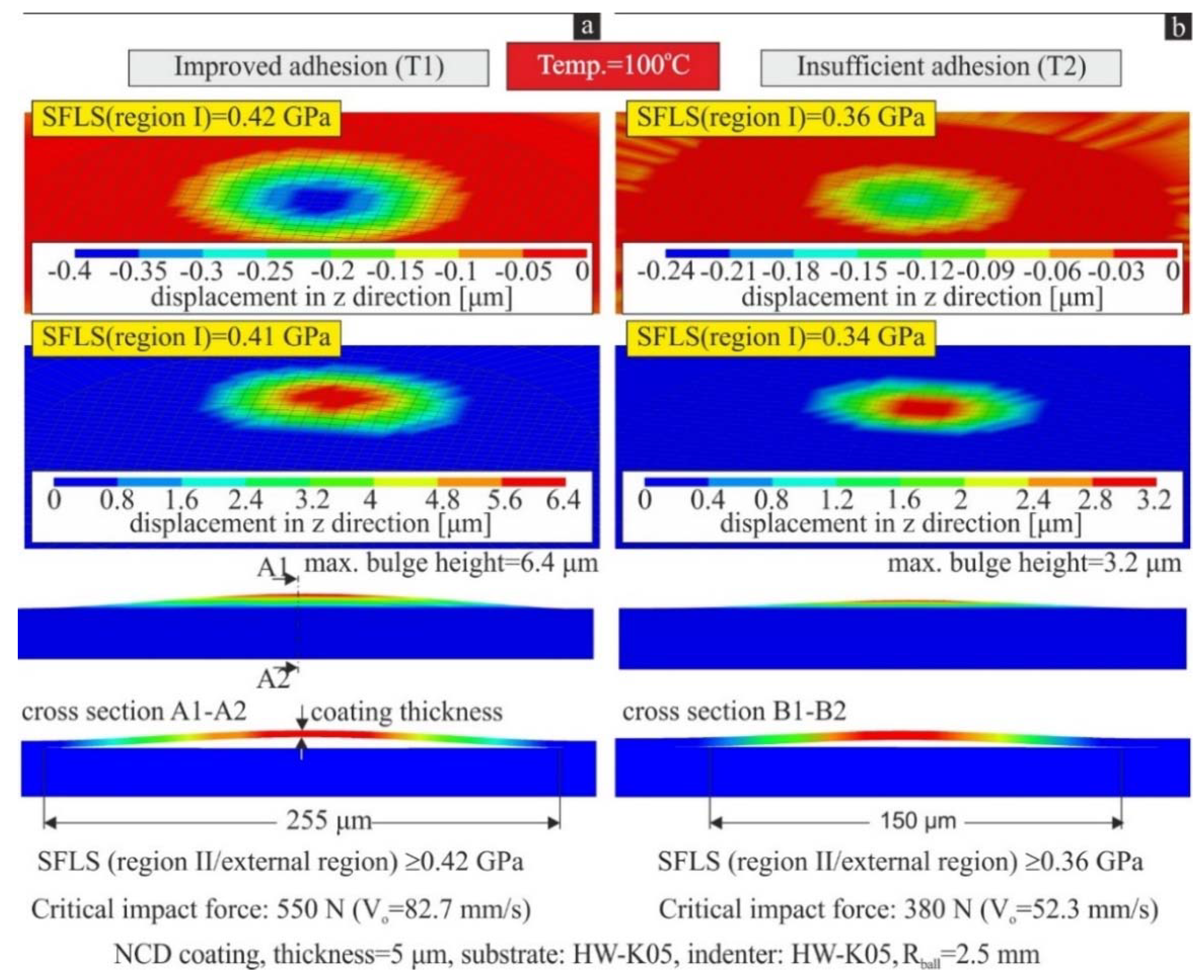
3. Diamond Coating Interfacial Fatigue Strength

Recently, a dynamic 3D-finite element method (FEM) thermo-mechanical model was developed for quantifying the temperature-dependent fatigue strength of a nanocrystalline diamond (NCD) coating–substrate interface [14,15]. This model dynamically simulates the inclined impact test on NCD-coated cemented carbide inserts considering the temperature-dependent residual stresses in the NCD coating’s structure [16,17]. Fatigue damage at the NCD coating–substrate interface develops after a certain number of repetitive impacts depending on the applied impact load and temperature [14]. After the interface fatigue failure, the high compressive residual stresses of the NCD coating structure are released, and the detached coating hikes up at a certain maximum height (bulge formation). The critical impact forces for preventing the fatigue failure of the NCD coating–substrate interface and the subsequent film detachment after 106 impacts at various temperatures were determined by conducting inclined impact tests up to 400 °C. Considering the critical impact forces and by using the mentioned FEA model, the related shear failure stresses in the NCD coating–substrate interface for triggering the coating detachment at various temperatures can be predicted.
By using the previously described FEM model [14,15], the critical SFLS values for preventing the fatigue damage of the NCD coating–substrate interface after 106 impacts at various temperatures were estimated for different adhesion qualities. Figure 7a,b show characteristic calculated imprints at various SFLS values, after the ball indenter removal at a test temperature of 100 °C. There was a remaining displacement of ca. 0.4 μm in the improved NCD film adhesion case, at an SFLS equal to 0.42 GPa, after the ball removal due to substrate plastic deformation (see Figure 7a). A slight decrease in SFLS from 0.42 to 0.41 GPa in Region I resulted in coating detachment and bulge formation. Thus, an SFLS of 0.42 GPa was associated with the maximum operational stress permitted at the NCD coating–substrate interface for preventing the coating detachment initiation at a temperature of 100 °C. Related FEM calculations were carried out in the insufficient NCD film adhesion case at the same temperature of 100 °C. The percentile decrease in the SFLS in the insufficient adhesion case compared to that of the improved one amounted to approximately 17%.
The courses of the FEM-determined critical SFLS values for preventing the initiation of NCD coating detachment versus the temperature after 106 impacts for both adhesion cases are illustrated in Figure 8. The related functions describing the SFLS course versus the temperature are also shown in Figure 8. The predicted SFLSs decrease as the test temperature grows for both investigated adhesion cases. This fact can be attributed to the corresponding reduction of the critical impact load and to the diminished residual stresses at higher temperatures [14]. Moreover, the SFLS decreases more intensely in the case of the insufficient adhesion compared to in the case of the improved one.

4. Conclusions

The impact test has been used for several years, among others, for characterizing coated surfaces’ properties. In the paper, methodologies based on impact tests supported by FEA modeling for predicting the fatigue and adhesion properties of PVD and diamond coatings as well as characteristic application examples were presented. These contribute to the explanation of the operational behavior of the related parts, ascertaining the significance of this test method in the area of surface engineering.

Funding

This research received no external funding.

Conflicts of Interest

The authors declare no conflict of interest.

References

  1. Bobzin, K. High-performance coatings for cutting tools. CIRP J. Manuf. Sci. Technol. 2017, 18, 1–9. [Google Scholar] [CrossRef]
  2. Tönshoff, H.; Blawit, C.; Rie, K.; Gebauer, A. Effects of surface properties on coating adhesion and wear behaviour of PACVD-coated cermets in interrupted cutting. Surf. Coat. Technol. 1997, 97, 224–231. [Google Scholar] [CrossRef]
  3. Yamamoto, K.; Abdoos, M.; Ahmed, Y.S.; Stolf, P.; Beake, B.D.; Rawal, S.; Fox-Rabinovich, G.; Veldhuis, S.C. Cutting Performance of Low Stress Thick TiAlN PVD Coatings during Machining of Compacted Graphite Cast Iron (CGI). Coatings 2018, 8, 38. [Google Scholar] [CrossRef]
  4. Bouzakis, K.-D.; Michailidis, N.; Skordaris, G.; Bouzakis, E.; Biermann, D.; M’Saoubi, R. Cutting with coated tools: Coating technologies, characterization methods and performance optimization. CIRP Ann. 2012, 61, 703–723. [Google Scholar] [CrossRef]
  5. Beake, B.D.; Fox-Rabinovich, G.S.; Veldhuis, S.C.; Goodes, S.R. Coating Optimization for High Speed Machining with Advanced Nanomechanical Test Methods. Surf. Coat. Technol. 2009, 203, 1919–1925. [Google Scholar] [CrossRef]
  6. Constantinides, G.; Tweedie, C.A.; Holbrook, D.M.; Barragan, P.; Smith, J.F.; Van Vliet, K.J. Quantifying deformation and energy dissipation of polymeric surfaces under localized impact. Mater. Sci. Eng. A 2008, 489. [Google Scholar] [CrossRef]
  7. Bouzakis, K.-D.; Vidakis, N.; David, K. The concept of an advanced impact tester supported by evaluation software for the fatigue strength characterization of hard layered media. Thin Solid Film. 1999, 355, 322–329. [Google Scholar] [CrossRef]
  8. Bouzakis, K.-D.; Maliaris, G.; Makrimallakis, S. Strain rate effect on the fatigue failure of thin PVD coatings: An investigation by a novel impact tester with adjustable repetitive force. Int. J. Fatigue 2012, 44, 89–97. [Google Scholar] [CrossRef]
  9. Coatings Testing Experts. Available online: http://www.impact-bz.com (accessed on 30 April 2020).
  10. Bouzakis, K.-D.; Asimakopoulos, A.; Skordaris, G.; Pavlidou, E.; Erkens, G. The inclined impact test: A novel method for the quantification of the adhesion properties of PVD films. Wear 2007, 262, 1471–1478. [Google Scholar] [CrossRef]
  11. Bouzakis, K.-D.; Charalampous, P.; Skordaris, G.; Dimofte, F.; Ene, N.; Ehinger, R.; Gardner, S.; Modrzejewski, B.; Fetty, J. Fatigue and adhesion characterization of DLC coatings on steel substrates by perpendicular and inclined impact tests. Surf. Coat. Technol. 2015, 275, 207–213. [Google Scholar] [CrossRef]
  12. Skordaris, G.; Bouzakis, K.-D.; Charalampous, P.; Kotsanis, T.; Bouzakis, E.; Bejjani, R. Bias voltage effect on the mechanical properties, adhesion and milling performance of PVD films on cemented carbide inserts. Wear 2018, 50–61. [Google Scholar] [CrossRef]
  13. Skordaris, G. Fatigue Strength of Diamond Coating-Substrate Interface Quantified by a Dynamic Simulation of the Inclined Impact Test. J. Mater. Eng. Perform. 2014, 23, 3497–3504. [Google Scholar] [CrossRef]
  14. Skordaris, G. Temperature-Dependent Fatigue Strength of Diamond Coating-Substrate Interface Quantified via the Shear Failure Stress. J. Mater. Eng. Perform. 2015, 24, 3335–3342. [Google Scholar] [CrossRef]
  15. Skordaris, G. Effect of the temperature dependent residual stresses of diamond coated tools with different adhesion qualities on their interfacial fatigue strength. J. Balk. Tribol. Assoc. 2016, 22, 1776–1786. [Google Scholar]
  16. Woehrl, N.; Hirte, T.; Posth, O.; Buck, V. Investigation of the coefficient of thermal expansion in nanocrystalline diamond films. Diam. Relat. Mater. 2009, 18, 224–228. [Google Scholar] [CrossRef]
  17. Lee, D.-G.; Fitz-Gerald, J.M.; Singh, R.K. Novel method for adherent diamond coatings on cemented carbide substrates. Surf. Coat. Technol. 1998, 100, 187–191. [Google Scholar] [CrossRef]
Figure 1. Impact tester and the related fixtures for conducting perpendicular and inclined impact tests.
Materproc 02 00013 g001
Figure 2. Experimental-computational procedures to determine the fatigue strength and the contact stiffness ratio (CSR) between the coating and substrate.
Materproc 02 00013 g002
Figure 3. Wear evolution on a coating during the perpendicular impact test.
Materproc 02 00013 g003
Figure 4. (a) Created Smith-like diagrams for the applied coatings deposited at various bias voltages based on a FEM-supported determination of the developed film stresses during the loading and relaxation stage of the perpendicular impact test. (b) Established Woehler-like diagrams and the defined fatigue endurance stresses of the investigated coatings.
Materproc 02 00013 g004
Figure 5. (a) Coating failure depth versus the number of impacts during the inclined impact tests on the investigated PVD films. (b) Determination of the contact stiffness ratios (CSR), quantifying the adhesion of the tested coatings. (c) FEM-calculated equivalent stress distributions during the inclined impact test on the coatings prepared at −30 V and multi-bias voltage possessing different adhesion strengths.
Materproc 02 00013 g005
Figure 6. Relationship between contact stiffness ratio and shear failure stress percentile decrease.
Materproc 02 00013 g006
Figure 7. Characteristic nanocrystalline diamond (NCD)-coated specimen’s imprints at various critical shear failure stresses (SFLSs), after the ball removal at a test temperature of 100 °C in the case of improved (a) and insufficient (b) adhesion.
Materproc 02 00013 g007
Figure 8. Effect of the operational temperature during the inclined impact test on the critical SFLS for preventing the interfacial fatigue damage of NCD coatings in the investigated adhesion cases.
Materproc 02 00013 g008
Publisher’s Note: MDPI stays neutral with regard to jurisdictional claims in published maps and institutional affiliations.

