1. Introduction
Nowadays, bio-electrochemical systems such as Microbial Fuel Cells (MFCs) and Microbial Electrolysis Cells (MECs) draw increasing attention for their potential applications in sustainable energy production. In both MFCs and MECs systems, the anode electrode plays a crucial role in improving the overall devices’ performances, and numerous studies have been aimed at increasing the electrode’s surface hydrophilicity, porosity and electrical conductivity [
1]. To this end, promising results were obtained by electrode surface optimisation with both Poly(3,4-ethylenedioxythiophene):poly(styrenesulfonate) (PEDOT:PSS) and Polyethylene oxide (PEO) [
1,
2]. Indeed, PEDOT:PSS is a well-known conductive polymer and has already found applications in many sectors, among which are energy conversion and storage. In addition, other works have demonstrated how surface decoration with PEO increased electrodes’ surface hydrophilicity and, in MFCs, promoted the proliferation of the biofilm that is crucial for the proper functioning of such devices [
2]. In this work, we focus on Electrospray and Ultrasonic Spray Coating as two promising and innovative fabrication techniques for the deposition of PEO and PEDOT:PSS solutions on commercial carbon paper. Both techniques are scalable and offer fine control over the deposition of nanostructured layers. While previous works already processed PEDOT:PSS with electrochemical methods [
1], this is the first time that such material has been deposited on MFC electrodes with ES or USC techniques.
Employing both ES and USC, we fabricated samples on which we then characterised the morphology and the electrochemical properties provided by the nanostructured layer. In addition, we investigated the use of Raman spectroscopy to quantitatively validate and map the spatial uniformity of such layers. Finally, we assessed performance improvements and stability in laboratory MFC devices.
2. Materials and Methods
2.1. Materials and Electrodes Fabrication
We fabricated all electrodes, starting from as-purchased commercial Carbon Paper (AvCarb, Lowell, MA, USA). To realise the nanostructured coating, we prepared spraying solutions containing Poly(3,4-ethylenedioxythiophene):poly(styrenesulfonate) (PEDOT:PSS, 1.3 wt.% water dispersion, purchased from Sigma Aldrich), Polyethylene oxide (PEO, 600 kDa average molecular weight, purchased from Sigma Aldrich Darmstadt, Germany), and de-ionised water (Merck Millipore, Darmstadt, Germany).
Electrolyte solutions for electrochemical characterisation contained sodium acetate, ammonium chloride, potassium chloride and sodium dihydrogen phosphate, all purchased from Sigma Aldrich.
2.1.1. Anode Fabrication via Ultrasonic Spray Coating (USC)
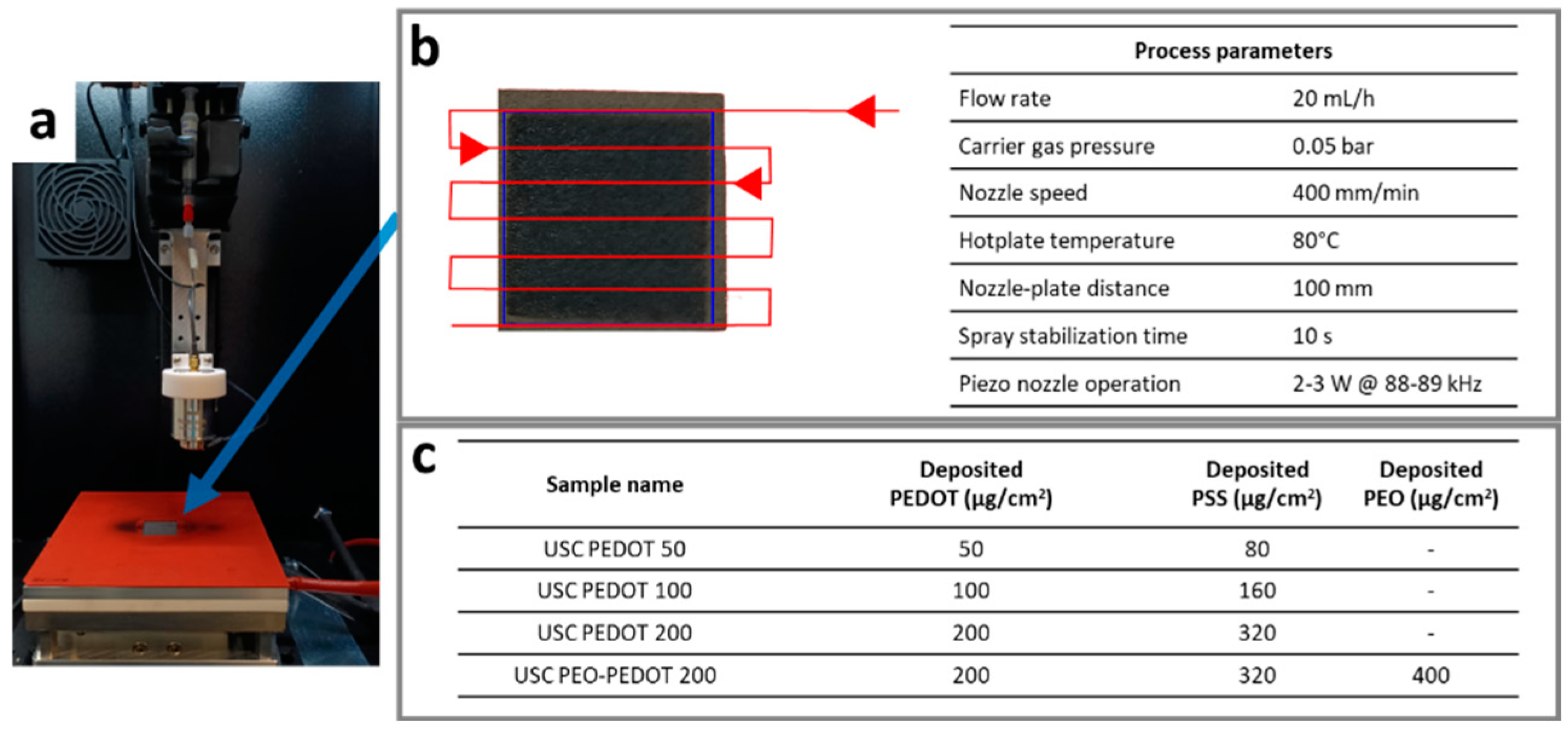
We employed a Nadetech Ultrasonic Spray Coater (Nadetech Innovations, Navarra, Spain) to deposit the PEDOT:PSS nanostructured layer on bare carbon paper. The sprayed solution consisted of a commercial PEDOT:PSS aqueous dispersion (0.5 wt.% PEDOT, 0.8 wt.% PSS), diluted in de-ionised water (2/8 volume ratio). As a result, the final solution contained 1 mg/mL of PEDOT and 1.6 mg/mL of PSS, providing us with a finer control over the deposited material amount with respect to pure commercial solution. Instead, in order to deposit both PEO and PEDOT:PSS, we prepared a spraying solution suitable for USC, starting from the same PEDOT:PSS commercial aqueous dispersion, adding PEO (1 wt.%) and then diluting in deionised water (1/9 volume ratio). Prior to use, we stirred the solution overnight to ensure uniform mixing.
Figure 1a,b describes the process condition and parameters. Fabricated samples, here named
USC PEDOT 50/100/200 or
USC PEO-PEDOT 200, are described in
Figure 1c alongside details on the deposited material amount.
We obtained each electrode sample from a 30 × 30 mm carbon paper square, held in place on the heated deposition plate by vacuum suction and a silicone mask. The deposition duration ranged within 2–6 min, with the spray nozzle following a pattern that aimed at maximising the surface uniformity of deposited material (
Figure 1b).
2.1.2. Anode Fabrication via Electrospray (ES)
We employed a NANON 01A electrospray device (MECC Co. Ltd., Fukuoka, Japan) to deposit PEO and PEDOT:PSS on carbon paper. The spraying solution consisted of pure commercial PEDOT:PSS commercial aqueous dispersion, with the addition of PEO (1 wt.%). Prior to use, we stirred the solution overnight to ensure uniform mixing. As a result, the final solution contained 5 mg/mL of PEDOT, 8 mg/mL of PSS and 10 mg/mL of PEO, and it was properly loaded into a syringe. The ES process was obtained by applying a voltage value of 30 kV, thus guaranteeing the direct deposition of nanodrops onto carbon paper used as a collector substrate. The deposition lasted about 40 min, with a flow rate of 1 mL/h and a nozzle-plate distance of 90 mm. The fabricated electrodes, here called ES PEO-PEDOT 200, contained 200 µg/cm2 of PEDOT, 320 µg/cm2 of PSS and 400 µg/cm2 of PEO. Thus, samples USC PEO-PEDOT 200 and ES PEO-PEDOT 200 allowed us to compare ES and USC as fabrication techniques, being equal the deposited material amount.
2.2. Characterisation Techniques
2.2.1. Morphological and Physical-Chemical Characterisations
To analyse the surface morphology of anode electrodes, we employed a Field Emission Scanning Electron Microscope (FESEM, ZEISS Supra 40, Carl Zeiss AG, Oberkochen, Germany), also featuring a detector for energy-dispersive x-ray (EDX) spectroscopy.
We examined the surface of fabricated anodes using Raman spectroscopy to highlight the presence of PEDOT:PSS by observing its fingerprint peaks. In this work, we also tried to assess how Raman spectroscopy could provide information on the uniformity of the deposited PEDOT:PSS layer. To this end, we analysed our as-fabricated samples, employing a Renishaw inVia™ Qontor Raman Microscope (532 nm laser excitation wavelength). Over the whole samples’ surface, we acquired multiple single-point spectra and a 300 × 250 µm2 map (31 × 17 pixels).
2.2.2. Electrochemical Characterisation and Operation in MFCs
We conducted all electrochemical characterisations using a PalmSens 4 (PalmSens BV, Municipality, The Netherlands) potentiostat. To assess the performance of fabricated electrodes in their intended environment of use, we performed both electrochemical impedance spectroscopy (EIS) and cyclic voltammetry (CV) in an electrolyte solution commonly used in microbial fuel cells. This solution contained sodium acetate (C2H3NaO2, 1 g/L), ammonium chloride (NH4Cl, 0.31 g/L), potassium chloride (KCl, 0.13 g/L) and sodium dihydrogen phosphate (NaH2PO4, 2.450 g/L).
We performed EIS characterisations to investigate the interfaces arising at the anode electrode: the fabricated anodes were analysed in a three-electrode configuration, where they served as working electrodes in contact with the standard MFC electrolyte solution. A platinum wire acted as a counter electrode, while the reference was a Ag/AgCl electrode. For EIS, we applied a 0 V DC bias and an AC sinusoidal signal with a 10 mV amplitude and frequency ranging from 200 mHz to 150 kHz. Employing the same setup, we then conducted CV characterisations, applying potentials from −0.5 V to 0.9 V at 100 mV/s for 5 cycles.
Finally, to study the performances of fabricated electrodes as anodes in MFC devices, we employed a setup and procedures analogous to those described in [
3].
3. Results and Discussion
3.1. Morphological and Physical-Chemical Characterisations
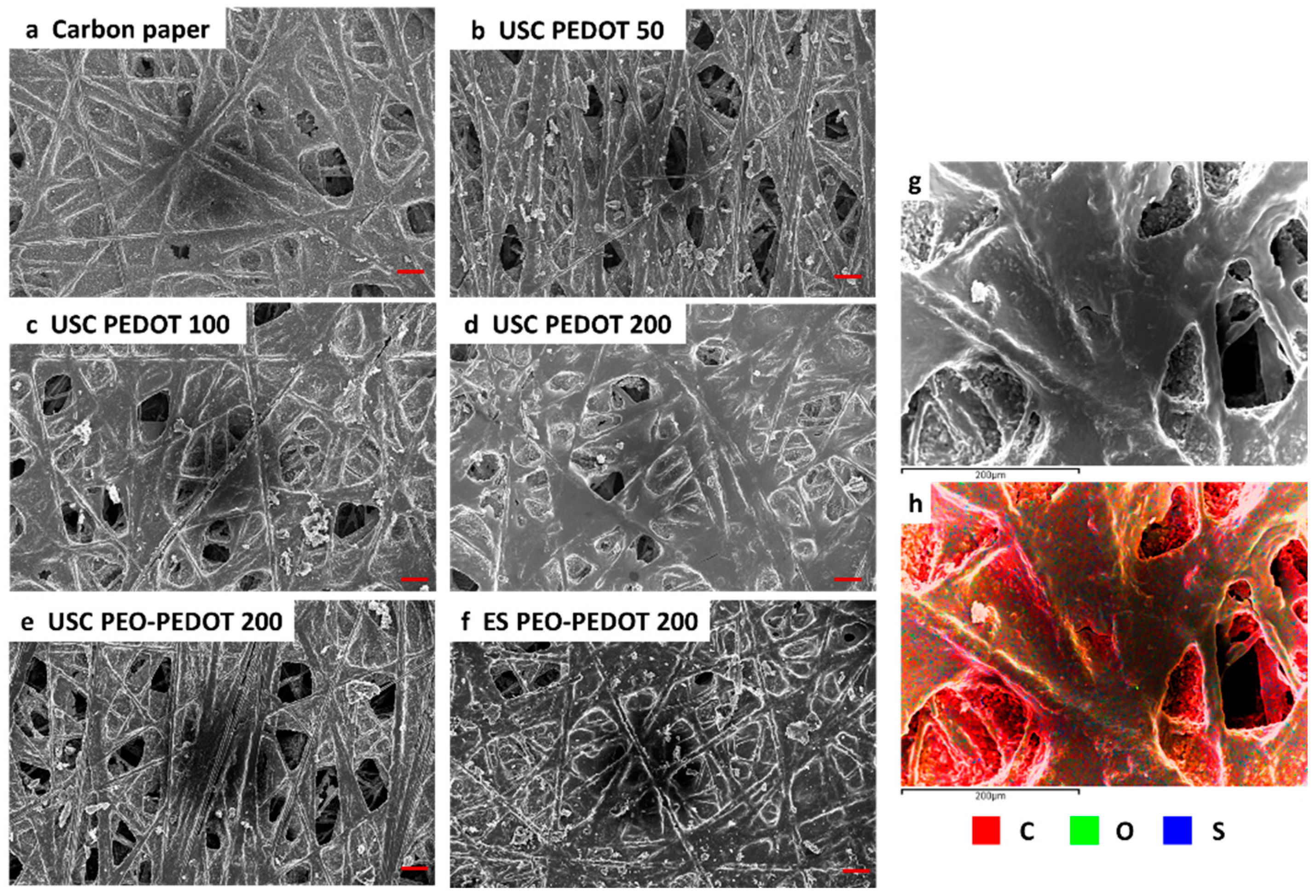
We analysed the morphology of the samples fabricated in comparison with bare commercial carbon paper (
Figure 2a–f). As the amount of the deposited material increased, the PEDOT:PSS layer became more evenly distributed over the surface. Additionally, it was possible to observe a preferential accumulation of deposited material on the most superficial fibres. The samples containing both PEO and PEDOT:PSS confirmed a similar superficial uniformity.
Additionally, the EDX characterisation (
Figure 2g,h) allowed the regions on the samples’ surface where mainly carbon is present (uncovered carbon paper surface) to be distinguished from those also containing oxygen and sulphur (belonging to the deposited PEDOT:PSS).
Raman Characterisation
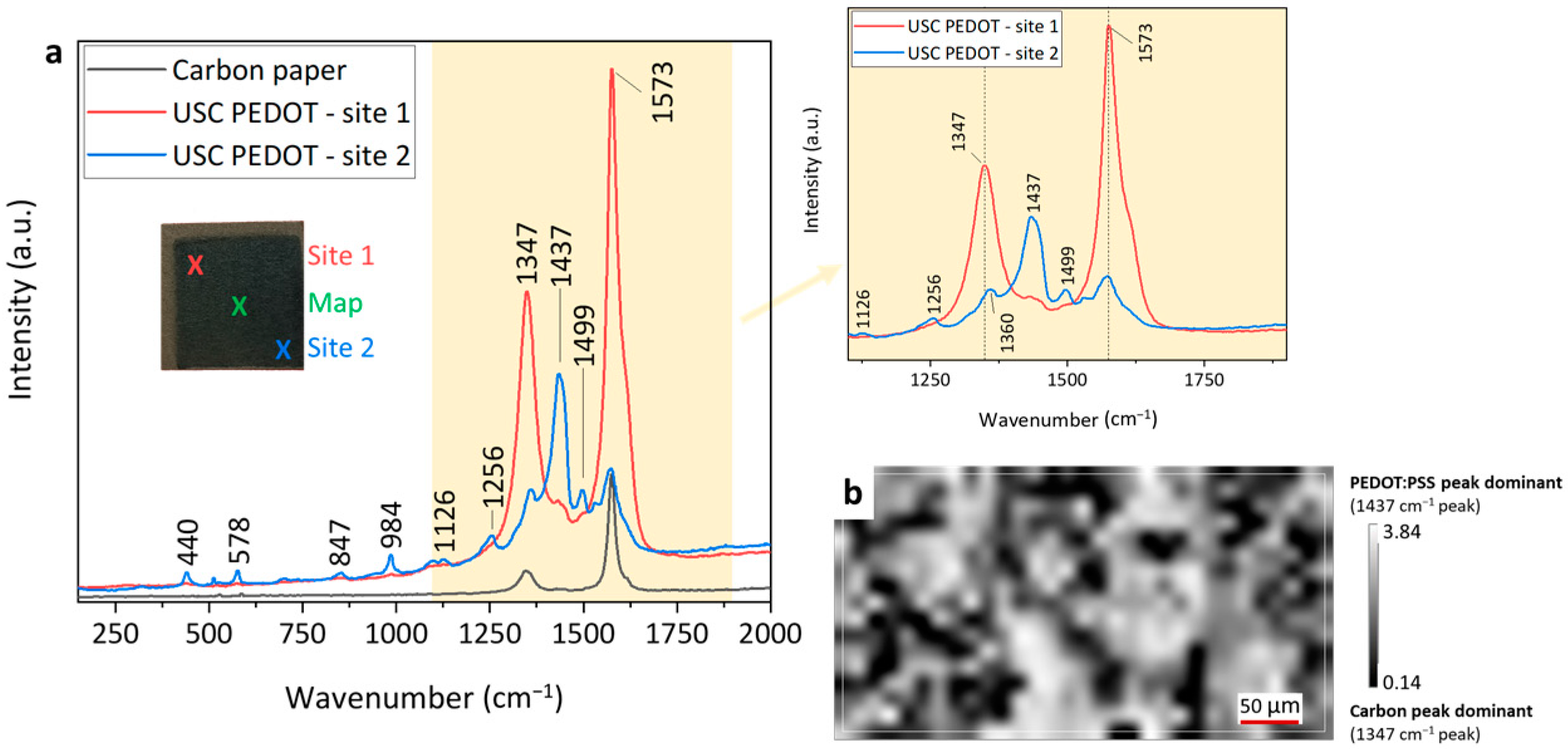
The Raman spectrum of carbon paper (
Figure 3) presented the two peaks typical of carbon-based materials (a D band around 1347 cm
−1 related to the presence of defects, vacancies and bent sp
2 bonds in the graphitic structure, and a G band around 1573 cm
−1, which was related to the in-plane vibration of sp
2 hybridised C-C bonds). When analysing fabricated anodes, the main peaks located at 1256, 1360, and 1437 cm
−1 can be associated with the presence of PEDOT:PSS on top of the carbon paper substrate (respectively, with Cα–Cα′ inter-ring stretching, Cβ–Cβ′ stretching and Cα=Cβ symmetric stretching vibrations [
4,
5]). The other, weaker intensity peaks observed were also in good agreement with those described in detail by Kong et al. [
4].
As shown in
Figure 3a, the two selected Raman spectra acquired at different sites on the sample featured different intensities of characteristic peaks, which hinted at a carbon-dominated (
Site 1) or PEDOT:PSS-dominated (
Site 2) response. Such macroscopic non-uniformity led us to further investigate potential inhomogeneities observable at the micro-scale. To this end, as previously described, we acquired a matrix of single-point measurements, producing a 300 × 250 µm
2 map. Then, by computing the ratio between the intensity of a PEDOT:PSS characteristic peak (1437 cm
−1) with respect to that of a carbon characteristic peak (1347 cm
−1), we obtained a false-colour image representing the relative abundance of PEDOT:PSS (
Figure 3b).
However, this technique could only provide relative abundance information, and was not sufficient to quantify the deposited material amount. Nonetheless, we believe that the Raman mapping technique deserves further investigation, as it might prove useful for comparing deposition uniformity, both at the mm- and µ-meter scale, across several repeated samples, or to compare different deposition techniques.
3.2. Electrochemical Characterisation and Operation in MFCs
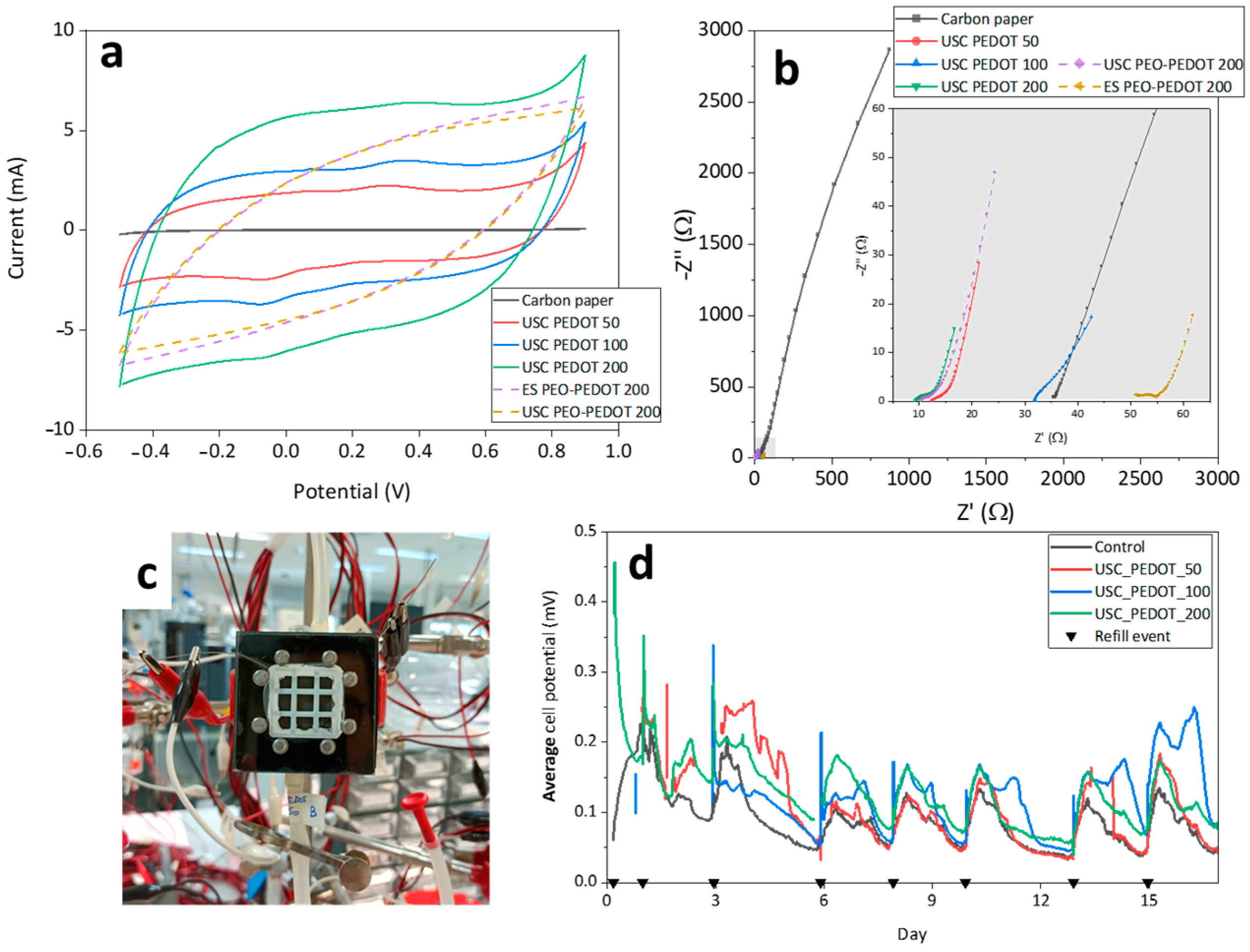
The cyclic voltammetry characterisations demonstrated an electric double-layer capacitance (EDLC) behaviour for all samples (
Figure 4a).
In particular, electrodes fabricated via USC exhibited a direct correlation between the deposited PEDOT:PSS amount and the capacitive response. Compared to bare carbon paper, PEDOT:PSS-modified electrodes featured an increased electrical conductivity thanks to the presence of intrinsically conductive PEDOT. Additionally, the enhanced electric double-layer capacitance could be attributed to the hydrophilic PSS, which increased the surface’s wettability and thus the electrically active area. Noticeably, samples containing both PEO and PEDOT:PSS presented a further deviation from the rectangular response of the EDLC. This could be attributed to an increase in interface resistance induced by the presence of PEO, as well as to the high scan rate employed [
5].
Cyclic voltammograms were reproducible between scans, symmetric between forward and reverse scan, and presented no Faradic response. Such characteristics indicate that so-fabricated electrodes are inactive in electrolytes in microbial fuel cell electrolyte and represent good candidates to be employed in MFC.
The EIS characteristics (
Figure 4b), which could be physically modelled with a Randles circuit, featured a distorted arc at high frequencies, while mass transfer impedances dominated at lower frequencies. The arc distortion was associated with the non-ideal capacitance characteristic of the complex electrode–electrolyte interface. For the
USC PEDOT samples, these results confirmed both the direct correlation between EDLC and the deposited material amount, and that PEDOT:PSS deposition effectively reduced electrodes’ impedances.
Finally, starting from these promising electrochemical results, we assessed the performances of fabricated electrodes as anodes in microbial fuel cell devices, as described in [
3] (and represented in
Figure 4c), assembling a triplet of devices for each deposition previously described.
Figure 4d displays the output potential measured from MFCs, containing
USC PEDOT anode electrodes, during the first 16 days of activity. Each curve represents the average potential of each triplet of MFCs, highlighting how devices containing PEDOT:PSS nanostructured anodes systematically provided a higher potential output compared to bare carbon paper electrodes.
4. Conclusions
In this work, we investigated the use of Electrospray (ES) and Ultrasonic Spray Coating (USC) as innovative fabrication techniques to obtain nanostructured layers for optimising carbon electrodes’ surface. Starting with commercially available polymers, PEO and PEDOT:PSS, we obtained solutions that can be conveniently employed to deposit a nanostructured conductive layer on carbon paper using ES and USC techniques. Both techniques allowed us to finely control the deposited material amount, while requiring processing times ranging from less than one hour down to a few minutes. To the best of our knowledge, this is the first time that such techniques have been employed to deposit PEDOT:PSS on anodes for bio-electrochemical systems.
Employing electron microscopy, we analysed the morphology and uniformity of the nanostructured layer as a function of the material amount deposited with both ES and USC techniques. In addition, we investigated the potential of Raman spectroscopy as a tool to validate and map the relative spatial uniformity of PEDOT:PSS depositions, across both multiple samples and different fabrication techniques.
The electrochemical characterisations demonstrated the improvements given by electrode surface modification previously described, both in terms of reduced electrical impedances and of increased capacitive properties with respect to bare carbon paper.
Finally, experiments performed in MFC devices highlighted, since the early operative stages, the performance improvements provided by ES and USC optimised anodes.
Author Contributions
Conceptualisation, all authors; methodology, G.S., G.M. and M.Q.; validation, G.M. and M.Q.; formal analysis, G.S.; investigation, G.S.; resources, C.F.P. and M.Q.; data curation, G.S., G.M. and S.B.; writing—original draft preparation, G.S.; writing—review and editing, all authors; supervision, G.M., S.B. and M.Q.; project administration, C.F.P., S.B. and M.Q.; funding acquisition, C.F.P., S.B. and M.Q. All authors have read and agreed to the published version of the manuscript.
Funding
This research received no external funding.
Institutional Review Board Statement
Not applicable.
Informed Consent Statement
Not applicable.
Data Availability Statement
Data sharing is not applicable to this article.
Conflicts of Interest
The authors declare no conflict of interest.
References
- Cai, T.; Meng, L.; Chen, G.; Xi, Y.; Jiang, N.; Song, J.; Zheng, S.; Liu, Y.; Zhen, G.; Huang, M. Application of Advanced Anodes in Microbial Fuel Cells for Power Generation: A Review. Chemosphere 2020, 248, 125985. [Google Scholar] [CrossRef] [PubMed]
- Massaglia, G.; Frascella, F.; Chiadò, A.; Sacco, A.; Marasso, S.L.; Cocuzza, M.; Pirri, C.F.; Quaglio, M. Electrospun Nanofibers: From Food to Energy by Engineered Electrodes in Microbial Fuel Cells. Nanomaterials 2020, 10, 523. [Google Scholar] [CrossRef] [PubMed]
- Massaglia, G.; Margaria, V.; Fiorentin, M.R.; Pasha, K.; Sacco, A.; Castellino, M.; Chiodoni, A.; Bianco, S.; Pirri, F.C.; Quaglio, M. Nonwoven Mats of N-Doped Carbon Nanofibers as High-Performing Anodes in Microbial Fuel Cells. Mater. Today Energy 2020, 16, 100385. [Google Scholar] [CrossRef]
- Kong, M.; Garriga, M.; Reparaz, J.S.; Alonso, M.I. Advanced Optical Characterization of PEDOT:PSS by Combining Spectroscopic Ellipsometry and Raman Scattering. ACS Omega 2022, 7, 39429–39436. [Google Scholar] [CrossRef] [PubMed]
- Park, S.-G.; Rhee, C.; Jadhav, D.A.; Eisa, T.; Al-Mayyahi, R.B.; Shin, S.G.; Abdelkareem, M.A.; Chae, K.-J. Tailoring a Highly Conductive and Super-Hydrophilic Electrode for Biocatalytic Performance of Microbial Electrolysis Cells. Sci. Total Environ. 2023, 856, 159105. [Google Scholar] [CrossRef] [PubMed]
| Disclaimer/Publisher’s Note: The statements, opinions and data contained in all publications are solely those of the individual author(s) and contributor(s) and not of MDPI and/or the editor(s). MDPI and/or the editor(s) disclaim responsibility for any injury to people or property resulting from any ideas, methods, instructions or products referred to in the content. |
© 2023 by the authors. Licensee MDPI, Basel, Switzerland. This article is an open access article distributed under the terms and conditions of the Creative Commons Attribution (CC BY) license (https://creativecommons.org/licenses/by/4.0/).


 ,
, 


