1. Introduction
A person’s eyes are an important organ, as they process visual information and transmit it to the brain; also, because people receive and process 83% of information from their environment through their eyes, eyes play a crucial role in the lives of humans. Many people are deprived of this information, however. There are a number of severe disabilities, such as blindness, in which a person must face many challenges despite technological advancements. Blindness refers to a condition in people lacking the ability to perceive light, as well as those who have so little vision that they must use other senses as substitutes for their ability to see. The visually impaired refers to a person with complete or partial blindness. According to an 11 October 2017 file from the World Health Organization (WHO), an estimated 253 million human beings are dwelling with imaginative and prescient impairment, out of which 36 million are definitely visually impaired and 217 million have reasonable to extreme imaginative and prescient impairment.
2. Motivation
The proposal to do the job comes from friends and the community. In our society, a large number of blind people struggle to perform their daily activities. These people need the help of others, especially in situations such as crossing roads, seeing obstacles, etc. These events have prompted us to draw up an instrument that will be of great benefit to the blind.
3. Problem Statement
In order to furnish a useful, environmentally friendly navigation resource for blind people, more than a few researchers have conducted the extensive variety of lookup works [
1]. Initially, these humans depended solely on others for their simple wants and mobility. Blind humans have used the white cane and skilled puppies for help [
2], however these techniques have sure limitations. While white canes are inexpensive, they cannot discover boundaries accurately. The user might also solely be in a position to observe limitations via touch, which leaves them with little time to react to adverse conditions. These options are no longer so efficient, as a skilled canine is expensive, and it may get injured or sick [
3]. Thus, these options are no longer efficient. Subsections are introduced and mentioned beneath that describe and analyze the preceding work, primarily based on facets and applied sciences concerned with solely obstacle-detecting digital journey aids (ETAs), or solely impediment detectors alongside function locators and conversation techniques [
4]. There are about 37 million blind humans in the world, with more than 15 million blind human beings residing in India. While congestion of barriers can be troublesome for non-visually impaired human beings as well, it is even more challenging for the visually impaired [
5,
6]. The wants of human beings with visible disabilities are regularly met through exterior assistance. Visually impaired humans may additionally find it hard to navigate via a room or a hallway, barring bumping into objects [
7,
8]. It can be challenging to avoid obstacles, even with an on-foot stick, due to the fact it can be uncomfortable, inconvenient, and inaccurate. In order to allow blind humans to move freely, a mechanism must be developed to help them with their daily activities.
4. Objective
The aim of this mission is to assist blind human beings with walking with ease, and be warned when their walking course is blocked by means of different objects, people, or different comparable obstacles. A buzzer is relayed in the circuit as a warning signal, whose frequency modifications rely on the distance from the object. The nearer the object is, the louder the buzzer beep frequency will be.
5. Proposed System
This device consists of a bodily sensor related to a microcontroller. The code has been written with an Arduino sketch, and the microcontroller is interfaced with the ultrasonic sensor. This Arduino board makes use of the ATmega328p (datasheet) microcontroller. In addition to 14 digital outputs and inputs, 6 of which are PMW outputs, it has 6 analog inputs, a 16 MHz quartz crystal, a USB connection, a strength jack, and an ICSP reset button. When contact is made, two wire probes feel the presence of water by means of the precise resistance of water. Blind customers will be in a position to navigate freely to their favored region with the system. Moreover, it is effortless to use and user-friendly. It is realistic, and is mass made to be used by the visually impaired. The machine has the function of detecting the rear limits located during the movement in and out of navigation. A smart stick is usually an embedded device that combines the following: the effort of the sensory nerves to detect the boundaries ahead of time, rather than the blind from top to top within a distance of 400 cm per head. Inaudible sensors and water sensors capture real-time statistics and send them to a small controller. As soon as this information is available, the microcontroller launches the buzzer. The water gadget sees water below, and the battery is powered by circuits. Hence this proposed system is helpful for visually impaired people with the help of varied component to detect obstacles.
6. Hardware Components
The project includes a simple electronic system that includes the following components: Walking Stick, Arduino (UNO R3), Ultrasonic Sensor (HC-SR04), IR Sensor (A215/450), Water Sensor (LE 25.00), Switch, Voltage regulator, Power supply, Buzzer.
6.1. Components Description
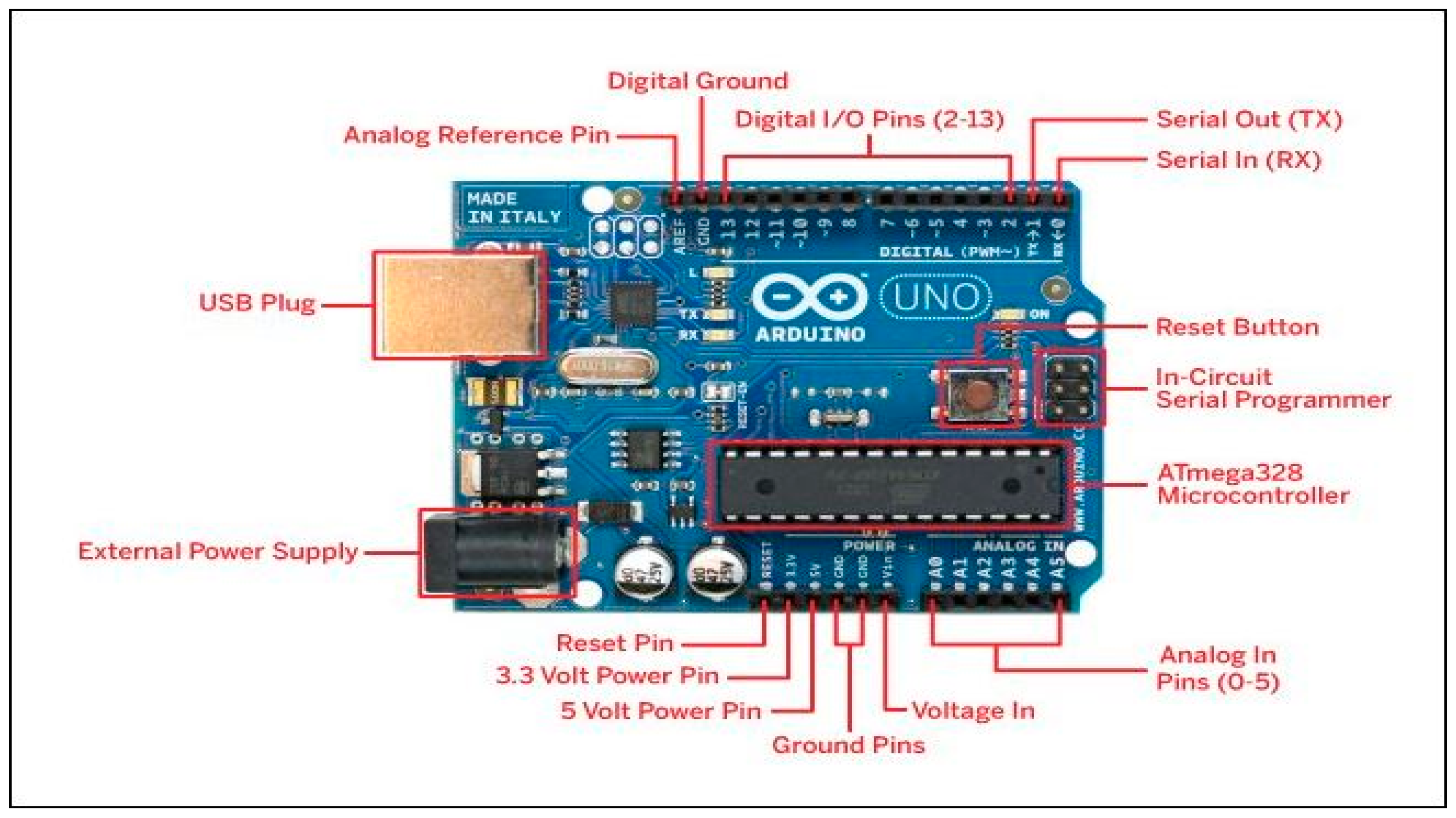
6.1.1. Arduino
Arduino (UNO R3) is an open-source hardware and software company, project and consumer community that designs and builds single-board microcontrollers and microcontroller kits to create digital units and interactive sensors, and controls each body digitally. It can be set up to configure any device with additional sensors. The key features of this board usually include, DIP (Dual-inline-package), removable and AT-mega328 microcontroller. The layout of this board shown in
Figure 1, can be easily downloaded using the Arduino laptop system. This board has great support from the Arduino community, which will make it a much easier way to start working on embedded electronics, as well as in many larger applications.
6.1.2. ULTRASONIC SENSOR (HC-SR04)
The ultrasonic sensor is mainly used for proximity sensor purposes, and in our project this sensor is mainly used as an object detection system. As this application mainly covers blind people, this kind of sensor integrated system is mainly helpful for those kind of people. The sensor which we used in this project covers a distance of about 2 cm to 400 cm, but the main criteria that has to be kept in hand is the environment, which should be free from water vapour because water vapour will spoil the range of the sensor. The distance between the sensor and the object will be sensed and the information will be given to the microcontroller so that the alarm will be turned on and it will be elucidated to the subject. This ultrasonic sensor module is a four-pin module whose pins are Vcc, Trigger, Echo and Ground, respectively.
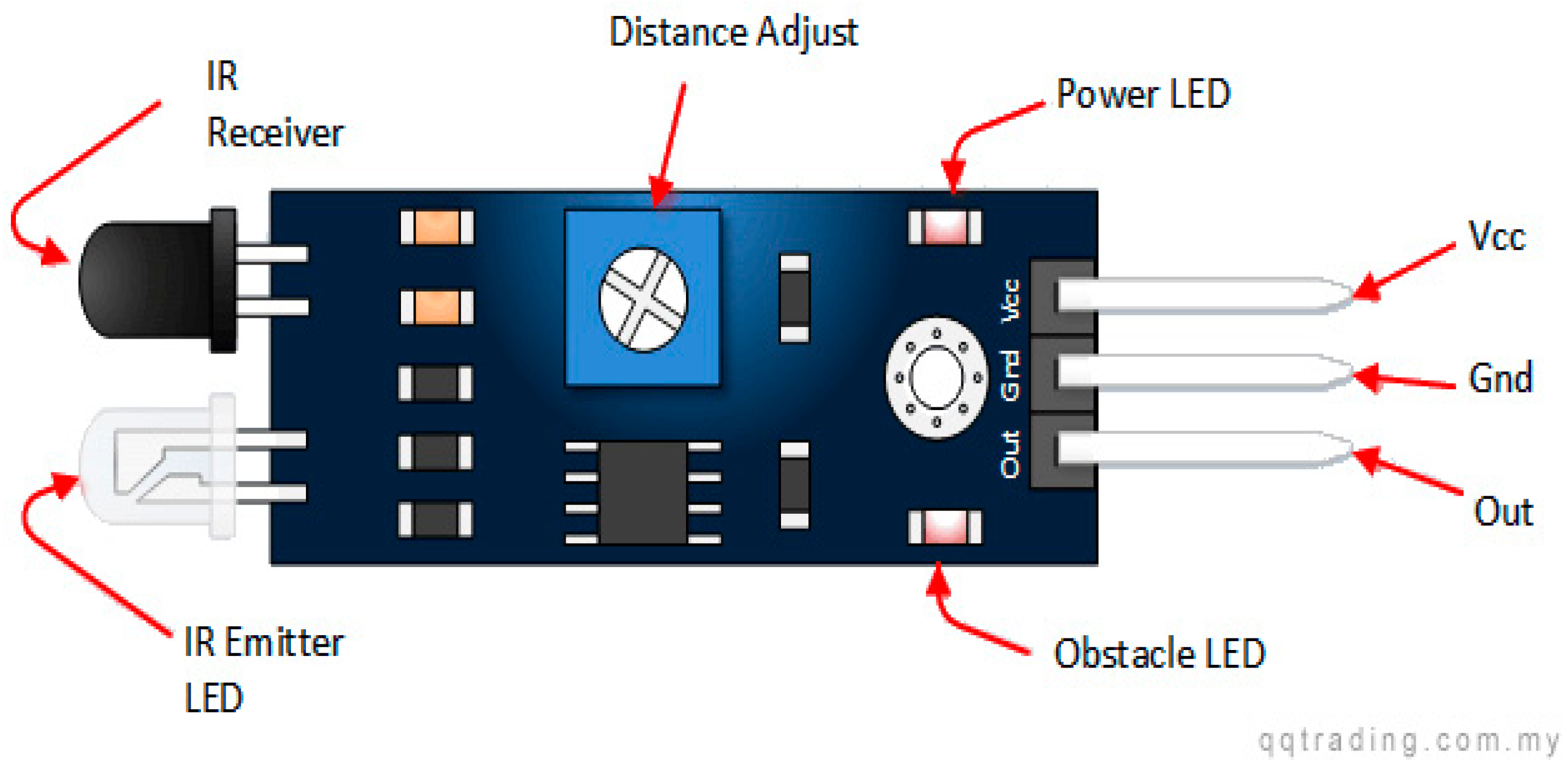
6.1.3. IR SENSOR (A215/450)
The IR sensor module consists mainly of an IR Transmitter and Receiver, OPamp, Variable Resistor (Trimmer pot), and LED outlet. IR LED Transmitter: IR LED emits light, in a wide infrared frequency. IR light is not visible to humans as its wavelength (700 nm–1 mm) is much higher than the visible light intensity. IR LEDs have an optical illuminating angle of approximately 20–60 degrees, and range of approximately a few inches to several feet, depending on the type of IR transmitter and the manufacturer. Some transmitters operate with a range of several miles. An IR LED is white or transparent in color, so it can provide high light intensity. Photodiode Receiver: the photodiode acts as an IR receiver as it operates when light falls on it. A photodiode is a semiconductor with a P-N junction, which operates in Reverse Bias, which means it initiates current in reverse direction when light drops in it, and the current flow value is equal to the amount of Light. This feature makes it useful for IR detection. A photodiode looks like an LED, with a black color on its outer surface; the black color absorbs a very high amount of light shown in
Figure 2.
6.1.4. LM358 Op-Amp
The LM358 is an Operational Amplifier (Op-Amp) used as a voltage comparator for IR sensors. The comparator will compare the threshold voltage set using pre-set (pin2) and photodiode’s resistor voltage (pin3). The photodiode’s series resistor voltage drop > Threshold voltage = Opamp output is high, and photodiode’s series resistor voltage drop < Threshold voltage = Opamp output is low. When the Opamp output is high, the LED at the Opamp output terminal turns ON (Indicating Detection of object).
6.1.5. WATER SENSOR (LE 25.00)
The water sensor brick is designed for water detection, which can be widely used to detect rainfall, water level, and even leak liquate. The brick is mainly made up of three parts: an electronic brick connector, 1 MΩ resistor, and several rows of bare wires. This sensor works by having a series of exposed trackers connected to the ground, and connected between ground-based tracking sensors. Sensor traces have a weak pull-up resistance of 1 MΩ. The resistor will pull the value of the sensor trace up until the drop of water sensor traces to the bottom track. Believe it or not, this circuit will work with your Arduino digital I/O pins, or you can use it with analog pins to detect the amount of water-generated connections between the ground track and the sensors. This item can judge the water level through a series of interlocking strings to measure a drop of water/size. This sensitive water sensor can easily convert the water amount to an analog signal, and the output analog value can be applied directly to the system function, and then to accomplish the function of a water level alarm. This item has low power consumption, and high sensitivity, which are major features of this module. The High Sensitivity Water Sensor can be compatible with Arduino UNO, Arduino mega2560, Arduino ADK, etc.
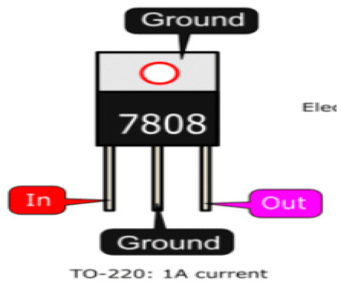
6.1.6. VOLTAGE REGULATOR (LM 7808)
The LM7808 series of three terminal positive controls are available in the TO-220 package, with several constant output voltages, making them useful for many different applications. Each type uses an internal current limit, thermal shut-off and protection of a safe working environment, which prevents it from failing. If a sufficient immersion temperature is provided, it can produce an output of more than 1A current. Although it was designed primarily as a fixed power controller, these devices can be used with external components to obtain adjustable voltages and currents shown in
Figure 3. One of the main advantages of these voltage regulators is that no matter if the input voltage fluctuates, they will provide a fixed voltage at the output, but the input voltage should not be less than the minimum required voltage of the ICs. The input voltage in any condition must be 2 V to 3 V higher than the output voltage. To get a stable 8 V output from LM7808 as discussed above, it is suggested that the input voltage must be at least 2 to 3 V higher than the output voltage. The IC is a DC device, so the input voltage must be DC. Additionally, to get 1.5 A at the output the input current should be at least 2 A.
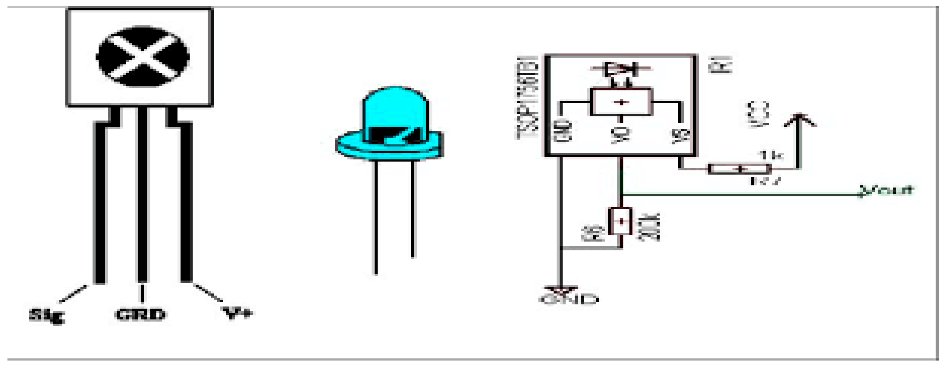
6.1.7. PHOTO DIODE RECEIVER
The photo diode acts as an IR receiver as it operates when light falls on it. The photo diode is a semiconductor with a P-N junction, which operates in the reverse bias, which means it begins to conduct the current in a backward direction when the light drops on it, and the current flow value is equal to the amount of light. This feature makes it useful for IR detection. The photodiode looks like an LED, with black on the outside which is shown in
Figure 4. The black color absorbs the maximum amount of light.
6.1.8. BUZZER
The buzzer is a small but effective component for adding audio features to our project/system. It is very small and compact with 2 pins, which is why it can be easily used on bread board, Perf Board and even PCBs, making this a widely used component in many electrical systems. There are two types of buzzers commonly found. The one shown here is a simple buzzer, that if enabled will make a continuous beep sound; another type called a ready-made buzzer that will look bigger and will produce a “Beep. Beep. Beep.” sound due, to the internal oscillating circuit located inside it. But the one shown here is the most widely used because it can be customized with the help of other regions to easily fit into our app. This buzzer can be operated by simply powering it using a DC power supply ranging from 4 V to 9 V. A simple 9 V battery can also be used, but it is recommended that you use a +5 V or +6 V DC controlled supply. The buzzer is usually associated with a switch on the “ON” or “OFF” of the bus when needed and requires an interval shown in
Figure 5.
7. Discussion
For further enhancement, our project will be integrated with more powerful sensors which will provide precise information about the detection of obstacles in a wide range. A suitable mobile application will also be developed along with the product design, which can help to identify the location of user, and guide the user the right way by giving voice guidance through headphones connected with the product. Our product will make use of GPS to find the shortest and best path to the destination with the help of Google mapping systems. We will attach GSM in our product, which can help in future for any immediate casualty help. We will make our product more compact by using VLSI technology to design PCB unit.
8. Conclusions
It is worth mentioning at this point that the purpose of this study, which is to design and use a clever and smart walking stick for visually impaired people, is fully realized. The Smart Stick serves as a basic platform for the next generation of assistive devices to help the visually impaired to navigate safely inside and out. It is practical and affordable. It leads to good results in finding obstacles in the user’s path over a distance of 3 m. This system provides a low cost, reliable, portable, low power consumption and a robust navigation solution with short clear response time. Although the system has strong nerves and other components, it has a light weight. Other features of this system can be enhanced by connecting wireless components between the components, thus increasing the range of the ultrasonic sensor and the use of the speed detection technology. While developing such an enabling solution, visually impaired and blind people in all developing countries were at the top of our priorities. The device built into this function can only detect obstacles and moisture. Holes cannot be detected using this device or other types of obstacle. Therefore, a better device can be built using ultrasonic sensors; Arduino Uno and other tools that use audio commands to alert the user of what is in his or her way. The vibrator can also be added to make it easier to use. In the future, some changes to improve system performance will be added. These include: Global Positioning System for GPS User Location, and GSM modules to communicate the location with a relative or caregiver. It should also include a wide variety of handles for flexible management.


