Proceeding Paper

Unsymmetrical Fault Analysis and Protection of 1.5 MW DFIG Wind Turbine Converters †

Department Electrical Power Engineering, U.S. Pakistan Center for Advanced Studies in Energy (USPCAS-E), National University of Science and Technology, Sector H-12, Islamabad 44000, Pakistan
*
Author to whom correspondence should be addressed.
Presented at the 7th International Electrical Engineering Conference, Karachi, Pakistan, 25–26 March 2022.
Eng. Proc. 2022, 20(1), 41; https://doi.org/10.3390/engproc2022020041
Published: 9 August 2022
(This article belongs to the Proceedings of The 7th International Electrical Engineering Conference)

Abstract

:
Due to rapid increase in the installation of renewable energy resources in the grid, the use of power electronic-based devices is increasing day by day. Whenever a wind farm is installed and integrated with the grid, most of the work and control depends on its electronic converters. Whenever a grid fault occurs, it can cause significant overcurrents and overvoltage, placing the entire facility at risk. It can quickly cause the converter system to deteriorate if countermeasures are not taken. Thus, a proper protection scheme is needed to protect the generator and its converter from faults. In this paper, an asymmetrical fault analysis and protection scheme is presented in which a single line to ground fault is created, followed by a check of its effects on the DFIG, rotor circuit and converters. Then, a proper protection scheme for a crowbar circuit is designed and we assess its operation on a 1.5 MW DFIG-based industrial wind turbine model in EMTDC/PSCAD.

1. Introduction

There has been a significant increase in the energy demand and environmental issues. The world is thus shifting towards renewable energy resources and its technologies, because these resources are clean and their operation is free of cost. Wind is one of the renewable energy resources. It should be of no surprise that electricity in the future will be produced largely through the installation of wind farms [1]. However, there are certain challenges associated with the use of wind energy, such as the impacts of wind turbine generators on the integration with the power systems, and also the variation in the wind speed. The concept of a variable-speed wind turbine (VSWT) with a doubly-fed induction generator (DFIG) is gaining popularity due to its distinct advantages over fixed-speed induction generators, such as increased power capture and a four-quadrant converter topology that allows decoupled and fast active and reactive power control, and lower mechanical stresses [2]. Due to the variable wind speed, wind turbines with DFIG doubly fed induction generators are extensively used, as they can be easily controlled under varying wind speeds and can maintain the connection with the public grid and the stability of the power output [3].
Although DFIG-based wind turbines have been successful, there are still several challenges that need to be solved. In a highly competitive power system, voltage imbalance with magnitudes that differ from one another is quite common, owing to faults [4]. In normal conditions, the rotor converter adjusts the rotor current during normal operation to obtain the active and reactive reference powers [5]. The single and three-phase line faults represent special cases of high currents and voltage dips. The voltage completely drops during faults [6,7,8]. High currents are induced in the machine during line faults, causing the system to become imbalanced [9]. Transmission line faults provide a large flow of current to the rotor side of the DFIG, which is connected by back-to-back converters; the converters may be damaged due to these high currents. Thus, a proper protection scheme is needed to protect the DFIG and converter from the transients and faults [10].
This paper will examine the behavior and analysis of the asymmetrical single line to ground fault on a 22 kV HT line connected to a wind turbine. Whenever these faults occur, they can cause significant overcurrents and overvoltages, placing the entire facility at risk. This quickly causes the converter system to deteriorate if countermeasures are not taken. Thus, a proper protection scheme is needed to protect the generator and its converter from faults.

2. Analysis of DFIG in Normal Operation

The study has been conducted on a 1.5 MW industrial wind turbine model, as shown in Figure 1, in which the DFIG with a rating of 1.73 MVA is connected to back-to-back converters of rating 770 kVA. When the DFIG is operating in normal conditions, its nominal output voltage is 690 Volts. To raise its voltage, it is connected to a step-up transformer, which increases its voltage up to 22 kV. The other side is fed by a three-phase nominal voltage of 132 kV, which is reduced by a step-down transformer to 22 kV. The simulation results are shown in the following sections.

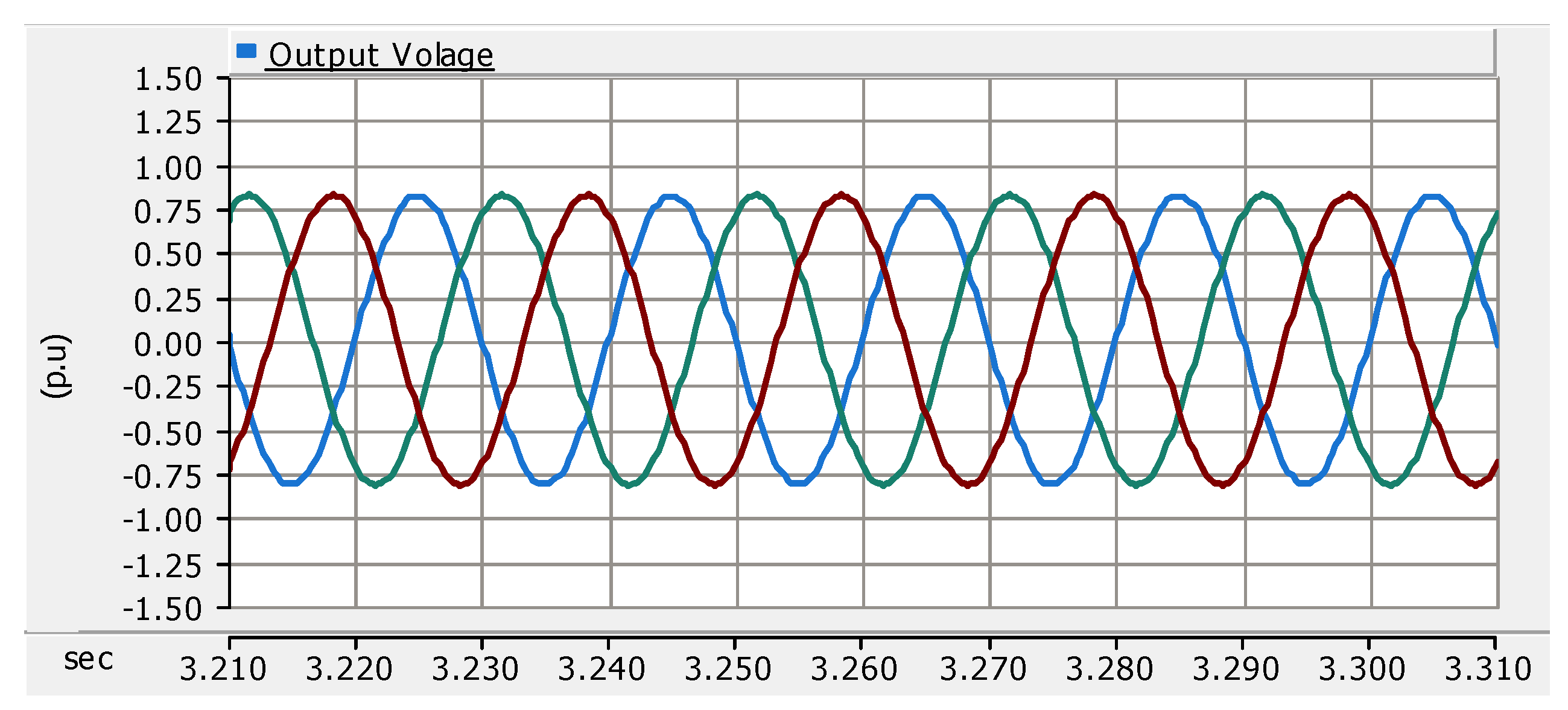
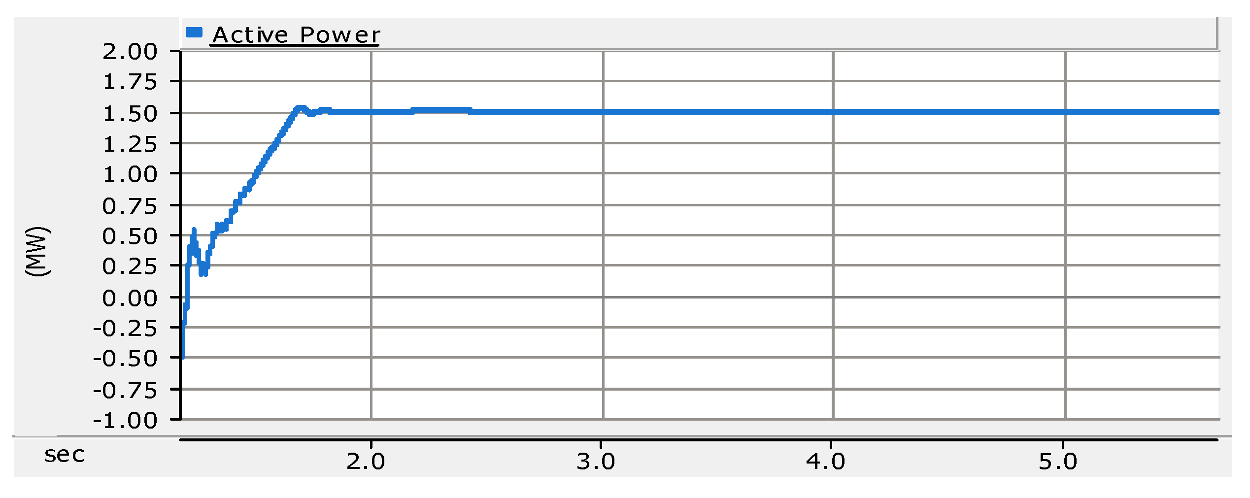
3. Normal Operation Results

The output results of active power, reactive power, voltage and currents were obtained during normal operating conditions. It is shown in Figure 2 that the output current is within [−1, 1] per unit, having a base current of 1450 A at the rated wind speed of 13 m/s. Figure 3 shows the output voltage, which is within [−0.75, 0.75] in p.u., with a base voltage of 690 V. The active power and reactive power outputs are also given in Figure 4 and Figure 5, which are 1.5 MW and 0 MVar (as it was set as zero in the model for ease of understanding), respectively.

4. Analysis of Unsymmetrical Fault

Regarding an unsymmetrical fault of type single phase (phase B) to ground, applied at a distance of 5 km on the line, the DFIG would react to this fault more strongly than if the same fault occurred at 10 km on the line. The duration of the fault is set to 1 s. The output current is shown in Figure 6. It is shown that the current on phase B increased to three to four times its normal current. The other phase’s current also increased. All of these changes have effects on the stator current, and, due to magnetic coupling between the stator and rotor, the rotor current also changes. Thus, the stator current and rotor current both will increase. The result is shown in Figure 7.
During the increases in the fault stator and rotor current, mechanical disturbance will also be produced. Moreover, the generator will become unstable due to the increase in the current of the stator and rotor from the specific value. Similarly, the back-to-back converters of the DFIG are made up of power electronic devices and switches, which are expensive and vulnerable to damage due to different types of faults. A limit is pre-set for them in which the maximum current should not be exceeded; here, the limit is set to 1.2 p.u. of its current. The current on phase B passing through the power electronic devices is shown in Figure 8. It is illustrated in the figure that the amount of current exceeds its predefined value, which is injurious to these DFIG converters (electronic devices and switches).

5. Crowbar Protection

Crowbar protection is one of the most important types of protection to protect the converters from faults. In this type of protection, whenever a fault occurs, the crowbar protection circuit will be operated, which provides an alternative path for the rotor current. Thus, it will short-circuit the rotor-side converter and decrease the rotor current that passes through the converter. When the fault clears, the crowbar circuit will be deactivated and the rotor current will return to its normal value. The crowbar protection circuit consists of IGBT switches, a resistor and diodes. A high value of the resistor causes high voltage and a low value of the resistor causes a high rotor current and low voltage, so there is a tradeoff when choosing the value. In this circuit, a resistor with a value of 1 mΩ is used. The circuit is shown in Figure 1.

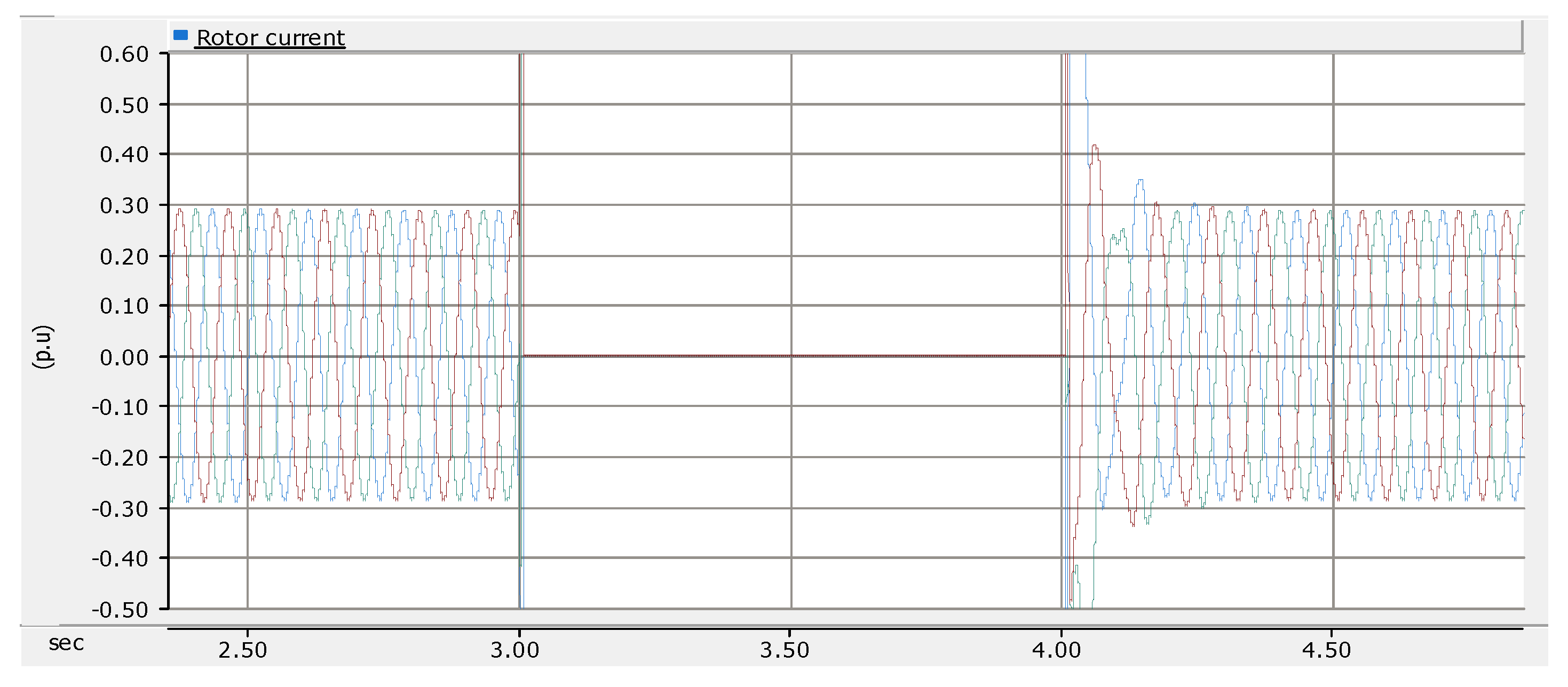
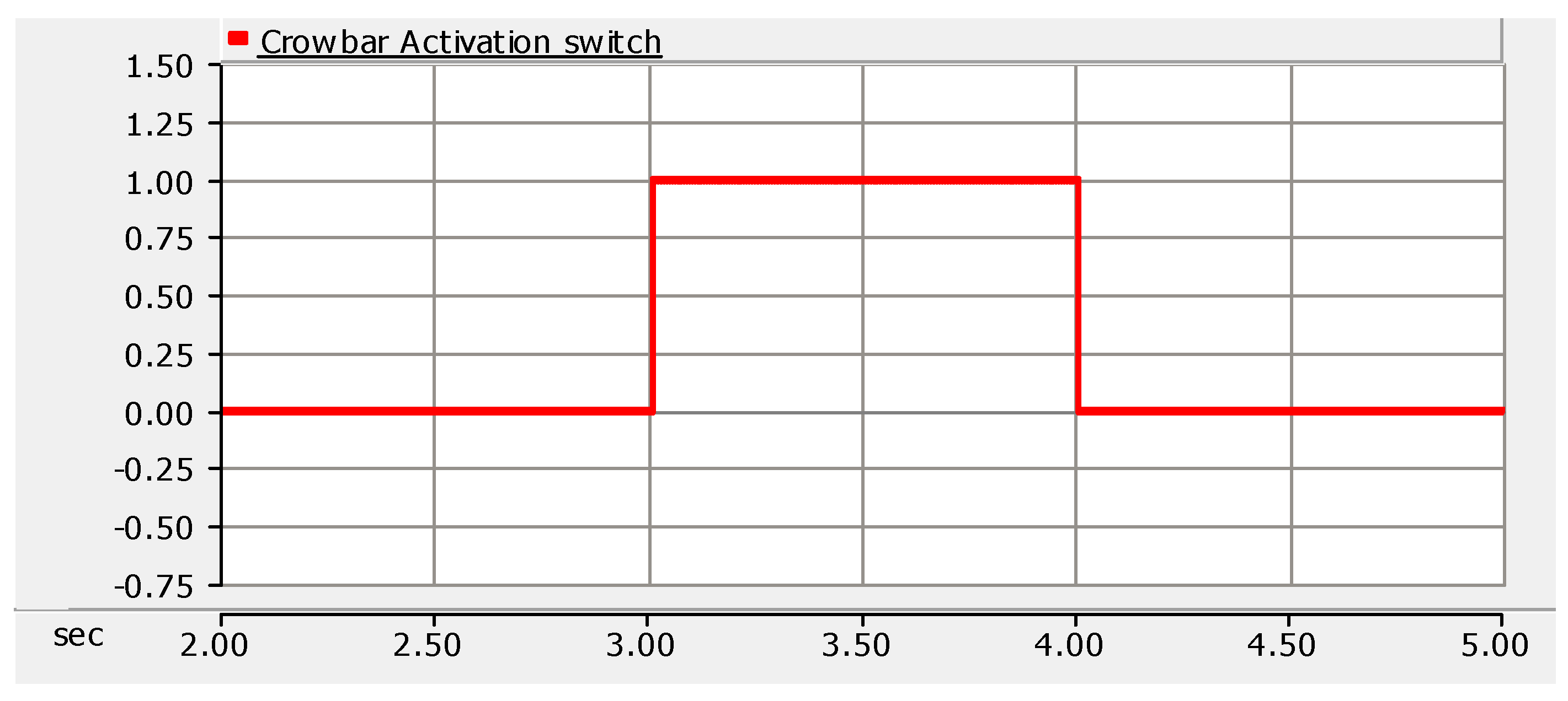
6. Simulation Results When Crowbar Activates

When the crowbar circuit activates during the fault, all of the rotor current will be bypassed and it travels towards the crowbar circuit instead of the rotor as shown in Figure 9. Thus, during the whole fault duration, the current passing towards the rotor-side converter will be zero as shown in Figure 10, and it passed towards the crowbar circuit as shown in Figure 11. The rotor-side converter disconnects from the rotor and the DFIG is converted into an induction generator. Then, this generator absorbs the reactive power from the grid for the fault duration. When the fault ends, the crowbar will be deactivated as seen in Figure 12, so that the rotor-side converter connects to the rotor again, and the induction generator will again change into a doubly fed induction generator, which will then generate the active and reactive power for which it is designed, i.e., here, in this paper, it is designed to generate 0 MVAR. The output results of active power and reactive power are shown in Figure 13 and Figure 14 respectively. In order to examine the behavior and operation of the crowbar circuit, the following figures are shown. The time for crowbar operation is equal to the duration of the fault.

7. Conclusions

This paper presents a simulation model for the asymmetrical fault analysis and protection of a 1.5 MW DFIG wind turbine converter in EMTDC/PSCAD. A single line to ground fault is created and we then analyze its behavior in the DFIG and its converters. The crowbar protection scheme is presented and we then check the impact of overcurrents on the DFIG. The crowbar protection method has better performance with various grid faults, and this can be an effective method to eliminate faults and transients.

Author Contributions

Conceptualization, M.U.K. and H.A.K.; methodology, M.U.K.; software, M.U.K.; validation, M.U.K.; formal analysis, M.U.K. and H.A.K.; investigation, M.U.K.; resources, M.U.K. and H.A.K.; data curation, M.U.K.; writing—original draft preparation, M.U.K. and A.K.; writing—review and editing, M.U.K., and H.F. All authors have read and agreed to the published version of the manuscript.

Funding

The research receive no external funding.

Institutional Review Board Statement

Not applicable.

Informed Consent Statement

Not applicable.

Conflicts of Interest

The authors declare no conflict of interest.

References

  1. Davoudi, M.; Sadeh, J.; Davoudi, M. Analysis of DFIG During Unsymmetrical Grid Fault by Using Crowbar Circuit. In Proceedings of the 2019 Iranian Conference on Renewable Energy & Distributed Generation (ICREDG), Tehran, Iran, 11–12 June 2019; pp. 1–6. [Google Scholar]
  2. Fateh, F.; White, W.N.; Gruenbacher, D. A Maximum Power Tracking Technique for Grid-Connected DFIG-Based Wind Turbines. IEEE J. Emerg. Sel. Top. Power Electron. 2015, 3, 957–966. [Google Scholar] [CrossRef]
  3. Hu, J.; Huang, Y.; Wang, D.; Yuan, H.; Yuan, X. Modeling of Grid-Connected DFIG-Based Wind Turbines for DC-Link Voltage Stability Analysis. IEEE Trans. Sustain. Energy 2015, 6, 1325–1336. [Google Scholar] [CrossRef]
  4. Ma, J.; Zhao, D.; Yao, L.; Qian, M.; Yamashita, K.; Zhu, L. Analysis on application of a current-source based DFIG wind generator model. CSEE J. Power Energy Syst. 2018, 4, 352–361. [Google Scholar] [CrossRef]
  5. Tang, W.; Hu, J.; Chang, Y.; Liu, F. Modeling of DFIG-Based Wind Turbine for Power System Transient Response Analysis in Rotor Speed Control Timescale. IEEE Trans. Power Syst. 2018, 33, 6795–6805. [Google Scholar] [CrossRef]
  6. Rostami, M.; Madani, S.M.; Ademi, S. Sensorless Closed-Loop Voltage and Frequency Control of Stand-Alone DFIGs Introducing Direct Flux-Vector Control. IEEE Trans. Ind. Electron. 2020, 67, 6078–6088. [Google Scholar] [CrossRef]
  7. Zhu, M.; Li, W.; Liang, X.; Xu, S.; Zhou, B.; Shen, Y. Stepwise Voltage Drop and Transient Current Control Strategies to Enhance Fault Ride-Through Capability of MMC-HVDC Connected DFIG Wind Farms. IEEE Trans. Power Syst. 2021, 36, 2127–2137. [Google Scholar] [CrossRef]
  8. Sun, T.; Chen, Z.; Blaabjerg, F. Transient Analysis of Grid-Connected Wind Turbines with DFIG After an External Short-Circuit Fault. In Proceedings of the Nordic Wind Power Conference, CD-ROM, Gøteborg, Sweden, 1–2 March 2004; pp. 1–6. [Google Scholar]
  9. Swain, S.; Ray, P.K. Fault Analysis in a Grid Integrated DFIG Based Wind Energy System with NA CB_P Circuit for Ridethrough Capability and Power Quality Improvement. Int. J. Emerg. Electr. Power Syst. 2016, 17, 619–630. [Google Scholar] [CrossRef]
  10. Li, D.; Cai, M.; Yang, W.; Wang, J. Study of Doubly Fed Induction Generator Wind Turbines for Primary Frequency Control. In Proceedings of the 2020 IEEE 4th Conference on Energy Internet and Energy System Integration (EI2), Wuhan, China, 30 October–1 November 2020; pp. 2690–2695. [Google Scholar]
Figure 1. Diagram of 1.5MW WT system under line to ground fault with crowbar protection.
Engproc 20 00041 g001
Figure 2. Output current.
Engproc 20 00041 g002
Figure 3. Output voltage.
Engproc 20 00041 g003
Figure 4. Active power.
Engproc 20 00041 g004
Figure 5. Reactive power.
Engproc 20 00041 g005
Figure 6. Output current.
Engproc 20 00041 g006
Figure 7. Rotor current.
Engproc 20 00041 g007
Figure 8. Phase B rotor converter current.
Engproc 20 00041 g008
Figure 9. Rotor current.
Engproc 20 00041 g009
Figure 10. Phase B rotor converter current.
Engproc 20 00041 g010
Figure 11. Crowbar current.
Engproc 20 00041 g011
Figure 12. Crowbar activation switch.
Engproc 20 00041 g012
Figure 13. Active power.
Engproc 20 00041 g013
Figure 14. Reactive power.
Engproc 20 00041 g014
Publisher’s Note: MDPI stays neutral with regard to jurisdictional claims in published maps and institutional affiliations.

