Proceeding Paper

Detection of Velocity Based on Change in the Apparent Size †

by
Ashok Kumar Sivarathri
*,
Amir Mohammad
and
Pankaj Popatrao Shitole
Indian Institute of Technology Mandi, Kamand, Mandi, Himachal Pradesh 175005, India
*
Author to whom correspondence should be addressed.
Presented at the 7th Electronic Conference on Sensors and Applications, 15–30 November 2020; Available online: https://ecsa-7.sciforum.net/.
Eng. Proc. 2020, 2(1), 27; https://doi.org/10.3390/ecsa-7-08158
Published: 2 December 2020
(This article belongs to the Proceedings of 7th International Electronic Conference on Sensors and Applications)

Abstract

:
This article discusses a concept for developing a vision-based sensing system for measuring the velocity of an object which is based on the concept of apparent size. Objects at a finite distance from the eye look smaller than their real dimension. Movement of the object causes to change in its apparent size. In this work a mathematical relation is obtained which relates infinitesimal change in apparent size to the infinitesimal change in spatial coordinates of the object in the form of an ordinary differential equation. A mechanical device is fabricated for measuring the apparent size. Then by knowing the change in apparent size due to motion, change in displacement is calculated. Experiments were conducted to measure the average velocity of regular shaped object based on the change in its apparent size due to its motion. The average magnitude of error between average velocity calculated from the change in apparent size through the equation and from the actual displacement is about 2% and it is varying in between 0% and 5%. Results show the possibility to develop a vision sensor system to measure the velocity of objects by using high-speed cameras when the real size of the object is known and also it may be possible to develop vision velocity sensors for mobile robot applications.

1. Introduction

Sensors play a key role in mechatronic and robotic systems [1]. Velocity is one of the important physical quantities which has to be continuously measured in various mechanical systems such as robotic systems. For example, an end effectors position and velocity have to be continuously monitored for the successful operation of the robot [2,3]. Various sensors are available as internal (Encoders, LVDT (Linear Variable Differential Transformer), Tachometer, Hall effect sensor and etc.) and external (Proximity, Microwave, Ultrasonic, Vision sensors and etc.) sensors for positioning and velocity measurement in mechanical systems [2]. In this article, we describe a concept to develop a vision-based sensing system for measuring the velocity of the objects which is based on the apparent size of a moving object.

1.1. Vision-Based Velocity Sensors

Vision/Camera-based sensors have been reported in the literature for general and robotic applications [1,3,4,5]. Vision-based sensing systems are developed for positioning, tracking of external objects [3,6]. In vision sensing systems, change in spatial position of the object is determined by change in its coordinates in the image of the camera [4,6,7]. Change in the relative position of the object in the image is mapped to the real distance travelled by the object and hence the velocity of the object is obtained [4,6]. This technique can be applied to estimate speed of the road vehicles [7]. However, this technique may not work if the object is moving exactly along the optical axis of the camera where change in the relative position of the object in the image is negligible. Depth of the object from the camera sensor changes in this case which can be estimated by using a pair of images of the object where the appropriate line segments from the images are used to obtain the depth [8,9]. However, these are not real-time techniques. Calculation of real-time depth of an object is impossible with the single image [10]. Stereo camera systems (multiple camera sensors) are used to measure the depth of the object, thereby estimating instantaneous depth velocity of the object [10,11]. In all of the above studies, detection of the object velocity is based on the calculation of change in the relative position of the object in the image of the camera and size of the object does not play any role. The current article presents an another possible way to estimate the depth velocity of the object, even when it travels along the optical axis of the camera. This is based on the concept of change in the apparent size of an object due to its motion.

1.2. Apparent Dimesion of an Object

Objects at a distance look smaller than their real dimensions. For example, size of the moon can be fit into a coin at a distance near to the eye. This is called apparent size and is always less than the original dimension of the object [12]. They look smaller because of the decrease in the angle made by the light rays at the eye coming from the boundary of the object which is shown in Figure 1 The apparent size of an object can be measured anywhere in-between object position and the eye.
So when the object is in linear motion without rotation, its apparent size varies at a fixed measurement point which is the basis for the current work. Rate of change of apparent size is an indication of the rate of change of position of the object which is also discussed in the literature [12]. Thus the rate of change of apparent size of an object is directly related to the instantaneous velocity of the object. Depth velocity of objects can be estimated by using stereo camera system as discussed where the object is considered to be a point object [3,10]. In this work, we present another possibility to estimate instantaneous velocity an object in real-time with a single lens camera when the real size of the object is known and dimensions of the object play crucial role in the present technique.

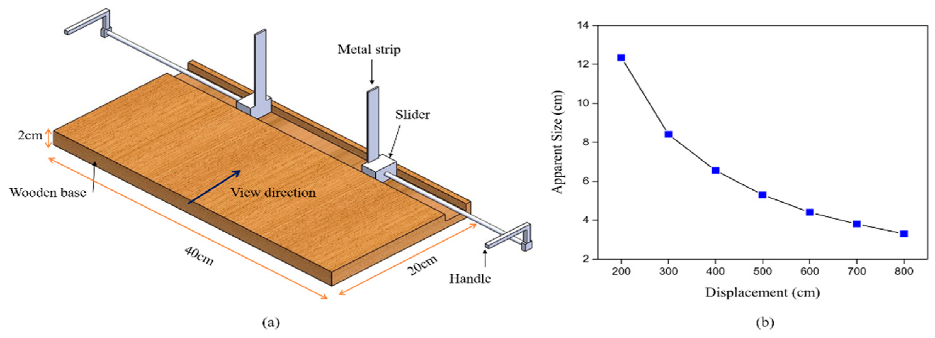
2. Mathematical Analysis

So, from the previous discussion it is clear that the apparent size of the object changes when it is in motion. All we need is to find the infinitesimal change in the displacement for an infinitesimal change in the apparent size of the object. Consider a two dimensional object moving in the x y coordinate system as shown in Figure 2a, edges a b and e f are parallel to the x and y axes which are the real sizes of the object along the respective axes. Let the center of mass of the object displace d x and d y with initial coordinates ( x , y ) without rotation of the object.
For this analysis it is assumed that the axis of the lens of the eye passes through the mid-point of the edge. First let us consider displacement along the x axis, Figure 2b shows the two instances of the object making a d x movement. It can be seen from Figure 2b that the apparent size of the edge e f is decreased for a positive movement of d x . The apparent size of the edge e f is measured along y at a distance ρ x from the eye. As shown in Figure 2b, d r y is the change in the apparent size of the edge e f and r y is the apparent size. From geometric analysis of this situation we can arrive at the following ordinary differential equation.
R y ρ x r y 2 d r y d x d r y r y = 1 ,
When d r y is positive, the object is reaching the eye and if it is negative then the object is going away from the eye. Based on this direction velocity can be found. Similarly, considering a displacement of d y the in the y direction gives the following ordinary differential equation.
R x ρ y r x 2 d r x d y d r x r x = 1 ,
where, R x is the real size or length of the edge a b along the x axis, ρ y is the distance from the eye for measuring the apparent size of the edge and r x is the apparent size of the edge at a particular instant of time. This can be expanded to the 3-Dimensional (3-D) case by considering a 3-D object moving in an x y z coordinate system. In this case, we will have 2-Dimensional (2-D) projections of the object on three mutually perpendicular planes. The following ordinary differential equations relate the change in the apparent size of the edges considered from the surfaces of the object, which are parallel to the three mutually perpendicular planes ( x y , y z , x z ), to the change in spatial coordinates of the object in three mutually perpendicular coordinates ( x , y , z ).
R x y ρ z r x y 2 d r x y d z d r x y r x y = 1 ,
R x z ρ y r x z 2 d r x z d y d r x z r x z = 1 ,
R y z ρ x r y z 2 d r y z d x d r y z r y z = 1 ,
where, R x y , R x z and R y z are real sizes of line elements calculated from orthotropic projections of the edges of the object considered from the faces of the object which are parallel to the x y , x z and y z planes. ρ x , ρ y and ρ z are the measurement distances of apparent sizes from the eye in x , y and z directions, respectively. r x y , r x z and r y z are calculated from apparent sizes of the object on three mutually perpendicular planes. This can be understood by visualizing a cube of edge length l is moving in a x y z coordinate system such that three of its faces are parallel to three mutually perpendicular planes. Consider a line element/edge from a face which is parallel to the x y plane and a diagonal line is one of the possibilities. If the cube is moving in the x y plane without rotation, change in apparent size of the diagonal is zero in that plane which suggests that its velocity is zero along the z direction. Apparent sizes of the diagonal lines of the faces parallel to the x z and y z planes change due to this motion and hence components of velocities along x and y directions can be found. Equations (3)–(5) are expressed in the following matrix form. These are obtained by dividing the Equations (3)–(5) by change in time. The selected edge/line has to be perpendicular to the optical axis which is a limitation of this technique.
[ V x V y V z ] = [ R y z ρ x r y z 2 + r y z d r y z 0 0 0 R x z ρ y r x z 2 + r x z d r x z 0 0 0 R x y ρ z r x y 2 + r x y d r x y ] [ d r y z d t d r x z d t d r x y d t ] ,
where V x = d x d t , V y = d y d t and V z = d z d t are velocities of the object in x , y and z directions, respectively, and d r y z d t , d r x z d t and d r x y d t are rates of change of apparent sizes.

3. Experiments and Discussion

Figure 3a shows the Solidworks model of the mechanical device for measuring the apparent size of the object. The apparent size of the object is fit into both metal strips by manually moving sliders with the help of handles. A rectangular shaped (112 cm length, 10 cm width and 1 cm thickness) wooden object was chosen for the experiments. The longest edge of the object was kept parallel to the y axis and its apparent size was measured for different positions by moving it along the x direction which is along the axis of the lens of the eye or viewing direction of the device. During experimentation it was ensured that the centerline of the device/axis of eye is passing through the center of the object. Distance from the eye to the measurement point of the device was 24.5 cm which is ρ x and the real size ( R y ) of the object was 112 cm. Figure 3b shows the variation of the apparent size of the object with respect to distance from the measurement point. It can be clearly seen from the Figure 3b that apparent size is a non-linear function of the displacement which is a well-known fact [12]. For the velocity measurements, object is moved slowly away from the device simultaneously measuring the apparent size and time at two instances. Then from the change in the apparent size displacement of the object is calculated and velocity is obtained by dividing it with the change in time. Table 1 shows the average velocity of the object calculated form the change in apparent size and the actual average velocity obtained from the repeated experiments. Accurate measurement of displacement will ensure the accurate velocity.
Figure 4 shows the variation of magnitude of the error with change in the displacement of the object. It can be seen that it is varying in between 0% and 5% and there may not be any specific variation with the displacement of the object. Accurate measurement of apparent size by the precise instrument may decrease the error magnitude and high-speed camera may enable us to measure the change in apparent size accurately.
So measuring the infinitesimal change in the apparent size will enable us to estimate the instantaneous velocity of the object if the real size of the object is known. Thus it may be possible to develop a vision-based sensing system for measuring object velocity in three directions ( x , y , z ), two components can be obtained from the change in the relative position of the object in the image of the camera [4] and one from the change in the apparent size of the object.

4. Conclusions

This concept may show another possibility for measuring the real-time instantaneous velocity of an object from the change in its apparent dimension when the real size of the object is known. A mechanical device for measuring the apparent size is fabricated and the average velocity of an object is measured from the change in its apparent size. A 2% of average error magnitude was observed between actual average velocity and the one calculated from the change in apparent dimension. The error magnitude varied in between 0% and 5%. With this technique, it may be possible to develop a vision-based sensing system for mobile robot applications for measuring velocity of the robot. It may also possible to measure the acceleration of the object in real-time.

Acknowledgments

I acknowledge the support from the Mechanical Workshop, Indian Institute of Technology Mandi.

Conflicts of Interest

The authors declare no conflict of interest.

References

  1. Saha, Subir Kumar. Introduction to Robotics; Tata McGraw-Hill Education: Chennai, India, 2014. [Google Scholar]
  2. Niku, Saeed B. Introduction to Robotics: Analysis, Systems, Applications; Prentice hall: Upper Saddle River, NJ, USA, 2001; Volume 7. [Google Scholar]
  3. Veiga Almagro, C.; Di Castro, M.; Lunghi, G.; Marín Prades, R.; Sanz Valero, P.J.; Pérez, M.F.; Masi, A. Monocular Robust Depth Estimation Vision System for Robotic Tasks Interventions in Metallic Targets. Sensors 2019, 19, 3220. [Google Scholar] [CrossRef] [PubMed]
  4. Echigo, T. Apparatus and Method for Detecting a Velocity of a Moving Object. U.S. Patent No. 5,771,485, 23 June 1998. [Google Scholar]
  5. Gomez-Gonzalez, S.; Nemmour, Y.; Schölkopf, B.; Peters, J. Reliable Real-Time Ball Tracking for Robot Table Tennis. Robotics 2019, 8, 90. [Google Scholar] [CrossRef]
  6. Song, H.; Chen, Y.; Gao, Y. Velocity Calculation by Automatic Camera Calibration Based on Homogenous Fog Weather Condition. Int. J. Autom. Comput. 2013, 10, 143–156. [Google Scholar] [CrossRef]
  7. Doğan, S.; Temiz, M.S.; Külür, S. Real time speed estimation of moving vehicles from side view images from an uncalibrated video camera. Sensors 2010, 10, 4805–4824. [Google Scholar] [CrossRef] [PubMed]
  8. He, L.; Yang, J.; Kong, B.; Wang, C. An Automatic Measurement Method for Absolute Depth of Objects in Two Monocular Images Based on SIFT Feature. Appl. Sci. 2017, 7, 517. [Google Scholar] [CrossRef]
  9. Torralba, A.; Oliva, A. Depth estimation from image structure. IEEE Trans. Pattern Anal. Mach. Intell. 2002, 24, 1226–1238. [Google Scholar] [CrossRef]
  10. Kang, M.J.; Lee, C.H.; Kim, J.H.; Huh, U.Y. Distance and velocity measurement of moving object using stereo vision system. In Proceedings of the 2008 International Conference on Control, Automation and Systems, Seoul, Korea, 14–17 October 2008; pp. 2181–2184. [Google Scholar] [CrossRef]
  11. Wei, Z.; Zhao, K. Structural parameters calibration for binocular stereo vision sensors using a double-sphere target. Sensors 2016, 16, 1074. [Google Scholar] [CrossRef] [PubMed]
  12. Herstein, R.J.; Walker, M.L. Perception of vehicle speed as a function of vehicle size. Bull. Psychon. Soc. 1993, 31, 566–568. [Google Scholar] [CrossRef]
Figure 1. Apparent size of an object at a finite distance from the eye.
Engproc 02 00027 g001
Figure 2. (a) A 2-D object (polygon) in the x y coordinate system; (b) change in apparent size of the edge e f for a d x movement along the x axis.
Engproc 02 00027 g002
Figure 3. (a) Mechanical device for measuring the apparent size; (b) variation of apparent size of an object with displacement.
Engproc 02 00027 g003
Figure 4. Variation in the error magnitude with the change in displacement of the object.
Engproc 02 00027 g004
Table 1. Comparison of actual displacement, average velocity and calculated displacement, average velocity.
S.NoExperimental Displacement of the Object (cm)Displacement Calculated from the Equation 1 (cm) Experimental Average Velocity (cm/s)Average Velocity Calculated by using Equation 6 (cm/s)Error Magnitude (%)
1.−100−104.57−20−20.9144.57
2.−200−200.14−20−20.014 0.073
3.−300−295.81−23.076−23.7541.399
4.−400−401.80−16−16.0720.45
5.−500−519.89−15.15−15.753.95
6.−600−609.87−15−15.241.6
Publisher’s Note: MDPI stays neutral with regard to jurisdictional claims in published maps and institutional affiliations.

