1. Introduction
One of the main challenges of the European Demonstration Fusion Power Reactor (EU-DEMO) is being able to achieve long plasma operation and demonstrate the net electric output in an industrial scale [
1,
2,
3]. To achieve this goal, DEMO must be more oriented towards electricity production, hence the Balance of Plant (BoP) must be considered as an essential system, which is a vital extension to ITER since ITER is not designed to generate any electrical power [
4]. BoP is envisaged to extract the pulsed thermal power generated by plasma from the PHTS and transport the power to the PCS [
5].
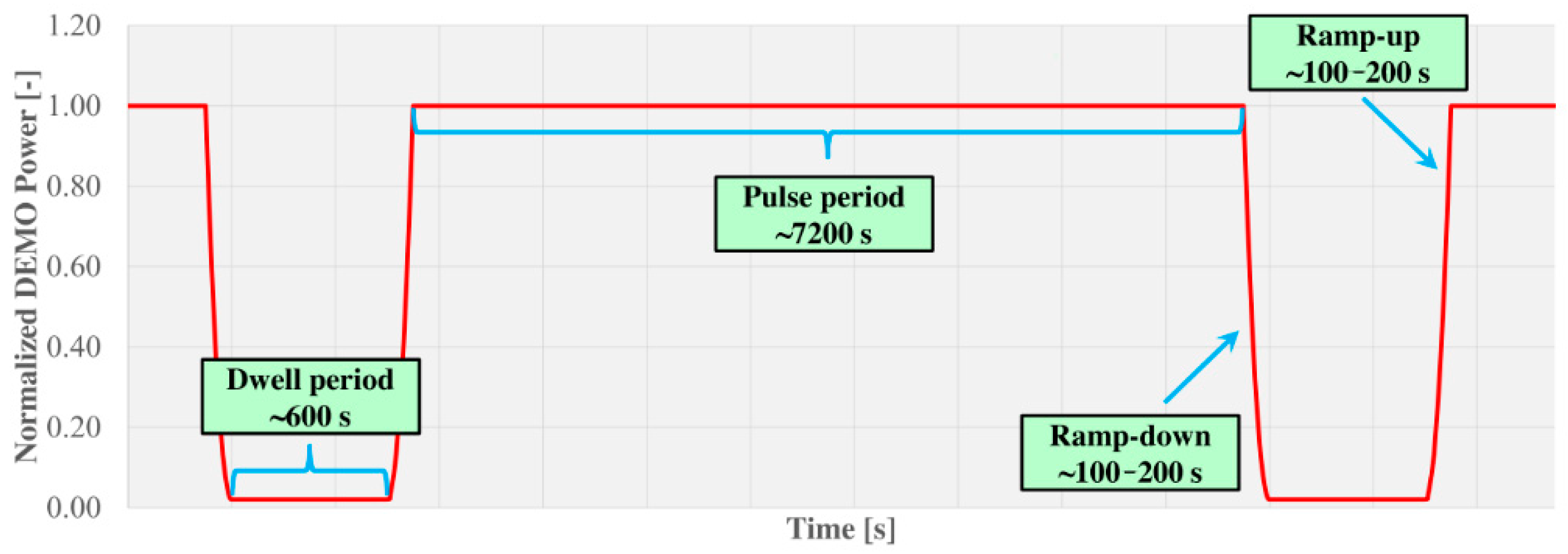
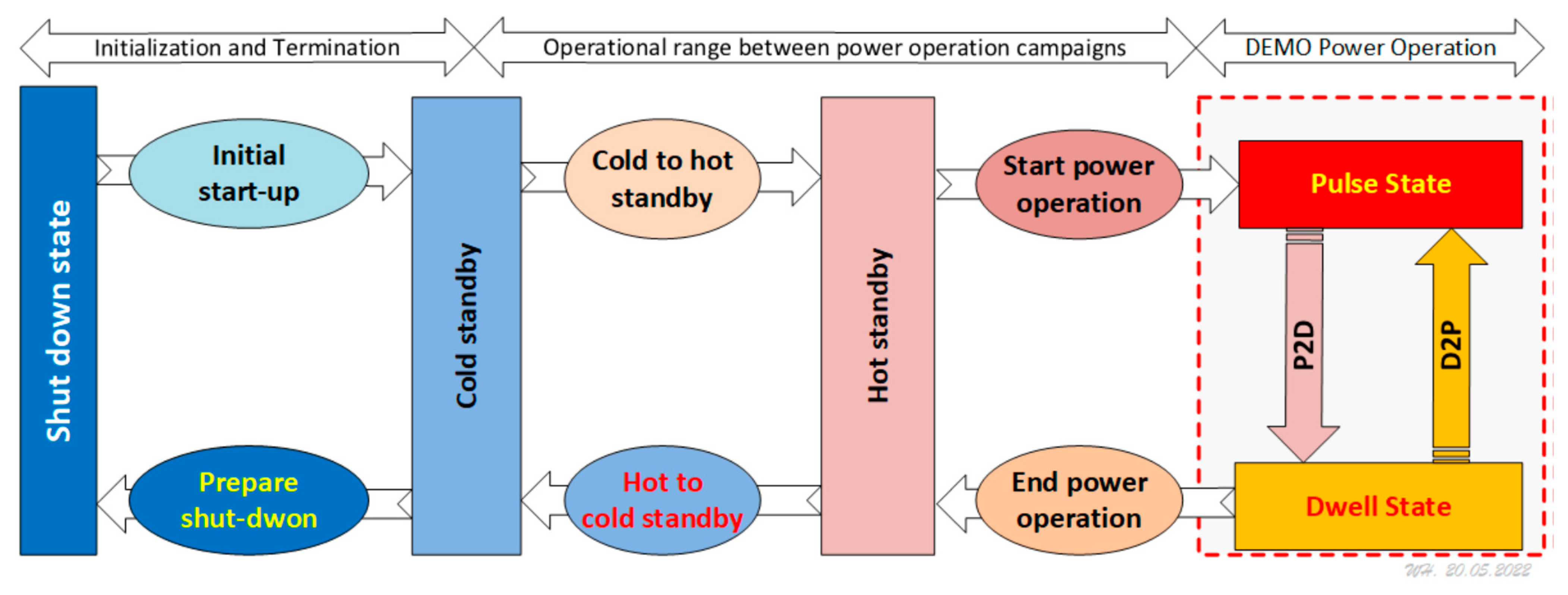
The intrinsic challenge of a heat transport chain in a Tokamak-based DEMO plant is the intermittent fusion plasma operation as a primary heat source to the Plant Electrical System, in which pulse operation lasts about 7200 s and the dwell operation period lasts about 600 s, as depicted in
Figure 1 [
6]. The HCPB-BoP will be capable of providing stable thermal power to the PCS throughout the intermittent plasma operational phases (pulse and dwell) and its realization requires an energy storage system (ESS) integrated into the IHTS.
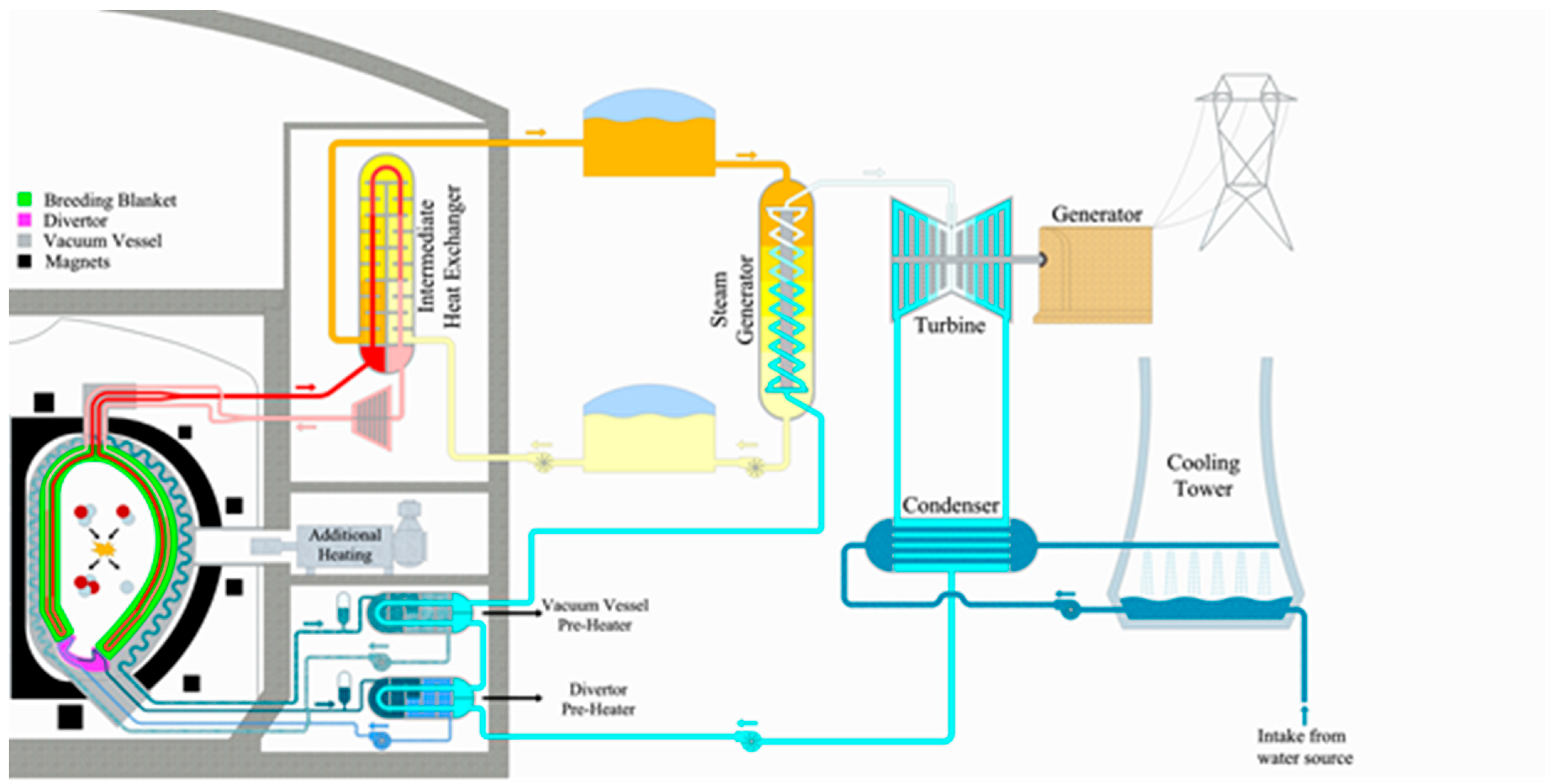
Various variants of the EU-DEMO BoP are under evaluations focusing on the cycling performances of the components, the efficiency, integration possibility, and safety. The variants are classified as either Direct Coupled Design or Indirect Coupled Design (ICD). Among the proposed solutions, the ICD with an large energy storage system (ESS) based on commercial systems already operating in concentrating solar power plants are the most robust [
4] (see
Figure 2 from [
7]). Thus, this HCPB BoP ICD option was selected as the reference variant for the next step of DEMO development, the so-called Conceptual Design Phase. Achievements on the optimization of the BoP system have been reported in [
5,
7,
8,
9] comprising the system conceptual design of the IHTS with the molten salt loop [
8,
9] and the principal design of the He/MS heat exchanger (He/MS HX) [
7]. The critical issue is firstly related to the interface of PHTS and IHTS which are connected with a He/MS HX, and between IHTS and PCS which are connected with a MS Steam Generator [
4].
The main challenges of the thermodynamic and heat transport processes of the IHTS (ESS) system are:
The helium inlet temperature to the breeding blanket shall be maintained stable during both pulse and dwell operation. Since during dwell time PHTS extracts only 1% of the full nominal power, the cooling of the PHTS in dwell needs a sensible regulation of the IHTS-ESS;
The fast transients of pulse-to-dwell ramp-down and dwell-to-pulse ramp-up that take place within 100–200 s requires fast response of the ESS [
10];
Not only the normal power generation modes throughout pulse and dwell phases shall be functional, but also the preparation, standby, and shutdown modes shall be considered;
The heat transfer characteristics, fabrication, and material fatigue feature of the He/MS HX shall be assessed in industrial and experimental trials.
The interaction of the different systems must be investigated and optimized. Here, the expertise of KIT on helium system operation (HELOKA-HP [
11] and KATHELO [
12]), as well as the expertise in the high-temperature molten salt field (LIVE [
13,
14]) are favorably combined within the HELOKA-US project. The conceptual design and technical specification of the Phase 1 components are completed. Engineering layout design and construction will be started very soon.
The construction conception the HELOKA-US facility is presented in
Section 2. The design features and operational modes are described in
Section 3, including the loop design and components as well as the operation modes considered.
Section 4 provides the numerical simulations performed to establish the conceptual design of HELOKA-US as in Phase 1. Finally, the conclusions and coming steps are providing in
Section 5.
2. Construction Conception of the Project
The new-build HELOKA-US system bears the aim to investigate the HCPB BoP ICD concept with a molten salt loop as the IHTS with ESS function for the helium-cooled DEMO variant. The power scaling is 1:1000 of one of the eight PHTS circuits, corresponding to 260 kW of nominal power. The total height of the molten salt loop is about 9 m, which is about ¼ of the DEMO IHTS vertical dimension. The whole experimental facility will be built in two phases, as depicted in
Figure 3.
First, the tags of the loops and system and tags of the component in the ES are given in
Table 1.
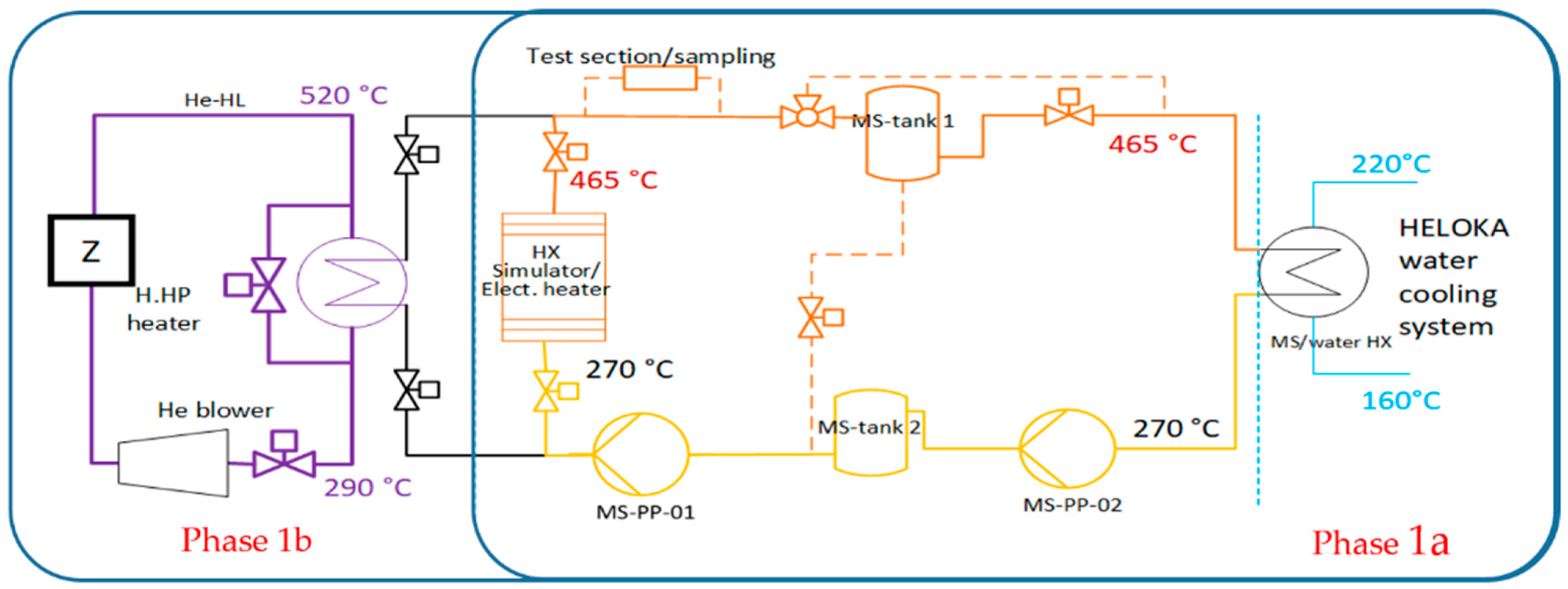
Phase 1: The energy storage (ES) loop using HITEC as molten salt coupled with the HELOKA-HP helium loop will be built. This phase is split in two sub-phases: Phase 1a and Phase 1b. The heating source in Phase 1a is an electrical heater supplying 260 kW power, while in Phase 1b, the heated helium from HELOKA-HP will provide the heat source via a He/MS HX, which replaces the electrical heater used in Phase 1a. The heat sink in both Phases 1a and 1b is the HELOKA, an intermediate high-temperature high-pressure water loop (WHT) that is coupled with a water-cooling system (WCS) in normal pressure. A WHT can be operated up to 46 bar, and thus ensures a waterside coolant temperature range of 160–220 °C, which is above the solidification temperature (142 °C) of the HITEC molten salt.
Phase 2: The ES loop will be coupled to a representative DEMO-PHTS helium circuit driven by a scaled-down DEMO prototypical blower.
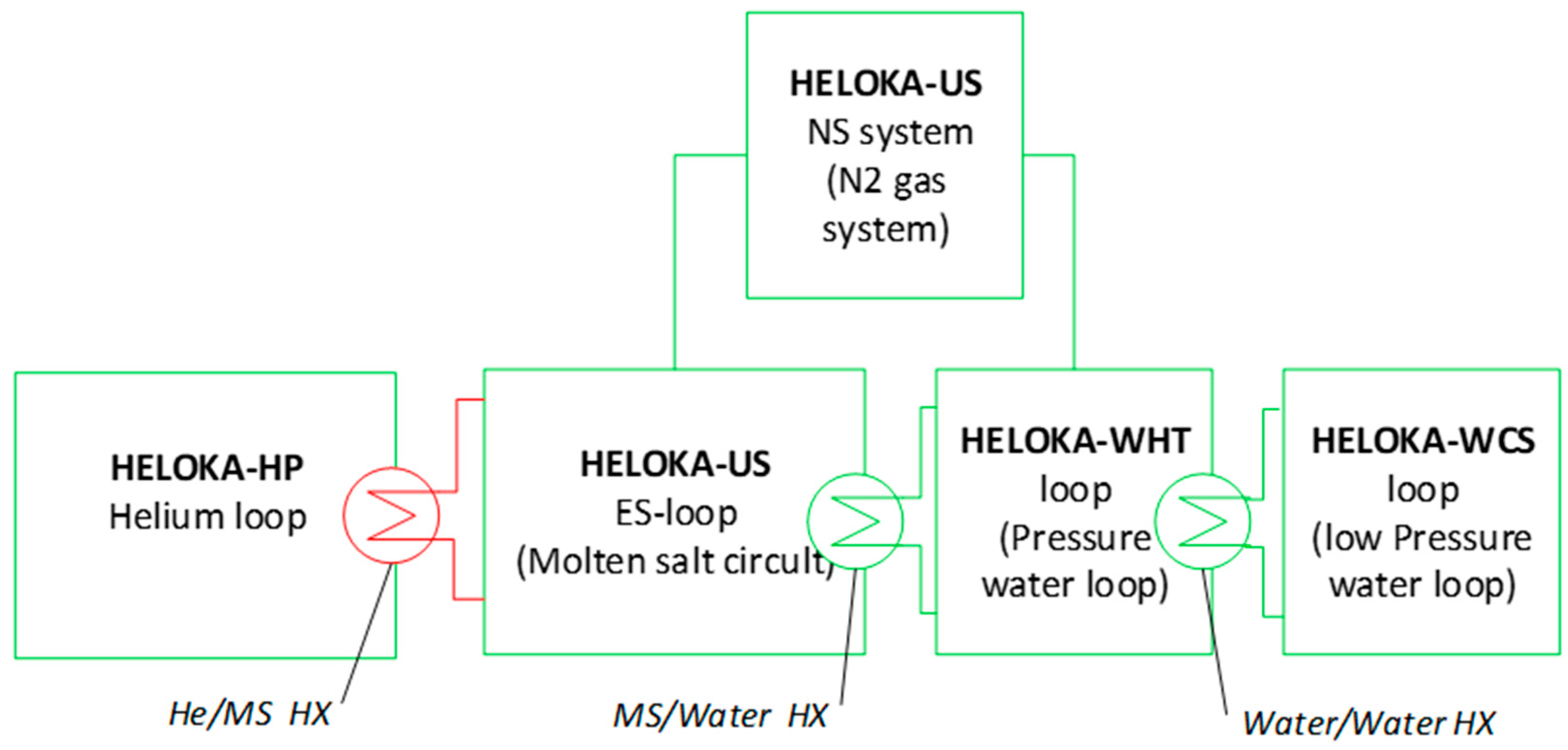
The coupling of the HELOKA-HP loop, ES loop, WHT system, and WCS at the completion of Phase 1b is depicted in
Figure 4. HELOKA-HP, WHT, and WCS are existing infrastructure, as well as the power supply system and the data acquisition and control system, which are the infrastructure of HELOKA-HP. The main focus for Phase 1a is the design and building of the ES and cover gas (N
2) system (NS), the coupling between ES and WHT with a new built MS/water heat exchanger, as well as the coupling WHT-WCS with a water/water heat exchanger. The ES loop and WHT system are connected with NS, which serves as cover gas and pressure regulation for the ES loop and for the pressure control for the WHT system.
3. Design Features and Operational Modes of HELOKA-US
3.1. Molten Salt Properties
The HITEC salt with molar ratio of KNO
3:NaNO
3:NaNO
2 in 44:7:49 is selected as the heat transfer fluid for the ES loop following the DEMO HCPB BoP ICD specifications. Its chemical and physical behavior is well-studied in the field of concentrated solar power plants [
15,
16,
17]. The strongest argument for the HITEC is its low solidification temperature of 142 °C, which enables it to be used as a heating source of low coolant temperature, e.g., in the steam generator. The HITEC is chemically stable under N
2 gas at least up to 465 °C and can even be applied briefly at higher temperatures up to 538 °C.
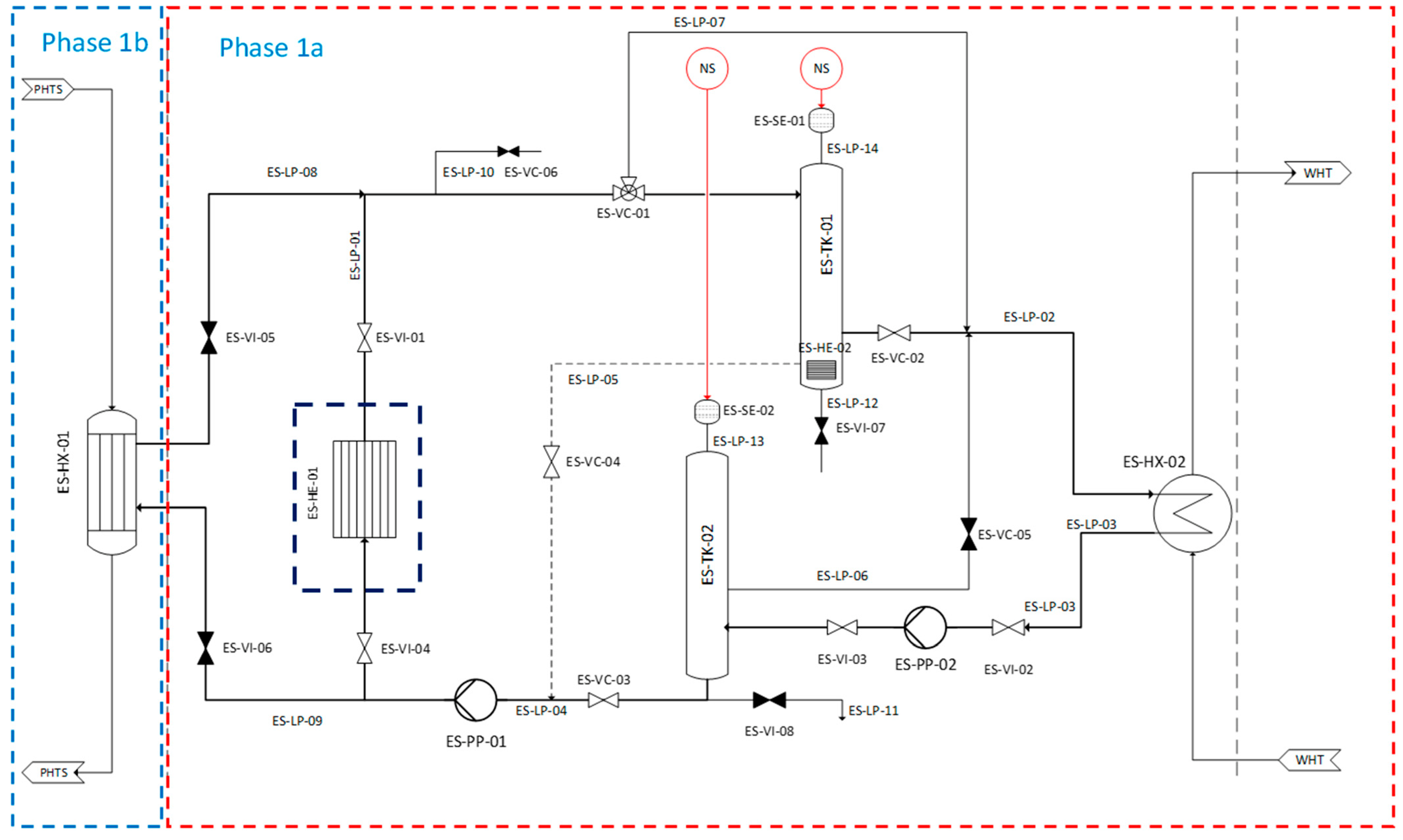
3.2. Loop Design and Components
ES loop: The Pipe and Instrumentation Diagram of the HELOKA-US is depicted in
Figure 5. A two-tank system in direct connection with the main loop is applied. A list of the main components in the ES loop is given as follows:
Two tanks (TK): ES-TK-01 and ES-TK-02 (DN450, each tank, ~0.8 m³);
Two pumps (PP): ES-PP-01 and ES-PP-02 (2.5 m³/h, total developed head: 15–20 m);
One external electrical heater (HE): ES-HE-01 (~260 kW);
One internal electrical heater in ES-TK-01: ES-HE-02 (~30 kW);
Six control valves (VC): ES-VC-01 to ES-VC-06 (DN25, DN33, DN40);
Eight isolation valves (VI): ES-VI-01 to ES-VI-08;
Two MS separators (SE) above the tanks: ES-SE-01 and ES-SE-02;
Pipelines (LP): ES-LP-01 to ES-LP-14 (total ~40 m, DN32 in main loop, DN25 in side piping, material stainless steel 1.4571);
Besides the visible components in
Figure 5, the ES loop is equipped with the following periphery installations:
Instrumentation on temperature, pressure, flowrate, and level sensors in the tanks;
Trace heaters on all ES equipment and piping (max. temperature 300 °C);
High-temperature thermal insulation;
Data acquisition and control system in hardware and software of the ES and NS systems.
The external electrical heater, ES-HE-01, enclosed in a dashed frame in
Figure 5, will be replaced by the optimized He/MS HX (ES-HX-01) in Phase 1b. The general design temperature and design pressure of the ES loop are 550 °C and 0.6 MPa, respectively. An internal electrical heater in the tank ES-TK-01 is foreseen for the initial heat-up phase to melt the HITEC salt up to operational temperature. For maintenance operations, drainage piping connecting tanks, pumps, and valves are included but not shown in the
Figure 5 for simplicity. A port for melt sampling and a material test section are also foreseen downstream of the He/MS HX (ES-LP-10).
The ES loop comprises three bypasses (ES-LP-05, ES-LP-06 and ES-LP-07) for experimental purposes, ramp-up/down, and maintenance. The functions of the bypasses are described in detail:
Fine-tuning of MS flow in order to maintain stable MS and He temperatures during steady states of pulse and dwell, as well as during the ramp-up and ramp-down transients. The bypass ES-PP-05 from the tank ES-TK-01 to the pump ES-PP-01 is especially effective to regulate a small MS flow through ES-LP-04 to the He/MS HX in the dwell phases, when only 1% of the nominal power will be extracted;
Enabling different flow paths during startup, shutdown, and standby phases.
WHT: The design temperature and pressure of the high-temperature high-pressure water system, whose interface to the ES loop is shown at the right side in
Figure 5, are 220 °C and 4.6 MPa, respectively.
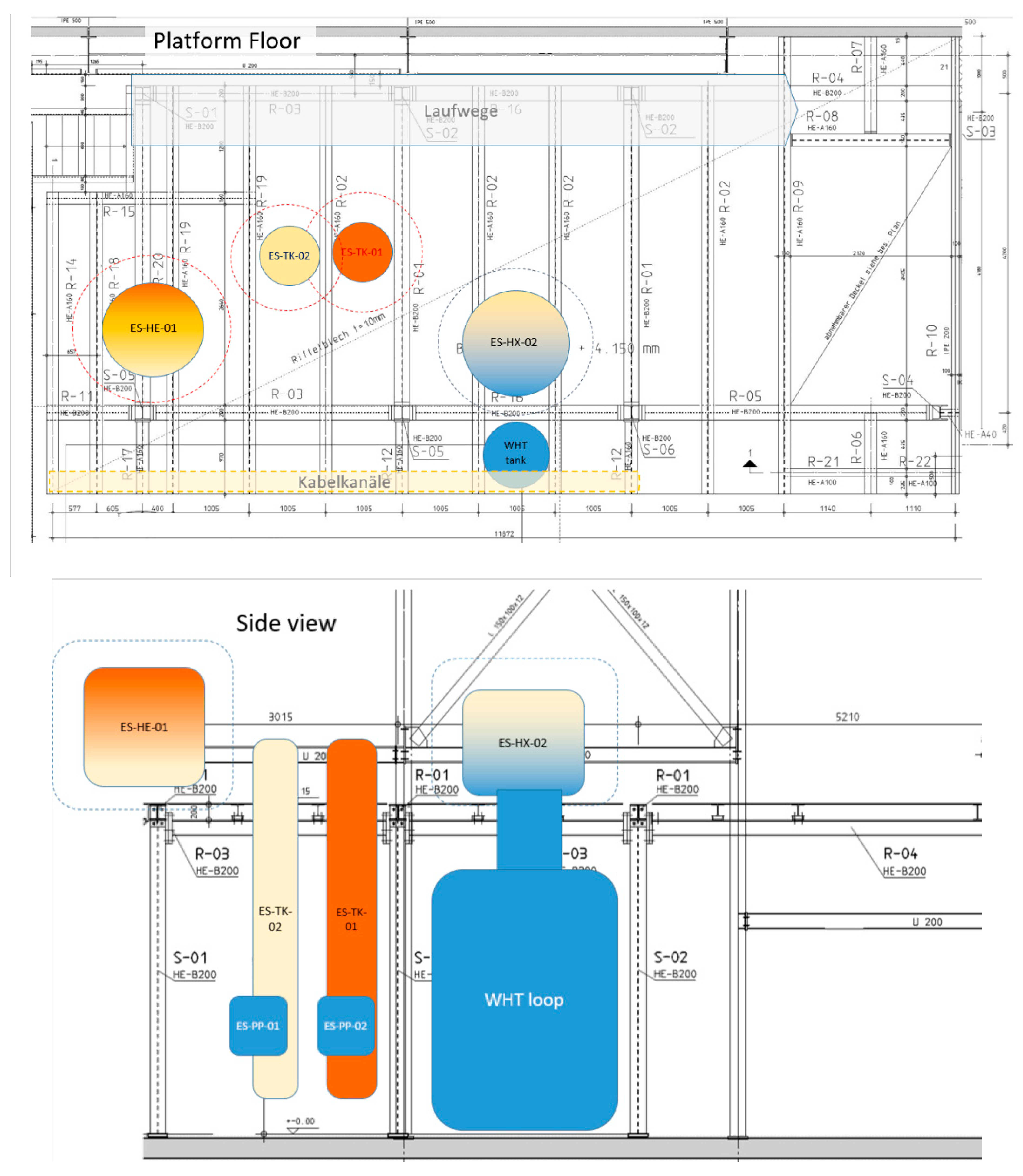
Dimension and Location
The HELOKA-US platform is built at 4 m level to provide space and adequate height for HELOKA-US components. The platform aligns to the exiting HELOKA-HP platform to allow connections to He and cooling water sources. The arrangement of the new components is depicted in
Figure 6. For the latter Phase 1b, the He-MS HX will be located at 8.5 m on the existing HELOKA-HP platform. The allocation of the components considers the connection to the water and helium sources, the KIT operational safety requirements, and maintenance space. The two tanks are in a slim geometry with a height of about 5 m to approach the tank height in DEMO HCPB ESS as closely as possible. The two tanks include additional volume to allow margins of experimental operation and to simulate the heat transfer inertia in the whole DEMO HCPB IHTS piping system.
3.3. Operation Modes
With the loop configuration in HELOKA-US is able to simulate and investigate both conditioning modes and power generation modes conceptualized in DEMO as shown in
Figure 7.
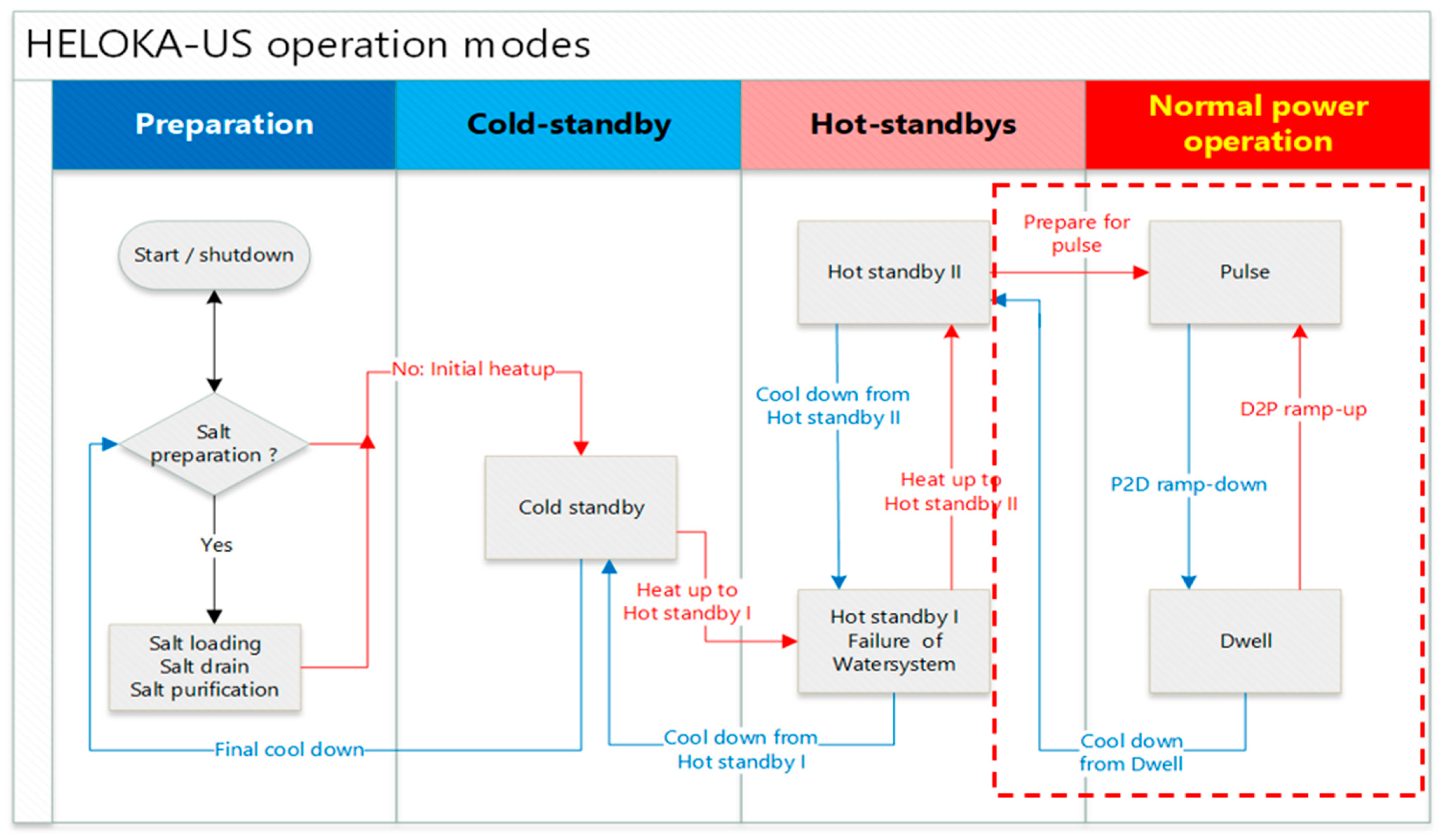
Figure 8 interprets the HELOKA-US preparation/maintenance modes and normal power general modes with the transient routes. The operation modes inside the red frame indicate frequent and fast transitions among the modes. The temperature levels of cold standby and hot standby I are about 200 °C and 270 °C, respectively. In the hot standby II mode, addressing the preparation for the first pulse operation, the MS in tank ES-TK-01 is heated up to 465 °C and the hot leg is heated up to 290 °C.
In
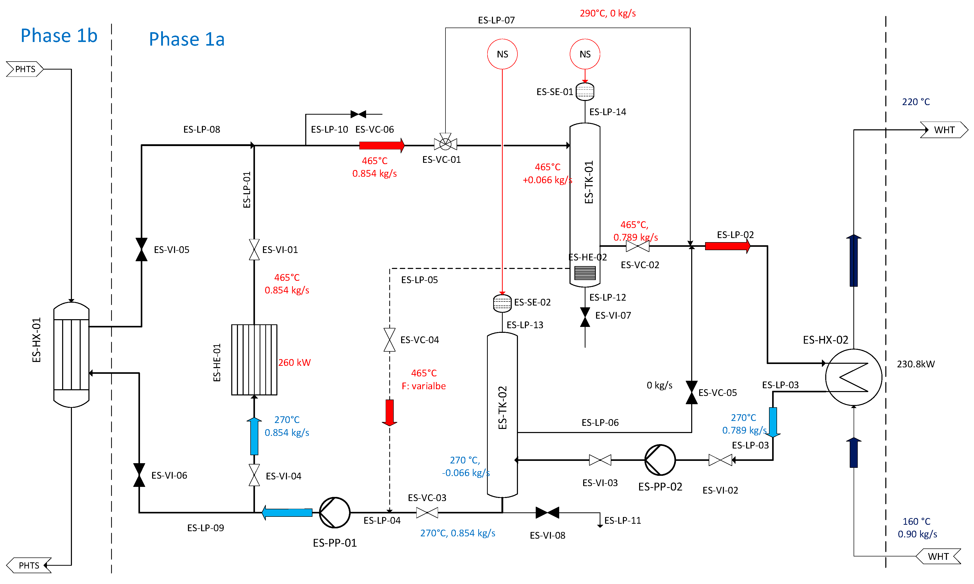
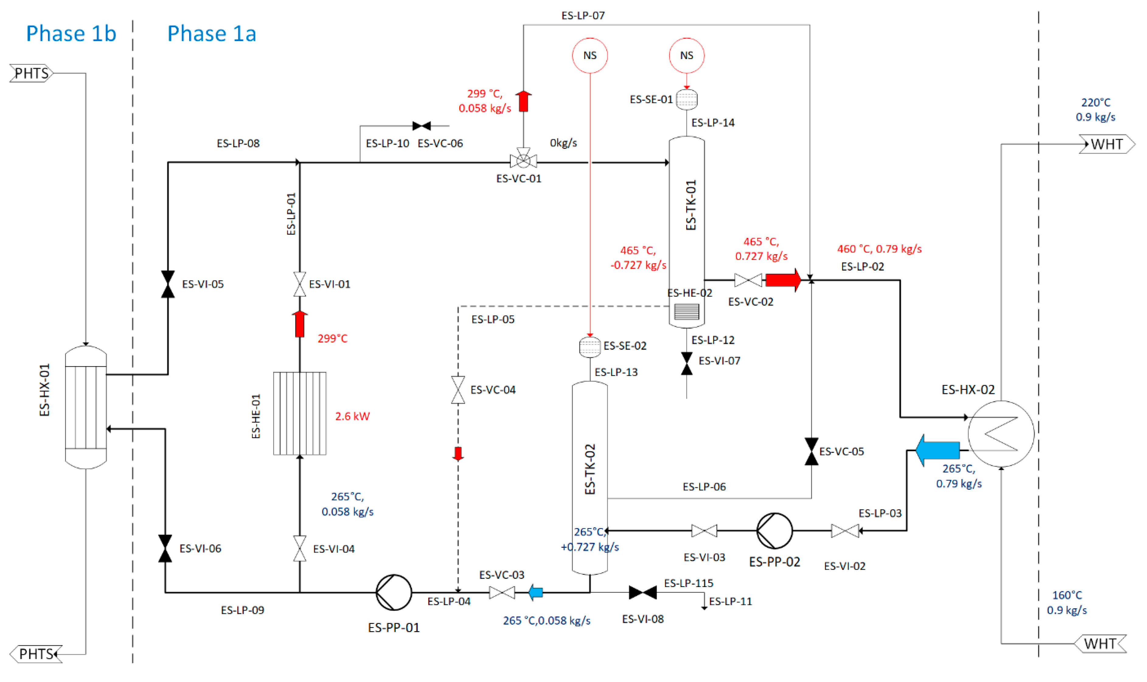
Figure 9 and
Figure 10, the temperature and mass flow of MS in pulse and dwell modes are depicted, respectively. The functions of pulse and dwell modes are briefly described as follows:
Pulse flat top: ES-HE-01 simulates the heat source of the helium with 260 kW. The bypass ES-LP-05 with the valve ES-VC-04 regulates the precise demand on the MS inlet and outlet temperatures in ES-HE-01. Duration: about 7200 s.
Dwell flat bottom: The ES-HE-01 power level is 2.6 kW and it is cooled by a small stream of MS from ES-TK-02. The bypass ES-LP-05 regulates the inlet and outlet MS temperatures through ES-HE-01. MS from the ES-HE-01 is directed to bypass ES-LP-07 and is merged in the upstream of ES-HX-02 so that the MS in ES-TK-01 remains at 465 °C and not below. The duration is 600 s.
4. Simulation Activity
The simulation activity for the DEMO HCPB BoP ICD conceptual design was and is currently being performed using the industrial tool EBSILON [
8,
9]. EBSILON@Professional is a calculation tool for the conceptual design of the power plant performance [
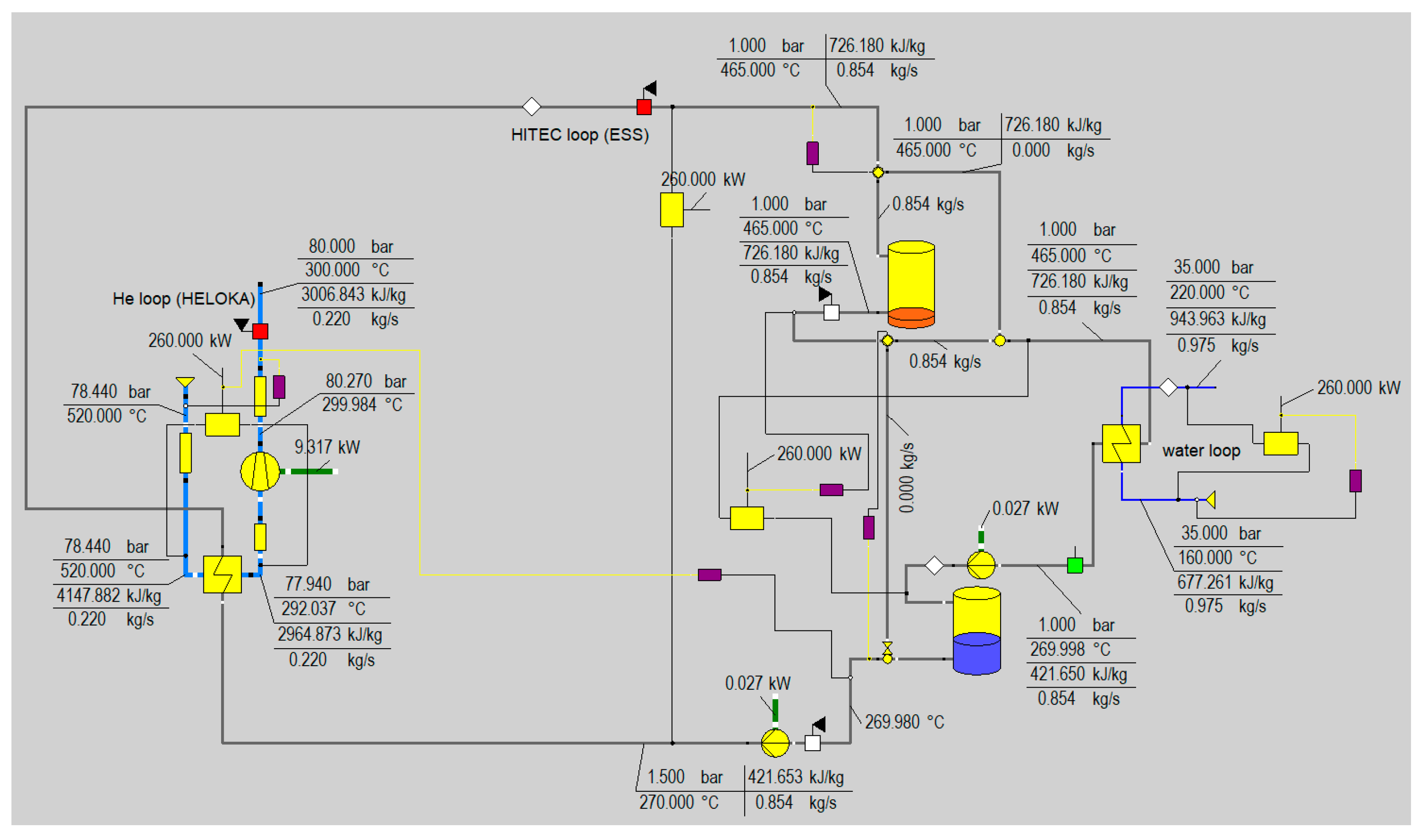
18]. A preliminary simulation of the HELOKA-US MS loop power generation phase was carried out, as shown in
Figure 11. For the dynamic simulation of the transient processes, a model based on the tool MODELICA/DYMOLA is being set up [
19]. The first calculation on the HELOKA-US pulse operation was carried out, and the simulation of the other operational modes will be followed.
5. Conclusions
HELOKA-US, a mockup of the EU-DEMO HCPB BoP ICD with a HITEC molten salt energy storage system, will be under construction at KIT after the conceptual design of the facility has been completed. The new experimental facility will take profit of the available existing helium, water, and data acquisition/control infrastructure from HELOKA-HP. Supported by different simulation tools, the optimized component arrangement and size can represent the DEMO HCPB IHTS-ESS, even if its power and volume scaling is of about 1:1000. Additional volume in the molten salt tanks simulates typical DEMO HCPB BoP ICD peculiarities, such as the long MS pipes in the IHTS.
The designed configuration of the HELOKA-US molten salt loop can not only provide stable power to the PCS throughout pulse and dwell operations, but also realize diverse preparation and maintenance modes. Furthermore, the molten salt loop enables the flexibility and sensibility in regulation and control that reacts to the rapid transients such as pulse-to-dwell and dwell-to-pulse.
The preparation of the experimental hall hosting the facility started in 2021 and ended with the construction of the structural platform by mid-2022 together with the infrastructure extension in KIT Building 660. The erection of the MS loop and all related components and systems as in Phase 1a are planned for 2023. The results of the experimental campaign are planned in early 2024.
Author Contributions
Conceptualization, X.G-L., B.-E.G., E.B. and W.H.; methodology, X.G.-L.; software, E.B.; validation, B.E; writing—original draft preparation: X.G.-L.; writing—review and editing, E.B., W.H., and S.P.-M.; project administration, S.P.-M. All authors have read and agreed to the published version of the manuscript.
Funding
This research was funded by EUROfusion Consortium. EUROFusion is funded by the European Union via the Euratom Research and Training Programme (Grant Agreement No 101052200 EUROfusion). The APC was funded by Karlsruhe Institute of Technology.
Data Availability Statement
The study did not report any data.
Acknowledgments
This research was funded by EUROfusion Consortium. EUROFusion is funded by the European Union via the Euratom Research and Training Programme (Grant Agreement No 101052200 EUROfusion. Views and opinions expressed, however, are those of the author(s) only and do not necessarily reflect those of the European Union or the European Commission. Neither the European Union nor the European Commission can be held responsible for them.
Conflicts of Interest
The authors declare no conflict of interest.
Abbreviations
| BoP | Balance of Plant | IHTS | Intermediate Heat Transfer System. |
| DEMO | DEMOnstration power plant | KIT | Karlsruhe Institute of Technology |
| D2P | Dwell-to-Pulse transient | MS | Molten Salt, HITEC ™ in HELOKA-US |
| ESS | Energy Storage System | P2D | Pulse-to-Dwell transient |
| HCPB | Helium-Cooled Pebble Bed (Blanket) | PCS | Power Conversion System |
| HCPB BOP ICD | HCPB Indirect Coupling Design variant of Balance of Plant | PHTS | Primary Heat Transfer System |
| HE | Helium | | |
| HELOKA | Helium Loop Karlsruhe | | |
| HELOKA-US | HELOKA—Upgrade Storage system | | |
| HELOKA-HP | HELOKA High temperature high pressure Helium Loop | | |
| HITEC | Commercial mark of a nitrite/nitrate molten salt | | |
| HX | Heat Exchanger | | |
| ICD | Indirect Coupling Design | | |
References
- Federici, G.; Bachmann, C.; Biel, W.; Boccaccini, L.; Cismondi, F.; Ciattaglia, S. Overview of the design approach and prioritization of R&D activities towards an EU DEMO. Fusion Eng. Des. 2016, 109–111, 1464–1474. [Google Scholar]
- Federici, G.; Bachmann, C.; Barucca, L.; Biel, W.; Boccaccini, L.; Brown, R.; Bustreo, C.; Ciattaglia, S.; Cismondi, F.; Coleman, M.; et al. DEMO design activity in Europe: Progress and updates. Fusion Eng. Des. 2018, 136, 729–741. [Google Scholar] [CrossRef]
- Barucca, L.; Bubelis, E.; Ciattaglia, S.; D’Alessandro, A.; Nevo, A.D.; Giannetti, F.; Hering, W.; Lorusso, P. Pre-conceptual design of EU DEMO balance of plant systems: Objectives and challenges. Fusion Eng. Des. 2021, 169, 112504. [Google Scholar] [CrossRef]
- Hering, W.; Bubelis, E.; Perez-Martin, S.; Bologa, M.-V. Overview of Thermal Hydraulic Optimization and Verification for the EU-DEMO HCPB BOP ICD Variant. Energies 2021, 14, 7894. [Google Scholar] [CrossRef]
- Barucca, L.; Hering, W.; Perez Martin, S.; Bubelis, E.; Del Nevo, A.; Di Prinzio, M.; Caramello, M.; D’Alessandro, A.; Tarallo, A.; Vallone, E.; et al. Maturation of critical technologies for the DEMO balance of plant systems. Fusion Eng. Des. 2022, 179, 113096. [Google Scholar] [CrossRef]
- Moscato, I.; Barucca, L.; Bubelis, E.; Caruso, G.; Ciattaglia, S.; Ciurluini, C.; Del Nevo, A.; Di Maio, P.A.; Giannetti, F.; Hering, W.; et al. Tokamak cooling systems and power conversion system options. Fusion Eng. Des. 2022, 178, 113093. [Google Scholar] [CrossRef]
- Moscato, I. Progress in the design development of EU DEMO helium-cooled pebble bed primary heat transfer system. Fusion Eng. Des. 2019, 146, 2416–2420. [Google Scholar] [CrossRef]
- Bubelis, E.; Hering, W.; Perez-Martin, S. Conceptual designs of PHTS, ESS and PCS for DEMO BoP with helium cooled BB concept. Fusion Eng. Des. 2018, 136, 367–371. [Google Scholar] [CrossRef]
- Bubelis, E.; Hering, W.; Perez-Martin, S. Industry supported improved design of DEMO BoP for HCPB BB concept with energy storage system. Fusion Eng. Des. 2019, 146, 2334–2337. [Google Scholar] [CrossRef] [Green Version]
- Siccinio, M. Foreseeable transient phases in DEMO (Ramp-up, ramp-down and divertor reattachment). In Proceedings of the 6th IAEA DEMO Workshop, Moscow, Russia, 1–4 October 2019. [Google Scholar]
- Ghidersa, B.E.; Ionescu-Bujor, M.; Janeschitz, G. Helium Loop Karlsruhe (HELOKA): A valuable tool for testing and qualifying ITER components and their He cooling circuits. Fusion Eng. Des. 2006, 81, 1471–1476. [Google Scholar] [CrossRef]
- Ghidersa, B.E.; Jin, X.; Rieth, M.; Ionescu-Bujor, M. KATHELO: A new high heat flux component testing facility. Fusion Eng. Des. 2013, 88, 854–857. [Google Scholar] [CrossRef]
- Gaus-Liu, X.; Cron, T.; Fluhrer, B. Experimental Studies on Two-Layer Corium Heat Transfer in Light Water Reactor Lower Head in LIVE2D Facility. Nucl. Technol. 2020, 206, 1385–1396. [Google Scholar] [CrossRef]
- Gaus-Liu, X.; Miassoedov, A.; Cron, T.; Wenz, T. In-vessel melt pool coolability test—Description and results of live experiments. Nucl. Eng. Des. 2010, 240, 3898–3903. [Google Scholar] [CrossRef]
- Coastal Chemical Co., L.L.C. HITEC Heat Transfer Salt; Coastal Chemical Co., L.L.C.: Plains, KS, USA.
- Fernández, A.G.; Galleguillos, H.; Fuentealba, E.; Pérez, F.J. Thermal characterization of HITEC molten salt for energy storage in solar linear concentrated technology. J. Therm. Anal. Calorim. 2015, 122, 3–9. [Google Scholar] [CrossRef]
- Olivares, R.I. The thermal stablity of molten nitrate/nitrates salt for solar energy storgae in different atmospheres. Sol. Energy 2012, 86, 2576–2583. [Google Scholar] [CrossRef]
- EBSILON@Professional, STEAG Energy Services—System Technologies. Available online: https://www.ebsilon.com/en/ (accessed on 30 November 2022).
- DYMOLA Systems, Dassault Systems. Available online: https://www.3ds.com/de/produkte-und-services/catia/produkte/dymola/ (accessed on 13 May 2022).
| Publisher’s Note: MDPI stays neutral with regard to jurisdictional claims in published maps and institutional affiliations. |
© 2022 by the authors. Licensee MDPI, Basel, Switzerland. This article is an open access article distributed under the terms and conditions of the Creative Commons Attribution (CC BY) license (https://creativecommons.org/licenses/by/4.0/).


 ,
, 


