1. Introduction
For the DEMO reactor, tungsten is considered as an armor material [
1]. Eurofer97 is planned to be used as a structural material for the first wall [
2] and in the divertor region, especially for the shielding liner component [
3]. The steady-state thermal loads on these components are expected to be in the range of 1–2 MW/m
2 [
3,
4]. At present, a tungsten coating (~2 mm) is the envisaged reference technological solution [
2,
3]. The use of massive tungsten could be an advantage as a fully dense armor material. With this configuration, the joining between bulk tungsten and the Eurofer97 material is required. In this regard, some developments are underway (direct joining, copper brazing, W and Eurofer97 functional gradient material (FGM), etc.). An overview of existing solutions is presented in Heuer et al. [
5].
The FGM solution aims at reducing the thermal stresses at the materials’ interface, due to the minimization of the difference in the coefficients of thermal expansion (CTE, α) between the materials.
The present study proposes a joining solution, based on the FGM concept, which, additionally to some of the advantages of the existing materials used as an interlayer between W and Eurofer97, could reduce the long-term activation of the joining material, which is one of the European DEMO’s goals [
6]. Cold spray [
7] and hot isostatic pressing (HIP) processes are envisaged to achieve the manufacturing of FGM and its joining to W and Eurofer97. These technologies have been indeed successfully combined for the manufacturing and the joining of FGM between W and CuCrZr, for the divertor target application [
8]; therefore, they may represent adequate combined solutions to provide good-quality joining between the bulk W and Eurofer97 materials. One of the main advantages of the cold spray process is to produce thick layers (>100 µm) with high density (>94%). The advantage of HIP is to join materials with uniform strength in all directions, preventing the risk of inadequate joining.
This paper presents a preliminary assessment of these technologies as a solution to obtain an FGM and a reliable joining solution between W and Eurofer97. The FGM interlayer is constituted of individual layers. The first part of this paper presents the rationale for the choice of materials as an interlayer between W and Eurofer97. The second part describes the materials and techniques (manufacturing processes and testing methods) used to manufacture the different individual layers and the FGM interlayer. Then, the manufacturing of the complete graded layer constituted of individual layers is described. The quality of the final joining (W, graded layer and Eurofer97) is assessed by checking the cohesion of the interfaces.
2. Choice of Materials Constituting the FGM Interlayer
The interlayer composition is chosen in order to favor a material with reduced activation, manufacturing feasibility using the cold spray process and joining feasibility using diffusion bonding. In terms of activation, the objective is to choose a material for which the residual activation is lower than that of iron. The characteristics of potential materials, with regard to activation, are taken from Gilbert et al. [
9].
To minimize the stress at the interface during tokamak operation, materials with an intermediate CTE between those of W and Eurofer97 could be advantageous as interlayer materials.
As a result, several materials are tested, such as Ta, Ti, Inconel 625, Ta6V and Cu.
For an equivalent surface temperature, in order to maximize the thermal power exhausted by the plasma-facing component, the thermal conductivity of the candidate materials should be maximized. For all candidates, the thermal conductivity is detailed in
Table 1.
Among the candidates, Ti is known to be damaged under exposure to hydrogen (H) plasmas [
10]. However, if the Ti is far enough from H exposure, embrittlement could be avoided.
Considering the binary and ternary phase diagrams, related to the combinations of candidate materials, some intermetallic species could be formed during the manufacturing process. However, as these diagrams consider the equilibrium state, which could not be reached with the considered manufacturing steps, we decided not to take into account the probability of the presence of fragile intermetallic species as a major factor for the choice of the candidate materials. The effect of intermetallic species on the applicability of the FGM interlayer as a joining solution between W and Eurofer97 will be finally assessed in the future via the analysis of the quality of the interface of a mock-up, equipped with the final FGM interlayer configuration, assessed under relevant high-heat-flux testing.
3. Experimental Procedure
3.1. Thermal Spray and Hot Isostatic Pressing
The manufacturing of the individual layers with the thermal spray process and their joining to W and Eurofer97 using HIP were performed in this study. Indeed, these techniques have been used successfully to manufacture a mock-up equipped with a thick FGM layer (500 µm) as an interlayer between W and CuCrZr [
8]. The thermal spray process (cold gas dynamic spray) [
7] is based on the injection and acceleration of particles within a gas stream and presents the advantage of providing high-density materials (>94%) and no metal oxidation during the process [
11]. During impact with the Eurofer97 substrate, particles undergo plastic deformation and adhere to the surface. As in initial investigations for the manufacturing of the individual layer, the Impact Innovation Gmbh (5/11) device was used (pressure up to 5 MPa; maximum temperature of 1100 °C), while, for the manufacturing of graded layers, the Kinetics 3000 (CGT) and 8000 (Oerlikon Metco,) devices were used depending on their availability (maximum pressure 3 or 4 MPa, respectively; maximum temperature of 600 or 1000 °C, respectively). Nitrogen was used as a vector gas during deposition. Process parameters (gas temperature and pressure, spray velocity) were defined in order to obtain a low porosity level after spraying that was compatible with the application (arbitrarily set below 3%). The chemical composition of layers constituted by a combination of materials was arbitrarily set at ±6 vol.%. Porosity, thickness and composition were measured for individually deposited layers by scanning electron microscope (SEM) image analysis.
To favor the HIP’s joining with the FGM, a 30 µm Ni electroplated layer was coated on W [
12]. The W block coated with Ni was then HIPed (1040 °C, 140 Mpa, 2 h) to the Eurofer97 substrate coated with the FGM. As Eurofer97 was heated at a temperature higher than 980 °C (austenitization temperature), a thermal treatment was applied (980 °C for 1 h, followed by thermal quenching and tempering at 750 °C for 5 h).
3.2. Materials
Individual layers, composed of Ta, Ti, Inconel 625, Ta6V and Cu, were manufactured with cold spraying. Powders’ characteristics are given in
Table 2. Reduced-activation ferritic–martensitic steel Eurofer97 was supplied by CEA and its composition is described in [
13]. Eurofer97’s hardness is 221HV30. Tungsten was delivered as tiles of 25 × 25 × 4 mm. The rolling direction was in the 4 mm direction. The microstructure and composition aligned with the tungsten ITER grade requirements [
14].
4. Individual Layer Coating Manufacturing and Assessment of Joining to W and Eurofer97
4.1. Coating
Coating was realised on the Eurofer97 substrate. Temperature and pressure were set to obtain individual layer coatings (300 µm) that were as dense as possible. Unfortunately, the delamination of Ta6V and Cu layers occurred. For these material solutions, W was added to obtain a coating. For Ta, Ti, Inconel 625 and Ta6V + W individual layer depositions, a transverse speed of 200 mm/s, pressure of 4 MPa and temperature of 800 °C were the optimum parameters. For the deposition of Cu + W, the optimum conditions were 200 mm/s, 3.6 MPa, 600 °C. Achieved porosities are listed in
Table 3. They were within the required specification (<3 vol.%), except for that of the Ta6V + W layer.
4.2. Joining
Each individual layer coated onto Eurofer97 was joined by HIP to W. The direct joining of Eurofer97 to tungsten was also performed. After joining, interfaces were observed with optical micrographs. The results of the joining in terms of the presence of cracks at the interface are presented in
Table 4.
As no crack was observed, Ta and Inconel 625 are potential solutions as interlayer materials in contact with Eurofer97. Ti, Cu + W and Ta6V + W are solutions enabling joining with W. Finally, taking into consideration that the highest thermal conductivity of the interlayer material is required, material candidates as graded layers should be composed of Ta and Ti.
5. FGM Interlayer Manufacturing and Assessment of Joining
5.1. Configuration Used for the FGM Interlayer (Composition, Thickness)
Ta (respectively, Ti) was chosen as the layer in contact with Eurofer97 (respectively, W). The chosen configuration did not lead to a linear increase in the thermal dilatation of Eurofer97 and W.
To compensate for the thermal stress in the FGM interlayer induced by the difference in CTE between Ta and Ti, an intermediate layer constituted of a Ta and Ti mixture was implemented between these two materials. For the DEMO divertor, a soft Cu interlayer of 1 mm is used between W and CuCrZr [
3]. Even if this interlayer’s thickness may not be optimal for the joining of W and Eurofer97, the objective of 1 mm FGM thickness between W and Eurofer97 was set in this study. As Ti’s thermal conductivity is poor, the Ti thickness remained as low as possible (100 µm ± 50 µm). This value was driven by the lowest thickness achievable by the cold spray technique.
On the contrary, Ta’s thickness can reach the maximum, since the thermal conductivity is the highest among the materials planned to constitute the interlayer material. The intermediate layer thickness is defined within the range of the mean thickness values between the Ta and Ti layers.
Additionally, the choice of the intermediate layer’s chemical composition is driven by the mechanical strength of the complete FGM interlayer. Tensile tests were performed according to the ASTM C633 standard. Samples dedicated to the tensile tests were constituted by the assembly of W, an individual layer and Eurofer97. Three intermediate layer chemical compositions were tested: Ta content of 25 vol.% + Ti content of 75 vol.% (25 vol.% Ta + 75 vol.% Ti); 50 vol.% Ta + 50 vol.% Ti; 75 vol.% Ta + 25 vol.% Ti, respectively. In the following, the nomenclature for the chemical composition is reduced to the Ta content, e.g., 25 vol.% Ta for a layer composed of 25 vol.% Ta + 75 vol.% Ti. Coating manufacturing conditions are provided in
Table 5. For the different tested configurations, observations after the mechanical tests showed a rupture at the Ta–Eurofer97 interface. Interface decohesion was obtained at around 15 ± 5 MPa for all tested configurations. Considering the thermal expansion of the intermediate layer, the 50 vol.% Ta solution appears to provide a good balance as a layer between Ta and Ti.
5.2. Graded Material Manufacturing and Joining
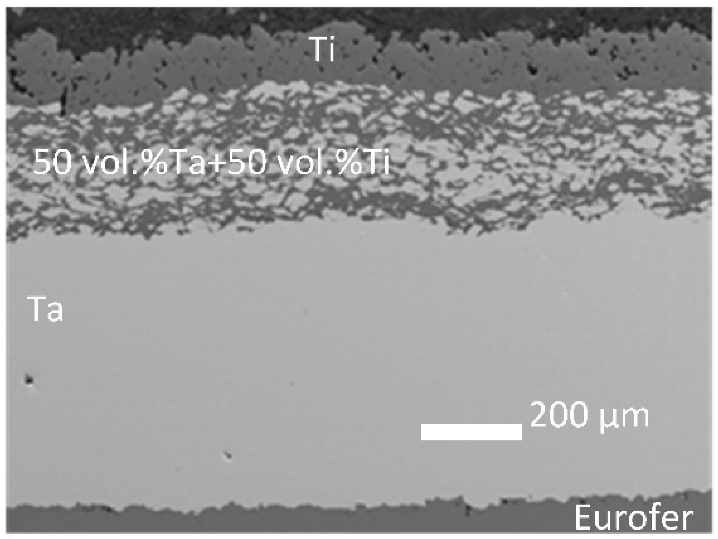
Before coating, substrate surface cleaning and polishing were applied. The manufactured FGM interlayer is presented in
Figure 1. The measured chemical compositions were within the specifications (±5 vol.%). Coating conditions and characteristics (thickness, porosity) are presented in
Table 5. Porosity is emphasized by the presence of black spots on the SEM images, at the Ta–Eurofer97 interface and within the Ti layer (
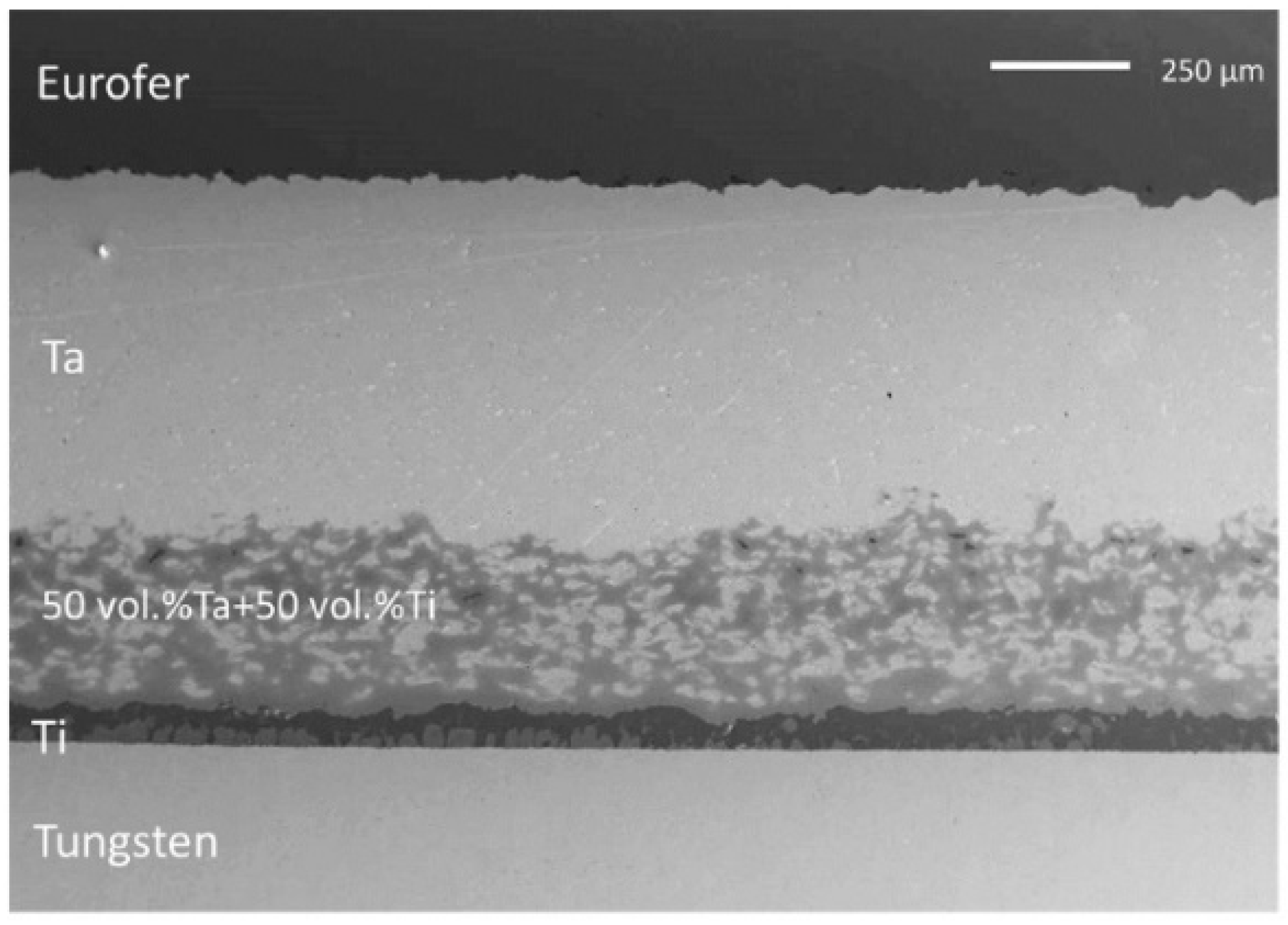
Figure 1). The porosity was reduced after the HIP process (
Figure 2). After HIP joining, no crack is visible at the interfaces (
Figure 2). Eurofer97’s hardness measured after the complete manufacturing process is 296HV30, which is higher than the hardness corresponding to its raw state.
The chemical composition of the complete joining was analyzed with energy-dispersive X-ray (EDX), using the INCA X-ACT system, on particular zones; a qualitative analysis of the chemical elements present was then performed (
Table 6). One should note that this study did not aim to define exactly the species formed and induced by the thermal diffusion and the reaction of the different chemical elements. The presence of Al and Si isnoticed, which is possibly due to impurities induced by the cold spray process. No Ta is present in Eurofer97. Ta, mixed with Cr, W and Fe, is present at the interface between Eurofer97 and Ta. Fe is noticed within the Ta layer. Based on the binary diagrams, the presence of intermetallic species is expected. The possible detrimental effect of these intermetallic species will be assessed by the high-heat-flux testing of the mock-up manufactured with the developed complete joining.
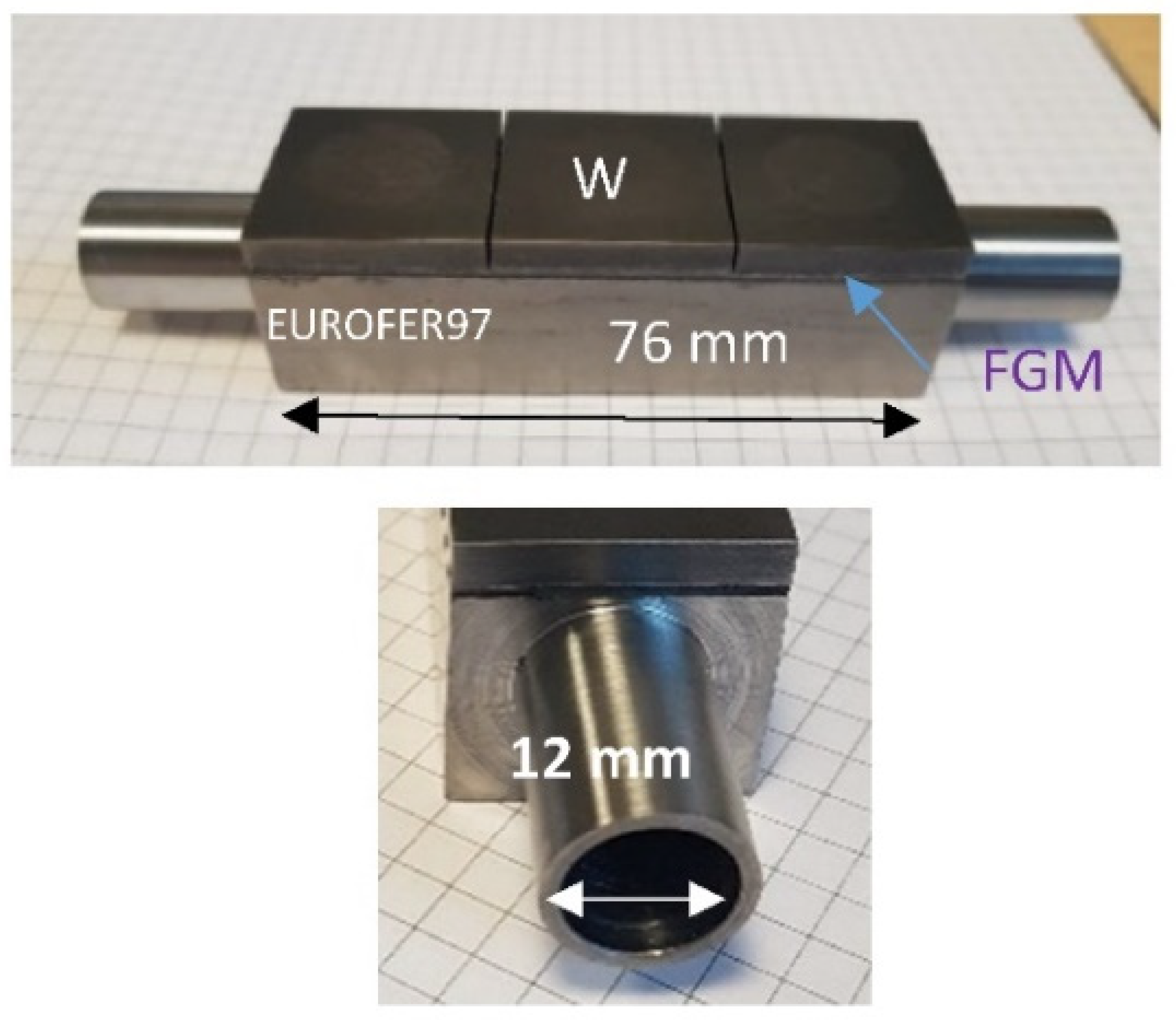
A complete mock-up was then manufactured using the same processes and conditions as the ones used for the manufacturing of the studied samples (
Figure 3). The analysis of the interface via non-destructive techniques and heat flux testing is planned for the near future.
6. Conclusions
For the future DEMO reactor, tungsten is being considered as the material facing the plasma. Eurofer97 is planned to be used as a structural material for the first wall component and in the divertor region (shielding liner component). Several joining solutions between W and Eurofer97 have been studied. In the present study, the choice of the joining material was driven, among other constraints, by the desire to minimize the thermal stresses at the materials’ interfaces. In this regard, FGM represents a promising solution. Another constraint concerns the manufacturing process involved, which should be an improved industrial process. The present study proposed a joining solution, based on Ti and Ta FGM, which, additionally to the advantages of the existing solutions, could reduce the long-term activation of the joining material. In this study, we showed that, due to the achieved density (>94%) and to the composition’s accuracy (±6 vol.%), the cold spray process could be adapted to the fabrication of the Ti/Ta FGM. The final joining between W, FGM and Eurofer97 was achieved using hot isostatic pressing, followed by a thermal treatment to recover Eurofer97’s mechanical properties. After FGM manufacturing on the Eurofer97 substrate and HIP joining to W, no crack was present at the interfaces. Multi-phase species were emphasized, especially within the Ti layer. The applicability of the developed joining solution will be further assessed with an appropriate mock-up subjected to high-heat-flux testing and hydrogen plasma loading. Once the performance is assessed and the final desired component geometry is defined, the optimization of the FGM interlayer thickness by finite element modeling could be carried out.
Author Contributions
Conceptualization, M.R. (Marianne Richou); Methodology, M.R. (Marianne Richou) and E.M.; Investigation, all authors; Writing, M.R. (Marianne Richou); Review, all authors. All authors have read and agreed to the published version of the manuscript.
Funding
We acknowledge the financial support of the Cross-Disciplinary Program on Materials of CEA, the French Alternative Energies and Atomic Energy Commission.
Data Availability Statement
Not applicable.
Acknowledgments
We acknowledge Jean Henry from CEA for providing Eurofer97. ICB is supported by the EUR-EIPHI Graduate School (Grant No. 17-EURE-0002).
Conflicts of Interest
The authors declare no conflict of interest.
References
- Pintsuk, G.; Aiello, G.; Dudarev, S.L.; Gorley, M.; Henry, J.; Richou, M.; Rieth, M.; Terentyev, D.; Vila, R. Materials for in-vessel components. Fusion Eng. Des. 2022, 174, 112994. [Google Scholar] [CrossRef]
- Forest, L.; Aktaa, J.; Boccaccini, L.V.; Emmerich, T.; Eugen-Ghidersa, B.; Fondant, G.; Froio, A.; Puma, A.L.; Namburi, H.; Neuberger, H.; et al. Status of the EU DEMO breeding blanket manufacturing R&D activities. Fusion Eng. Des. 2020, 152, 111420. [Google Scholar] [CrossRef]
- You, J.; Mazzone, G.; Visca, E.; Greuner, H.; Fursdon, M.; Addab, Y.; Bachmann, C.; Barrett, T.; Bonavolontà, U.; Böswirth, B.; et al. Divertor of the European DEMO: Engineering and technologies for power exhaust. Fusion Eng. Des. 2022, 175, 113010. [Google Scholar] [CrossRef]
- Maviglia, F.; Bachmann, C.; Federici, G.; Franke, T.; Siccinio, M.; Albanese, R.; Ambrosino, R.; Arter, W.; Bonifetto, R.; Calabrò, G.; et al. Integrated design strategy for EU-DEMO first wall protection from plasma transients. Fusion Eng. Des. 2022, 177, 113067. [Google Scholar] [CrossRef]
- Heuer, S.; Coenen, J.W.; Pintsuk, G.; Matějíček, J.; Vilémová, M.; Linsmeier, C. Overview of challenges and developments in joining tungsten and steel for future fusion reactors. Phys. Scr. 2020, T171, 014028. [Google Scholar] [CrossRef]
- Federici, G.; Holden, J.; Baylard, C.; Beaumont, A. The EU DEMO staged design approach in the Pre-Concept Design Phase. Fusion Eng. Des. 2021, 173, 112959. [Google Scholar] [CrossRef]
- Sova, A.; Grigoriev, S.; Okunkova, A.; Smurov, I. Potential of cold gas dynamic spray as additive manufacturing technology. Int. J. Adv. Manuf. Technol. 2013, 69, 2269–2278. [Google Scholar] [CrossRef]
- Richou, M.; Gallay, F.; Böswirth, B.; Chu, I.; Dose, G.; Greuner, H.; Kermouche, G.; Lenci, M.; Loewenhoff, T.; Maestracci, R.; et al. Performance assessment of thick W/Cu graded interlayer for DEMO divertor target. Fusion Eng. Des. 2020, 157, 111610. [Google Scholar] [CrossRef]
- Gilbert, R.; Mark; Sublet, J.C.; Forrest, R.A. Handbook of Activation, Transmutation, and Radiation Damage Properties of the Elements Simulayted Using FISPACT-II and TENDL-2014: Magnetic Fusion Plant. 2015. Available online: https://doi.org/10.13140/RG.2.2.16703.92323 (accessed on 12 December 2021).
- Wójcik-Gargula, A.; Rubel, M.; Batistoni, P.; Bekris, N.; Colling, B.; Dutkiewicz, E.; Laas, T.; Nobs, C.; Paju, J.; Packer, L.; et al. Studies on the behaviour of titanium activation foils during long-term exposure at the JET tokamak. Fusion Eng. Des. 2022, 177, 113056. [Google Scholar] [CrossRef]
- Stoltenhoff, T.; Kreye, H.; Richter, H.J. An analysis of the cold spray process and its coatings. J. Therm. Spray Technol. 2002, 11, 542–550. [Google Scholar] [CrossRef]
- Rigal, E.; Bucci, P.; Le Marois, G. Fabrication of monoblock high heat flux components for ITER divertor upper vertical target using hot isostatic pressing diffusion welding. Fusion Eng. Des. 2000, 49–50, 317–322. [Google Scholar] [CrossRef]
- Hoffmann, J.; Rieth, M.; Klimenkov, M.; Baumgärtner, S. Improvement of EUROFER’s mechanical properties by optimized chemical compositions and thermo-mechanical treatments. Nucl. Mater. Energy 2018, 16, 88–94. [Google Scholar] [CrossRef]
- Hirai, T.; Barabash, V.; Escourbiac, F.; Durocher, A.; Ferrand, L.; Komarov, V.; Merola, M. ITER divertor materials and manufacturing challenges. Fusion Eng. Des. 2017, 125, 250–255. [Google Scholar] [CrossRef]
| Publisher’s Note: MDPI stays neutral with regard to jurisdictional claims in published maps and institutional affiliations. |
© 2022 by the authors. Licensee MDPI, Basel, Switzerland. This article is an open access article distributed under the terms and conditions of the Creative Commons Attribution (CC BY) license (https://creativecommons.org/licenses/by/4.0/).


