

Thermomechanical Analysis of a PFC Integrating W Lattice Armour in Response to Different Plasma Scenarios Predicted in the EU-DEMO Tokamak
 , , , ,
Abstract
:1. Introduction
2. 2D Parametric Optimisation Analysis
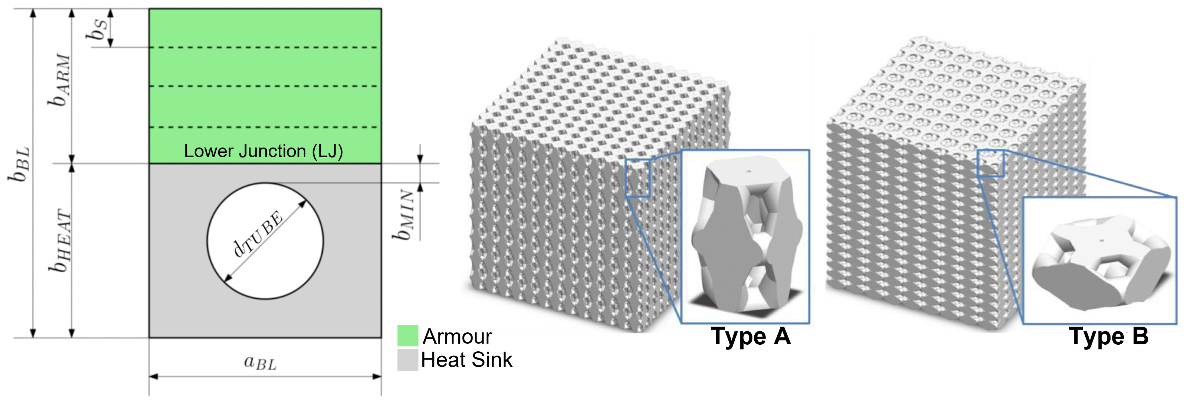
- , fraction of the total height of the component, occupied by armour:
- mm, pitch between adjacent channels
- mm, minimal thickness of the heat sink, i.e., the minimal distance between the cooling water and the lower kunction (LJ)
- sez ∈ [circular, square], shape of cooling pipe section (circular with a diameter equal to , square mm)
- inter ∈ [brazing, infiltration], LJ type;
- mm, pipe diameter;
- Type ∈ [Type A, Type B], elementary cell morphology;
- [CuCrZr, P91, EUROFER97], heat sink material;
- , armour stratification.

- Absence of melting phenomena in the lower half of the armour.
- Absence of melting phenomena everywhere in the heat sink.
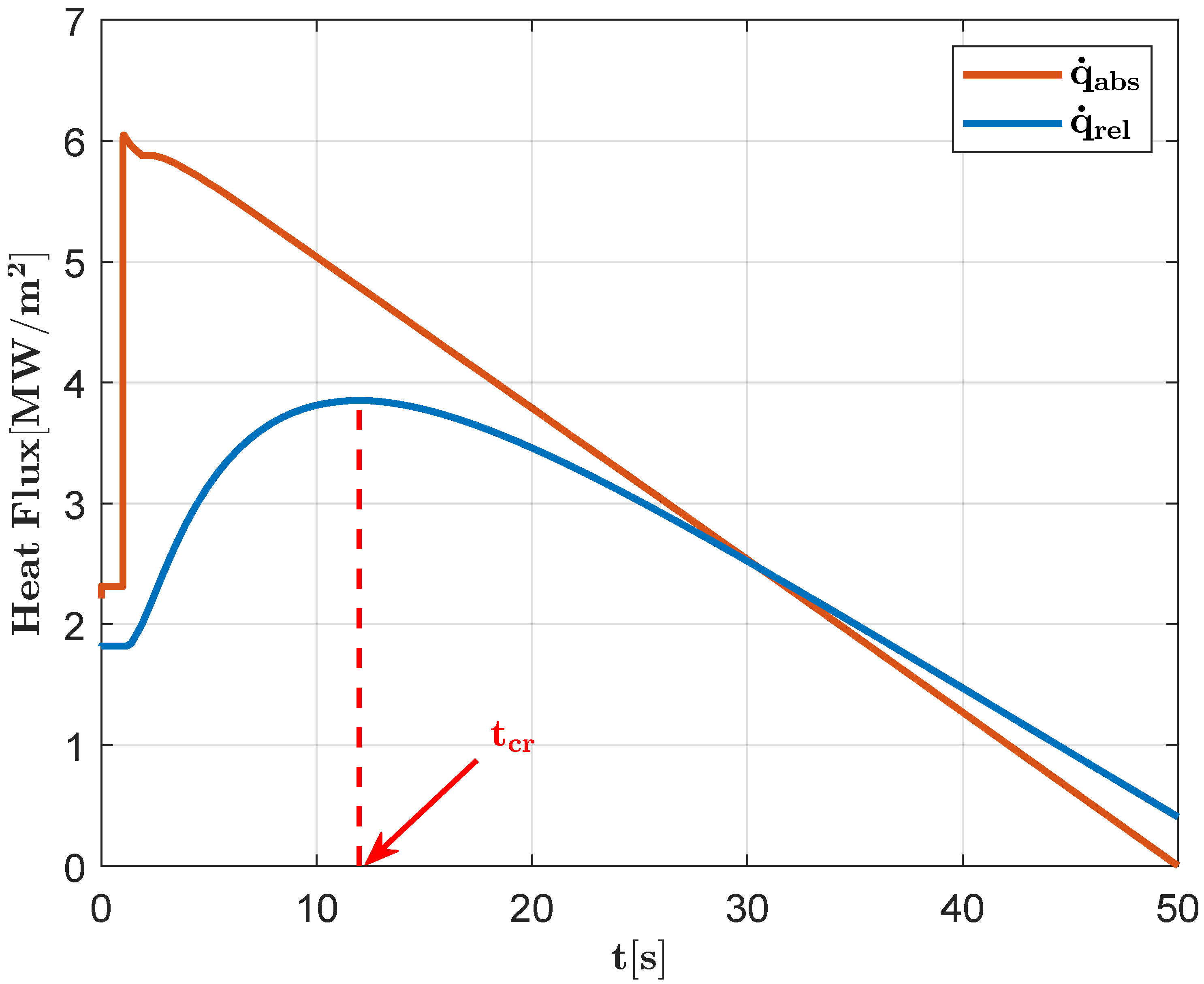
- The absence of melting phenomena in all layers of the armour. Unlike the disruption, the ramp down is an operating condition foreseen with the nominal operation of the reactor. During the ramp-down phase, therefore, any possibility of the degradation of the sacrificial component must be avoided.
- Cooling pipe wall temperature of less than K to ensure a safety margin from the critical heat flux (CHF) according to the Tong-75 correlation [15]. In the case of disruption, this condition was not applied due to the extremely short duration of the transient.
- Adequate structural performance of the heat sink. Compliance with this condition requires that the maximal temperature of the heat sink never exceed 573 K in the case of heat sink produced with a CuCrZr alloy, and 823 K if it consists of EUROFER97 or P91 steel [16].
3. Thermostructural Assessment of the Component
3.1. SDC-IC Standards
- is the primary membrane stress;
- is the primary bending stress;
- is the local membrane stress;
- is the secondary local membrane stress;
- is the maximal steady stress intensity value of the sum of the primary membrane and bending stress reached during the cycle;
- is the maximal range of the cyclic primary and secondary stress intensities;
- and are the allowable stresses;
- is a geometry and neutron-dose-dependant factor.

| HS | Immediate plastic collapse and plastic instability | |
| Nonductile damage modes | ||
| HS ARM | Ratcheting (low temperature) |
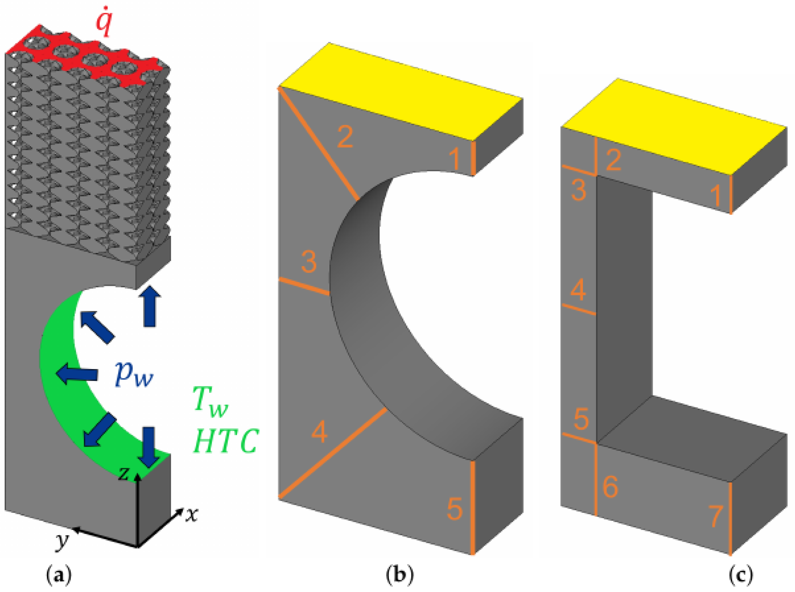
3.2. 3D Model
4. Results and Discussion
5. Conclusions
Author Contributions
Funding
Conflicts of Interest
References
- Donné, A.J. The European roadmap towards fusion electricity. Phil. Trans. R. Soc. A 2019, 377, 20170432. [Google Scholar] [CrossRef] [PubMed] [Green Version]
- Barrett, T.R.; Ellwood, G.; Pérez, G.; Kovari, M.; Fursdon, M.; Domptail, F.; Kirk, S.; Mcintosh, S.C.; Roberts, S.; Zheng, S.; et al. Progress in the engineering design and assessment of the European DEMO first wall and divertor plasma facing components. Fusion Eng. Des. 2016, 109, 917–924. [Google Scholar] [CrossRef] [Green Version]
- You, J.H. A review on two previous divertor target concepts for DEMO: Mutual impact between structural design requirements and materials performance. Nucl. Fusion 2015, 55, 113026. [Google Scholar] [CrossRef] [Green Version]
- Pintsuk, G.; Aiello, G.; Dudarev, S.L.; Gorley, M.; Henry, J.; Richou, M.; Rieth, M.; Terentyev, D.; Vila, R. Materials for in-vessel components. Fusion Eng. Des. 2022, 174, 112994. [Google Scholar] [CrossRef]
- Pintsuk, G. Tungsten as a Plasma-Facing Material. Compr. Nucl. Mater. 2012, 4, 551–581. [Google Scholar] [CrossRef]
- Maviglia, F.; Albanese, R.; Ambrosino, R.; Arter, W.; Bachmann, C.; Barrett, T.; Federici, G.; Firdaous, M.; Gerardin, J.; Kovari, M.; et al. Wall protection strategies for DEMO plasma transients. Fusion Eng. Des. 2018, 136, 410–414. [Google Scholar] [CrossRef]
- Maviglia, F.; Bachmann, C.; Federici, G.; Franke, T.; Siccinio, M.; Albanese, R.; Ambrosino, R.; Arter, W.; Bonifetto, R.; Calabrò, G.; et al. Erratum: Integrated design strategy for EU-DEMO first wall protection from plasma transients (Fusion Engineering and Design (2022) 177, (113067) (S0920379622000679), (10.1016/j.fusengdes.2022.113067)). Fusion Eng. Des. 2022, 178, 113125. [Google Scholar] [CrossRef]
- De Luca, R.; Fanelli, P.; Mingozzi, S.; Calabrò, G.; Vivio, F.; Maviglia, F.; You, J.H. Parametric design study of a substrate material for a DEMO sacrificial limiter. Fusion Eng. Des. 2020, 158, 111721. [Google Scholar] [CrossRef]
- Pestchanyi, S.; Pitts, R.; Lehnen, M. Simulation of divertor targets shielding during transients in ITER. Fusion Eng. Des. 2016, 109–111, 141–145. [Google Scholar] [CrossRef] [Green Version]
- Müller, A.V.; Schlick, G.; Neu, R.; Anstätt, C.; Klimkait, T.; Lee, J.; Pascher, B.; Schmitt, M.; Seidel, C. Additive manufacturing of pure tungsten by means of selective laser beam melting with substrate preheating temperatures up to 1000 °C. Nucl. Mater. Energy 2019, 19, 184–188. [Google Scholar] [CrossRef]
- Srivatsan, T.; Sudarshan, T. Additive Manufacturing: Innovations, Advances, and Applications, 1st ed.; CRC Press: Boca Raton, FL, USA, 2016. [Google Scholar]
- You, J.H.; Bachmann, C.; Belardi, V.G.; Binder, M.; Bowden, D.; Calabrò, G.; Fanelli, P.; Fursdon, M.; Garkusha, I.E.; Gerashchenko, S.; et al. Limiters for DEMO wall protection: Initial design concepts & technology options. Fusion Eng. Des. 2022, 174, 112988. [Google Scholar] [CrossRef]
- Luca, R.D.; Fanelli, P.; Paoletti, D.; Stefanini, C.; Müller, A.V.; Feichtmayer, A.; Vivio, F.; Dose, G.; Sano, G.D.; Roccella, S.; et al. Pre-conceptual design of a PFC provided with a W lattice armour for first wall limiters in the EU-DEMO fusion reactor. In Proceedings of the 32nd Symposium on Fusion Technology (SOFT 2022), Dubrovnik, Croatia, 18–23 September 2022. [Google Scholar]
- Stefanini, C.; Fanelli, P.; De Luca, R.; Paoletti, D.; Vivio, F.; Belardi, V.; Trupiano, S.; You, J.H.; Neu, R.; Calabrò, G. Parametric FE model for the thermal optimization of a Plasma Facing Component equipped with sacrificial lattice armors for First Wall limiter application in EU-DEMO fusion reactor. In Proceedings of the 32nd Symposium on Fusion Technology (SOFT 2022), Dubrovnik, Croatia, 18–23 September 2022. [Google Scholar]
- Raffray, A.R.; Schlosser, J.; Akiba, M.; Araki, M.; Chiocchio, S.; Driemeyer, D.; Escourbiac, F.; Grigoriev, S.; Merola, M.; Tivey, R.; et al. Critical heat flux analysis and R&D for the design of the ITER divertor. Fusion Eng. Des. 1999, 45, 377–407. [Google Scholar] [CrossRef]
- Stork, D.; Agostini, P.; Boutard, J.L.; Buckthorpe, D.; Diegele, E.; Dudarev, S.L.; English, C.; Federici, G.; Gilbert, M.R.; Gonzalez, S.; et al. Developing structural, high-heat flux and plasma facing materials for a near-term DEMO fusion power plant: The EU assessment. J. Nucl. Mater. 2014, 455, 277–291. [Google Scholar] [CrossRef] [Green Version]
- Barabash, V. Structural Design Criteria for ITER In-vessel Components (SDC-IC). ITER-D-222RHC. Version in ITER IDM. 2012. [Google Scholar]
- Aiello, G.; Aktaa, J.; Cismondi, F.; Rampal, G.; Salavy, J.F.; Tavassoli, F. Assessment of design limits and criteria requirements for Eurofer structures in TBM components. J. Nucl. Mater. 2011, 414, 53–68. [Google Scholar] [CrossRef]
- Maviglia, F.; Siccinio, M.; Bachmann, C.; Biel, W.; Cavedon, M.; Fable, E.; Federici, G.; Firdaouss, M.; Gerardin, J.; Hauer, V.; et al. Impact of plasma-wall interaction and exhaust on the EU-DEMO design. Nucl. Mater. Energy 2021, 26, 100897. [Google Scholar] [CrossRef]
- Chiovaro, P.; Mazzone, G.; Di Maio, P.A.; Castrovinci, F.; Quartararo, A.; Vallone, E. DIV-DEMO.S.1-T011-D002. IDM Report. 2022. [Google Scholar]
- You, J.H.; Visca, E.; Barrett, T.; Böswirth, B.; Crescenzi, F.; Domptail, F.; Fursdon, M.; Gallay, F.; Ghidersa, B.E.; Greuner, H.; et al. European divertor target concepts for DEMO: Design rationales and high heat flux performance. Nucl. Mater. Energy 2018, 16, 1–11. [Google Scholar] [CrossRef]
- De Luca, R. Basic characterization of tungsten produced by means of Laser Beam Melting. Master Thesis, University of Rome Tor Vergata, Rome, Italy, 2017. [Google Scholar]
- Vivio, F.; Belardi, V.G.; Paoletti, D.; Villani, G. DIV-DEMO.S.3-T001-D002. IDM Report. 2022.
- I.T.E.R. Organization. Historical Baseline Document: Appendix A Materials Design Limit Data Approved Version. 2013. [Google Scholar]
- Mantel, N.; Bowden, D.; Herashchenko, S.S.; Fursdon, M.; Hancock, A.D.L.; Garkusha, I.E.; Roberts, J.; Makhlai, V.A.; Müller, A.V.; Barrett, T.R.; et al. Corrigendum: Development and testing of an additively manufactured lattice for DEMO limiters (2022 Nucl. Fusion 62 036017). Nucl. Fusion 2022, 62, 129501. [Google Scholar] [CrossRef]


| Type A | Type B | |
|---|---|---|
| Anisotropy 1 | 1.6 | 0.5 |
| Ligament length (mm) | 0.2 | 0.2 |
| Ligament radius (mm) | 0.09 | 0.09 |
| Relative density 2 (%) | 49.6 | 53.1 |
| Relative conductivity 2 (%) | 36.94 | 28.27 |
| Scaling factor | 0.278 | 0.278 |
| Configuration | 1 | 2 |
|---|---|---|
| (mm) | 10.8 | 14.4 |
| (mm) | 17.5 | 10 |
| (mm) | 17 | 10 |
| (mm) | 1.5 | 1 |
| Circular mm | Square mm | |
| Type B | Type A | |
| Brazing | Brazing | |
| CuCrZr | EUROFER | |
| Path | Normal Operation | Ramp Down | ||||||||||||||
|---|---|---|---|---|---|---|---|---|---|---|---|---|---|---|---|---|
| [K] | [MPa] | [MPa] | [K] | [MPa] | [MPa] | |||||||||||
| Configuration 1 | ARM | A | 1185 | 236 | - | - | - | - | 0.786 | 2176 | <160 | - | - | - | - | >3 |
| B | 463 | 462 | - | - | - | - | 0.363 | 517 | 444 | - | - | - | - | 0.674 | ||
| HS | 1 | 447 | 86 | 97 | 0.117 | 0.153 | 0.575 | 0.580 | 474.6 | 86 | 97 | 0.117 | 0.153 | 0.834 | 0.439 | |
| 2 | 447 | 86 | 97 | 0.058 | 0.121 | 0.603 | 0.410 | 473.7 | 86 | 97 | 0.058 | 0.121 | 0.159 | 0.283 | ||
| 3 | 428 | 86 | 97 | 0.141 | 0.172 | 0.141 | 0.126 | 433.1 | 86 | 97 | 0.141 | 0.172 | 0.950 | 0.430 | ||
| 4 | 424 | 86 | 97 | 0.048 | 0.099 | 0.035 | 0.063 | 425 | 86 | 97 | 0.048 | 0.099 | 1.847 | 1.080 | ||
| 5 | 424 | 86 | 97 | 0.103 | 0.123 | 0.072 | 0.076 | 424.1 | 86 | 97 | 0.103 | 0.123 | 1.983 | 1.065 | ||
| Configuration 2 | ARM | A | 1053 | 264 | - | - | - | - | 0.931 | 2001 | <160 | - | - | - | - | >3 |
| B | 502 | 444 | - | - | - | - | 0.305 | 592 | 392 | - | - | - | - | 0.600 | ||
| HS | 1 | 469 | 206 | 195 | 0.028 | 0.038 | 0.226 | 0.128 | 521 | 206 | 195 | 0.028 | 0.038 | 0.481 | 0.341 | |
| 2 | 469 | 206 | 195 | 0.074 | 0.086 | 0.454 | 0.236 | 529 | 206 | 195 | 0.074 | 0.086 | 0.322 | 0.367 | ||
| 3 | 473 | 206 | 195 | 0.060 | 0.085 | 0.154 | 0.091 | 488 | 206 | 195 | 0.060 | 0.085 | 0.820 | 0.416 | ||
| 4 | 454 | 206 | 195 | 0.084 | 0.056 | 0.299 | 0.095 | 424 | 206 | 195 | 0.084 | 0.056 | 1.331 | 0.421 | ||
| 5 | 423 | 206 | 195 | 0.052 | 0.064 | 0.383 | 0.187 | 423 | 206 | 195 | 0.052 | 0.064 | 1.801 | 0.814 | ||
| 6 | 423 | 206 | 195 | 0.038 | 0.050 | 0.459 | 0.182 | 423 | 206 | 195 | 0.038 | 0.050 | 2.114 | 0.793 | ||
| 7 | 423 | 206 | 195 | 0.039 | 0.028 | 0.542 | 0.172 | 423 | 206 | 195 | 0.039 | 0.028 | 2.290 | 0.724 | ||
Publisher’s Note: MDPI stays neutral with regard to jurisdictional claims in published maps and institutional affiliations. |
© 2022 by the authors. Licensee MDPI, Basel, Switzerland. This article is an open access article distributed under the terms and conditions of the Creative Commons Attribution (CC BY) license (https://creativecommons.org/licenses/by/4.0/).
Share and Cite
Paoletti, D.; Fanelli, P.; De Luca, R.; Stefanini, C.; Vivio, F.; Belardi, V.G.; Trupiano, S.; Calabrò, G.; You, J.-H.; Neu, R. Thermomechanical Analysis of a PFC Integrating W Lattice Armour in Response to Different Plasma Scenarios Predicted in the EU-DEMO Tokamak. J. Nucl. Eng. 2022, 3, 421-434. https://doi.org/10.3390/jne3040028
Paoletti D, Fanelli P, De Luca R, Stefanini C, Vivio F, Belardi VG, Trupiano S, Calabrò G, You J-H, Neu R. Thermomechanical Analysis of a PFC Integrating W Lattice Armour in Response to Different Plasma Scenarios Predicted in the EU-DEMO Tokamak. Journal of Nuclear Engineering. 2022; 3(4):421-434. https://doi.org/10.3390/jne3040028
Chicago/Turabian StylePaoletti, Damiano, Pierluigi Fanelli, Riccardo De Luca, Chiara Stefanini, Francesco Vivio, Valerio Gioachino Belardi, Simone Trupiano, Giuseppe Calabrò, Jeong-Ha You, and Rudolf Neu. 2022. "Thermomechanical Analysis of a PFC Integrating W Lattice Armour in Response to Different Plasma Scenarios Predicted in the EU-DEMO Tokamak" Journal of Nuclear Engineering 3, no. 4: 421-434. https://doi.org/10.3390/jne3040028