
Proton-Conducting Ceramic Membranes for the Production of Hydrogen via Decarbonized Heat: Overview and Prospects


Abstract
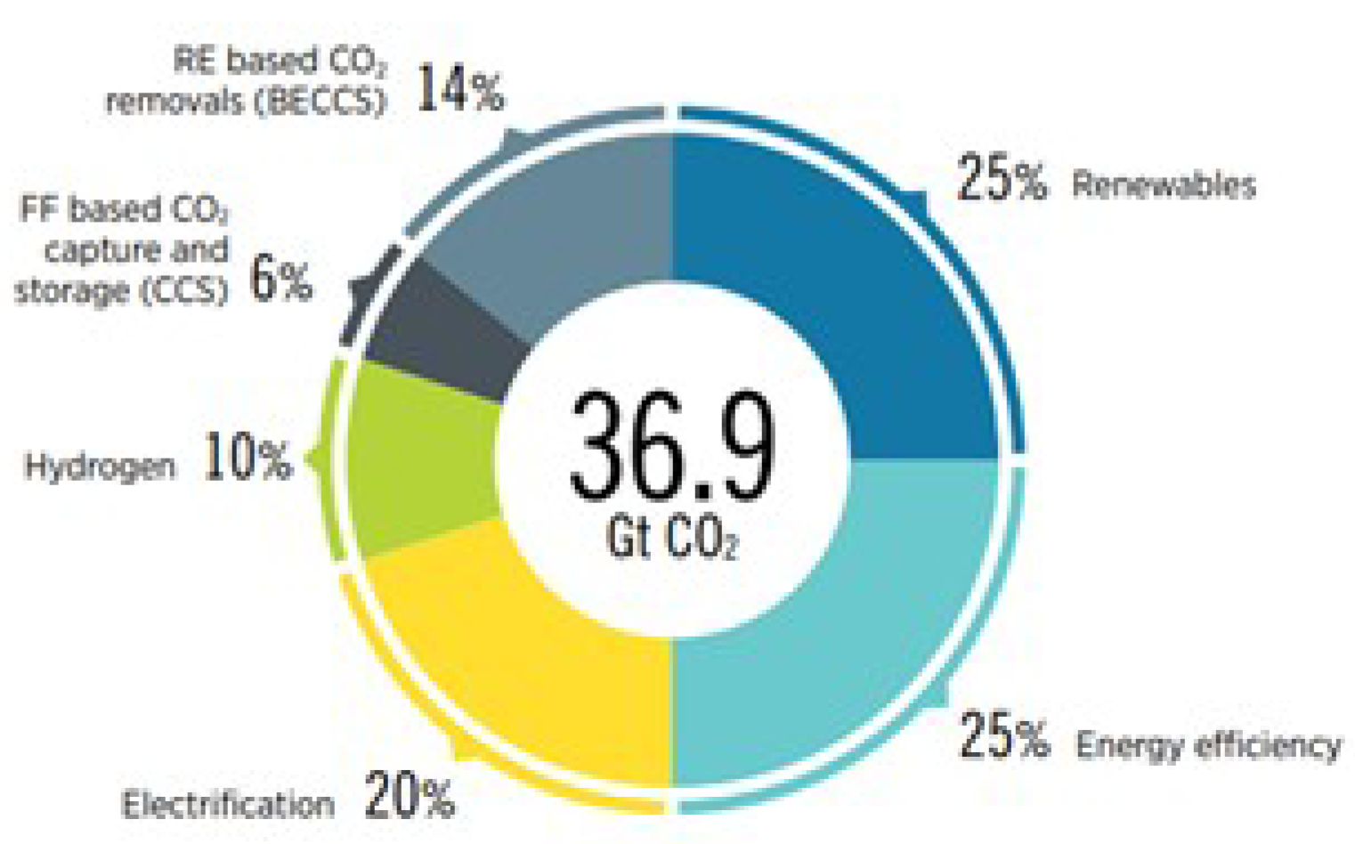
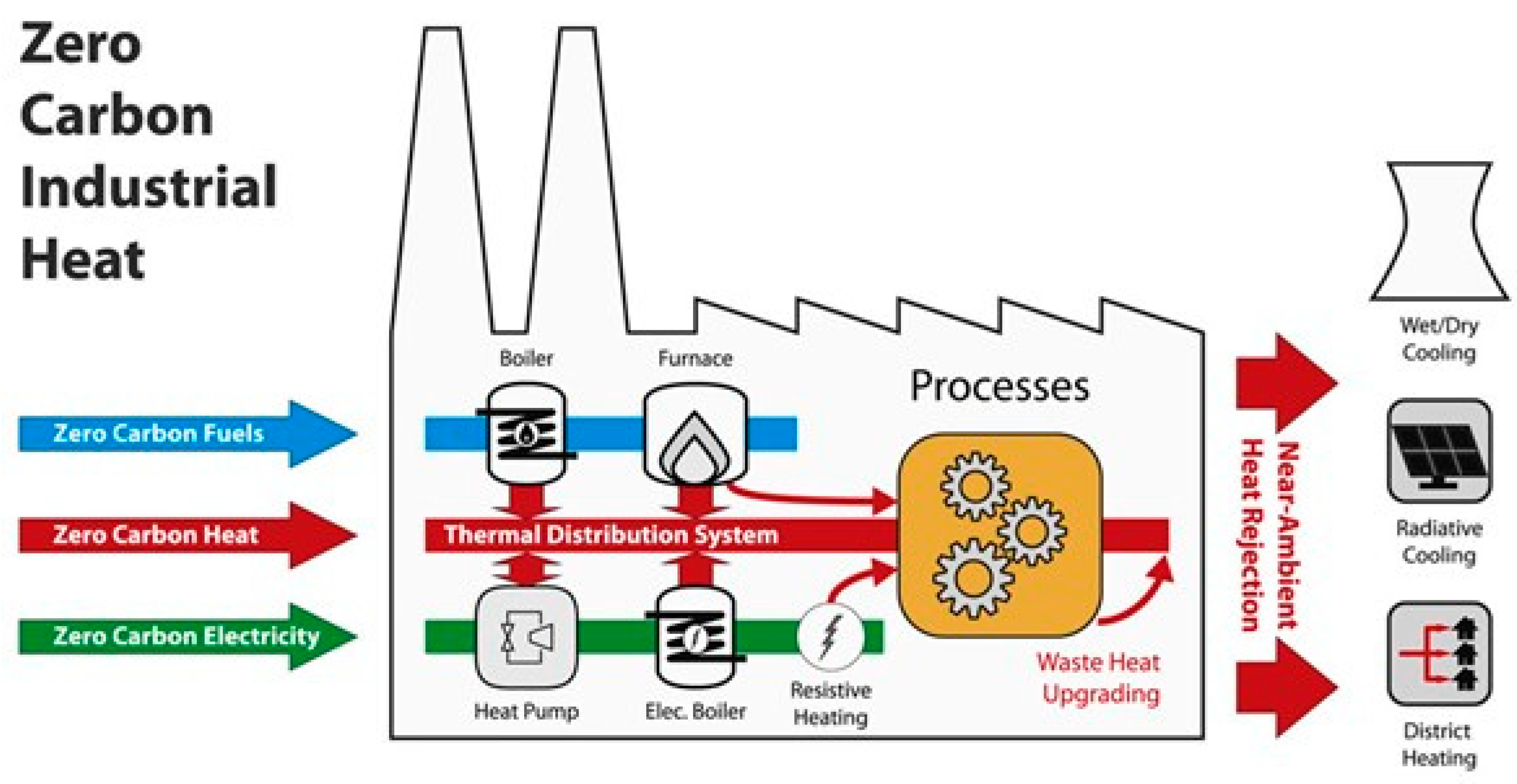
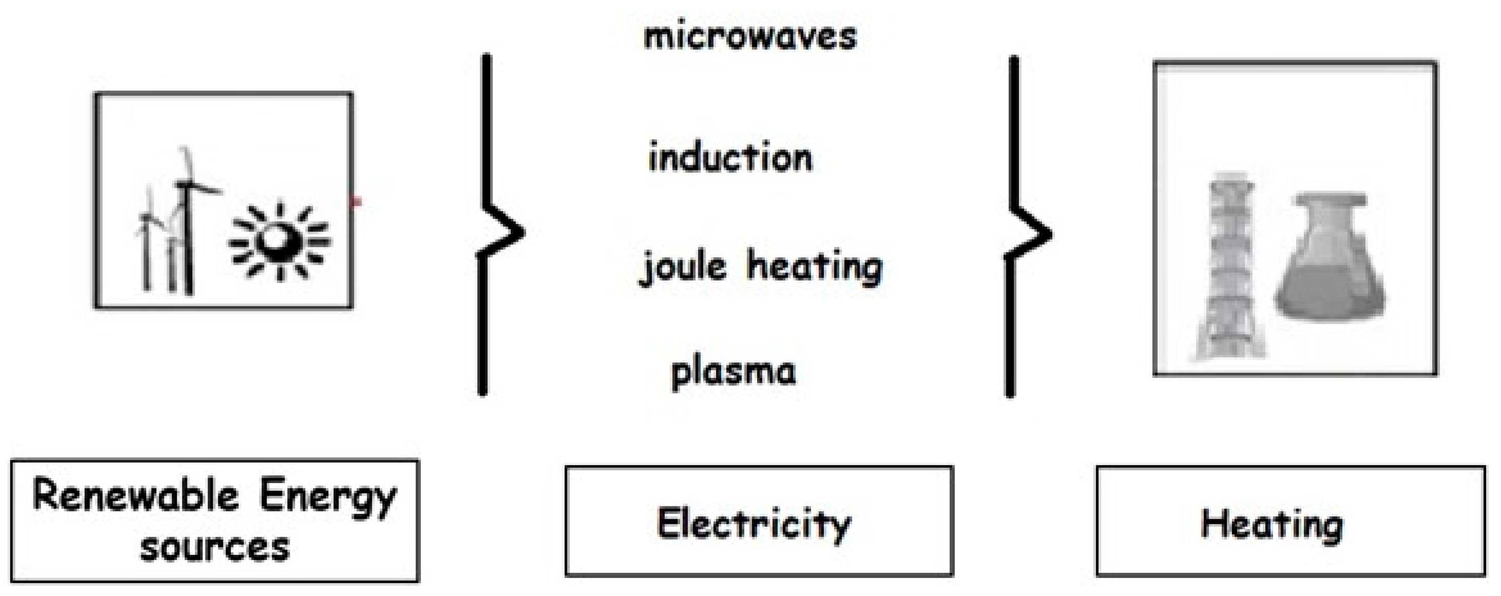
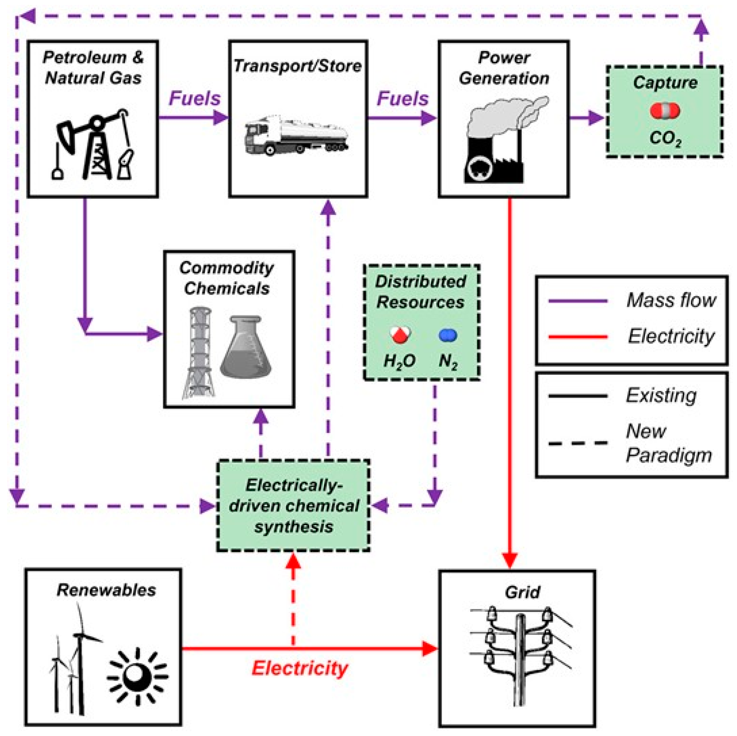
:1. Introduction
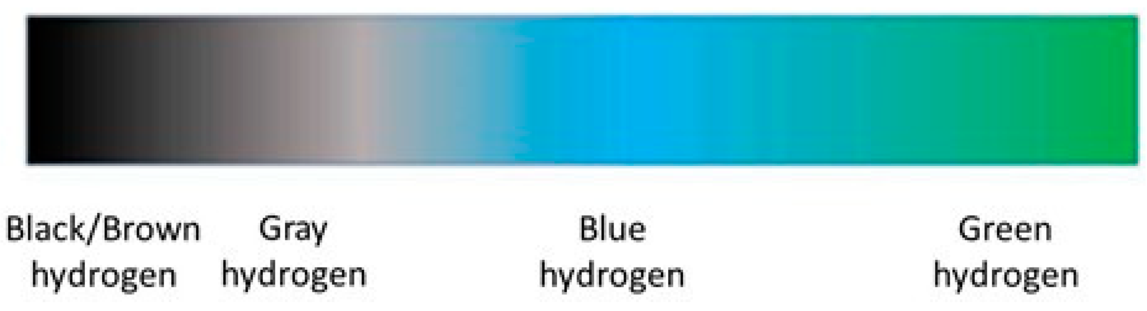
2. Hydrogen Production
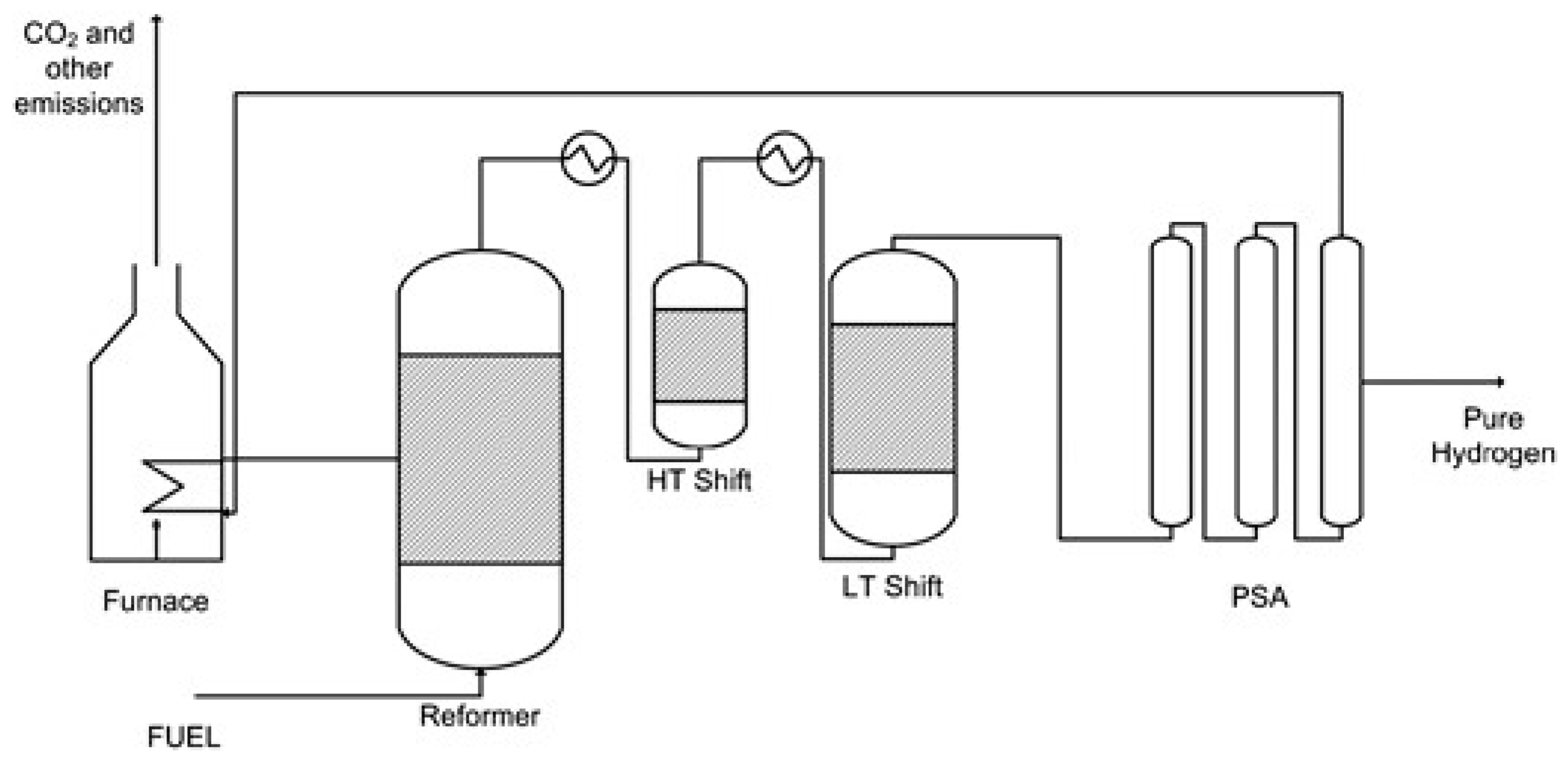
2.1. SMR
2.2. Water Electrolysis

| AECs | PEMECs | PCECs | SOECs | |
|---|---|---|---|---|
| HER | 2H2O +2e− → H2 + 2OH− | 2H+ + 2e− → H2 | 2H+ + 2e− → H2 | H2O + 2e− → H2 + O2− |
| OER | 2OH− → ½ O2 + H2O + 2e− | H2O → ½ O2 + 2H+ + 2e− | H2O → ½ O2 + 2H+ + 2e− | O 2− → ½ O2 + 2e− |
| Charge carrier | OH− | H+ | H+ | O2− |
| Electrolyte | NaOH/KOH solution | Polymers | Ceramics | Ceramics |
| Electrocatalyst | Ni | Pt/C IrO2 | Ceramics and cermets | Ceramics and cermets |
| Temperature (°C) | 25–100 (low range) 100–250 (high range) | 25–100 (low range) 100–250 (high range) | 550–700 | >700 |
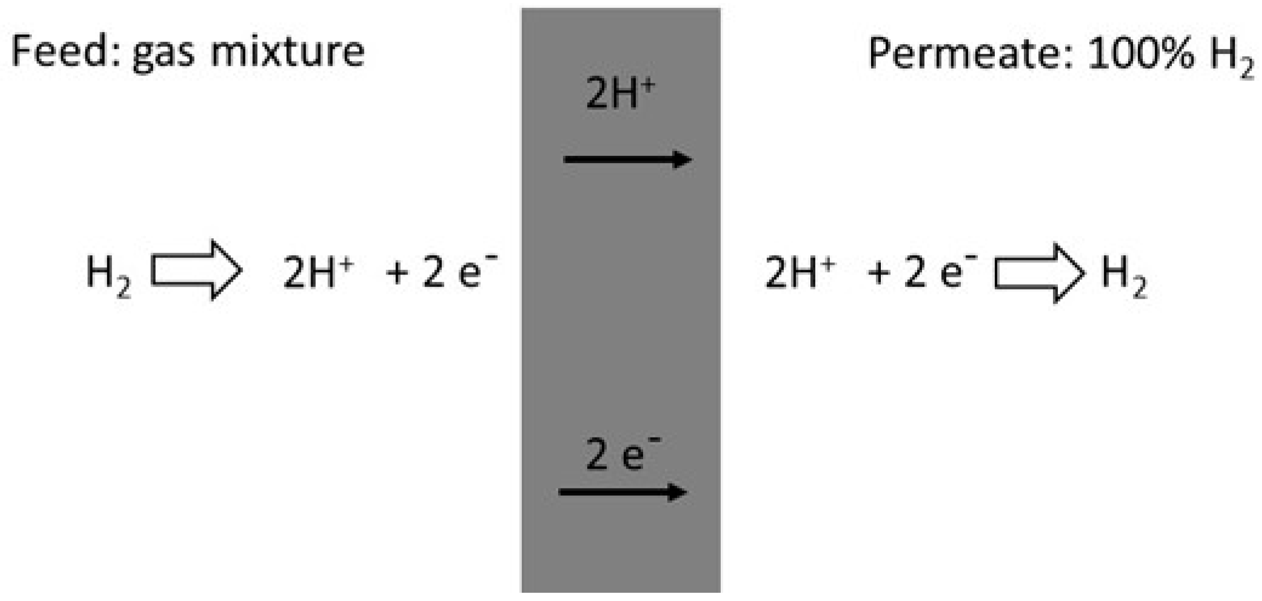
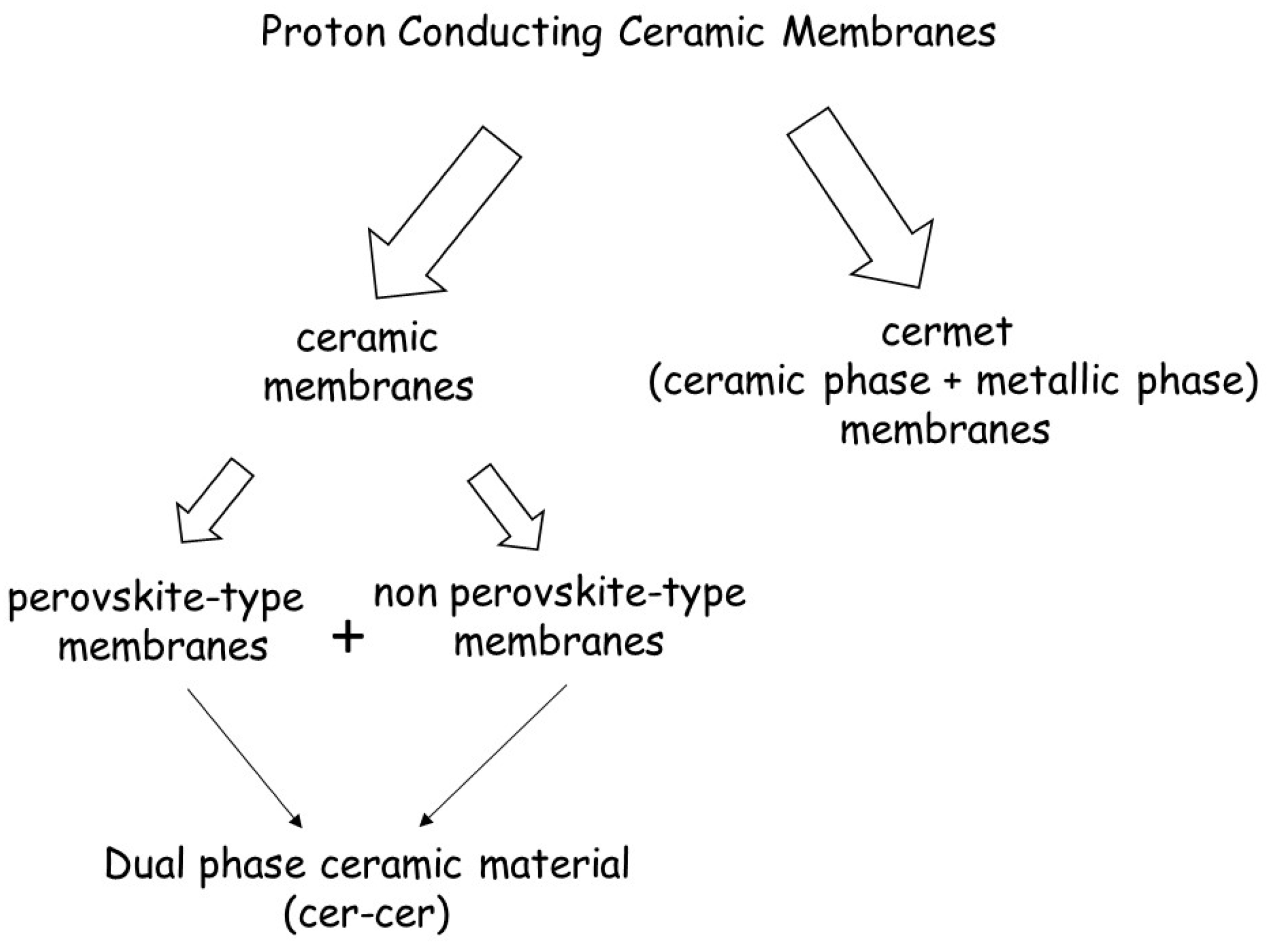
3. Proton Conducting Ceramic Membranes: General Considerations
- (1)
- Cermet membranes, consisting of a combination of a ceramic phase and a metallic phase. The metal is used as the electron-conducting phase and the ceramic oxide serves as the proton-conducting phase. Combining these two phases together may lead to high h2 permeation because both σh+ and σel are high;
- (2)
- Single-phase ceramic oxides membranes, which simultaneously transport protons and electrons.
- (3)
- Cer-cer membranes, i.e., dual-phase ceramic oxides membranes, which combine a protonic conducting perovskite phase and electronic (non-perovskite) phase.
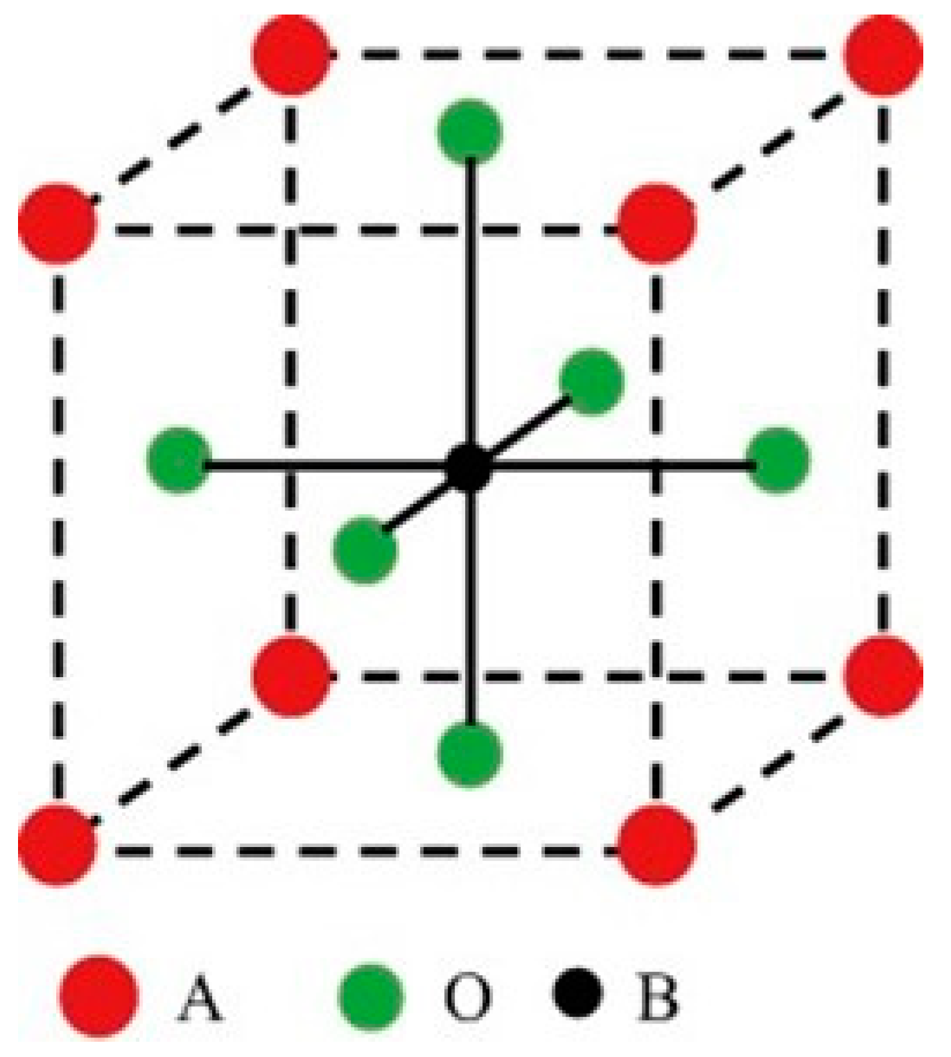
3.1. Perovskite-Type Ceramic Membranes
3.2. Non-Perovskite-Type Ceramic Membranes
3.3. Cer-Cer Dual-Phase Ceramic Membranes
3.4. Cermet Membranes
| Material | Gas Atmosphere Feed–Sweep | T (°C) | JH2, Norm (mL·min−1 ·cm−1) | Ref. |
|---|---|---|---|---|
| Perovskite ceramic membranes | ||||
| BaCe0.80Y0.10Ru0.10O3−δ | wet H2 in Ar–Ar | 800 | 4.3 × 10⁻³ | [79] |
| BaCe0.95Nd0.05O3−δ | wet 80% H2 in He–dry Ar + Ne | 900 | 1.3 × 10⁻³ | [80] |
| BaZr0.80Y0.15Mn0.05O3−δ | wet 50% H2 in He–wet Ar | 900 | 1.4 × 10⁻³ | [81] |
| SrCe0.95Tm0.05O3−δ | 10% H2 in He–air | 700–900 | 1.2 × 10⁻³/1.9 × 10−3 | [82] |
| SrCe0.95Tm0.05O3−δ | 10% H2 in He–air | 700–900 | 2.6 × 10⁻³/6.4 × 10−3 | [83] |
| SrCe0.95Tm0.05O3−δ | 10% H2 dry in He–20% O2 in Ar | 750/900 | 4.3 × 10⁻³/6.8 × 10−3 | [84] |
| SrCe0.95Tb0.05O3−δ | 20% H2 in He–CO in Ar | 750/900 | 4.0 × 10⁻⁴/1.6 × 10−3 | [85] |
| SrCe0.95Y0.05O3−δ | 80% H2 in He–Ar | 900 | 3.2 × 10⁻⁴ | [86] |
| SrCe0.95Y0.05O3−δ | 10% H2 in He–air | 677 | 2.7 × 10⁻³ | [87] |
| SrCe0.95Eu0.05O3−δ | 100% H2–He | 700–850 | 2.3 × 10⁻⁴/7.4 × 10−4 | [88] |
| SrCe0.95Sm0.05O3−δ | 100% H2–He | 850 | 5.4 × 10⁻⁴ | [88] |
| SrCe0.75Zr0.20Tm0.05O3−δ | H2 in He–wet Ar | 750/900 | 5.0 × 10⁻³ | [89] |
| SrCe0.75Zr0.20Tm0.05O3−δ | 10% H2 dry in He–20% O2 in Ar | 900 | 8.0 × 10⁻⁴/2.4 × 10−3 | [84] |
| SrCe0.70Zr0.25Ln0.05O3−δ (Ln = Tm, Yb) | wet 20% H2–wet sweep (not specified) | 900 | 2.3 × 10⁻⁴ | [90] |
| SrCe0.65Zr0.20Eu0.15O3−δ | 100% H2–He | 900 | 8.5 × 10⁻⁴ | [91] |
| SrZr0.95Y0.05O3−δ | 20% H2–air in He | 700 | <2.3 × 10⁻⁵ | [87] |
| Non-perovskite ceramic membranes | ||||
| La5.5WO11.25−δ | wet 50% H2 in He–wet Ar | 750/900 | 1.5 × 10⁻³/4.7 × 10−3 | [92] |
| La5.5W0.8Mo0.2O11.25−δ | wet 50% H2 in He–wet Ar | 700 | 2.7 × 10⁻³ | [92] |
| La5.5W0.8Re0.2O11.25−δ | wet 50% H2 in He–wet Ar | 700 | 5.9 × 10⁻³ | [92] |
| Nd5.5WO11.25−δ | wet 20% H2 in He–wet Ar | 1000 | 1.2 × 10⁻³ | [93] |
| (Nd5/6La1/6)5.5WO12−δ | wet 50% H2 in He–wet Ar | 900 | 1.2 × 10⁻³ | [94] |
| (La5/6Nd1/6)5.5WO12−δ | wet 50% H2 in He–wet Ar | 900 | 1.4 × 10⁻³ | [95] |
| Nd5.5W0.5Mo0.5O11.25−δ | wet 50% H2 in He–wet Ar | 900 | 7.5 × 10⁻³ | [96] |
| Nd5.5W0.5Re0.5O11.25−δ | wet 50% H2 in He–wet Ar | 900 | 4.1 × 10⁻³ | [97] |
| Cer-Cer dual phase membranes | ||||
| La5.5WO11.25−δ:La0.87Sr0.13CrO3−δ (50:50 vol.%) | wet 50% H2 in He–wet Ar | 700 | 5.5 × 10⁻³ | [98] |
| BaCe0.80Eu0.20O3−δ:Ce0.80Eu0.20O2−δ (50:50 vol.%) | H2, CH4, H2O, CO, CO2–He | 900 | <7.0 × 10⁻² | [78] |
| BaCe0.80Y0.20O3−δ:Ce0.80Y0.20O2−δ (50:50 wt.%) | wet 50% H2 in He–wet Ar | 900 | 1.1 × 10⁻² | [99] |
| BaCe0.65Zr0.20Y0.15O3−δ:Ce0.85Gd0.15O2−δ (50:50 vol.%) | wet 50% H2 in He–wet Ar | 755 | 1.76 × 10⁻² | [100] |
| BaCe0.20Zr0.70Y0.10O3−δ:Sr0.95Ti0.90Ni0.10O3−δ (50:50 vol.%) | 9% H2 in He–dry Ar | 800 | 1.1 × 10⁻³ | [101] |
| SrZrO3:SrFeO3 (80:20 vol.%) | H2 in He–wet Ar | 900 | 4.8 × 10⁻³ | [102] |
| Cermet membranes | ||||
| BaCe0.95Tb0.05O3−δ:Ni (50:50 wt.%) | 50% H2 in N2–He | 850 | 8.3 × 10⁻³ | [103] |
| BaCe0.90Y0.10O3−δ:Ni (60:40 vol.%) | 4% H2 in He–100 ppm H2 in N2 | 800 | 1.7 × 10⁻² | [104] |
| BaCe0.80Y0.20O3−δ:Ni (60:40 vol.%) | 3.8% H2 in N2–100 ppm H2 in N2 | 900 | 2.0 × 10⁻³ | [105] |
| BaCe0.85Zr0.10Tb0.05O3−δ:Ni (50:50 wt.%) | 50% H2 in 50% He–Ar | 800 | 8.5 × 10⁻³ | [106] |
| BaCe0.70Zr0.10Y0.20O3−δ:Ni (60:40 vol.%) | 4% H2 in He–100 ppm H2 in N2 | 900 | 5.6 × 10⁻³ | [107] |
| BaCe0.70Zr0.10Y0.10Yb0.10O3−δ:Ni (60:40 vol.%) | 20% H2–wet, 60% CO2, 20% He–N2 | 900 | 3.5 × 10⁻³ | [108] |
| Ce0.50La0.4875Ca0.0125O2−δ:Ni (60:40 vol.%) | wet 20% H2, 77% N2–Ar | 900 | 1.5 × 10⁻³ | [109] |
| YSZ:Pd (40:60 vol.%) | 90% H2 in He–N2 | 400/900 | 4.7 × 10⁻²/9.4 × 10−2 | [110] |
4. Applications of Proton-Conducting Ceramic Membranes to Produce Decarbonized H2
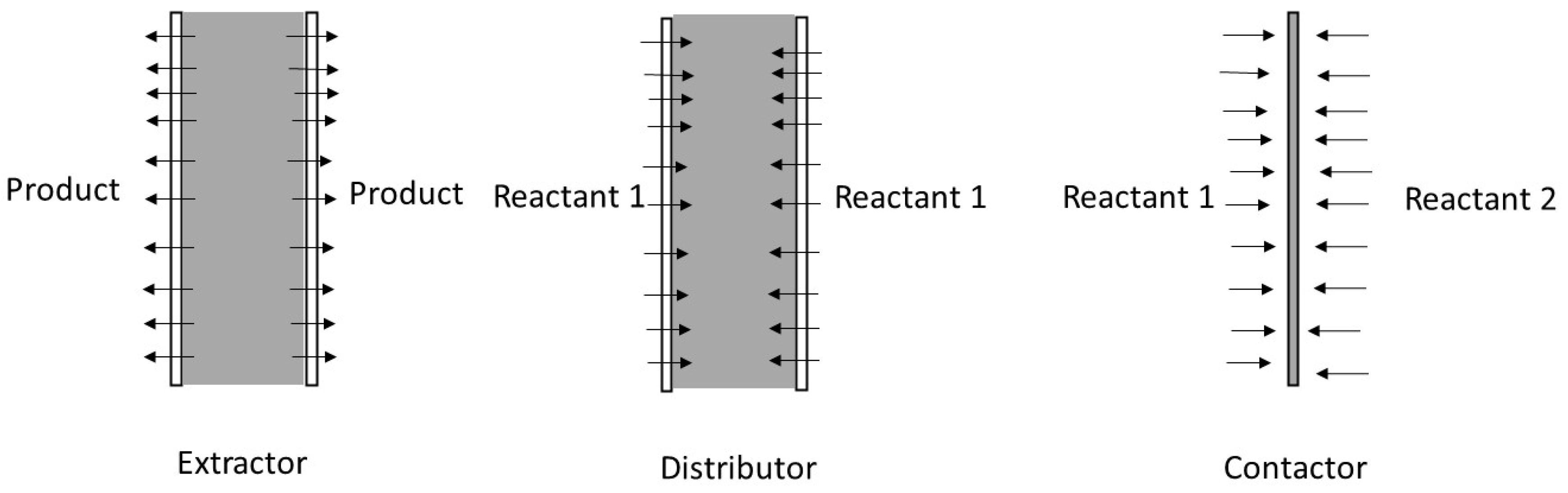
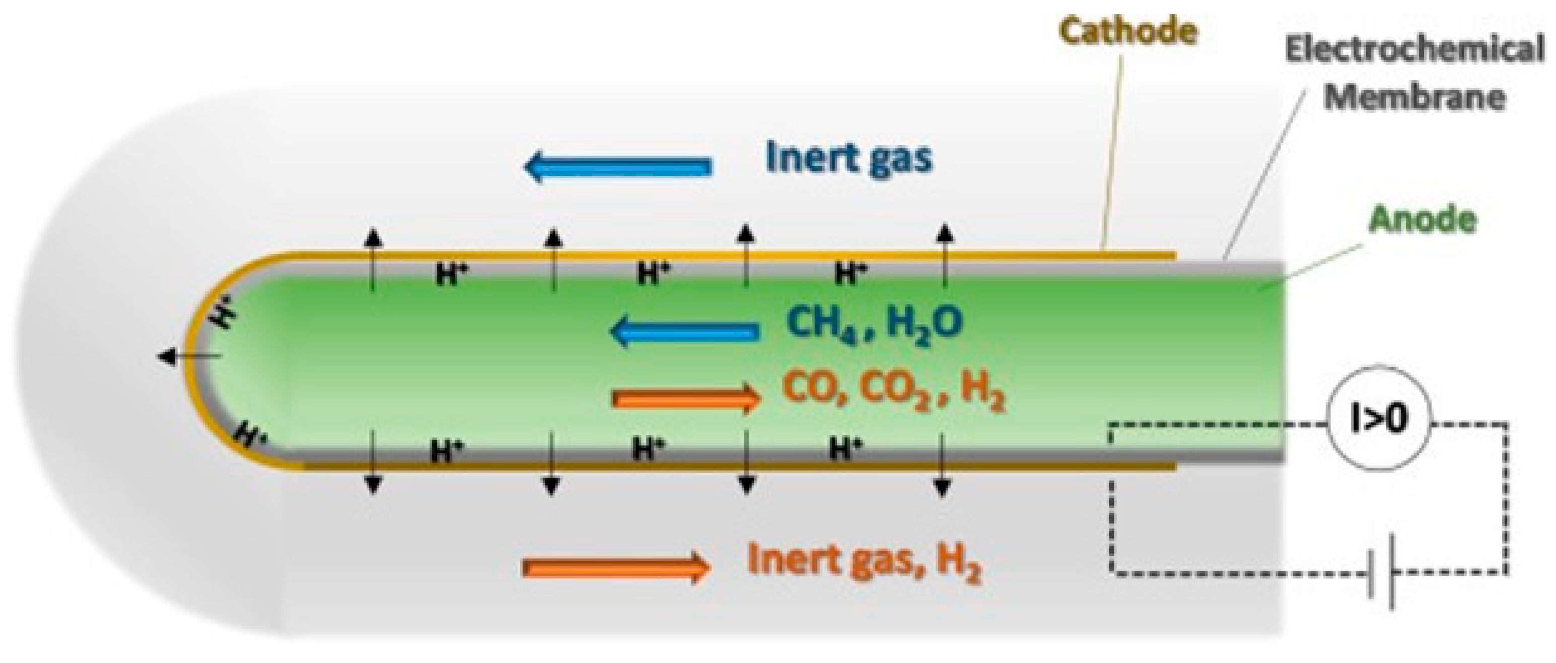
4.1. PCMRs
- (i).
- It can be used to extract a reaction product from the reaction zone in the so-called extractor.
- (ii).
- It can control the introduction of one of the reactants into the reaction zone in the so-called distributor.
- (iii).
- It can facilitate the contact between reactants and catalyst in the so-called contactor.
4.2. RePCECs
5. Conclusions and Outlook
- (i).
- The defect chemistry and transport properties of proton-conducting ceramic membranes and positive electrode materials as well as the relationship of defect chemistry and transport properties of these materials with composition, stoichiometry, microstructure, and operating conditions.
- (ii).
- The design of positive electrodes for PCECs and RePCECs to enhance bulk proton conductivity.
- (iii).
- The development of appropriate catalysts with specific activities for natural gas reforming and compatibility with other components of protonic ceramic devices.
- (iv).
- The engineering of the interface between the catalyst and the negative electrode to tune the electrochemical reactions.
Funding
Data Availability Statement
Conflicts of Interest
References
- World Energy Transitions Outlook: 1.5 °C, Irena. 2022. Available online: https://www.irena.org/Publications/2023/Jun/World-Energy-Transitions-Outlook-2023#:~:text=IRENA’s%201.5%C2%B0C%20Scenario,clean%20hydrogen%20and%20sustainable%20biomass (accessed on 18 August 2023).
- Li, S.; Zhang, H.; Nie, J.; Dewil, R.; Baeyens, J.; Deng, Y. The Direct Reduction of Iron Ore with Hydrogen. Sustainability 2021, 13, 8866. [Google Scholar] [CrossRef]
- Li, S.; Kang, Q.; Baeyens, J.; Zhang, H.L.; Deng, Y.M. Hydrogen Production: State of Technology. IOP Conf. Ser. Earth Environ. Sci. 2020, 544, 012011. [Google Scholar] [CrossRef]
- Baeyens, J.; Zhang, H.; Nie, J.; Appels, L.; Dewil, R.; Ansart, R.; Deng, Y. Reviewing the potential of bio-hydrogen production by fermentation. Renew. Sustain. Energy Rev. 2020, 131, 110023. [Google Scholar] [CrossRef]
- Chao, C.; Deng, Y.; Dewil, R.; Baeyens, J.; Fan, X. Post-combustion carbon capture. Renew. Sustain. Energy Rev. 2021, 138, 110490. [Google Scholar] [CrossRef]
- Schiffer, Z.J.; Manthiram, K. Electrification and Decarbonization of the Chemical Industry. Joule 2017, 1, 10–14. [Google Scholar] [CrossRef]
- Henry, A.; Prasher, R.; Majumdar, A. Five thermal energy grand challenges for decarbonization. Nat. Energy 2020, 5, 635–637. [Google Scholar] [CrossRef]
- Rightor, E.; Whitlock, A.; Elliott, R.N. Beneficial Electrification in Industry; Research Report; American Counsil for an Energy-Efficient Economy: Washington, DC, USA, 2020. [Google Scholar]
- Savut, I. Industrial Heat: Deep Decarbonization Opportunities. Bloomberg New Energy Finance, 2019. [Google Scholar]
- Global Carbon Project. Supplemental Data of Global Carbon Budget 2019 (Version 1.0) [Data Set]. Available online: https://www.icos-cp.eu/science-and-impact/global-carbon-budget/2019 (accessed on 18 August 2023). [CrossRef]
- Thiel, G.P.; Stark, A.K. To decarbonize industry, we must decarbonize heat. Joule 2021, 5, 531–550. [Google Scholar] [CrossRef]
- Colbertaldo, P.; Guandalini, G.; Campanari, S. Modelling the Integrated Power and Transport Energy System: The Role of Power-To-Gas and Hydrogen in Long-Term Scenarios for Italy. Energy 2018, 154, 592–601. [Google Scholar] [CrossRef]
- Buonomenna, M.G. Nano-Enhanced and Nanostructured Polymer-Based Membranes for Energy Applications, 1st ed.; Woodhead Publishing: Sawston, UK, 2022. [Google Scholar]
- Atwell, C. 6 Promising Energy Storage Options to Tie to the Grid. Power Electronics. 2018. Available online: https://www.electronicdesign.com/technologies/power/alternative-energy/article/21199504/6-promising-energy-storage-options-to-tie-into-the-grid (accessed on 18 August 2023).
- Deng, Y.; Li, S.; Dewil, R.; Appels, L.; Yang, M.; Zhang, H.; Baeyens, J. Water splitting by MnFe2O4/Na2CO3 reversible redox reactions. RSC Adv. 2022, 12, 31392–31401. [Google Scholar] [CrossRef]
- Deng, Y.; Dewil, R.; Appels, L.; Li, S.; Baeyens, J.; Degrève, J.; Wang, G. Thermo-chemical water splitting: Selection of priority reversible redox reactions by multi-attribute decision making. Renew. Energy 2021, 170, 800–810. [Google Scholar] [CrossRef]
- Safari, F.; Dincer, I. A review and comparative evaluation of thermochemical water splitting cycles for hydrogen production. Energy Convers. Manag. 2020, 205, 112182. [Google Scholar] [CrossRef]
- Available online: https://www.nationalgrid.com/stories/energy-explained/hydrogen-colour-spectrum#:~:text=Blue%20hydrogen%20is%20produced%20mainly,produced%20as%20a%20by%2Dproduct (accessed on 18 August 2023).
- Sandalow, D.; Friedmann, J.; Aines, R.; McCormick, C.; McCoy, S.; Stolaroff, J. ICEF Industrial Heat Decarbonization Roadmap; ICEF (Innovation for Cool Earth Forum): Tokyo, Japan, 2019. [Google Scholar]
- Rostrup-Nielsen, J.; Christiansen, L.J. Concepts in Syngas Manufacture; Imperial College Press: London, UK, 2011. [Google Scholar]
- Kumar, A.; Baldea, M.; Edgar, T.F. A Physics-Based Model for Industrial Steam-Methane Reformer Optimization with Non-Uniform Temperature Field. Comput. Chem. Eng. 2017, 105, 224–236. [Google Scholar] [CrossRef]
- Latham, D.A.; McAuley, K.B.; Peppley, B.A.; Raybold, T.M. Mathematical Modeling of an Industrial Steam-Methane Reformer for on-Line Deployment. Fuel Process. Technol. 2011, 92, 1574–1586. [Google Scholar] [CrossRef]
- Gallucci, F.; Fernandez, E.; Corengia, P.; van Sint Annaland, M. Recent advances on membranes and membrane reactors for hydrogen production. Chem. Eng. Sci. 2013, 92, 40–66. [Google Scholar] [CrossRef]
- Wismann, S.T.; Engbæk, J.S.; Vendelbo, S.B.; Eriksen, W.L.; Frandsen, C.; Mortensen, P.M.; Chorkendorff, I. Electrified methane reforming: Elucidating transient phenomena. Chem. Eng. J. 2021, 425, 131509. [Google Scholar] [CrossRef]
- Le Qu’er´e, N.; Moriarty, C.; Andrew, R.; Peters, R.M.; Ciais, G.P.; Friedlingstein, P.; Jones, S.D.; Sitch, S.; Tans, P.; Arneth, A.; et al. Global Carbon Budget 2018. Earth Syst. Sci. Data. 2018, 10, 2141–2194. [Google Scholar] [CrossRef]
- Wismann, S.T.; Engbæk, J.S.; Vendelbo, S.B.; Bendixen, F.B.; Eriksen, W.L.; Aasberg-petersen, K.; Frandsen, C.; Chorkendorff, I.; Mortensen, P.M. Electrified methane reforming: A compact approach to greener industrial hydrogen production. Science 2019, 364, 756–759. [Google Scholar]
- Almind, M.R.; Vendelbo, S.B.; Hansen, M.F.; Vinumd, M.G.; Frandsen, C.; Mortensene, P.M.; Engbæk, J.S. Improving performance of induction-heated steam methane reforming. Catal. Today 2020, 342, 13–20. [Google Scholar] [CrossRef]
- Available online: https://energiforskning.dk/sites/energiforskning.dk/files/slutrapporter/induction_heated_hydrogen_production_-_eudp_project_no_64013-0511_-_final_report.pdf (accessed on 18 August 2023).
- Scarfiello, C.; Bellusci, M.; Pilloni, L.; Pietrogiacomi, D.; La Barbera, A.; Varsano, F. Supported catalysts for induction-heated steam reforming of methane. Int. J. Hydrog. Energy 2021, 46, 134–145. [Google Scholar] [CrossRef]
- Wismann, S.T.; Engbæk, J.S.; Vendelbo, S.B.; Eriksen, W.L.; Frandsen, C.; Mortensen, P.M.; Chorkendorff, I. Electrified Methane Reforming: Understanding the Dynamic Interplay. Ind. Eng. Chem. Res. 2019, 58, 23380–23388. [Google Scholar] [CrossRef]
- Ambrosetti, M.; Beretta, A.; Groppi, G.; Tronconi, E. A Numerical Investigation of Electrically-Heated Methane Steam Reforming Over Structured Catalysts. Front. Chem. Eng. 2021, 3, 747636. [Google Scholar] [CrossRef]
- Lu, Y.R.; Nikrityuk, P.A. Steam methane reforming driven by the Joule heating. Chem. Eng. Sci. 2022, 251, 117446. [Google Scholar] [CrossRef]
- Zheng, L.; Ambrosetti, M.; Marangoni, D.; Beretta, A.; Groppi, G.; Tronconi, E. Electrified methane steam reforming on a washcoated SiSiC foam for low-carbon hydrogen production. AIChE J. 2023, 69, e17620. [Google Scholar] [CrossRef] [PubMed]
- Feng, J.; Sun, X.; Li, Z.; Hao, X.; Fan, M.; Ning, P.; Li, K. Plasma-Assisted Reforming of Methane. Adv. Sci. 2022, 9, 2203221. [Google Scholar] [CrossRef]
- Dinh, D.K.; Trenchev, G.; Lee, D.H.; Bogaerts, A. Arc Plasma Reactor Modification for Enhancing Performance of Dry Reforming of Methane. J. CO2 Util. 2020, 42, 101352. [Google Scholar] [CrossRef]
- Pérez-Camacho, M.N.; Abu-Dahrieh, J.; Rooney, D.; Sun, K. Biogas Reforming Using Renewable Wind Energy and Induction Heating. Catal. Today 2015, 242, 129–138. [Google Scholar] [CrossRef]
- de Dios García, I.; Stankiewicz, A.; Nigar, H. Syngas Production via Microwave-Assisted Dry Reforming of Methane. Catal. Today 2021, 362, 72–80. [Google Scholar] [CrossRef]
- Palma, V.; Barba, D.; Cortese, M.; Martino, M.; Renda, S.; Meloni, E. Microwaves and Heterogeneous Catalysis: A Review on Selected Catalytic Processes. Catalysts 2020, 10, 246. [Google Scholar] [CrossRef]
- Heijkers, S.; Aghaei, M.; Bogaerts, A. Plasma-Based CH4 Conversion into Higher Hydrocarbons and H2: Modeling to Reveal the Reaction Mechanisms of Different Plasma Sources. J. Phys. Chem. C Nanomater. Interfaces 2020, 124, 7016–7030. [Google Scholar] [CrossRef] [PubMed]
- Zheng, L.; Ambrosetti, M.; Beretta, A.; Groppi, G.; Tronconi, E. Electrified CO2 valorization driven by direct Joule heating of catalytic cellular substrates. Chem. Eng. J. 2023, 466, 143154. [Google Scholar] [CrossRef]
- Dou, L.; Yan, C.; Zhong, L.; Zhang, D.; Zhang, J.; Li, X.; Xiao, L. Enhancing CO2 Methanation over a Metal Foam Structured Catalyst by Electric Internal Heating. Chem. Commun. 2020, 56, 205–208. [Google Scholar] [CrossRef]
- Badakhsh, A.; Kwak, Y.; Lee, Y.-J.; Jeong, H.; Kim, Y.; Sohn, H.; Nam, S.W.; Yoon, C.W.; Park, C.W.; Jo, Y.S. A Compact Catalytic Foam Reactor for Decomposition of Ammonia by the Joule-Heating Mechanism. Chem. Eng. J. 2021, 426, 130802. [Google Scholar] [CrossRef]
- Gorky, F.; Lucero, J.M.; Crawford, J.M.; Blake, B.A.; Guthrie, S.; Carreon, M.A.; Carreon, M.L. Insights on cold plasma ammonia synthesis and decomposition using alkaline earth metal-based perovskites. Catal. Sci. Technol. 2021, 11, 5109–5118. [Google Scholar] [CrossRef]
- Andersen, J.A.; Christensen, J.M.; Østberg, M.; Bogaerts, A.; Jensen, A.D. Plasma-catalytic ammonia decomposition using a packed-bed dielectric barrier discharge reactor. Int. J. Hydrogen Energy 2022, 47, 32081–32091. [Google Scholar] [CrossRef]
- Seyfeli, R.C.; Varisli, D. Performance of microwave reactor system in decomposition of ammonia using nickel based catalysts with different supports. Int. J. Hydrogen Energy 2022, 47, 15175–15188. [Google Scholar] [CrossRef]
- Microwave-enhanced catalytic ammonia synthesis under moderate pressure and temperature. Catal. Commun. 2021, 159, 106344. [CrossRef]
- Miller, H.A.; Bouzek, K.; Hnat, J.; Loos, S.; Bernacker, C.I.; Weißgarber, T.; Rontzsch, L.; Meier-Haack, J. Green hydrogen from anion exchange membrane water electrolysis: A review of recent developments in critical materials and operating conditions. Sustain. Energy Fuels 2020, 4, 2114–2133. [Google Scholar] [CrossRef]
- Ebbesen, S.D.; Jensen, S.H.; Hauch, A.; Mogensen, M.B. High temperature electrolysis in alkaline cells, solid proton conducting cells, and solid oxide cells. Chem. Rev. 2014, 114, 10697–10734. [Google Scholar] [CrossRef] [PubMed]
- Zhang, W.; Liu, M.; Gu, X.; Shi, Y.; Deng, Z.; Ca, N. Water Electrolysis toward Elevated Temperature: Advances, Challenges and Frontiers. Chem. Rev. 2023, 123, 7119–7192. [Google Scholar] [CrossRef] [PubMed]
- Buonomenna, M.G. Membrane processes for a sustainable industrial growth. RSC Adv. 2013, 3, 5694–5740. [Google Scholar] [CrossRef]
- Noble, R.D.; Stern, S.A. Membrane separations technology: Principles and applications. In Membrane Science and Technology; Elsevier Science: Amsterdam, The Netherlands, 1995. [Google Scholar]
- Kluiters, S.C.A. Energy Research Centre of The Netherlands; TNO: Petten, The Netherlands, 2004. [Google Scholar]
- Ivanova, M.E.; Escolástico, S.; Balaguer, M.; Palisaitis, J.; Sohn, Y.J.; Meulenberg, W.A.; Guillon, O.; Mayer, J.; Serra, J.M. Hydrogen separation through tailored dual phase membranes with nominal composition BaCe0.8Eu0.2O3−δ:Ce0.8Y0.2O2−δ at intermediate temperatures. Sci. Rep. 2016, 6, 34773. [Google Scholar] [CrossRef]
- Phair, J.W.; Badwal, S.P.S. Review of proton conductors for hydrogen separation. Ionics 2006, 12, 103–115. [Google Scholar] [CrossRef]
- Norby, T.; Larring, Y. Mixed hydrogen ion-electronic conductors for hydrogen permeable membranes. Solid. State Ion. 2000, 136, 139–148. [Google Scholar] [CrossRef]
- Jaffe, B.; Cook, W.R.; Jaffe, H. Piezoelectric Ceramics; Academic Press: London, UK; New York, NY, USA, 1971. [Google Scholar]
- Esquirol, A.; Kilner, J.; Brandon, N. Oxygen transport in La0.6Sr0.4Co0.2Fe0.8O3d/Ce0.8Ge0.2O2x composite cathode for ITSOFCs. Solid. State Ion. 2004, 175, 63–67. [Google Scholar] [CrossRef]
- Uchida, H.; Maeda, N.; Iwahara, H. Relation between proton and hole conduction in SrCeO3-based solid electrolytes under water-containing atmospheres at high temperatures. Solid. State Ion. 1983, 11, 117–124. [Google Scholar] [CrossRef]
- Iwahara, H.; Yajima, T.; Hibino, T.; Ushida, H. Performance of solid oxide fuel cell using proton and oxide ion mixed conductors based on BaCe1xSmxO3d. J. Electrochem. Soc. 1993, 140, 1687–1691. [Google Scholar] [CrossRef]
- Bonanos, N.; Knight, K.S.; Ellis, B. Perovskite solid electrolytes: Structure, transport properties and fuel cell applications. Solid. State Ion. 1995, 79, 161–170. [Google Scholar] [CrossRef]
- Papac, M.; Stevanović, V.; Zakutayev, A.; O’Hayre, R. Triple ionic-electronic conducting oxides for next-generation electrochemical devices. Nat. Mater. 2021, 20, 301–313. [Google Scholar] [CrossRef]
- Hamakaw, S.; Li, L.; Li, A.W.; Iglesia, E. Interdiffusion in alkali ion sorption by hydrous stannic oxide: Mechanism and effect of co-ion. Solid. State Ion. 2002, 48, 71–77. [Google Scholar]
- Matsumoto, H.; Shimura, T.; Iwahara, H.; Higuchi, T.; Yashiro, K.; Kaimai, A.; Kawada, T.; Mizusaki, J. Hydrogen separation using proton-conducting perovskites. J. Alloys Compd. 2006, 408–412, 456–462. [Google Scholar] [CrossRef]
- Matsumoto, H.; Okada, S.; Hashimoto, S.; Sasaki, K.; Yamamoto, R.; Enoki, M.; Ishihara, T. Hydrogen separation from syngas using high temperature proton conductors. Ionics 2007, 13, 93–99. [Google Scholar] [CrossRef]
- Fang, S.M.; Bi, L.; Yang, C.L.; Yan, L.T.; Chen, C.S.; Liu, W. H2S poisoning and regeneration of Ni–BaZr0.1Ce0.7Y0.2O3d at intermediate temperature. J. Alloys Compd. 2009, 475, 935–939. [Google Scholar] [CrossRef]
- Fabbri, E.; Bi, L.; Pergolesi, D.; Traversa, E. Towards the next generation of solid oxide fuel cells operating below 600 c with chemically stable proton-conducting electrolytes. Adv. Mater. 2012, 24, 195–208. [Google Scholar] [CrossRef] [PubMed]
- Tao, Z.; Yan, L.; Qiao, J.; Wang, B.; Zhang, L.; Zhang, J. A review of advanced proton-conducting materials for hydrogen separation. Prog. Mater. Sci. 2015, 74, 1–50. [Google Scholar] [CrossRef]
- KQin, G.; Bao, J.; Ruan, F.; An, S.; Wang, Z.; Li, L. Enhanced grain boundary conductivity of Gd and Sc co-doping BaZrO3 proton conductor for proton ceramic fuel cell. Chem. Eng. J. 2023, 466, 143114. [Google Scholar]
- Shirpour, M.; Merkle, R.; Maier, J. Evidence for space charge effects in Y-doped BaZrO3 from reduction experiments. Solid. State Ion. 2012, 216, 1–5. [Google Scholar] [CrossRef]
- Morejudo, S.H.; Zanon, R.; Escolastico, S.; Yuste-Tirados, I.; Malerød-Fjeld, H.; Vestre, P.K.; Coors, W.G.; Martı´nez, A.; Norby, T.; Serra, J.M.; et al. Direct conversion of methane to aromatics in a catalytic co-ionic membrane reactor. Science 2016, 353, 563–566. [Google Scholar] [CrossRef] [PubMed]
- Ding, D.; Zhang, Y.; Wu, W.; Chen, D.; Liu, M.; He, T. A novel low thermal-budget approach for the co-production of ethylene and hydrogen via the electrochemical non-oxidative deprotonation of ethane. Energy Environ. Sci. 2018, 11, 1710–1716. [Google Scholar] [CrossRef]
- Malerød-Fjeld, H.; Clark, D.; Yuste-Tirados, I.; Zanon, R.; Catalan-Martinez, D.; Beeaff, D.; Morejudo, S.H.; Vestre, P.K.; Norby, T.; Haugsrud, R.; et al. Thermo-electrochemical production of compressed hydrogen from methane with near-zero energy loss. Nat. Energy 2017, 2, 923–931. [Google Scholar] [CrossRef]
- Deibert, W.; Ivanova, M.E.; Baumann, S.; Guillon, O.; Meulenberg, W.A. Ion-conducting ceramic membrane reactors for high-temperature applications. J. Membr. Sci. 2017, 543, 79–97. [Google Scholar] [CrossRef]
- Kyriakou, V.; Garagounis, I.; Vourros, A.; Vasileiou, E.; Manerbino, A.; Coors, W.G.; Stoukides, M. Methane steam reforming at low temperatures in a BaZr0.7Ce0.2Y0.1O2.9 proton conducting membrane reactor. Appl. Catal. B Environ. 2016, 186, 1–9. [Google Scholar] [CrossRef]
- Duan, C.; Kee, R.; Zhu, H.; Sullivan, N.; Zhu, L.; Bian, L.; Jennings, D.; O’Hayre, R. Highly efficient reversible protonic ceramic electrochemical cells for power generation and fuel production. Nat. Energy 2019, 4, 230–240. [Google Scholar] [CrossRef]
- Dailly, J.; Ancelin, M.; Marrony, M. Long term testing of BCZY-based protonic ceramic fuel cell PCFC: Micro-generation profile and reversible production of hydrogen and electricity. Solid. State Ion. 2017, 306, 69–75. [Google Scholar] [CrossRef]
- Chen, Y.; Liao, Q.; Li, Z.; Wang, H.H.; Wei, Y.Y.; Feldhoff, A.; Caro, J. A CO2-stable hollow-fiber membrane with high hydrogen permeation flux. AIChE J. 2015, 61, 1997–2007. [Google Scholar] [CrossRef]
- Elangovan, S.; Nair, B.G.; Small, T.A. Ceramic Mixed Protonic/Electronic Conducting Membranes for Hydrogen Separation. U.S. Patent US7258820B2, 21 August 2007. [Google Scholar]
- Matsumoto, H.; Shimura, T.; Higuchi, T.; Tanaka, H.; Katahira, K.; Otake, T.; Kudo, T.; Yashiro, K.; Kaimai, A.; Kawada, T.; et al. Protonic-electronic mixed conduction and hydrogen permeation in BaCe0.9−xY0.1RuxO3−α. J. Electrochem. Soc. 2005, 152, A488–A492. [Google Scholar] [CrossRef]
- Cai, M.; Liu, S.; Efimov, K.; Caro, J.; Feldhoff, A.; Wang, H. Preparation and hydrogen permeation of BaCe0.95Nd0.05O3−δ membranes. J. Memb. Sci. 2009, 343, 90–96. [Google Scholar] [CrossRef]
- Escolástico, S.; Ivanova, M.; Solís, C.; Roitsch, S.; Meulenberg, W.A.; Serra, J.M. Improvement of transport properties and hydrogen permeation of chemically-stable proton-conducting oxides based on the system BaZr1−x−yYxMyO3−δ. RSC Adv. 2012, 2, 4932–4943. [Google Scholar] [CrossRef]
- Cheng, S.G.; Gupta, V.K.; Lin, J.Y.S. Synthesis and hydrogen permeation properties of asymmetric proton-conducting ceramic membranes. Solid. State Ion. 2005, 176, 2653–2662. [Google Scholar] [CrossRef]
- Qi, X.W.; Lin, Y.S. Electrical conduction and hydrogen permeation through mixed proton-electron conducting strontium cerate membranes. Solid. State Ion. 2000, 130, 149–156. [Google Scholar] [CrossRef]
- Kniep, J.; Lin, Y.S. Effect of Zirconium Doping on Hydrogen Permeation through Strontium Cerate Membranes. Ind. Eng. Chem. Res. 2010, 49, 2768–2774. [Google Scholar] [CrossRef]
- Wei, X.; Kniep, J.; Lin, Y.S. Hydrogen permeation through terbium doped strontium cerate membranes enabled by presence of reducing gas in the downstream. J. Membr. Sci. 2009, 345, 201–206. [Google Scholar] [CrossRef]
- Zhan, S.; Zhu, X.; Ji, B.; Wang, W.; Zhang, X.; Wang, J.; Yang, W.; Lin, L. Preparation and hydrogen permeation of SrCe0.95Y0.05O3-δ asymmetrical membranes. J. Membr. Sci. 2009, 340, 241–248. [Google Scholar] [CrossRef]
- Hamakawa, S.; Li, L.; Li, A.; Iglesia, E. Synthesis and hydrogen permeation properties of membranes based on dense SrCe0.95Yb0.05O3-α thin films. Solid. State Ion. 2002, 148, 71–81. [Google Scholar] [CrossRef]
- Song, S.J.; Wachsman, E.D.; Rhodes, J.; Dorris, S.E.; Balachandran, U. Hydrogen permeability of SrCe1−xMxO3−δ (x= 0.05, M= Eu, Sm). Solid. State Ion. 2004, 167, 99–105. [Google Scholar] [CrossRef]
- Liang, J.; Mao, L.; Li, L.; Yuan, W. Protonic and Electronic Conductivities and Hydrogen Permeation of SrCe0.95−xZrxTm0.05O3−δ (0 <=x <=0.40) Membrane. Chin. J. Chem. Eng. 2010, 18, 506–510. [Google Scholar]
- Xing, W.; Dahl, P.I.; Roaas, L.V.; Fontaine, M.L.; Larring, Y.; Henriksen, P.P.; Bredesen, R. Hydrogen permeability of SrCe0.7Zr0.25Ln0.05O3−δ membranes (Ln = Tm and Yb). J. Membr. Sci. 2015, 473, 327–332. [Google Scholar] [CrossRef]
- Oh, T.; Yoon, H.; Li, J.; Wachsman, E.D. Hydrogen permeation through thin supported SrZr0.2Ce0.8-xEuxO3-δ membranes. J. Membr. Sci. 2009, 345, 1–4. [Google Scholar] [CrossRef]
- Escolastico, S.; Seeger, J.; Roitsch, S.; Ivanova, M.; Meulenberg, W.A.; Serra, J.M. Enhanced H2 separation through mixed proton-electron conducting membranes based on La5.5W0.8M0.2O11.25−δ. ChemSusChem 2013, 6, 1523–1532. [Google Scholar] [CrossRef]
- Escolastico, S.; Vert, V.B.; Serra, J.M. Preparation and Characterization of Nanocrystalline Mixed Proton-Electronic Conducting Materials Based on the System Ln6WO12. Chem. Mater. 2009, 21, 3079–3089. [Google Scholar] [CrossRef]
- Escolastico, S.; Solis, C.; Serra, J.M. Hydrogen separation and stability study of ceramic membranes based on the system Nd5LnWO12. Int. J. Hydrogen Energ. 2011, 36, 11946–11954. [Google Scholar] [CrossRef]
- Escolastico, S.; Solis, C.; Serra, J.M. Study of hydrogen permeation in (La5/6Nd1/6)5.5WO12−δ membranes. Solid. State Ion. 2012, 216, 31–35. [Google Scholar] [CrossRef]
- Escolastico, S.; Somacescu, S.; Serra, J.M. Tailoring mixed ionic-electronic conduction in H2 permeable membranes based on the system Nd5.5W1−xMoxO11.25−σ. J. Mater. Chem. A 2015, 3, 719–731. [Google Scholar] [CrossRef]
- Escolastico, S.; Somacescu, S.; Serra, J.M. Solid State Transport and Hydrogen Permeation in the System Nd5.5W1−xRexO11.25−δ. Chem. Mater. 2014, 26, 982–992. [Google Scholar] [CrossRef]
- Escolastico, S.; Solis, C.; Kjolseth, C.; Serra, J.M. Outstanding hydrogen permeation through CO2-stable dual-phase ceramic membranes. Energ. Environ. Sci. 2014, 7, 3736–3746. [Google Scholar] [CrossRef]
- Rosensteel, W.A.; Ricote, S.; Sullivan, N.P. Hydrogen permeation through dense BaCe0.8Y0.2O3−δ—Ce0.8Y0.2O2−δ composite-ceramic hydrogen separation membranes. Int. J. Hydrogen Energ. 2016, 41, 2598–2606. [Google Scholar] [CrossRef]
- Rebollo, E.; Mortalo, C.; Escolástico, S.; Boldrini, S.; Barison, S.; Serrab, J.M.; Fabrizioa, M. Exceptional hydrogen permeation of all-ceramic composite robust membranes based on BaCe0.65Zr0.20Y0.15O3−δ and Y- or Gd-doped ceria. Energ. Environ. Sci. 2015, 8, 3675–3686. [Google Scholar] [CrossRef]
- Fish, J.S.; Ricote, S.; O’Hayre, R.; Bonanos, N. Electrical properties and flux performance of composite ceramic hydrogen separation membranes. J. Mater. Chem. A 2015, 3, 5392–5401. [Google Scholar] [CrossRef]
- Unemoto, A.; Kaimai, A.; Sato, K.; Yashiro, K.; Matsumoto, H.; Mizusaki, J.; Amezawa, K.; Kawada, T. Hydrogen permeability and electrical properties in oxide composites. Solid. State Ion. 2008, 178, 1663–1667. [Google Scholar] [CrossRef]
- Meng, X.; Song, J.; Yang, N.; Meng, B.; Tan, X.; Ma, Z.F.; Li, K. Ni-BaCe0.95Tb0.05O3−δ cermet membranes for hydrogen permeation. J. Membr. Sci. 2012, 401, 300–305. [Google Scholar] [CrossRef]
- Kim, H.; Kim, B.; Lee, J.; Ahn, K.; Kim, H.R.; Yoon, K.J.; Kim, B.K.; Cho, Y.W.; Lee, H.W.; Lee, J.H. Microstructural adjustment of Ni–BaCe0.9Y0.1O3−δ cermet membrane for improved hydrogen permeation. Ceram. Int. 2014, 40, 4117–4126. [Google Scholar] [CrossRef]
- Song, S.J.; Moon, J.H.; Lee, T.H.; Dorris, S.E.; Balachandran, U. Thickness dependence of hydrogen permeability for NiBaCe0.8Y0.2O3−δ. Solid. State Ion. 2008, 179, 1854–1857. [Google Scholar] [CrossRef]
- Wei, Y.; Xue, J.; Fang, W.; Chen, Y.; Wang, H.; Caro, J. Enhanced stability of Zr-doped Ba(CeTb)O3−δ-Ni cermet membrane for hydrogen separation. Chem. Comm. 2015, 51, 11619–11621. [Google Scholar] [CrossRef]
- Zuo, C.; Dorris, S.E.; Balachandran, U.; Liu, M. Effect of Zr-doping on the chemical stability and hydrogen permeation of the NiBaCe0.8Y0.2O3−α mixed protonic-electronic conductor. Chem. Mater. 2006, 18, 4647–4650. [Google Scholar] [CrossRef]
- Fang, S.; Brinkman, K.S.; Chen, F. Hydrogen permeability and chemical stability of Ni-BaZr0.1Ce0.7Y0.1Yb0.1O3−δ membrane in concentrated H2O and CO2. J. Membr. Sci. 2014, 467, 85–92. [Google Scholar] [CrossRef]
- Fang, S.; Bi, L.; Yan, L.; Sun, W.; Chen, C.; Liu, W. CO2-Resistant Hydrogen Permeation Membranes Based on Doped Ceria and Nickel. J. Phys. Chem. C 2010, 114, 10986–10991. [Google Scholar] [CrossRef]
- Balachandran, U.; Lee, T.; Park, C.; Emerson, J.; Picciolo, J.; Dorris, S. Dense cermet membranes for hydrogen separation. Sep. Purif. Technol. 2014, 121, 54–59. [Google Scholar] [CrossRef]
- Duan, C.; Huang, J.; Sullivan, N.; O’Hayre, R. Proton-conducting oxides for energy conversion and storage. Appl. Phys. Rev. 2020, 7, 011314. [Google Scholar] [CrossRef]
- Pei, K.; Zhou, Y.; Xu, K.; Zhang, H.; Ding, Y.; Zhao, B.; Yuan, W.; Sasaki, K.; Choi, Y.M. Surface restructuring of a perovskite-type air electrode for reversible protonic ceramic electrochemical cells. Nat. Commun. 2022, 13, 2207. [Google Scholar] [CrossRef]
- Buonomenna, M.G.; Choi, S.H.; Drioli, E. Catalysis in polymeric membrane reactors: The membrane role. Asia-Pac. J. Chem. Eng. 2010, 5, 26–34. [Google Scholar] [CrossRef]
- Miachon, S.; Dalmon, J.A. Catalysis in membrane reactors: What about the catalyst? Top. Catal. 2004, 29, 59–65. [Google Scholar] [CrossRef]
- Clark, D.; Malerød-Fjeld, H.; Budd, M.; Yuste-Tirados, Y.; Beeaff, D.; Aamodt, S.; Nguyen, K.; Ansaloni, L.; Peters, T.; Vestre, P.K.; et al. Single-step hydrogen production from NH3, CH4, and biogas in stacked proton ceramic reactors. Science 2022, 376, 390–393. [Google Scholar] [CrossRef] [PubMed]
- Basile, A. Hydrogen Production using Pd-based membrane reactors for fuel cells. Top. Catal. 2008, 51, 107–122. [Google Scholar] [CrossRef]
- Ryu, K.H.; Haile, S. Chemical stability and proton conductivity of doped BaCeO3–BaZrO3 solid solutions. Solid. State Ion. 1999, 125, 355–367. [Google Scholar] [CrossRef]
- Ricote, S.; Bonanos, N.; Caboche, G. Water vapour solubility and conductivity study of the proton conductor BaCe(0.9−x)ZrxY0.1O(3−δ). Solid. State Ion. 2009, 180, 990–997. [Google Scholar] [CrossRef]
- Yang, L.; Wang, S.; Blinn, K.; Liu, M.; Liu, Z.; Cheng, Z.; Liu, M. Enhanced sulfur and coking tolerance of a mixed ion conductor for SOFCs: BaZr(0.1)Ce(0.7)Y(0.2−x)Yb(x)O(3−d). Science 2009, 326, 126–129. [Google Scholar] [CrossRef]
- Shirasaki, Y.; Tsuneki, T.; Ota, Y.; Yasuda, I.; Tachibana, S.; Nakajima, H.; Kobayashi, K. Development of membrane reformer system for highly efficient hydrogen production from natural gas. Int. J. Hydrog. Energy 2009, 34, 4482–4487. [Google Scholar] [CrossRef]
- Boeltken, T.; Wunsch, A.; Gietzelt, T.; Pfeifer, P.; Dittmeyer, R. Ultra-compact microstructured methane steam reformer with integrated Palladium membrane for on-site production of pure hydrogen: Experimental demonstration. Int. J. Hydrog. Energy 2014, 39, 18058–18068. [Google Scholar] [CrossRef]
- Serra, J.M. Electrifying chemistry with protonic cells. Nat. Energy 2019, 4, 178–179. [Google Scholar] [CrossRef]
- Xu, L.; Jiang, Q.; Xiao, Z.; Li, X.; Huo, J.; Wang, S.; Dai, L. Plasma-engraved Co3O4 nanosheets with oxygen vacancies and high surface area for the oxygen evolution reaction. Angew. Chem. Int. Ed. 2016, 128, 5363–5367. [Google Scholar] [CrossRef]
- Dresp, S.; Luo, F.; Schmack, R.; Kühl, S.; Gliech, M.; Strasser, P. An efficient bifunctional two-component catalyst for oxygen reduction and oxygen evolution in reversible fuel cells, electrolyzers and rechargeable air electrodes. Energy Environ. Sci. 2016, 9, 2020–2024. [Google Scholar] [CrossRef]
- Park, S.; Shao, Y.; Liu, J.; Wang, Y. Oxygen electrocatalysts for water electrolyzers and reversible fuel cells: Status and perspective. Energy Environ. Sci. 2012, 5, 9331–9344. [Google Scholar] [CrossRef]
- Pellow, M.A.; Emmott, C.J.M.; Barnhart, C.J.; Benson, S.M. Hydrogen or batteries for grid storage? A net energy analysis. Energy Environ. Sci. 2015, 8, 1938–1952. [Google Scholar] [CrossRef]
- Available online: https://fuelcellsworks.com/news/reversible-protonic-ceramic-fuel-cells-able-to-store-energy/7 (accessed on 18 August 2023).
- Putilov, L.P.; Tsidilkovski, V.I. Improving the performance of protonic ceramic fuel cells and electrolyzers: The role of acceptor impurities in oxide membranes. Energy Convers. Manag. 2022, 267, 115826. [Google Scholar] [CrossRef]
- Kreuer, K.D. Proton-Conducting Oxides. Annu. Rev. Mater. Res. 2003, 33, 333–359. [Google Scholar] [CrossRef]
- Kreuer, K.-D. Proton Conductivity: Materials and Applications. Chem. Mater. 1996, 8, 610–641. [Google Scholar] [CrossRef]
- Kreuer, K.-D.; Paddison, S.J.; Spohr, E.; Schuster, M. Transport in Proton Conductors for Fuel-Cell Applications: Simulations, Elementary Reactions, and Phenomenology. Chem. Rev. 2004, 104, 4637–4678. [Google Scholar] [CrossRef]
- Zvonareva, I.; Fu, X.-Z.; Medvedev, D.; Shao, Z. Electrochemistry and energy conversion features of protonic ceramic cells with mixed ionic-electronic electrolytes. Energy Environ. Sci. 2022, 15, 439–465. [Google Scholar] [CrossRef]


| Entry # | Process | Electrified Heat Transformation Route | Refs. |
|---|---|---|---|
| 1 | SMR | Induction | [27,28,29] |
| 2 | SMR | Joule heating | [24,26,30,31,32,33] |
| 3 | SMR | Plasma | [34] |
| 4 | Dry reforming of methane | Plasma | [34,35] |
| 5 | Biogas reforming | Induction | [36] |
| 6 | Dry reforming of methane | Microwave | [37] |
| 7 | Catalytic decomposition of methane | Plasma | [34] |
| 8 | Methane conversion to higher hydrocarbons | Microwave | [38] |
| 9 | Methane conversion to higher hydrocarbons | Plasma | [39] |
| 10 | CO2 reforming | Microwave | [38] |
| 11 | CO2 reforming | Joule heating | [40,41] |
| 12 | Decomposition of ammonia | Joule heating | [42] |
| 13 | Decomposition of ammonia | Plasma | [43,44] |
| 14 | Decomposition of ammonia | Microwave | [45,46] |
| Entry # | Reaction | Ceramic Membrane | Anodic Electrode | Cathodic Electrode | Temperature (°C) | Ref. |
|---|---|---|---|---|---|---|
| 1 | SMR | BaZr0.7Ce0.2Y0.1O2.9 | NiBZCY72 cermet | Cu | 450–650 | [74] |
| 2 | SMR | BaZr0.7Ce0.2Y0.1O3−δ (BZCY72)/BaZr0.7Ce0.1Y0.2O3−δ (BZCY71)/BaZr0.8Ce0.1Y0.1O3−δ (BZCY81) | BCZY | Ni | 800 | [72] |
| 3 | SMR | BaZr0.7Ce0.2Y0.1O3−δ (BZCY72)/BaZr0.8Ce0.1Y0.1O3−δ (BZCY81) | BCZY | Ni | 750 | [115] |
Disclaimer/Publisher’s Note: The statements, opinions and data contained in all publications are solely those of the individual author(s) and contributor(s) and not of MDPI and/or the editor(s). MDPI and/or the editor(s) disclaim responsibility for any injury to people or property resulting from any ideas, methods, instructions or products referred to in the content. |
© 2023 by the author. Licensee MDPI, Basel, Switzerland. This article is an open access article distributed under the terms and conditions of the Creative Commons Attribution (CC BY) license (https://creativecommons.org/licenses/by/4.0/).
Share and Cite
Buonomenna, M.G. Proton-Conducting Ceramic Membranes for the Production of Hydrogen via Decarbonized Heat: Overview and Prospects. Hydrogen 2023, 4, 807-830. https://doi.org/10.3390/hydrogen4040050
Buonomenna MG. Proton-Conducting Ceramic Membranes for the Production of Hydrogen via Decarbonized Heat: Overview and Prospects. Hydrogen. 2023; 4(4):807-830. https://doi.org/10.3390/hydrogen4040050
Chicago/Turabian StyleBuonomenna, Maria Giovanna. 2023. "Proton-Conducting Ceramic Membranes for the Production of Hydrogen via Decarbonized Heat: Overview and Prospects" Hydrogen 4, no. 4: 807-830. https://doi.org/10.3390/hydrogen4040050