Article

Hydrogen Jet Fire from a Thermally Activated Pressure Relief Device (TPRD) from Onboard Storage in a Naturally Ventilated Covered Car Park

1
Efectis UK/Ireland, 307 Euston Road, London NW1 3AD, UK
2
Hydrogen Safety Engineering and Research Centre (HySAFER), Ulster University, Newtownabbey BT37 0QB, UK
*
Author to whom correspondence should be addressed.
Hydrogen 2021, 2(3), 343-361; https://doi.org/10.3390/hydrogen2030018
Submission received: 9 July 2021 / Revised: 5 August 2021 / Accepted: 7 August 2021 / Published: 17 August 2021
(This article belongs to the Special Issue Feature Papers in Hydrogen)

Abstract

:
Hydrogen jet fires from a thermally activated pressure relief device (TPRD) on onboard storage are considered for a vehicle in a naturally ventilated covered car park. Computational Fluid Dynamics was used to predict behaviour of ignited releases from a 70 MPa tank into a naturally ventilated covered car park. Releases through TPRD diameters 3.34, 2 and 0.5 mm were studied to understand effect on hazard distances from the vehicle. A vertical release, and downward releases at 0°, 30° and 45° for TPRD diameters 2 and 0.5 mm were considered, accounting for tank blowdown. direction of a downward release was found to significantly contribute to decrease of temperature in a hot cloud under the ceiling. Whilst the ceiling is reached by a jet exceeding 300 °C for a release through a TPRD of 2 mm for inclinations of either 0°, 30° or 45°, an ignited release through a TPRD of 0.5 mm and angle of 45° did not produce a cloud with a temperature above 300 °C at the ceiling during blowdown. The research findings, specifically regarding the extent of the cloud of hot gasses, have implications for the design of mechanical ventilation systems.

1. Introduction

Hydrogen is typically stored onboard a vehicle as a compressed gas at 35 MPa for buses and 70 MPa for cars. The onboard storage tanks are fitted with thermally activated pressure relief devices (TPRD) to release hydrogen, avoiding tank rupture when the surrounding temperature melts the TPRD sensing element at 110 °C or above [1]. By necessity, hydrogen vehicles will be parked in garages, car parks, maintenance shops, etc. It is important to understand the hazards associated with the use of hydrogen vehicles in confined spaces in order to in turn reduce the hazard and associated risks. Safe indoor use of hydrogen has been the focus of hydrogen safety research, e.g., within the HyIndoor [2] and HyTunnel-CS [3] projects, however, car parks are an area requiring more investigation.
The release of a high mass flow rate of hydrogen through a TPRD may bring serious safety concerns in an indoor environment. Previous theoretical and numerical work by the authors on unignited releases indoors has covered momentum-dominated releases both in enclosures with minimum ventilation and in a naturally ventilated covered car park. Even unignited release from TPRD in a garage-like enclosure with limited vent size may lead to the pressure peaking phenomenon [4,5,6]. In a naturally ventilated covered car park, if there is no ignition, then understanding the release and dispersion of hydrogen and subsequent formation of a flammable cloud is the primary concern to define inherently safer conditions for TPRD release from passenger vehicles; this has been the focus of a previous study by the authors [7]. However, there is a need to understand how ignition impacts upon requirements for a safer release.
In the event of a TPRD activation, the most probable event is that the released hydrogen will ignite [8]; hence the focus of this work. There is an absence of published work on the ignited hydrogen releases in covered car parks, however, and this is an important topic with the more widespread use of indoor hydrogen vehicles. There is a need to understand the behaviour of ignited release from a TPRD to fully define inherently safer conditions for TPRD release from passenger vehicles. If the thermal effects of a TPRD release are understood, then this can be used to inform TPRD design. Both ignited and unignited releases for a typical small residential garage (4.5 × 2.6 × 2.6 m) [9] from a TPRD = 3.34 mm were numerically investigated by Brennan et al. [10] previously, and compared to understand thermal and pressure effects in scenarios with limited vent size in garage-like enclosures. The ignited release, i.e., jet fire, was shown to produce an overpressure two orders of magnitude greater than the unignited release. Flame development and thermal effects for the garage and outside the vent were analysed. The work highlighted that the ignited release has the potential to cause serious safety concerns if it is not well accounted for.
In the authors’ previous study [11], a numerical model to predict the pressure peaking phenomenon for an ignited release was validated against experiments in a 1 m3 enclosure and subsequently applied to a parametric study investigating an inherently safer TPRD diameter for different residential garage vent configurations. It was found that the TPRD diameter should be reduced to a fraction of a millimetre to be used in a typical residential garage where minimal ventilation exists. The same validated numerical model is applied in this study for ignited hydrogen release in a naturally ventilated covered car park, where the enclosure volume and the vents are much larger than in the garage.
A ventilation system within a car park should serve to reduce the potential for a flammable mixture to form. In the case of hydrogen this means ensuring that the concentration of hydrogen in air is kept below 4% by volume i.e., the Lower Flammability Limit (LFL). It is recommended by existing standards that the ventilation rate is such that in the case of hydrogen the concentration does not exceed 1% by volume i.e., 25% of the LFL within the car park; this is specified in ISO/DIS 19880-1 [12], NFPA 2 [13] and IEC (60079-10) [14]. This was the focus of previous work by the authors where an unignited release was considered within the same covered car park geometry presented here [7]. The British Standard BS 7346-7:2013 [15] defining the code of practice for underground car parks is used as a reference for the natural ventilation requirements in [7] and in this work. The same code of practice provides recommendations on equipment performance in the case of mechanical ventilation as follows: “All fans intended to exhaust hot gases used within a car park ventilation system should be tested in accordance with BS EN 12101-3 to verify their suitability for operating at 300 °C for a period not less than 60 min (class F300)”. Thus, the extent of the cloud of hot gasses at 300 °C is noted in this study, as it could be used as the temperature limit that can be recorded at ventilation ducts for inherently safer operation of a mechanical ventilation system in the event of a hydrogen jet fire.
A covered car park is the term used to describe either a car park with two or more sides and a roof, or one which is underground. Covered car parks are representative of the majority constructed in recent times [16]. Whilst the heat release [17] and the smoke movement and fire spread from a car fire in a car park [18] were numerically investigated. There are limited published studies, either experimental or numerical investigating safety aspects of an ignited hydrogen release in a large, confined space such as a naturally ventilated covered car park. Greater understanding of this topic is critical to underpin the wider introduction of hydrogen vehicles and their safe use in car parks. Therefore, this is the focus of this study.

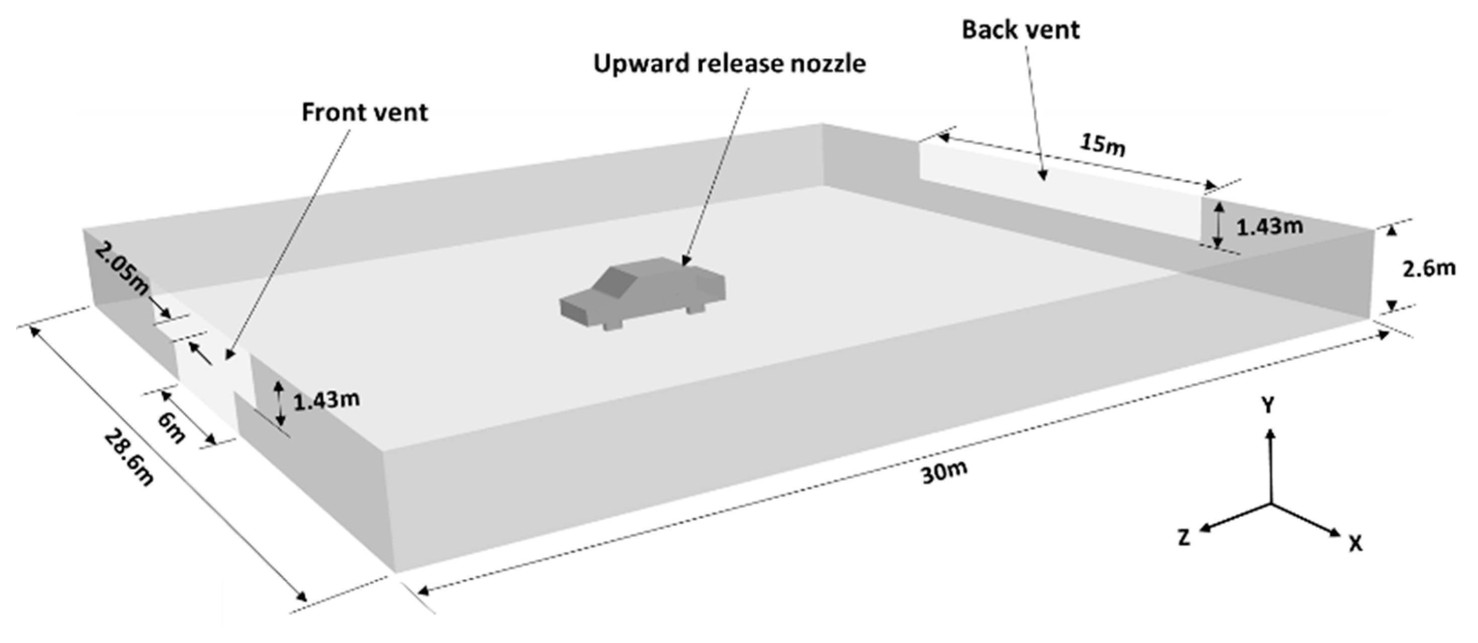
2. Problem Description

The problem description is similar to the setup described in previous work [7], with the key difference that the focus here is on ignited releases. The previous study by the authors focused on understanding the release and dispersion of hydrogen from a TPRD in a naturally ventilated covered car park to define inherently safer conditions for TPRD release from passenger vehicles. The work presented here considers the impact of an ignited release on the defining safer conditions for TPRD release, specifically considering thermal hazards. Computation Fluid Dynamics (CFD) is used to investigate an ignited release from a TPRD within a covered car park. A typically covered car park has been simulated with dimensions of L × W × H = 30 × 28.4 × 2.6 m as can be seen in Figure 1 (ceiling is not shown). Again, this is the same geometry considered in previous work [7] to enable direct comparison. There are two main openings within the car park, as shown in Figure 1, and whilst different in shape, both have the same area. The front vent is in the form of an opening for vehicles, with additional vents to either side, the opposing vent is located on the opposite wall, near the ceiling. As described in previous work [7] the ventilation requirements were based on BS 7346-7:2013 [15], which recommends an opening area equal to 5% of the floor area in a covered car park with natural ventilation. The Dutch Standard NEN 2443 [19] also recommends a total opening area equivalent to 5% but split between opposing walls. On this basis, the two vents are of equal area (21.45 m2) and positioned opposing one another.
Eleven cases were considered to compare scenarios that differ by TPRD diameter and release directions as indicated in Table 1. The under-expanded jet theory [20] was used to calculate parameters at the notional nozzle exit diameter used in simulations as a boundary for hydrogen release, thus avoiding the need to resolve the shock structure of the under-expanded jet at the TPRD exit. The car volume was not considered for cases 1, 2 and 7, where upward releases through different TPRD diameters were simulated. The release in these cases was located at the centre of the car park at a position 0.5 m above the floor. A car geometry was accounted for in the other eight cases, where the release directions and diameters were compared. The car chosen was representative of a typical saloon car (e.g., Honda clarity) and the same as that published previously [7] i.e., L × W × H = 4.9 × 1.88 × 1.47 m was chosen. The car was assumed to be parked (not moving), with a full tank. The tank was based on current vehicles e.g., the Honda Clarity and was designed with a representative volume of 117 L and initial storage pressure of 70 MPa. The total capacity was just over 5 kg. The car body was 0.25 m above the ground, and the circular wheels were represented as a square of the same area.
Two TPRD locations are considered in this study: underneath the car close to the rear left wheel and the upper rear of the car close to back windshield facing upwards. As in previous work [7], the TPRD was located at the felt side of the car at positions of 1.47 m and 0.25 m from the floor, respectively. The leak centre was aligned to the car park centre. Ambient temperature and pressure were taken as 293 K and 101,325 Pa. The effects of wind were not considered, as this was deemed representative of a car park located in a metropolitan setting.

Harm Criteria

Exposure of people to flames and high gas temperature is a clear consequence of the jet fire. Whilst exposure to a direct flame may be considered lethal, the envelope of hot gasses in the vicinity of the flame is also of relevance both in terms of the direct effect it may have on people, and also the potential impact on ventilation system [15]. Molkov [21] discusses the temperature around the jet trajectory and a harm criterion correlated to temperature distribution for people as no harm limit (343 K for any exposure duration), pain limit (388 K for 5 min exposure) and fatality limit (582 K third-degree burns for 20 s exposure). Thus, these three temperature levels and the temperature which represents the visible flame length (1573 K) are considered in this study for the first 20 s of each release. It should be emphasised that 1573 K represents the visible flame length as opposed to the flame temperature, the adiabatic flame temperature is higher in the range of 2300 K to 2500 K. This initial stage is deemed to be crucial from a safety perspective, and it was found that hazard distances decrease beyond this time due to blowdown of hydrogen from the storage tank. Whilst mechanical ventilation was not the focus of this study, the extent of the gas clouds with a temperature greater than 300 °C is noted. Thermal rather than pressure effects were the primary concern for the specific scenario considered, given there was sufficient ventilation to avoid pressure peaking, and the release was assumed to be ignited immediately, avoiding delayed ignition.

3. Model and Numerical Approach

CFD simulations were performed to model an ignited hydrogen release, the jet impingement and spread of the resultant hot jet over the floor, under the ceiling, providing insight into the entire combustion and gas flow dynamics, including flame shape and temperature distribution inside an enclosure. The CFD package ANSYS Fluent version 16.2 [22] was the base software tool used to simulate the high-pressure hydrogen release scenarios. The governing equations, turbulence model, combustion model and radiation approach are described in a previous validation study by the authors [11] for overpressure prediction in an enclosure due to an ignited release, and a similar model was applied, and results compared to the validated analytical model for pressure peaking prediction inside a residential garage [10]. Currently, no experimental data is available for momentum-dominated hydrogen jet fires in a large, confined space such as a car park.
The geometries and hexahedral meshes were created with ICEM CFD, and ANSYS Fluent was used to solve the governing equations. A full description of the governing equations, turbulence, combustion and radiation models are given in a previous validation paper by the authors [11] and summarised here. A pressure-based solver was used and PISO (Pressure Implicit with the Splitting of Operators) was applied due to the transient flow. Compressible flow was considered with an ideal gas law. Second-order upwind schemes were used for all spatial discretisation, except for the pressure gradient where the PRESTO! interpolation method was applied. The Discrete Ordinates (DO) model was used to account for radiation and details are described in the authors’ previous publication [11]. The absorption coefficient described by Yan et al. [23] was implemented, where the air is considered to be 100% dry. The realisable k-ε turbulent model was used to model turbulent flow [11]. The Eddy Dissipation Concept model (EDC) was used to capture hydrogen combustion in the air. Ignition was modelled by patching a temperature until it could be confirmed the flame had begun to propagate. This combustion modelling approach was successfully applied and described by the authors in previous work [10], in the work presented here the modelling approach is extended to compressible flow and a volumetric source approach is used to the inlet boundary as described below and in full detail in [20].
The outer domain for the car park was L × W × H = 170 × 128.6 × 2.6 m. Both geometries were axis-symmetric lengthwise. A hexahedral mesh was generated throughout the domains. Whilst the walls were not meshed, conduction heat transfer through them was accounted for. The geometry and materials were the same as those described in previous work [11] where the floor, walls, and the ceiling were 0.15 m thick concrete. The car body and release pipe (where the car was not modelled) were made of aluminium, further details on the material properties can be found in previous work by the authors [11]. A box mesh technique with mesh interfaces was implemented to provide a refined mesh around the nozzle making it possible to have improved resolution in the required areas without a significant increase in a total number of control volumes. A no-slip condition was applied at the solid surfaces. The domains were assumed to be initially 100% air at standard atmospheric pressure and temperature, i.e., 101,325 Pa and 293.15 K respectively.
Hydrogen released from a 70 MPa tank through a TPRD forms a highly under-expanded jet, leading to a complex shock structure at the nozzle exit, which is computationally intensive to capture. It is not necessary to resolve this shock structure in this work as it is not the focus of this study. Therefore, the notional nozzle theory was applied along with the blowdown model [20,21]. It was found that the adiabatic blowdown model provided a good agreement with experimental pressure and temperature at the initial stage of the release and the isothermal blowdown model reproduces temperature closer to the experiment for high-pressure hydrogen storage (930 bar) in later stages [24]. Thus, an adiabatic model was used in this study to reproduce the hydrogen tank blowdown since only the very initial stage of the blowdown process was considered as being associated with the largest hazard distance. Calculated pressure dynamics for blowdown through 2 mm and 0.5 mm diameters TPRD are shown in Figure 2. When the TPRD diameter is 2 mm for a 117 L, 70 MPa tank, the total blowdown takes over 375 s, and for TPRD = 0.5 mm the blowdown time is 6000 s.
As the tank empties the storage pressure drops, leading to a reduction in the corresponding notional nozzle. This presents simulation challenges. Therefore, rather than modelling a a release diameter which changes continuously during blowdown, a volumetric source approach [20] was implemented in a single cell simulating the leak. This method has been previously validated against experiments [25] of high-pressure hydrogen horizontal and the results are presented in [21]. The hydrogen inflow is accounted for using a User Defined Function (UDF) through source terms in the mass, momentum, energy, turbulent kinetic energy and turbulent dissipation energy equations. It was demonstrated that a volumetric source equivalent to 4 times (or less) of the notional nozzle diameter can accurately reproduce concentration decay in the under-expanded jets.

4. Results

In this study, larger vents and the scale of the enclosure are such that the overpressure inside the enclosure is not the most significant hazard. Rather, the focus here is on thermal hazard from flame and hot gas propagation investigated by performing the eleven numerical tests as presented in Table 1.

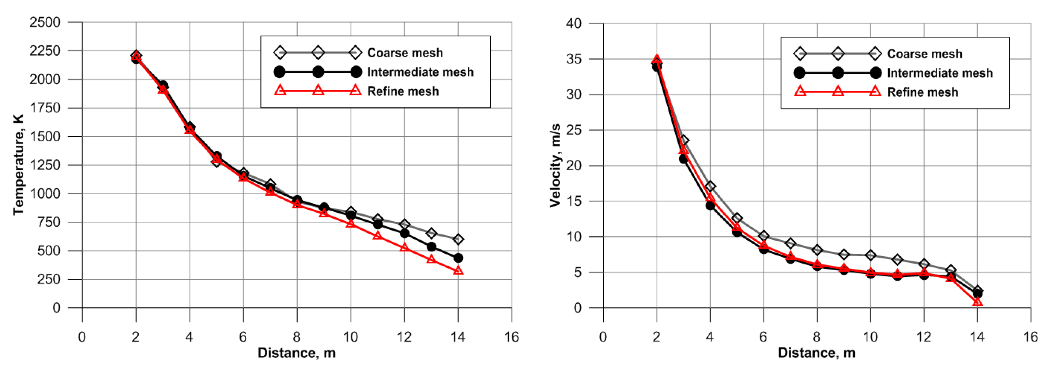
4.1. Grid Independence
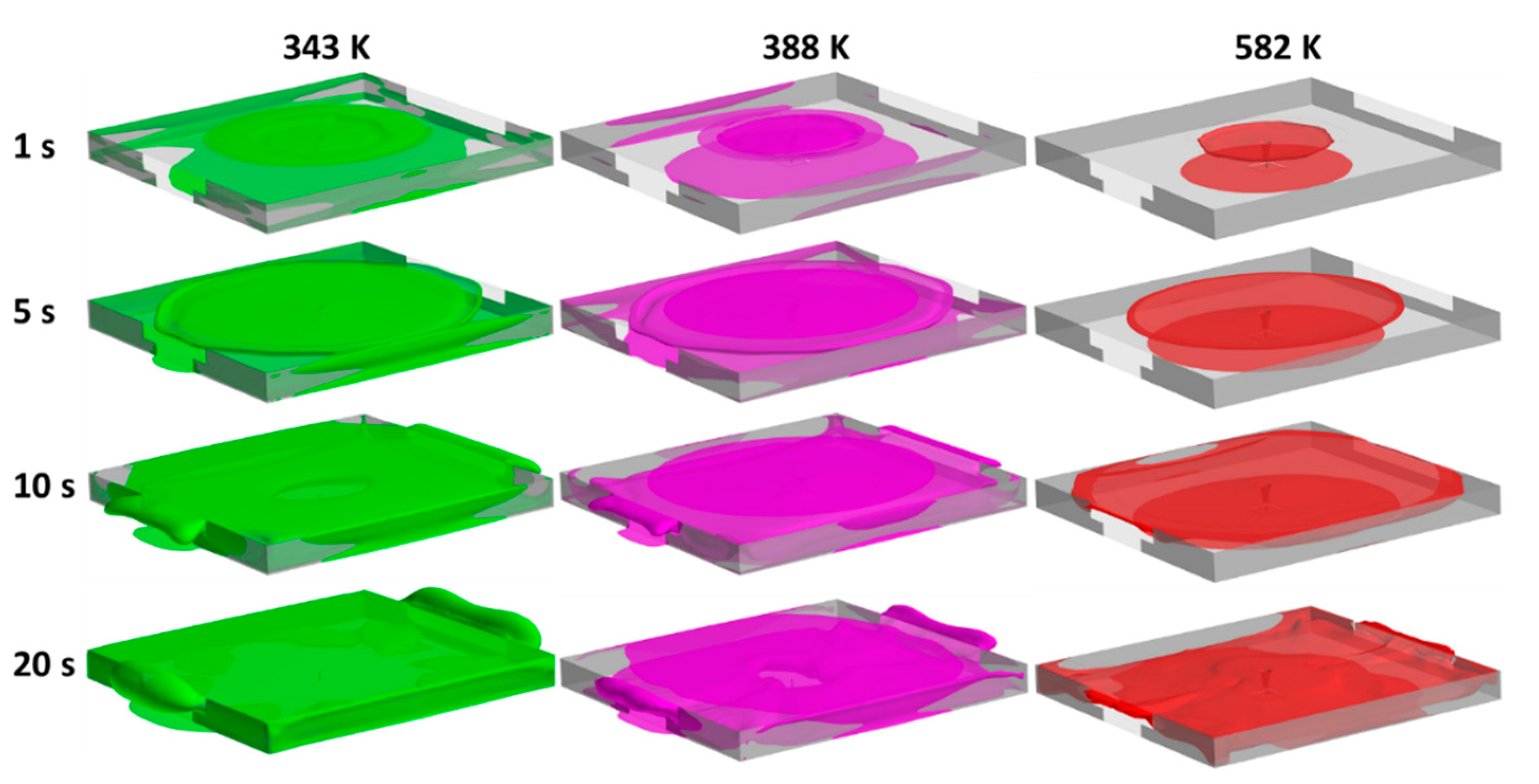
To comply with the CFD model evaluation protocol [26], three different grids, were simulated (coarse, intermediate, and refined) as presented in Table 2.
Case 1 (Table 1) with a constant mass flow rate upward release in the covered car park through TPRD = 3.34 mm was selected for grid independence study. At each refinement step the average length of the computational cells was halved inside the car park. Attention was paid in areas where high gradients and complex phenomena were expected for example, at the leak point, and the ceiling as recommended by Baraldi et al. [27]. Temperature and velocity were measured at points under the car park ceiling at 1% of the height from the nozzle exit to the ceiling, H, at an increasing radius from the jet axis at a flow time of 5.5 s. The temperature and velocity results are shown in Figure 3. It can be seen that mesh resolution does not affect the results at the points close to the jet axis for temperature although a difference is evident for points, further from the axis, closer to the car park walls, in this region the gird is coarser with cells in the region of 20–30 cm lengthwise. However, the height of the cells is constant with distance from the jet axis to ensure the points at a distance of 1% H are captured.
In the vicinity of the car park walls, the temperature differs by a factor of 2 between meshes, with the temperature predicted using a coarse grid twice that predicted by the refined mesh. The difference was most pronounced at this position. In terms of velocity prediction, higher values were predicted by the coarser mesh with little difference observed for the two more refined meshes. Both coarse and intermediate meshes were used in this study depending on the area of interest due to the computational expense of the refined mesh. The differences in temperature and velocity prediction in the regions of most interest were deemed minor compared to the difference in computational time (1 week versus 7 weeks for 5 s on a 64 cores machine).
It should be noted that the CFL number in this study did not exceed 40. It was found in previous related studies by the authors [7,10,11] that there is no adverse effect on the release and dispersion, provided the CFL number is 1 or less for the initial stage (here, CFL number was kept below 1 for the first 1 s of the release). The initial simulation results also confirmed that there are no changes in the result if a CFL number of 40 is used for the large-scale car park simulation after the first 1 s of flow time.

4.2. Upward Release

One possible direction of hydrogen release is upward from the ceiling of the car. In an outdoor environment, this may be advantageous. However, an upward ignited release in an enclosure will potentially lead to flame impingement and development of a layer of hot gas under the ceiling. Five upward release scenarios were simulated here through TPRD diameters of 0.5 mm, 2 mm, and 3.34 mm. These five numerical tests are: three cases without a car body (Case 1, 2 and 7 in Table 1) and two cases with a car geometry included (Case 3 and 8 in Table 1).

4.2.1. Constant Mass Flow Rate Release

A constant mass flow rate hydrogen release of 299.3 g/s through TPRD = 3.34 mm was simulated as a starting point for case 1 only. Whilst it is recognised that it is more realistic to account for blowdown, releases through a TPRD of this diameter have been previously studied by the authors [10], providing a point for comparison. Known TPRD diameters can range from 2 mm to 5 mm depending on the manufacturer and 3.34 mm was taken as the largest diameter in this study. This case represents the worst-case scenario here since tank blowdown is not accounted for, care should be taken in interpreting the results as they represent a continuous leak. However, accumulation of the hot gas can be observed within the initial seconds of the release, before the tank pressure would have dropped to a significant level. A constant release can also be useful in understanding what may occur in other scenarios where pipes and tanks may leak for a longer period.
Three levels of temperatures related to three harm criteria and visible flame representative temperature (1573 K) were considered in this study for the first 20 s of the release, which is thought to be the crucial initial stage that can be used to estimate the hazard distances. It should be noted that Figure 4 and Figure 5b show 3D iso-surfaces of the hot gases, i.e., the surface in the domain at that specific temperature, whereas the complete temperature distribution can be seen in Figure 5a which gives an indication of the hot jet development. It can be seen from Figure 4 and Figure 5b that the hot gas at no-harm criterion temperature (343 K) occupied the entire car park in just 10 s and 3 m outside the vent in 20 s. The hot gas at fatality criterion temperature covered the ceiling and accumulated on the upper half layer (1.3 m height to the ceiling) of the enclosure.
For the constant upward hydrogen release any extraction vents of mechanical ventilation system would be covered by combustion products with a temperature greater than 300 °C within 10 s.

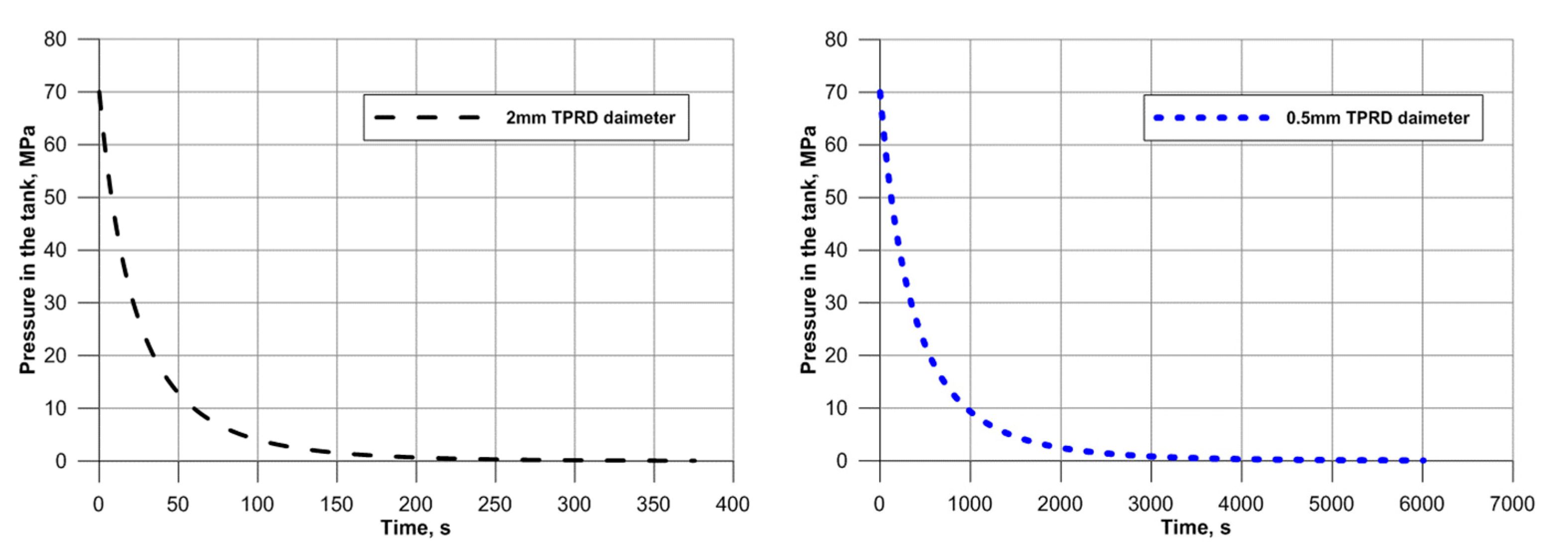
4.2.2. Tank Blowdown

A Tank blowdown was considered as described in Section 3 to simulate realistic upward hydrogen releases for two release diameters as follows.

Upward 2 mm TPRD Diameter Release

One of the possible safety solutions to avoid the catastrophic release in case 1 (TPRD = 3.34 mm) is to decrease the TPRD diameter. Thus, TPRD = 2 mm was used to simulate case 2 without a car and case 3 with car body geometry. The main difference between these two cases was the distance between the release and the ceiling, in addition to the inclusion of the car geometry within the car park. In case 2 (no car) the leak was located 2.1 m from the ceiling, and in case 3 (with a car) the leak was located 1.13 m from the ceiling.
The results for case 2 (no car) can be seen in Figure 6 (far right). It is shown that the extent of the hot gas at fatality temperatures is a maximum at a release time of only 10 s and the hot envelope reduces in 20 s with covering only a 7 m radial diameter from the jet axis on the top layer of the enclosure close to the ceiling. Case 3 with car body geometry was also simulated as shown in Figure 6 and Figure 7. The extent of the hot cloud corresponding to “no harm” and “pain limit” temperatures was similar to case 2 (not shown here) despite a reduction in the distance between the release point and the car park ceiling (from 2.1 m in case 2 to 1.13 m in case 3). The maximum envelope of hot products at 582 K occurred in less than 5 s, and decreased to a similar level of the case with no car within 20 s. The comparison between cases 2 and 3 showed that for an upward release the inclusion of a car geometry had minimal impact on the prediction of hot envelope development under the car park ceiling. The car does not obstruct the flow of combustion products as is evident in downward release scenarios. It should be noted that the numerical simulations predicted a temperature rise on the floor, car park walls and some exposed car body due to the effect of radiation heat transfer as considered in this study. It is also emphasised that the images in Figure 6 are iso-surfaces and do not show the higher temperatures within the jet (e.g., as shown in Figure 5a).

Upward 0.5 mm TPRD Diameter Release

To further reduce the hazard and associated risk, two upward releases through a TPRD with a diameter of 0.5 mm were simulated. Case 7 did not include the car geometry; hence the leak was 2.1 m from the car park ceiling. Case 8 included the car geometry, and the leak position was 1.13 m from the car park ceiling. The results for case 7 are shown in Figure 8, it can be seen that the hot gas envelope at 582 K extends over a very small area immediately above the release, under the car park ceiling, with a diameter of 1.5 m. The extent of the cloud of gas at 582 K reaches a maximum within the just 1 s of the release and remains constant until 20 s, after which point the simulation was terminated. The hot products at 388 K cover a wider area under the car park, extending a radius of 9 m away from the jet axis. The gas at a no-harm temperature extends over a significantly reduced area when compared with the releases from the TPRD diameters of 2 mm and 3.34 mm discussed previously. Indeed, gases at this temperature are evident only immediately above the leak and in a later along the ceiling.
An upward release through TPRD = 0.5 mm from the car body (case 8) is presented in Figure 9. As noted, this case is similar to case 7 but with the inclusion of the car body and a higher release point. The area under the ceiling, covered by the hot gas at a temperature of 582 K increased compared to case 7. However, the leak point is closer to the ceiling, and the cloud at 582 K reached a maximum within 5 s and decreases to a radial distance of 2 m under the ceiling from the jet axis. It should be noted that this case, i.e., TPRD = 0.5 mm, is inherently the safest case scenario investigated here for an upward release as could be expected.

4.3. Downward Release

In this section, downward ignited hydrogen releases from TPRD of onboard storage in a naturally ventilated covered car park are described. Releases through two TPRD diameters, 0.5 mm and 2 mm at angles of 0°, 30° and 45° to the vertical were simulated and compared. All downward release simulations include car geometry.

4.3.1. 0° Release Angle with the Vertical Axis

Straight downward releases from onboard storage in a hydrogen-powered vehicle have been covered in the literature for an open atmosphere condition. Li et al. [28] studied a vertically downward unignited and ignited release from TPRD = 4.2 mm under a car for both 35 MPa and 70 MPa storage pressure in an open environment. The hazard distances for both unignited and ignited hydrogen releases with vertically downward direction were found to be shorter than for free jets. The hazard distance was noted as at least 12 m for a 70 MPa release. However, Li et al. [28] focused on releases in an open atmosphere without confinement and a relatively big TPRD diameter compared to this study. In recent work by Li and Luo [29], the same release diameters and conditions for ignited hydrogen were compared with CNG (methane) releases, and it was found that the CNG jet fire duration was twice that of the hydrogen jet fire. Their study was also in the open atmosphere without any obstructions.
Vertically downward ignited hydrogen releases through TPRD = 2 mm (case 4) and TPRD = 0.5 mm (case 9) were simulated. The downward release from TPRD = 2 mm is shown in Figure 10. It can be seen how the car body and vertical downward direction of the release played an important role in decreasing the extent of the hot cloud at the fatality limit temperature. The hot cloud at 582 K reached a maximum extent within 5 s of the release decreased to a limited area above the car, as shown in Figure 10 and Figure 11. However, the gas at 343 K (no-harm limit) and 388 K (pain limit) spread out within the car park, covering the upper layer with potential consequences for public safety.
The downward release from TPRD = 0.5 mm is shown in Figure 11 and Figure 12. It can be seen how the extent of the area covered by hot gas at no-harm, pain and fatality temperatures has decreased considerably compared to downward release from TPRD = 2 mm (case 4) and, what should be emphasised, compared to the upward release cases (case 7 and 8) for the same TPRD diameter. Much of the heat transfer occurred due to radiation which resulted in a rise in the temperature of the walls and the floor area.
Blockage of a passenger escape route was one of the potential safety issues noted with a vertical downward release as is evident from Figure 11 and Figure 12. It can be seen how the presence of a visible flame (1573 K) may block access to both rear doors for a downward release from TPRD = 2 mm and left-hand rear door for a downward release from TPRD = 0.5 mm. Hot gasses at 582 K completely obstruct the driver and passenger escape routes from the car. Thus, downward hydrogen release at an angle to the vertical was considered to address this safety concern and is presented in the following section.

4.3.2. 30° Release Angle with the Vertical Axis

As noted, a vertically downward release may potentially block passenger escape routes from the car. A 30° release angle with the vertical was considered to overcome this safety concern. Releases from TPRD = 2 mm (case 5) and TPRD = 0.5 mm (case 10) were simulated. The results for TPRD = 2 mm are shown in Figure 13 and Figure 14. The release was simulated in the centre of the car park with an angle orientated to the back of the car, which led to flow towards the back vent of the car park causing hot gas concentrated at the rear to then propagate to the front of the car park. Similar to the previous cases with TPRD = 2 mm, the combustion products at no-harm and pain temperature limits formed a layer under the ceiling although it can be seen mostly towards the back of the car park in this case. The hot products at 582 K were concentrated in a tail-like envelope towards the back of the car and extended to a distance of approximately 5.5 m long beginning to rise and form a layer due to buoyancy. The maximum flame occurred within just 1 s, it was attached to the floor and also extended around 5.5 m from the car. The visible flame length decreased by 25% of its maximum length by 20 s.
Results from a 30° angle downward release from TPRD = 0.5 mm (case 10) are shown in Figure 15 and compared with case 5 in Figure 13. It can be noticed that the gas products at no-harm temperature covered a much smaller volume of the car park at the back of the car while a flame existed only 1 m away from the back of the car attached to the floor. The cloud of hot gas at 388 K reached a maximum volume in 10 s while the hot cloud at 582 K reached a maximum extent at 5 s and remained until 20 s, reaching 2.5 m from the back of the car. It has to be noted that there is no blockage of the passenger escape routes in cases 5 and 10 with a 30° angle downward release compared with the vertical downward releases in cases 4 and 9.

4.3.3. 45° Release Angle with the Vertical Axis

A final downward release angle of 45° with the vertical axis was simulated for releases from TPRD = 2 mm and TPRD = 0.5 mm. The results of case 6 (TPRD = 2 mm) are shown in Figure 16 and Figure 17. The behaviour of the hot gas at no-harm and pain limit temperatures is similar to the 30° angle downward release considered previously, with hot gas accumulating to the back of the car and moving to the front of car park in 20 s. Since the angle 45° provided a further push to the back rather than down compared to angle 30°, the hot gas presented more in the backside of the car park. The hot products at 582 K and flame extended further back from the car to a distance of around 6.5 m in just 1 s. This distance is about 1 m longer than the one predicted in case 6 (angle 30°, TPRD = 2 mm). The flame started to decrease with tank blowdown and reduce almost 10% by a time of 20 s.
The results of case 11 with TPRD = 0.5 mm and 45° angle with the vertical, are presented in Figure 17 and Figure 18. The gas products at 343 K are similar to case 10 (30° angle and TPRD = 0.5 mm). The hot gas at 388 K and 582 K reached the maximum coverage volume in the car park in just 5 s and both extended in the back of the car by 3 to 3.5 m. The flame attached to the floor surface like the 30° angle downward release. The visible flame length was approximately 1.5 m to the back of the car, slightly longer than 30° angle downward release.

4.3.4. Comparison of Release Angles

Iso-surfaces of temperature at a release time of 20 s are compared for all TPRD = 2 mm and TPRD = 0.5 mm cases which include the car body in Figure 19. The hydrogen jet fire from TPRD = 2 mm led to the upper layer of the car park upper being covered with a hot gas at 388 K for all release directions considered, i.e., upward and downward with 0°, 30° and 45° angles. The hot products at 582 K for this TPRD diameter covered the top layer close to the ceiling with a radial distance of 5 m in the case of an upward release. The car body and the floor surface were heated up due to the radiative heat transfer from the upward release flame, this might become a safety issue for people and unprotected first responders. The vertically downward release (0° angle with the vertical axis) spread out from three sides of the car, as the release occurred close to the back of the car. The hot gas at 582 K to the left and right sides of the car might block passenger escape routes. From the 30° and 45° angle comparison, it can be seen that the downward release at an angle appears to be safer in this sense compared to the vertically downward case as there is no hot gas at 582 K in the vicinity of the sides of the car, rather it is directed away in a “tail” from the back. The release angle of 30° lead to jet at a temperature of 582 K around 5.5 m away from the car, 1 m less than that predicted in the case of a 45° release angle. The flame, as it is considered as a lethal threshold, was dangerous when the release was vertically downward, and blocked doors, whereas a release angle of 30° and 45° lead to a jet flame from the back of the car.
Decreasing the TPRD diameter to an order of 0.5 mm is proposed from a safety perspective of a hydrogen vehicle in covered park if a tank-TPRD system can withstand a fire. The extent of the cloud of hot products at 388 K decreased significantly compared to TPRD = 2 mm and it was limited only to a very small envelope above the release and the floor surface around the car due to the radiation in terms of upward release while it spread around the three sides of the car for vertically downward release. The downward release with 30° and 45° angles led to a comparably smaller volume of hot gas to the back of the car. Similarly, the maximum cloud of hot products at 588 K was reduced considerably when compared to the 2 mm diameter release. However, the vertically downward release still obstructed passenger escape routes from the vehicle. The angle 30° and 45° releases decreased the fatality temperature hazard distance from the back of the car to just 2.5 m and 3.25 m respectively. The hydrogen flame was noticed only in a very limited area although remained problematic in case of vertically downward release as passenger escape routes were blocked.
Considering all the simulations from a mechanical ventilation perspective, it was previously noted that based on [15] the extent of the cloud of hot gasses at 300 °C could be used as the temperature limit that can be recorded at ventilation ducts for inherently safer operation of a ventilation system in the event of a hydrogen jet fire. The downward direction of the release significantly contributed to the decrease of temperature for the ventilation system. Whilst the ceiling is reached for TPRD = 2 mm for jet inclinations of either 0°, 30° or 45°, a TPRD = 0.5 mm and jet inclination of 45° did not produce a cloud of hot products at the ceiling that could jeopardise the mechanical ventilation system during the tank blowdown duration.

5. Conclusions

Numerical experiments with ignited hydrogen releases from TPRD of onboard storage of hydrogen-powered vehicles in a naturally ventilated covered car park have been performed for the first time. Hydrogen jet fires from TPRD were investigated in a car park with dimensions L × W × H = 30 × 28.6 × 2.6 m incorporating two vents which provided an opening equivalent in area to 5% of the floor area across two opposing walls following British Standard BS 7346-7:2013. Eleven cases were simulated to evaluate the effect of different TPRD diameters and release directions. A hydrogen blowdown model was applied to reproduce realistic conditions of onboard storage tank emptying. Three TPRD diameters of 3.34 mm, 2 mm and 0.5 mm were studied. Thermal effects were evaluated against harm criteria based on no-harm (343 K), pain (388 K) and fatality (582 K) temperature limits. Four TPRD release directions were compared for TPRD = 2 mm and TPRD = 0.5 mm, including one vertically upward, and three downward at angles 0°, 30° and 45° with the vertical axis. The vertically downward release could potentially make it difficult for passengers to escape through car doors for both TPRD = 0.5 mm and TPRD = 2 mm cases. The upward release from TPRD = 2 mm warmed the car body and floor surface above 582 K within just 20 s due to radiation heat transfer from the flame and combustion products. It was found that the downward release with an angle of 30° and 45° with the vertical axis is inherently safer for TPRD = 0.5 mm compared to TPRD = 2 mm. Therefore, it can be suggested that innovative TPRD designs of smaller diameter should be investigated further experimentally to confirm the revealed by computational hydrogen safety engineering decrease of hazard distances and allow inherently safer parking of hydrogen vehicles in covered and underground structures without the introduction of new hazards and associated risks. Based on this study it is recommended that TPRD diameter is reduced to a fraction of millimetre and releases are at an angle vertically downward if hydrogen vehicles are being used in a covered and underground car parking.

Author Contributions

Problem formulation: H.H., S.B. and V.M.; methodology: H.H. and S.B.; software: H.H.; formal analysis: H.H., S.B. and V.M.; writing—original draft preparation: H.H. and S.B.; writing—review and editing, H.H., S.B. and V.M.; supervision: S.B. and V.M. All authors have read and agreed to the published version of the manuscript.

Funding

The authors are grateful to the Fuel Cells and Hydrogen 2 Joint Undertaking for funding this research through both the HyResponder project “European Train the Trainer programme for Responders” under Grant Agreement No. 875089 and the HyTunnel-CS project “Pre-normative research for safety of hydrogen driven vehicles and transport through tunnels and similar confined spaces” under grant agreement No. 826193. This Joint Undertaking receives support from the European Union’s Horizon 2020 Research and Innovation programme, Hydrogen Europe and Hydrogen Europe Research.

Conflicts of Interest

The authors declare no conflict of interest.

References

  1. European Parliament. Regulation C. No 406/2010 of 26 April 2010 Implementing Regulation (EC) No 79/2009 of the European Parliament and of the Council on Type-Approval of Hydrogen-Powered Motor Vehicles; European Parliament: Brussels, Belgium, 2010. [Google Scholar]
  2. Fuster, B.; Houssin-Agbomson, D.; Jallais, S.; Vyazmina, E.; Dang-Nhu, G.; Bernard-Michel, G.; Kuznetsov, M.; Molkov, V.; Chernyavskiy, B.; Shentsov, V.; et al. Guidelines and recommendations for indoor use of fuel cells and hydrogen systems. Int. J. Hydrogen Energy 2017, 42, 7600–7607. [Google Scholar] [CrossRef] [Green Version]
  3. HyTunnel-CS Project Website. Available online: https://hytunnel.net/ (accessed on 7 August 2021).
  4. Brennan, S.; Molkov, V. Pressure peaking phenomenon for indoor hydrogen releases. Int. J. Hydrogen Energy 2018, 43, 18530–18541. [Google Scholar] [CrossRef]
  5. Brennan, S.; Molkov, V. Safety assessment of unignited hydrogen discharge from onboard storage in garages with low levels of natural ventilation. Int. J. Hydrogen Energy 2013, 38, 8159–8166. [Google Scholar] [CrossRef]
  6. Makarov, D.; Shentsov, V.; Kuznetsov, M.; Molkov, V. Pressure peaking phenomenon: Model validation against unignited release and jet fire experiments. Int. J. Hydrogen Energy 2018, 43, 9454–9469. [Google Scholar] [CrossRef]
  7. Hussein, H.; Brennan, S.; Molkov, V. Dispersion of hydrogen release in a naturally ventilated covered car park. Int. J. Hydrogen Energy 2020, 45, 23882–23897. [Google Scholar] [CrossRef]
  8. Xu, B.; Wen, J. Numerical study of spontaneous ignition in pressurized hydrogen release through a length of tube with local contraction. Int. J. Hydrogen Energy 2012, 37, 17571–17579. [Google Scholar] [CrossRef]
  9. SAE International. SAE J2578, Technical Information Report for Fuel Systems in Fuel Cell and Other Hydrogen Vehicles; A Surface Vehicle Information Report; SAE International: Warrendale, PA, USA, 2009. [Google Scholar]
  10. Brennan, S.; Hussein, H.; Makarov, D.; Shentsov, V.; Molkov, V. Pressure effects of an ignited release from onboard storage in a garage with a single vent. Int. J. Hydrogen Energy 2019, 44, 8927–8934. [Google Scholar] [CrossRef]
  11. Hussein, H.; Brennan, S.; Shentsov, V.; Makarov, D.; Molkov, V. Numerical validation of pressure peaking from an ignited hydrogen release in a laboratory-scale enclosure and application to a garage scenario. Int. J. Hydrogen Energy 2018, 43, 17954–17968. [Google Scholar] [CrossRef]
  12. TI Organization for Standardization. 19880-1 I. Gaseous Hydrogen—Fuelling Stations, Part 1: General Requirements; TI Organization for Standardization: Dallas, TX, USA, 2018. [Google Scholar]
  13. National Fire Protection Association (NFPA). Hydrogen Technologies Code; National Fire Protection Association (NFPA): Quincy, MA, USA, 2011. [Google Scholar]
  14. International Electrotechnical Commission. IEC 60079-10-1. Explosive Atmospheres—Part 10-1: Classification of Areas—Ex-Plosive Gas Atmospheres; International Electrotechnical Commission: London, UK, 2015. [Google Scholar]
  15. BSI. BS 7346-7:2013. Components for Smoke and Heat Control Systems—Part 7: Code of Practice on Functional Recommendations and Calculation Methods for Smoke and Heat Control Systems for Covered Car Parks; BSI: London, UK, 2013. [Google Scholar]
  16. Chow, W. On safety systems for underground car parks. Tunn. Undergr. Space Technol. 1998, 13, 281–287. [Google Scholar] [CrossRef]
  17. Van Der Heijden, M.G.M.; Loomans, M.G.L.C.; Lemaire, A.D.; Hensen, J. Fire safety assessment of semi-open car parks based on validated CFD simulations. Build. Simul. 2013, 6, 385–394. [Google Scholar] [CrossRef] [Green Version]
  18. Zhang, X.; Guo, Y.; Chan, C.; Lin, W. Numerical simulations on fire spread and smoke movement in an underground car park. Build. Environ. 2007, 42, 3466–3475. [Google Scholar] [CrossRef]
  19. NEN. 2443 NEN-IN. Parkeren en Stallen van Personenauto’s op Terreinen en Garages; NEN: Delft, The Netherlands, 2000. [Google Scholar]
  20. Molkov, V.; Makarov, D.; Bragin, M. Physics and Modelling of Underexpanded Jets and Hydrogen Dispersion in Atmosphere; Russian Academy of Sciences: Moscow, Russia, 2009. [Google Scholar]
  21. Molkov, V. Fundamentals of Hydrogen Safety Engineering I. 2012. Available online: www.bookboon.com (accessed on 7 August 2021).
  22. ANSYS, Inc. ANSYS Fluent R16.2 User Guide; ANSYS, Inc.: Canonsburg, PA, USA, 2016. [Google Scholar]
  23. Yan, L.; Yue, G.; He, B. Development of an absorption coefficient calculation method potential for combustion and gasification simulations. Int. J. Heat Mass Transf. 2015, 91, 1069–1077. [Google Scholar] [CrossRef]
  24. Cirrone, D.; Makarov, D.; Molkov, V. Thermal radiation from cryogenic hydrogen jet fires. Int. J. Hydrogen Energy 2019, 44, 8874–8885. [Google Scholar] [CrossRef]
  25. Roberts, P.T.; Shirvill, L.C.; Roberts, T.A.; Butler, C.J.; Royle, M. Dispersion of hydrogen from high-pressure sources. Inst. Chem. Eng. Symp. Ser. 2006, 151, 410. [Google Scholar]
  26. Baraldi, D.; Melideo, D.; Kotchourko, A.; Ren, K.; Yanez, J.; Jedicke, O. SUSANA Final Report D6.2, The CFD Model Evaluation Protocol; 2016; Available online: https://www.h2fc-net.eu/collaboration/susana-database/susana-public-documents/ (accessed on 10 August 2021).
  27. Baraldi, D.; Melideo, D.; Kotchourko, A.; Ren, K.; Yanez, J.; Jedicke, O.; Giannissi, S.; Tolias, I.; Venetsanos, A.; Keenan, J.; et al. Development of a model evaluation protocol for CFD analysis of hydrogen safety issues the SUSANA project. Int. J. Hydrogen Energy 2017, 42, 7633–7643. [Google Scholar] [CrossRef]
  28. Li, Z.Y.; Makarov, D.; Keenan, J.; Molkov, V. CFD study of the unignited and ignited hydrogen releases from TPRD under a fuel cell car. In Proceedings of the International Conference on Hydrogen Safety, Yokohoma, Japan, 19 October 2015. [Google Scholar]
  29. Li, Z.; Luo, Y. Comparisons of hazard distances and accident durations between hydrogen vehicles and CNG vehicles. Int. J. Hydrogen Energy 2018, 44, 8954–8959. [Google Scholar] [CrossRef]
Figure 1. Sketch of the naturally ventilated covered car park with car geometry.
Hydrogen 02 00018 g001
Figure 2. Pressure dynamics for adiabatic blowdown from 70 MPa, 117 L tank for 2 mm (left) and 0.5 mm diameter TPRD (right).
Hydrogen 02 00018 g002
Figure 3. Temperature (left) and velocity (right) along with the ceiling, for varying mesh resolutions in the covered car park, with a 299.3 g/s hydrogen release through TPRD = 3.34 mm (case 1) at flow time 5.5 s.
Hydrogen 02 00018 g003
Figure 4. Iso-surfaces showing no-harm (left), pain limit (centre) and fatality temperature (right) for ignited hydrogen release in case 1 (TPRD = 3.34 mm, constant upward release from distance 2.1 m to the ceiling, no car body).
Hydrogen 02 00018 g004
Figure 5. (a) Temperature contours along the central plane of the covered car park for case 1. (b) Side view iso-surfaces showing pain limit (top), fatality limit (middle) and flame temperature (bottom) for case 1 (TPRD = 3.34 mm, constant upward release from distance 2.1 m to the ceiling, no car body) at time 20 s.
Hydrogen 02 00018 g005
Figure 6. Iso-surfaces showing no-harm (343 K), pain limit (388 k) and fatality limit temperature (582 k) for ignited hydrogen release in case 3 (TPRD = 2 mm, upward release from distance 1.13 m from the ceiling with tank blowdown and car body) and case 2 (TPRD = 2 mm, upward release from distance 2.1 m to the ceiling with tank blowdown, no car body).
Hydrogen 02 00018 g006
Figure 7. Side view iso-surfaces showing pain limit (388 K), fatality limit (582 K), and flame visible (1573 K) temperatures. (Left): case 3 (TPRD = 2 mm, upward release with tank blowdown from distance 1.13 m to the ceiling). (Right): case 8 (TPRD = 0.5 mm, upward release with tank blowdown from distance 1.13 m to the ceiling).
Hydrogen 02 00018 g007
Figure 8. Iso-surfaces showing no-harm (343 K), pain limit (388 K) and fatality limit (582 K) temperature for ignited hydrogen release in case 7 (TPRD = 0.5 mm, upward release with tank blowdown from distance 2.1 m to the ceiling, no car body).
Hydrogen 02 00018 g008
Figure 9. Iso-surface showing no-harm (343 K), pain limit (388 K) and fatal limit (582 K) temperature for ignited hydrogen release in case 8 (TPRD = 0.5 mm, upward release with tank blowdown from distance 1.13 m to the ceiling, and car body).
Hydrogen 02 00018 g009
Figure 10. Iso-surfaces showing no-harm (343 K), pain (388 K) and fatality (582 K) limit temperatures for ignited hydrogen release in case 4 (TPRD = 2 mm, 0° angle downward release with tank blowdown and car body).
Hydrogen 02 00018 g010
Figure 11. Side view iso-surface showing pain (388 K), fatality (582 K) limits and visible flame temperature (1573 K) for case 4 with TPRD = 2 mm (left) and case 9 with TPRD = 0.5 mm (right).
Hydrogen 02 00018 g011
Figure 12. Iso-surfaces showing no-harm (343 K), pain (388 K) and fatality (582 K) temperature limits for ignited hydrogen release in case 9 (TPRD = 0.5 mm, 0° angle downward release with tank blowdown and car body).
Hydrogen 02 00018 g012
Figure 13. Iso-surfaces showing no-harm (343 K), pain (388 K), fatality (582) limits and visible flame temperature (1573 K) for ignited hydrogen release in case 5 (TPRD = 2 mm, 30°angle downward release with tank blowdown and car body).
Hydrogen 02 00018 g013
Figure 14. Side view iso-surfaces showing pain (388 K), fatality (582 K) limits and visible flame temperature (1573 K) for case 5 with TPRD = 2 mm (left), and case 10 with TPRD = 0.5 mm (right).
Hydrogen 02 00018 g014
Figure 15. Iso-surfaces showing no-harm (343 K), pain (388 K), fatality (582 K) temperature limits and visible flame temperature (1573 K) for ignited hydrogen release in case 5 (TPRD = 0.5 mm, 30° angle downward release with tank blowdown and car body).
Hydrogen 02 00018 g015
Figure 16. Iso-surfaces showing no-harm (343 K), pain (388 K), fatality (582 K) limits and visible flame temperature (1573 K) for ignited hydrogen release in case 6 (TPRD = 2 mm, 45° angle downward release with tank blowdown and car body).
Hydrogen 02 00018 g016
Figure 17. Side view iso-surfaces showing pain (388 K), fatality (582 K) temperature limits and visible flame temperature (1573 K) for case 6 with TPRD = 2 mm (left) and case 11 with TPRD = 0.5 mm (right).
Hydrogen 02 00018 g017
Figure 18. Iso-surfaces showing no-harm (343 K), pain (388 K) and fatality (582 K) limits and visible flame temperature (1573 K) for ignited hydrogen release in case 11 (TPRD = 0.5 mm, 45° angle downward release with tank blowdown and car body).
Hydrogen 02 00018 g018
Figure 19. Side view iso-surfaces showing pain (388 K) and fatality (582 K) temperature limits and visible flame temperature (1573 K) for release time 20 s. (Left) TPRD = 2 mm, “Upward”—case 3; downward at 0°—case 4, 30°—case 5, 45°—case 6). (Right) TPRD = 0.5 mm, “Upward”—case 8; downward at 0°—case 9, 30°case 10, 45°—case 11).
Hydrogen 02 00018 g019
Table 1. Numerical experiments considered for a covered car park with natural ventilation.
Case NumberTPRD Diameter (Notional) mmRelease DirectionRelease Angle with Vertical Car Geometry Blow-Down ModelInitial H2 Rate kg/sRelease Distance Ceiling, m
Case 13.34 (56.4)UpwardNoNo0.29932.1
Case 22 (33.8)UpwardNoYes0.10722.1
Case 32 (33.8)UpwardYesYes0.10721.13
Case 42 (33.8)DownwardYesYes0.10722.35
Case 52 (33.8)Downward30°YesYes0.10722.35
Case 62 (33.8)Downward45°YesYes0.10722.35
Case 70.5 (8.44)UpwardNoYes0.00672.1
Case 80.5 (8.44)UpwardYesYes0.00671.13
Case 90.5 (8.44)DownwardYesYes0.00672.35
Case 100.5 (8.44)Downward30°YesYes0.00672.35
Case 110.5 (8.44)Downward45°YesYes0.00672.35
Table 2. Mesh details for grid independence study.
MeshNo. of CellsNo. of FacesNo. of NodesCells at Leak
Coarse691,7592,297,390745,416one
Intermediate1,013,4493,293,8091,072,606one
Refine2,656,2448,402,2472,758,610four
Publisher’s Note: MDPI stays neutral with regard to jurisdictional claims in published maps and institutional affiliations.

