Article

Development of an Airbag Geometry Specific for Autonomous Vehicles

by
Bartolomeu Franco
1,2,
José Manuel Alves Ribeiro
1,3 and
Isidro de Jesús Sánchez-Arce
1,4,*
1
Departamento de Engenharia Mecânica, Escola de Ciências e Tecnologia, Universidade de Trás-os-Montes e Alto Douro (UTAD), Quinta de Prados, 5000-801 Vila Real, Portugal
2
ZF Friedrichshafen AG Portugal, Parque Industrial da Gemeira, Rua da Barreira 1237, 4990-645 Ponte de Lima, Portugal
3
Centre for the Research and Technology of Agro-Environmental and Biological Sciences (CITAB), Quinta de Prados, 5000-801 Vila Real, Portugal
4
Laboratório Associado de Energia, Transportes e Aeronáutica (LAETA-INEGI), Rua Dr. Roberto Frias 400, Polo da FEUP, 4200-465 Porto, Portugal
*
Author to whom correspondence should be addressed.
Eng 2023, 4(4), 2553-2570; https://doi.org/10.3390/eng4040146
Submission received: 10 August 2023 / Revised: 24 September 2023 / Accepted: 9 October 2023 / Published: 11 October 2023
(This article belongs to the Special Issue Feature Papers in Eng 2023)

Abstract

:
Airbags are important safety devices in modern vehicles. However, their effectiveness is linked to the occupants being seated in standard positions. Although autonomous vehicles are less accident-prone, they are also equipped with airbags, similar to any other vehicle. Additionally, autonomous vehicles allow for occupants seated in non-standard positions, so in the case of a collision, the airbags’ effectiveness decreases. In this work, an airbag design suitable for both assisted and autonomous driving conditions is proposed, the driver’s airbag being the object of interest. Airbag geometry, threads, seam strength, and seam geometries were selected following Design of Experiments (DoE) methodologies and a series of experimental tests. Moreover, an adaptive system based on sewn tethers allows the airbag to adapt to the driving mode, which is proposed and validated. Finally, all the findings were experimentally tested on two different geometries. The results were satisfactory as the deployed airbag shape and dimensions were as expected, indicating that this airbag design is capable of protecting the driver of a vehicle capable of autonomous driving.

1. Introduction

Airbags are important safety devices in the case of vehicle collision, having contributed to saving numerous lives [1,2]. The airbag system is composed of several components, the most important being the inflatable cushions (the airbag itself), impact sensors, ignition system, propellant, mounting hardware, and the moulded covers Nayak et al. [3]. From this list, it can be seen that the inflatable cushions, the ignition system, and the propellant are the most critical components to ensure the correct deployment of the airbag. Airbags could be installed in different parts of the vehicle, the most common are as follows: (a) driver’s airbag; (b) front passenger airbag; and (c) side airbags, which includes curtain and thorax (seat) airbags. The driver and passenger airbags are mandatory for all US vehicles produced after 1998 [4].
Vehicle safety regulations directly impact the design and testing of new airbags [4] because the required tests dictate parameters such as the deployment time. For example, in 1997 in the U.S., the regulations changed the testing method from a barrier to a sledge, both at 48 km/h. This change led to using different airbag designs on vehicle models after 1998. Braver et al. [4] analysed crash and fatalities data for models from 1997 and models from 1998 to 1999. In this case, vehicles of the same make, models, and platforms were analysed (a pool of 171 makes and models). In fact, the change in airbag design (and regulation) led to a 7% reduction in fatalities and airbag-induced injuries despite the yearly increase in travelled distance. In addition, the death risk in a frontal crash for children (0–4 years old) as front seat passengers was reduced up to 65% [5]. On the other hand, the airbags developed after this regulatory change also possess features such as dual-stage inflators and a series of sensors to identify the presence and size of the occupant [5], so these features may have also contributed to the fatality and injury reduction observed. The advances in technology also bring updates in the regulations, resulting in further airbag improvements, which are accompanied by further sensors [6]; therefore, impacting positively the mortality reduction with respect to the previous airbag generations [6].
The aforementioned studies are based on the standard driving position. However, alterations to this position, e.g., being farther away from the knee bolster or highly reclined seat can lead to a phenomenon known as ‘submarining’ where the occupant slides down the seat belt, resulting in further injuries. Small occupants are more likely to experience submarining [7,8]. These non-standard seating positions are more likely to occur in front seat passengers, but with the advent of autonomous driving these may also occur on both front seat occupants [8,9], emphasising their relevance for airbag designs aimed for such a driving mode. Altering the location of the passenger airbag seems to reduce the risk of submarining front seat passengers [10]. These studies were mostly focused on passenger submarining; however, in the case of autonomous driving, the passenger in the driver’s seat may also be affected by this phenomenon, so it is necessary that the restraint systems (seat belt and airbags) are located in a suitable position in order to offer protection while in autonomous driving mode.
Nowadays, vehicles capable of autonomous driving are available commercially, e.g., Tesla®, which may be followed by other manufacturers [11]. Although the concept of autonomous driving offers advantages over manual conduction, e.g., for elderly drivers [12], the capability of such vehicles for the two driving modes requires unique developments to ensure road users’ safety. Furthermore, it is thought that vehicles in autonomous driving are less prone to accidents because their algorithms follow the road regulations [11]. There are several studies focused on the digital safety of this type of vehicle [11,12,13]; however, little has been reported about occupant safety within these vehicles in the event of an accident, perhaps, because their design must comply with all the vehicle safety standards.
Passenger kinematics during a crash event were also modelled for autonomous driving. The procedure is similar to that already employed for conventional vehicles, but the occupants would be seated in non-standard postures, therefore increasing the risk of injury. Diez et al. [14] studied the kinematics of an autonomous vehicle driver during a crash event, i.e., a lateral impact. Five seating positions were considered: (1) standard NCAP, (2) standard NCAP (New Car Assessment Program) hands not on the wheel, (3) work, (4) leisure, (5) relax or sleep. The study included the lateral airbags (curtains) but was focused on the forces imposed on the driver during the event, concluding that current safety standards are not sufficient for this type of vehicle. Furthermore, the vehicle while under autonomous driving may decelerate, accelerate, or change direction suddenly as a response to the traffic dangers, increasing the risk of sudden airbag deployment when the occupants’ heads may be closer to the airbag deployment areas [15]. Consequently, the control modules should take into account the occupants’ position in the vehicle prior to airbag deployment [15].
Regarding airbag systems for vehicles capable of autonomous driving, an inflator for an airbag up to 50 L has been developed [16,17]. Numerical and experimental approaches were followed to arrive at the final design, which allows stopping inflation after the airbag contacts the passenger [16]. However, no information about the design of the actual airbag has been found in the literature. Regarding airbags to protect the vehicle’s occupants, designs such as the ‘Life Cell’ of Autoliv® offer mostly lateral protection [17], although no other designs offering frontal protection to the driver of an autonomous vehicle have been found in the literature.
Regarding the airbag design procedure for autonomous vehicles, no information has been found yet, but assuming that it is similar to that used for conventional vehicles, such recommendations could be followed for designing an airbag for an autonomous vehicle. During the development of an airbag static deployment, impact from a head-like object is tested; then, it is installed in a vehicle and crash tested using dummies [18]. However, the iterative nature of the design process requires time and resources for each design iteration. Alternatively, Computer Aided Engineering (CAE) offers the possibility of reducing the development time, for example, for analyses considering impacts on an inflated airbag. On the other hand, Computational Fluid Dynamics (CFD) provide information about inflation dynamics as airbags are filled with a gas. These two approaches were combined and employed for the design of a curtain-type airbag [18], in which the design was tested computationally, first for stresses and then using CFD, prior to its physical construction and testing. The CFD model led to identifying an area of probable airbag bursting during deployment; the inflation time was also non-satisfactory. Following a series of design iterations and computational models the final design was obtained. The physical airbag prototype was produced and tested, validating the computational models. In addition, the design and analysis workflow employed techniques such as the Design of Experiments (DoE) and numerical optimisation to arrive at the final prototype [18]. The use of computational models, despite their limitations, together with DoE and numerical optimisations have proven to be valuable and cost-effective tools to reduce the development time while arriving at a successful and safe airbag design. Recently, machine learning techniques and CAD were combined and used for the preliminary design of a curtain-type airbag [19]. Parametric CAD models were used to train the algorithm. Once the training process was completed, the preliminary design time for an airbag was significantly reduced [19].
As described above, non-standard seating positions compromise the effectiveness of conventional airbag designs aimed at protecting the driver. Although various airbag designs have been proposed in the literature for autonomous vehicles [17,20], they are not intended for frontal protection or for providing protection in both driving modes. Furthermore, the airbag designs proposed in the literature vary in purpose, the curtain type being mainly those described with more detail [18,21], but none regarding the driver’s protection in the case of a frontal crash.
This work aims to propose and develop a driver’s airbag for vehicles capable of autonomous driving. Therefore, the proposed airbag geometry should offer protection to the driver whether the vehicle is in autonomous driving mode or in assisted driving mode. The airbag’s geometry is chosen from six geometries already developed using known selection criteria methodologies. Moreover, the necessary airbag volume depends on the driving mode selected, so a tether-based restraint system was proposed and developed using DoE methodologies. The development of this airbag was mostly done through experimental work because the study was performed within a company producing airbags for several car makers, i.e., ZF Friedrichshafen Portugal. Therefore, the know-how that already existed was expanded through the use of experimental and analytical work. The final geometry and design was tested experimentally using internal standards for such purpose, validating the design.

2. Materials and Methods

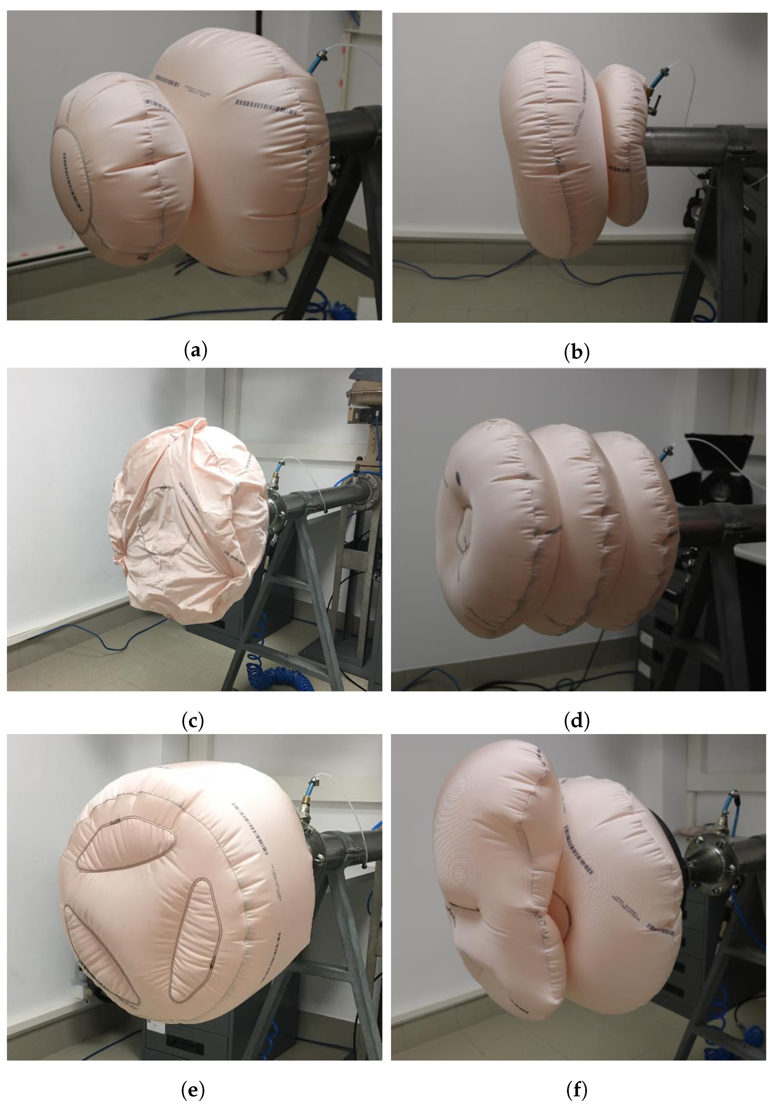
2.1. Airbag Geometries

The airbag geometry influences the level of protection it provides [18]. Therefore, it was necessary to investigate what geometry is more suitable for both assisted and autonomous driving modes. Various geometries were constructed and then analysed regarding how they fulfil the objectives. As a starting point, the geometries previously studied by Esteves [22] were analysed:
Double:
Composed of a standard airbag at the back (steering wheel side) and a smaller airbag located at the front (passenger side) (Figure 1a). When the vehicle is driven in assisted mode, the standard airbag deploys. When driven in autonomous mode, both airbags deploy.
Double inverted:
Geometrically opposite to the previous one (Figure 1b); nevertheless, the deployment is equal, i.e., the standard size airbag deploys when the vehicle is driven in assisted mode, and the whole airbag deploys when driven in autonomous mode.
Double chamber:
The airbag has two internal chambers non-visible from the exterior (Figure 1c). One chamber is deployed in assisted driving mode. In autonomous driving, both chambers are inflated.
Triple chamber:
Geometrically bellows-shaped (Figure 1d). Similarly to the previous cases, part of the airbag is deployed during assisted driving mode while the full airbag is deployed during autonomous driving. However, it is necessary to use constraining structures to control the airbag size.
Cylinder:
Offers a concept similar to the previous one while being geometrically simpler (Figure 1e). Therefore, it requires constraining structures to control the volume and extension of the airbag depending on the driving mode.
Pillow:
This concept is similar to the double chamber geometry. However, the connection between the two airbags is located upwards instead of centred (Figure 1f). The accessory bag has a rectangular shape. The displaced geometry aims to protect the driver even if not properly seated.
The geometry selection was based on their theoretical capability of offering protection during autonomous driving. The geometries were tested experimentally by inflating them with compressed air, allowing to identify their advantages and disadvantages (Figure 1). The airbags employed in these tests were made of PA 470 dTex fabric coated with 25 g of silicone. Following the testing, five parameters were evaluated for all the geometries:
Cost:
The manufacturer’s production costs, lower costs were preferred;
Reach:
Extension of the deployed airbag, i.e., distance from the steering wheel to the airbag’s front panel;
Volume:
How much volume does the folded airbag occupy?
Possibility of adjustment:
How easy is it to modify the airbag’s dimensions to suit a specific application case?
Adaptive systems:
How easy is it to implement a system to alter the airbag reach to suit two driving modes: assisted and autonomous?
A multiple-criteria decision analysis (MCDA) was performed with these parameters [23], being graded as excellent (10), good (5), average (3), below average (3), and poor (1); the number inside the parenthesis indicate the points given in each case. The punctuation attributed to each airbag geometry and parameter were selected from the company’s previous experiences. Subsequently, the two geometries with the higher punctuation are selected for further study.

2.2. Adaptive Systems
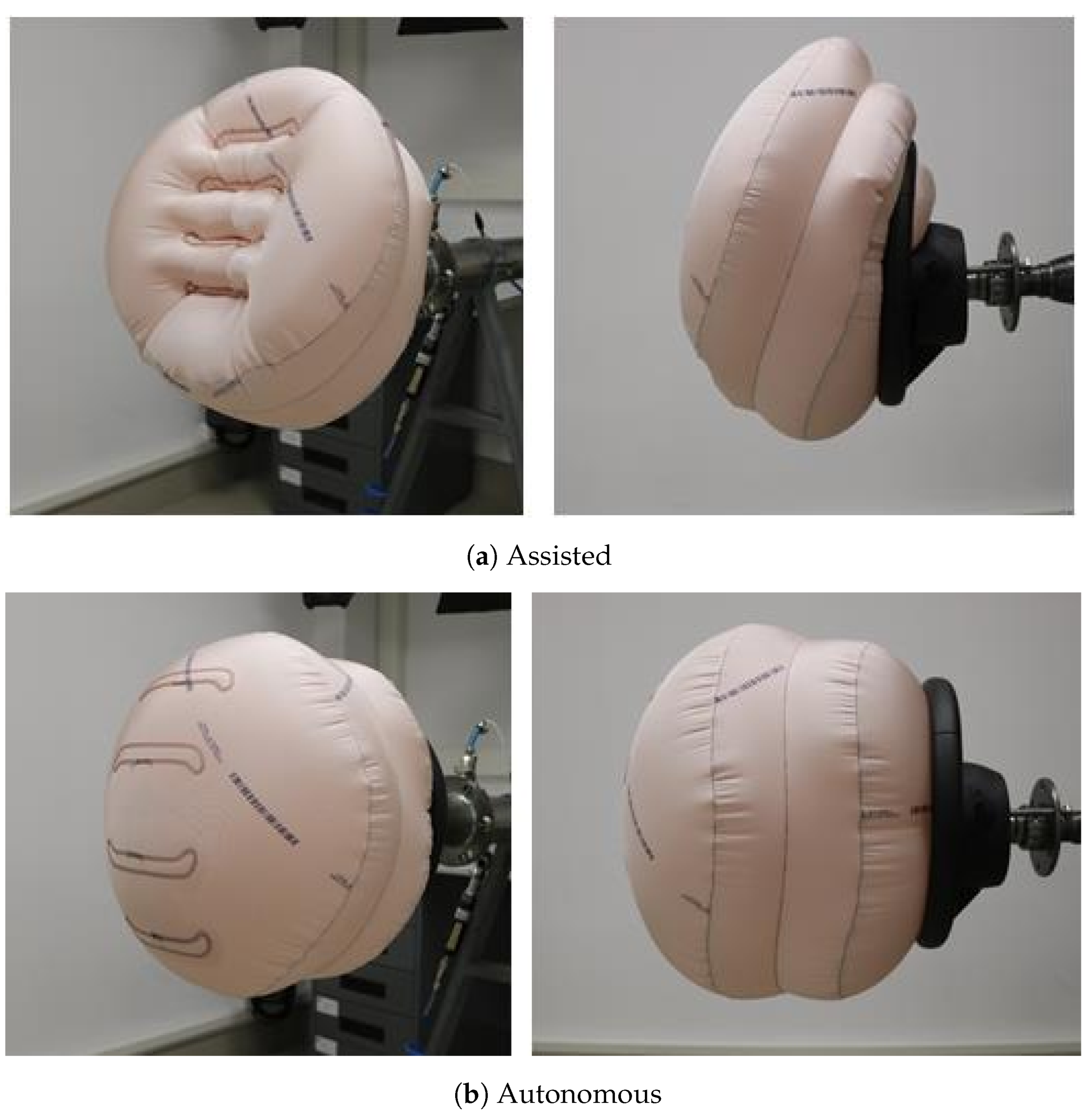
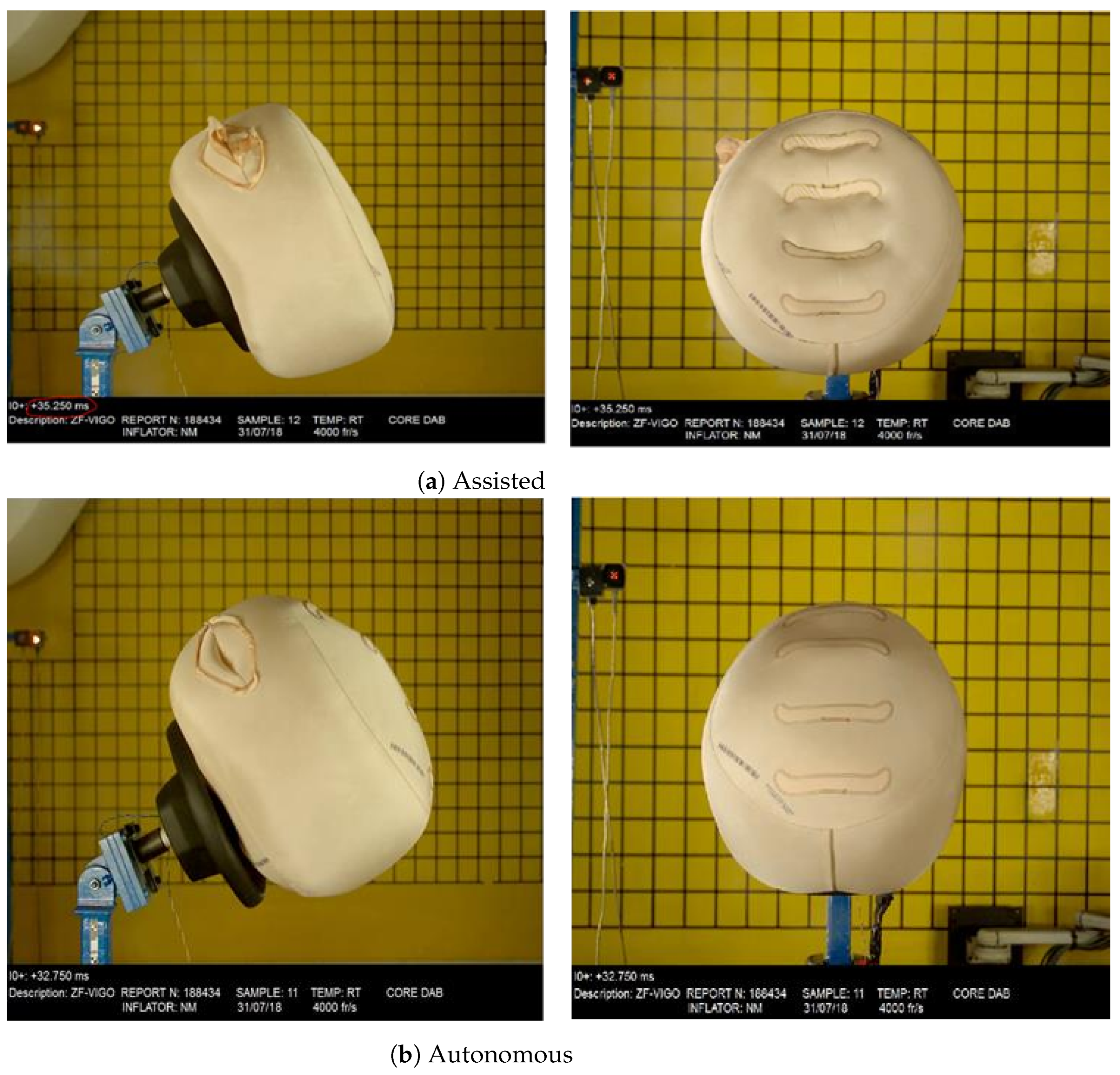
The proposed solution to control the driver’s airbag volume for both driving conditions consists of a sewed internal strap that limits the deployed airbag’s reach (height), also known as ‘tethers’ (Figure 2); the tethers must be strong enough to support this inflating pressure. Nevertheless, when in autonomous driving mode and when the driver’s seat is away from the steering wheel, the airbag is subjected to a higher inflating pressure, breaking the seams in the tethers and allowing for maximum airbag reach. Therefore, the strength of those tethers must be predictable and with lower variability. The strength of the tethers would then depend on the strength of the threads conforming the seams, the seam geometries, and the fabric material employed [24,25]. Two values of inflating pressure were used in this proposal, one per driving mode. It is worth noting that the inflating system is out of the scope of this work. Here, the airbag’s reach for assisted driving was considered to be 300 mm and 400 mm for autonomous driving. These values are internal design requirements while the other dimensions are confidential. Similarly, it is expected that the seams can support 2000 N, which is another internal design requirement.
Currently, the company employs six different thread types (Table 1) in the manufacture of airbags. Three of these are placed on the upper part of the seam (threads 70, 78, and 79) while the remaining are placed in the lower one (threads 69, 71, and 88). However, seam strength not only depends on the thread type but on other parameters such as fabric, cord treatment, seam threads, seam geometry, curtain orientation, and seam tension [24,25]. Therefore, the effect of these six parameters was further studied to identify the most suitable combination to be used in the tethers.
Starting with the six parameters influencing seam strength, a Design of Experiments (DoE) was performed to identify the parameters or the combination of them that influence the most the seam strength; this analysis was done within the Minitab 17 Statistical Software (Minitab Inc., Philadelphia, PA, USA, 2010). After completing the DoE, the parameters identified were (1) the seam’s threads, (2) the seam’s geometry, and (3) tension in the seam’s threads, as shown in Figure 3. In consequence, the influence of these parameters was investigated further, as described in the following sections.

2.2.1. Seam Threads

Seam strength depends on the strength of the threads used in the seam [25]. As mentioned above, three thread types are used for the upper seam while three different ones are used for the lower seam, resulting in six combinations. Then, 29 specimens of each seam combination (174 specimens in total) were tested experimentally following the standard ISO2062. After completion of the tests, a single-factor analysis of variance (ANOVA) was performed to evaluate the effects of these thread combinations.

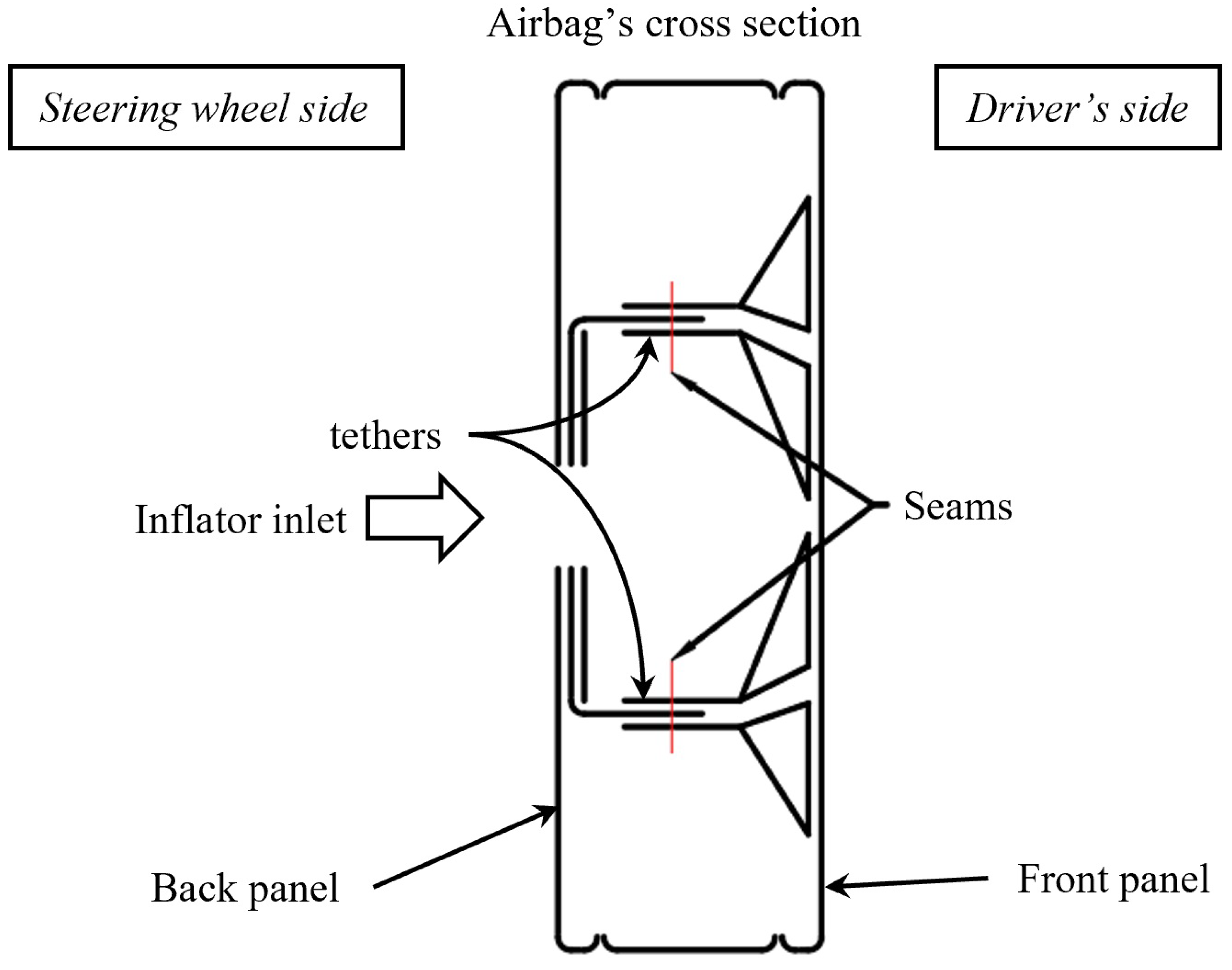
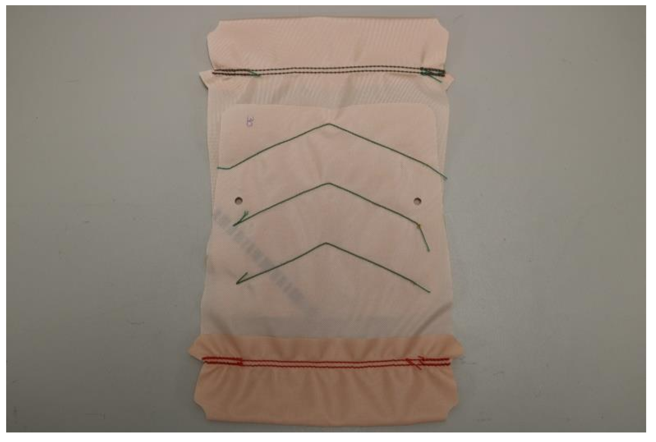
2.2.2. Seam Geometry
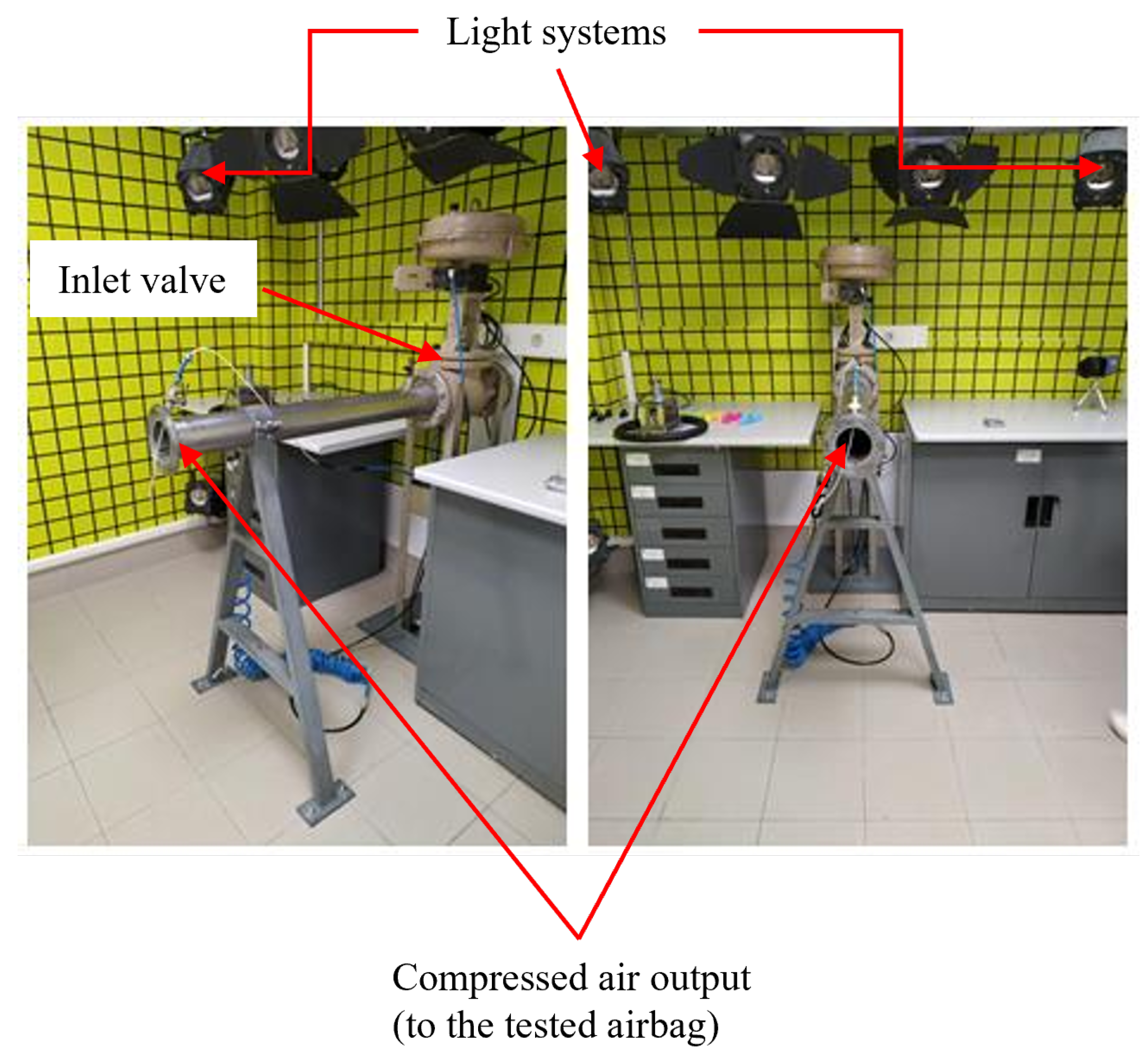
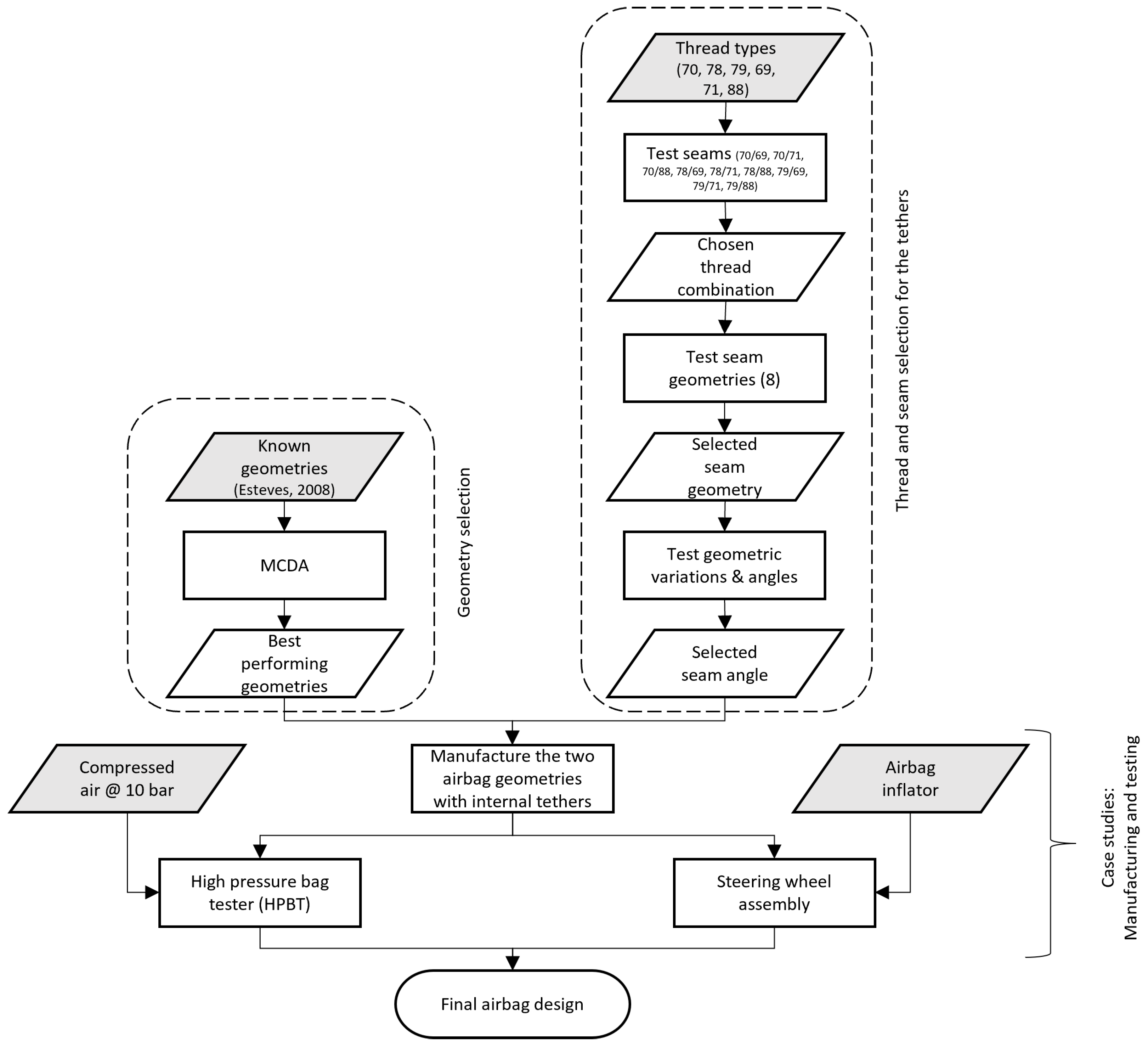
The seam geometry was evaluated on a 700 dTex fabric coated with silicone (Figure 4). The seams were created with nylon threads, the upper was a Tex 30 Anefil Nylon® while the lower was a Tex 138. The mechanical tests were performed using a Universal Testing Machine (UTM) INSTRON with a 10 kN load cell. All the tests were performed at 200 mm/s and had a 5 kN preload; moreover, the gauge length for all the specimens was 200 mm [26]. An example of the specimens is shown in Figure 4.
Eight seam geometries were tested, such as: (1) squared “U”, (2) semicircle, (3) “U”, (4) “O”, (5) skinny squared “U”, (6) eye, (7) “V”, and (8) curved “V”; all of them with 10 stitches except for the skinny squared “U” with 11. Subsequently, variations of the chosen seam geometry were studied to identify if the variations contribute to strength improvement.

2.3. Case Study

Airbags with geometries, thread combinations, and seam geometries selected in the previous steps were manufactured and tested. The airbag testing was done in two stages: first, using a high-pressure bag tester (HPBT); second, using a steering wheel assembly and an inflator module. All the tests were performed in ZF’s experimental facilities in Portugal.
The HPBT was developed by ZF and consists of a compressed air reservoir with a capacity of 10,000 L. The compressed air is stored at 10 bar. The output of this reservoir is connected to the laboratory where the airbags are tested (Figure 5). Furthermore, image-based measurement techniques are employed in the HPBT laboratory, allowing to determine the airbags’ dimensions during and after the inflation tests, for which a photographic camera was used (Canon EOS 800D+18-55MM F/4-5.6 IS STM). The UTM mentioned above is located within the same facilities.

3. Results

The summarised methodology followed in this work is represented in Figure 6. The results of each step indicated there are described in the following subsections.

3.1. Airbag Geometry

Six airbag geometries were analysed using an MCDA and five parameters were considered: (1) manufacture cost, (2) airbag reach, (3) airbag’s volume when stored, (4) adjustment easiness, and (5) suitability for adaptive systems; these parameters were described in Section 2.1. The MCDA is shown in Table 2. Two geometries obtained the highest scores, the bellows and the cylinder, Figure 1d,e. Therefore, these two geometries will be the subject of further study within this work.

3.2. Adaptive Systems
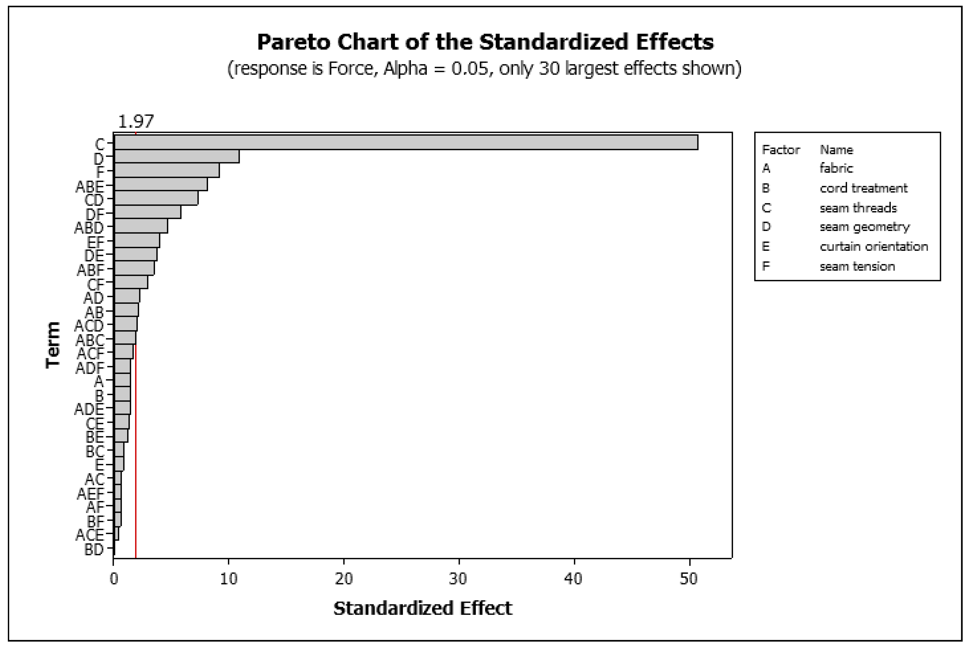
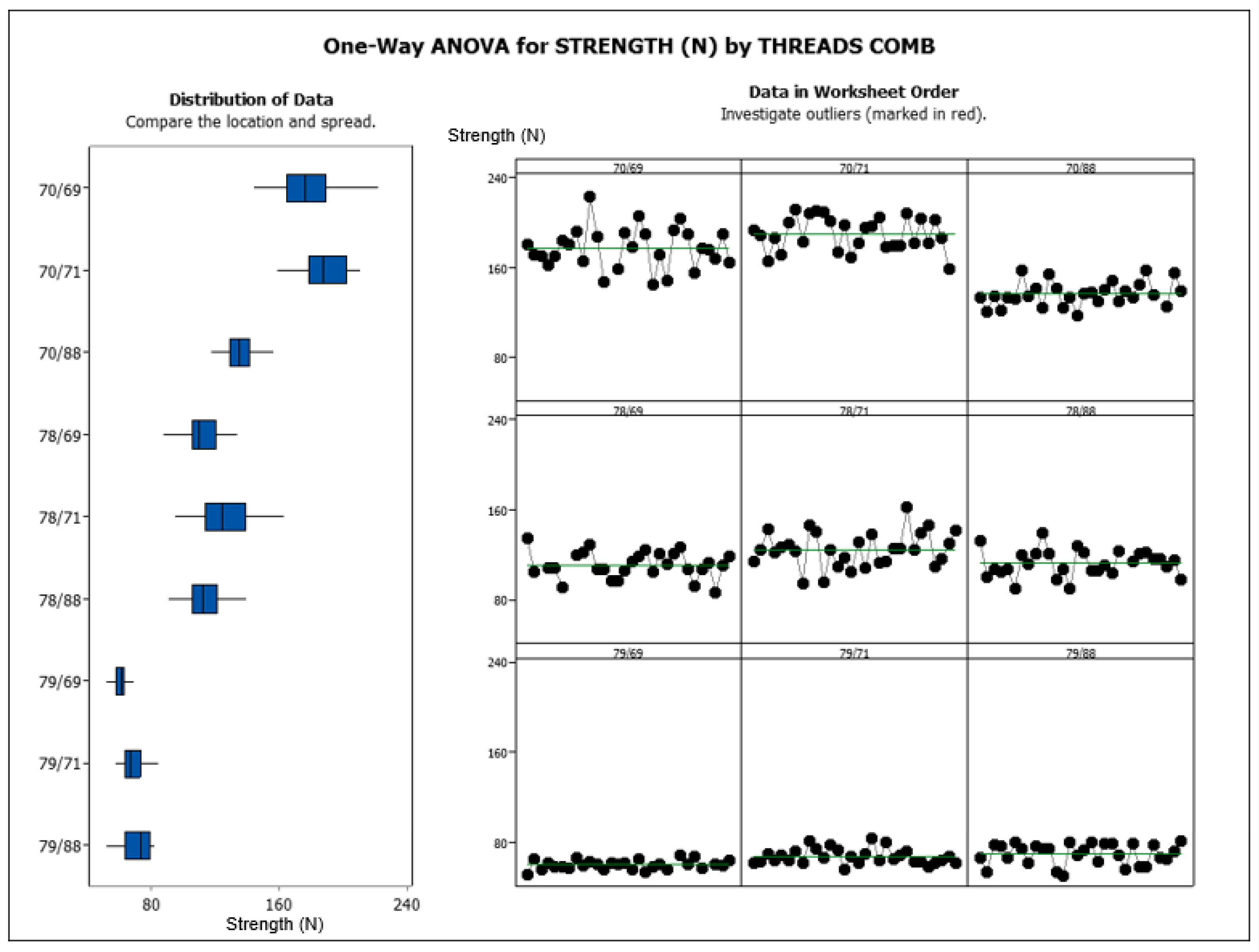
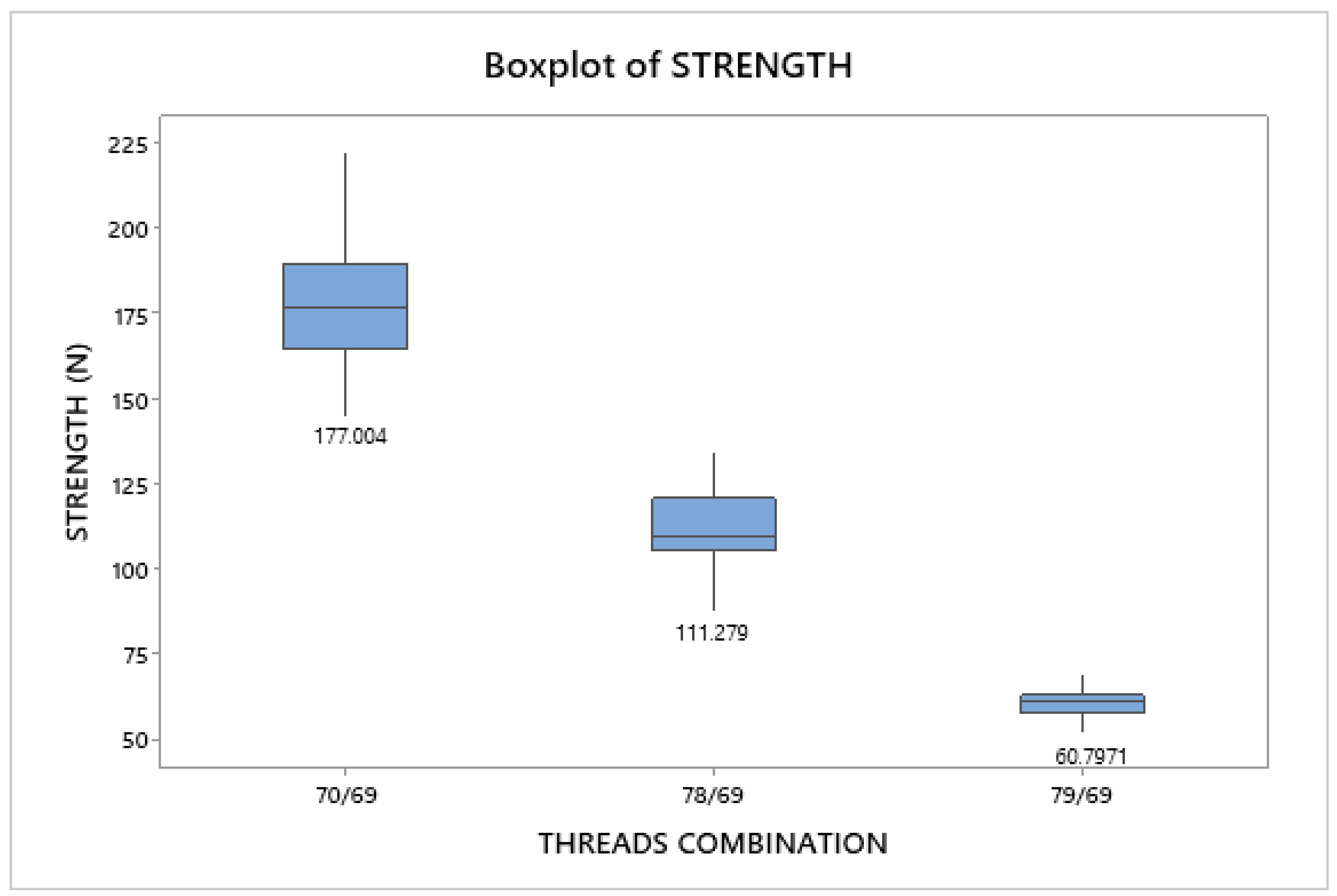
3.2.1. Seam Threads

Seam strength was tested for each of the 6 thread combinations described in Section 2.2; also, 29 specimens per seam type were tested, giving a total of 174 specimens. Seam strength was found to be related to the thread combinations; then, the results were grouped by the type of thread used on the upper seam, as shown in Figure 7. It is worth noting that for the thread combinations 78/69 and 79/69 only 27 specimens were valid (Figure 7).
The thread with reference 69 was the strongest of those employed in the lower seam, so its use ensured that thread failure could only occur in the upper seam. The seams where the thread with reference 70 was placed on the upper seam were found to be the strongest of the set, mainly the 70/69 combination; however, such a combination also had a large dispersion. Continuing with the seams with the thread with reference 78 in the upper seam, these showed similar strength to those described above, although slightly lower. Conversely, these seams showed lower dispersion. Finally, the seams with the upper seam sewn with thread with reference 79 showed the lowest strength. Subsequently, the three seams groups 70/69, 78/69, and 79/69 were analysed to select one for the next steps of the project. The strength data of the associated seam were grouped, as shown in Figure 8.
Upon inspection of the strength data obtained from the experimental tests, shown in Figure 7 and Figure 8, it was decided to use the seam with the thread combination 78/69 because it showed an intermediate strength ( S = 111.3 N ) of the lot with acceptable variability (Figure 8). The seam with the thread combination 79/69 showed the lowest variability but also the lowest strength; hence, its rejection.

3.2.2. Seam Geometry

Eight seam geometric variations were tested to identify the most suitable one to be applied to the tethers (Section 2.2.2). Among the eight seam geometries tested, the squared “U” shape showed the highest strength (173.3 N); however, this geometry also presents one of the highest variabilities in the results ( C V = 6.6 % ). Conversely, the curved “V” shape showed the lowest strength (67.14 N) and high variability ( C V = 17.7 % ), as shown in Figure 9.
On the other hand, the seams with “O” and “V” shapes had the lower variability, with CVs of 3.5% and 7%, respectively. The “O” shape was found to be stronger (108.57 N) than the “V” shape (74.76 N). Despite the lower strength of the latter two configurations with respect to the squared “U” stitch, they were chosen for further study because of their lower CVs. Seam strength can also be influenced by other parameters such as temperature and humidity; however, these were not considered at this stage.
Although the “V” shaped seam had the lowest strength of the chosen two geometries, it is the easiest to sew. Consequently, it was decided to study the effect that its geometric variations have on seam strength, so five additional geometries were tested: arrow, heart, rombo, teardrop, and “V” shape; each geometry was tested with two thread combinations 78/4 AS and 78/88. The testing procedure was the same as described before.
The geometric variation of the “V-shaped” seam had an effect on seam strength, as shown in Figure 10. However, the strength difference had statistical significance; furthermore, the results presented high variability, which was not desired. Among the analysed geometries, the standard “V-shaped” seam showed the lowest variability; hence, it was selected for further analyses.
Although the seam shape is defined, the angle of the “V” can also be varied, so this parameter was further studied. The “V” angle was varied from 0° to 180° in 10° increments while keeping the fabric, thread type, and seam density constant. Subsequently, 30 specimens of each were manufactured with a polyamide fabric (350 dTex), the upper seam thread was done with a 20/3 Nm thread while the lower with a 60/2 Nm one. The “V” angle influenced the seam’s strength, which was found to increase with the “V” angle, as shown in Figure 11, noting that values for a few low angles were omitted (Figure 11).
Upon further inspection, the strength values obtained with the 30°, 45°, and 60° were statistically similar, so only the 30° was used. Similarly, the 90°, 100°, 110°, and 120° showed such pattern; again, the 90° was used. Then, the 130°case was employed; this being similar to the 140°. The cases above 140° were not considered for further analyses due to their high dispersion. Among the three cases chosen, the 90° presented the lowest dispersion, so it was selected for the “V” shape seam, as shown in Figure 12.
In summary, seam strength depends on thread combination and seam geometry. The aforementioned tests indicate that the thread combination 78/69, the V-shaped seam, and a “V” angle of 90° have low variability. Therefore, these parameters were chosen for a proof-of-concept through a case study.

3.3. Case Study

The airbag is mainly composed of three main components: (1) the front panel, (2) the back panel, and (3) two tethers, the latter connecting the front and back panels (Figure 2). Moreover, in this study, two airbag geometries were employed: (1) cylindrical shape and (2) bellows shape, which were selected in Section 3.1. Then, airbags were manufactured in-house and tested to evaluate their performance under assisted and autonomous driving. For these tests, the airbags had similar dimensions to allow for comparisons. The material employed for airbag manufacture was also PA 470 dTex fabric coated 25 g of silicone (same as in Section 2.1).
The tests showed that once the tethers break, the increase in airbag extension (reach) was 120 mm and 130 mm for the cylindrical and bellows-shaped geometries, respectively, hence increasing the airbag volume. For example, a test of the bellows-shaped geometry is shown in Figure 13. Therefore, this increase in extension allows to protect the driver even when he/she is farther away from the steering wheel, as is the case of autonomous driving.
Afterwards, static tests at ambient temperature were performed to the airbags with the aim of evaluating their structural integrity, inflation time, positioning with respect to the steering wheel, and the performance of the shape control through seams.
The recorded inflation time was 30 ms for both assisted and autonomous driving. The use of tethers to control the airbag volume and shape in both driving modes performed as expected, as shown in Figure 14 for the cylinder-shaped airbag. Therefore, the tests confirmed that the chosen geometries, materials, and shape control via the seams fulfil the safety requirements of both assisted and autonomous driving.

4. Discussion

This work aimed to design an airbag capable of protecting the driver of an autonomous vehicle regardless of the driving mode, which was achieved through an experimental methodology. Experimental methodologies had been employed for developing airbags [18], although, in recent years, the use of CAE systems to perform design tasks is widespread. For example, curtain airbags had been developed and optimised through CAE and CFD methodologies [18,21] or using CAD and machine learning methodologies [19]. However, such computational approaches also require corresponding models, dimensions, properties, etc., of the vehicle or vehicles where the airbag is going to be implemented, which often is confidential; for that reason, generic airbag models are often used in the literature. On the other hand, the airbag presented here was developed within a company producing airbags for several car manufacturers; hence, the proposed airbag complies with internal and international standards, although in the future computational studies could be performed, as in Refs. [7,9,10].
Although airbag designs for autonomous vehicles had been reported in the literature, for example, the ‘Life Cell’ of Autoliv® [17,20], those designs are aimed to protect the occupants of the vehicle, offering mostly lateral protection. On the contrary, the airbag design developed here offers frontal protection to the vehicle’s driver, so these designs are not comparable. Regarding the design process, the geometry of conventional airbags was studied to identify which could perform in both driving scenarios. Esteves [22] studied several airbag geometries for the same company; therefore, those geometries were the starting point for this project. Then, airbag volume could be controlled through tethers, which were not reported in the literature, but textiles and threads were [24,25,26,27]. Furthermore, the materials employed in this work are actual airbag materials and correspond to some of those described by Nayak et al. [3].
The design process of this airbag system was divided into individual tasks, i.e., geometry, seams, seam strength and geometry, and case studies, allowing to verify each step and component prior to introducing them to the whole assembly. In addition, the DoE methodology employed is common practice in many experimental studies and plays an important role in airbag development [15,18,21]. Consequently, the developed airbag design followed the usual route for this type of product.
The tests performed on the proposed geometries, confirm that they perform in accordance with the design requirements. The in-house pressure testing allowed to test the strength of the whole assembly, while its mounting within a steering wheel and using an actual airbag inflator validated its deployment performance. The dimensions of the deployed airbags were determined with image-based techniques, which are commonly employed for these purposes [16,17]. Although the developed airbag geometry was validated experimentally using internal and international standards, these tests were mostly about inflation performance for both driving modes. Therefore, tests with head-shaped impactors would further validate the designs. In addition, computational models would contribute to a deeper understanding of the airbag behaviour during inflation and impact.

5. Conclusions

Although the airbag designs already employed in vehicles can be used in autonomous ones, it is necessary to adapt their design so they properly protect the occupants. However, it has been observed that in vehicles able to drive in both autonomous and assisted modes, the occupant in the driver seat may change seating posture while in autonomous driving, therefore reducing the airbag effectiveness in the case of a collision.
In this work, an airbag geometry to be mounted in the steering wheel and offering protection whether the vehicle is in autonomous driving mode or not, was developed using an experimental methodology. The airbag volume is controlled by tethers sewn internally, which will tear with the inflation pressure. The experimental validation confirmed the expected airbag behaviour for both driving modes. The concept of controlling the airbag volume using tethers was found to be successful, so it can be applied to other airbag geometries such as knee bolsters. Furthermore, to the authors’ best knowledge, this is the first time this type of airbag solution has been reported. Although the geometry was validated experimentally, there is an opportunity for future computational studies regarding this geometry and its performance within the vehicle.
Tether strength was found to be influenced by thread type and its strength, the combination of threads in the upper and lower seam locations, and seam geometry. A “V-shaped” geometry forming a 90° angle was chosen for the tether seam because it showed low dispersion while offering adequate strength (90 N) and being easy to sew. The lower variability of seam strength allowed for a predictable behaviour of the tethers, and in consequence, of the whole airbag.
In summary, the geometry proposed here offers protection to the occupants regardless of the driving mode by controlling the number of chambers inflated, which is controlled electronically. Furthermore, the strength and geometry during and after deployment are controlled through the stitching patterns and thread types as well as their location within the airbag. In consequence, the proposed geometry protects the vehicle occupants regardless of the driving mode in which the vehicle is at the moment of a frontal collision.

Author Contributions

Conceptualisation, B.F. and J.M.A.R.; methodology, B.F. and J.M.A.R.; resources, B.F.; formal analysis, B.F., J.M.A.R. and I.d.J.S.-A.; writing the original draft, B.F., J.M.A.R. and I.d.J.S.-A.; supervision, J.M.A.R. All authors have read and agreed to the published version of the manuscript.

Funding

This research received no external funding.

Institutional Review Board Statement

Not applicable.

Informed Consent Statement

Not applicable.

Data Availability Statement

The data is confidential because of the industrial nature of this project.

Acknowledgments

The authors thank ZF Friedrichshafen Portugal for all the support to complete this project.

Conflicts of Interest

The authors declare no conflict of interest.

Abbreviations

The following abbreviations are used in this manuscript:
ANOVAAnalysis of variance
CAEComputer Aided Engineering
CFDComputational Fluid Dynamics
CVCoefficient of variation
DoEDesign of Experiments
HPBTHigh pressure bag test
MCDAMultiple-criteria decision analysis
NCAPNew Car Assessment Program
NmMetric count (unit), number of hanks of 1000 m/kg
UTMUniversal testing machine

References

  1. Starnes, M. Trends in Non-Fatal Traffic Injuries: 1996–2005; Techreport DOT HS 810 944; National Highway Traffic Safety Administration: Washington, DC, USA, 2008.
  2. Glassbrenner, D. Lives Saved Calculations for Seat Belts and Frontal Air Bags; Techreport DOT HS 811 206; National Highway Traffic Safety Administration: Washington, DC, USA, 2009.
  3. Nayak, R.; Padhye, R.; Sinnappoo, K.; Arnold, L.; Behera, B.K. Airbags. Text. Prog. 2013, 45, 209–301. [Google Scholar] [CrossRef]
  4. Braver, E.R.; Kyrychenko, S.Y.; Ferguson, S.A. Driver Mortality in Frontal Crashes: Comparison of Newer and Older Airbag Designs. Traffic Inj. Prev. 2005, 6, 24–30. [Google Scholar] [CrossRef] [PubMed]
  5. Braver, E.R.; Scerbo, M.; Kufera, J.A.; Alexander, M.T.; Volpini, K.; Lloyd, J.P. Deaths among Drivers and Right-Front Passengers in Frontal Collisions: Redesigned Air Bags Relative to First-Generation Air Bags. Traffic Inj. Prev. 2008, 9, 48–58. [Google Scholar] [CrossRef] [PubMed]
  6. Braver, E.R.; Shardell, M.; Teoh, E.R. How Have Changes in Air Bag Designs Affected Frontal Crash Mortality? Ann. Epidemiol. 2010, 20, 499–510. [Google Scholar] [CrossRef] [PubMed]
  7. Thorbole, C.K. Dangers of Seatback Recline in a Moving Vehicle: How Seatback Recline Increases the Injury Severity and Shifts Injury Pattern. In Proceedings of the ASME International Mechanical Engineering Congress and Exposition, Houston, TX, USA, 13–19 November 2015. [Google Scholar] [CrossRef]
  8. McMurry, T.L.; Poplin, G.S.; Shaw, G.; Panzer, M.B. Crash safety concerns for out-of-position occupant postures: A look toward safety in highly automated vehicles. Traffic Inj. Prev. 2018, 19, 582–587. [Google Scholar] [CrossRef] [PubMed]
  9. Rawska, K.; Gepner, B.; Kulkarni, S.; Chastain, K.; Zhu, J.; Richardson, R.; Perez-Rapela, D.; Forman, J.; Kerrigan, J.R. Submarining sensitivity across varied anthropometry in an autonomous driving system environment. Traffic Inj. Prev. 2019, 20, S123–S127. [Google Scholar] [CrossRef] [PubMed]
  10. Rawska, K.; Gepner, B.; Kerrigan, J.R. Effect of various restraint configurations on submarining occurrence across varied seat configurations in autonomous driving system environment. Traffic Inj. Prev. 2021, 22, S128–S133. [Google Scholar] [CrossRef] [PubMed]
  11. Fagnant, D.J.; Kockelman, K. Preparing a nation for autonomous vehicles: Opportunities, barriers and policy recommendations. TRansportation Res. Part A Policy Pract. 2015, 77, 167–181. [Google Scholar] [CrossRef]
  12. Rhiu, I.; Kwon, S.; Bahn, S.; Yun, M.H.; Yu, W. Research Issues in Smart Vehicles and Elderly Drivers: A Literature Review. Int. J. Hum.-Comput. Interact. 2015, 31, 635–666. [Google Scholar] [CrossRef]
  13. Cui, J.; Liew, L.S.; Sabaliauskaite, G.; Zhou, F. A review on safety failures, security attacks, and available countermeasures for autonomous vehicles. Ad Hoc Netw. 2019, 90, 101823. [Google Scholar] [CrossRef]
  14. Diez, M.; Abajo, J.; de Prada, J.V.; Negro, A.; Fernández, M.T. Sitting posture influence in autonomous vehicles for the evaluation of occupant safety in side impact. Saf. Sci. 2023, 159, 106002. [Google Scholar] [CrossRef]
  15. Diederich, A.; Bastien, C.; Blundell, M. The prediction of autonomous vehicle occupants’ pre-crash motion during emergency braking scenarios. Proc. Inst. Mech. Eng. Part D J. Automob. Eng. 2023, 095440702311532. [Google Scholar] [CrossRef]
  16. Breed, D.; Yurchenko, N.; Vynogradskyy, P.; Kuzmenko, K.; Zhang, S.; Li, B. The analysis and experimental development of aspirated airbags for conventional and autonomous vehicles. In Proceedings of the 26th International Technical Conference on the Enhanced Safety of Vehicles, Eindhoven, The Netherlands, 10–13 June 2019; pp. 122–131. [Google Scholar]
  17. Yurchenko, N.F.; Breed, D.S.; Zhang, S. Design of the Airbag Inflation System Applicable to Conventional and Autonomous Vehicles. Automot. Innov. 2021, 4, 390–399. [Google Scholar] [CrossRef]
  18. Zhang, H.; Ma, D.; Raman, S.V. CAE-Based Side Curtain Airbag Design. SAE Trans. 2004, 113, 488–494. [Google Scholar]
  19. Rad, M.A.; Salomonsson, K.; Cenanovic, M.; Balague, H.; Raudberget, D.; Stolt, R. Correlation-based feature extraction from computer-aided design, case study on curtain airbags design. Comput. Ind. 2022, 138, 103634. [Google Scholar] [CrossRef]
  20. Parvez, M.; Rahman, M.; Samykano, M.; Ali, M.Y. Current advances in fabric-based airbag material selection, design and challenges for adoption in futuristic automobile applications. Mater. Today Proc. 2023. [Google Scholar] [CrossRef]
  21. Yun, Y.W.; Choi, J.S.; Park, G.J. Optimization of an automobile curtain airbag using the design of experiments. Proc. Inst. Mech. Eng. Part D J. Automob. Eng. 2014, 228, 370–380. [Google Scholar] [CrossRef]
  22. Esteves, L.P.d.S. Airbag e a sua concepção: Redução de custos em sacos airbag condutor: Estudo de novos conceitos de sacos. Master’s Thesis, Facultade de Engenharia da Universidade do Porto, Porto, Portugal, 2008. [Google Scholar]
  23. Dieter, G.E.; Schmidt, L.C. Engineering Design, 4th ed.; McGraw-Hill: New York, NY, USA, 2009. [Google Scholar]
  24. Chowdhary, U.; Poynor, D. Impact of stitch density on seam strength, seam elongation, and seam efficiency. Int. J. Consum. Stud. 2006, 30, 561–568. [Google Scholar] [CrossRef]
  25. Ünal, B.Z. The prediction of seam strength of denim fabrics with mathematical equations. J. Text. Inst. 2012, 103, 744–751. [Google Scholar] [CrossRef]
  26. ISO13935-1:2014; Textiles-Seam Tensile Properties of Fabrics and Madeup Textile Articles. Part 1: Determination of Maximum Force to Seam Rupture Using the Strip Method. ISO: Geneva, Switzerland, 2014.
  27. Schwarz, I.G.; Kovačević, S.; Kos, I. Physical–mechanical properties of automotive textile materials. J. Ind. Text. 2014, 45, 323–337. [Google Scholar] [CrossRef]
Figure 1. Tested airbag geometries. (a) Double. (b) Double inverted. (c) Double chamber. (d) Triple chamber (bellows). (e) Cylinder. (f) Pillow.
Eng 04 00146 g001
Figure 2. Cross section schematic of the proposed tether system to control the airbag’s reach. The seams, in red, will break with the inflating pressure in autonomous driving.
Eng 04 00146 g002
Figure 3. Identification of the parameters with larger influence in the seam strength.
Eng 04 00146 g003
Figure 4. Example of a specimen for testing the seam geometry.
Eng 04 00146 g004
Figure 5. Laboratory facilities for the static testing of airbags. The grids on the walls are used for image-based measurements.
Eng 04 00146 g005
Figure 6. Schematic representation of the methodology followed in this work.
Eng 04 00146 g006
Figure 7. Analysis of the seam strength due to the different thread types and sizes. The results are grouped by upper seam thread type.
Eng 04 00146 g007
Figure 8. Seam strength of those with the thread using reference 69, in the lower part of the seam.
Eng 04 00146 g008
Figure 9. Comparison of stitch shape and strength.
Eng 04 00146 g009
Figure 10. Strength of the “V-shaped” seam geometric variations.
Eng 04 00146 g010
Figure 11. Seam strength variations due to the seam angle.
Eng 04 00146 g011
Figure 12. Strength vs. “V” angle from the selected configurations.
Eng 04 00146 g012
Figure 13. Bellows-shaped airbag in both driving modes, oblique and lateral views shown for comparison. The recesses or islands shown in (a) correspond to the tethers’ attachment to the airbag’s front panel; tear of the tether seams can be observed in (b) because the recesses disappeared.
Eng 04 00146 g013
Figure 14. Cylinder-shaped airbag in both driving modes, oblique and lateral views shown for comparison. The recesses or islands shown in (a) correspond to the tethers’ attachment to the airbag’s front panel; tear of the tether seams can be observed in (b) because the recesses disappeared.
Eng 04 00146 g014
Table 1. Thread types, strengths, and other data.
Thread Type (Nm)Tensile StrengthColourReference
120/1 165.5 ± 3.5 Orange9200-0178
60/2 33 ± 5 Black9200-0078
40/3 50 ± 4 Brown9200-0070
20/3 106 ± 9 Red9200-0069
17/3 135 ± 20 Gold9200-0217
13/3 160 ± 17 Green9200-0145
Table 2. Decision matrix for the tested airbag geometries: (I) cost, (II) reach, (III) volume when stored, (IV) ease of adjustment, and (V) adaptive systems.
Parameter and Value
IIIIIIIVV
Airbag Geometry107755Total
Cylinder55555170
Double55353146
Double inverted55353146
Triple1313158
Pillow1333146
Bellows55577190
Disclaimer/Publisher’s Note: The statements, opinions and data contained in all publications are solely those of the individual author(s) and contributor(s) and not of MDPI and/or the editor(s). MDPI and/or the editor(s) disclaim responsibility for any injury to people or property resulting from any ideas, methods, instructions or products referred to in the content.

