
Design Recommendations for Concrete Pryout Capacity of Headed Steel Studs and Post-Installed Anchors


Abstract
:1. Introduction
| empirical factor indicated in the corresponding technical specifications, | |
| characteristic concrete breakout strength of anchor group in tension, | |
| projection area ratio of anchor group in tension, | |
| characteristic concrete breakout strength of single anchor in tension away from edge influence, | |
| empirical factor indicated in the corresponding technical specifications for cracked and uncracked concrete, | |
| characteristic cylinder compressive strength of concrete and | |
| effective embedment depth. |
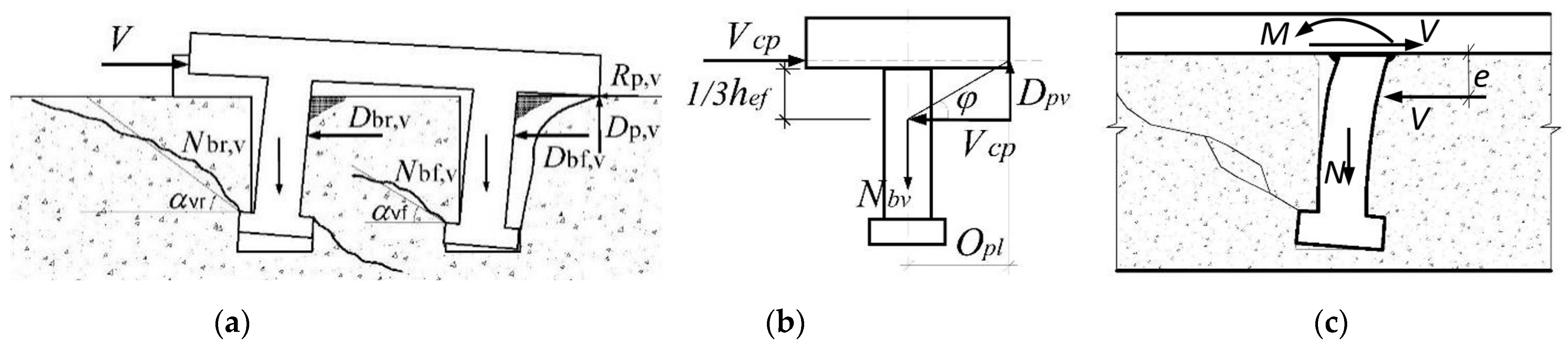
2. Concrete Pryout Prediction Equation for Anchor Groups
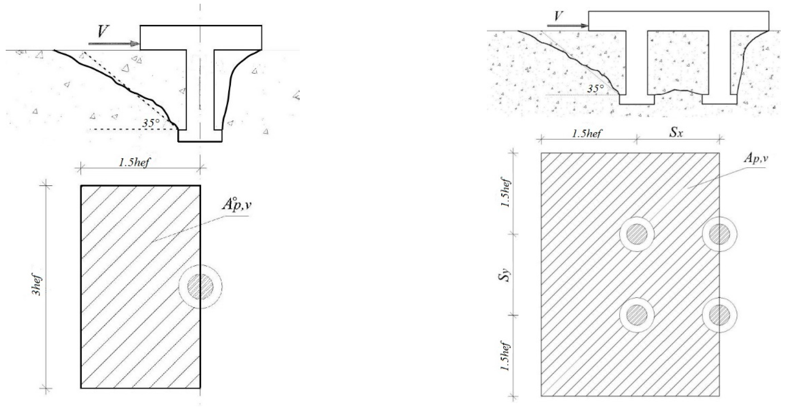
3. Simplified Half-Pyramid Model Implementation
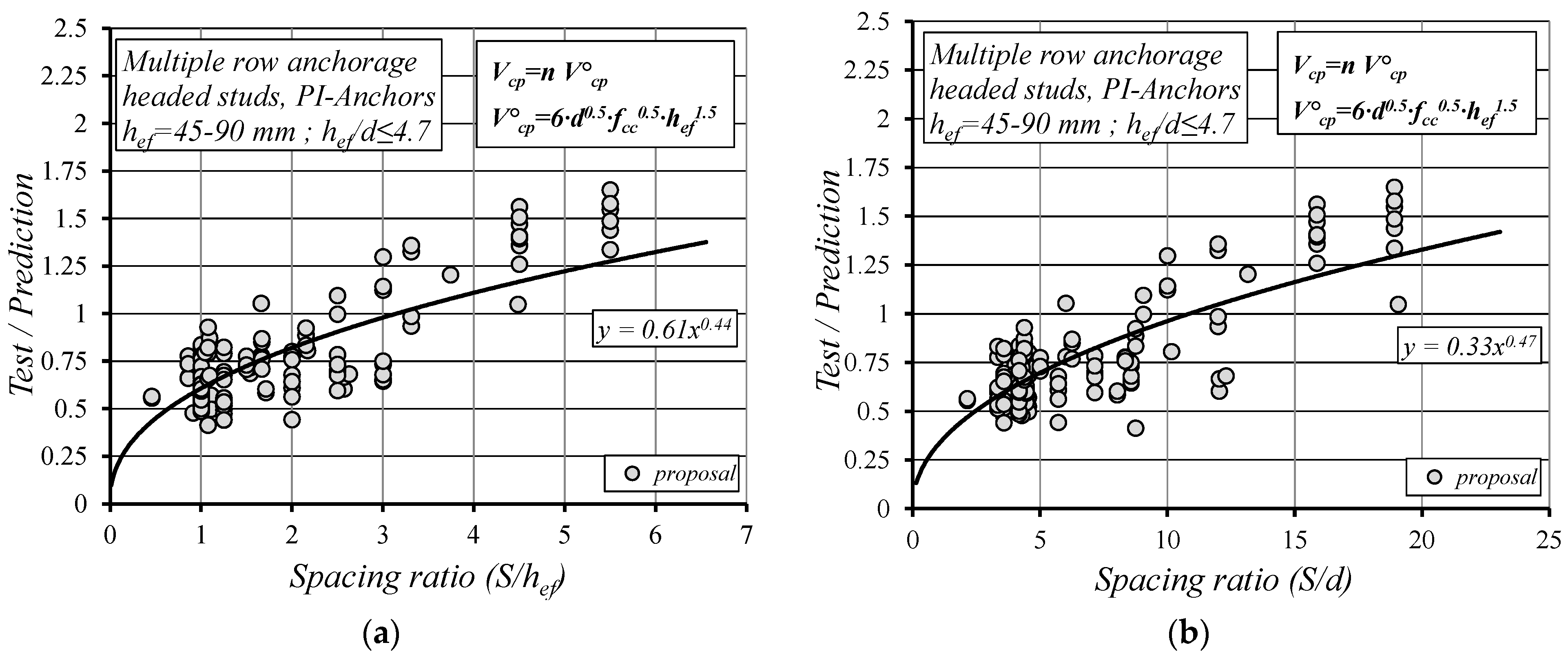
4. Empirical Modification Factor for Multiple Rows
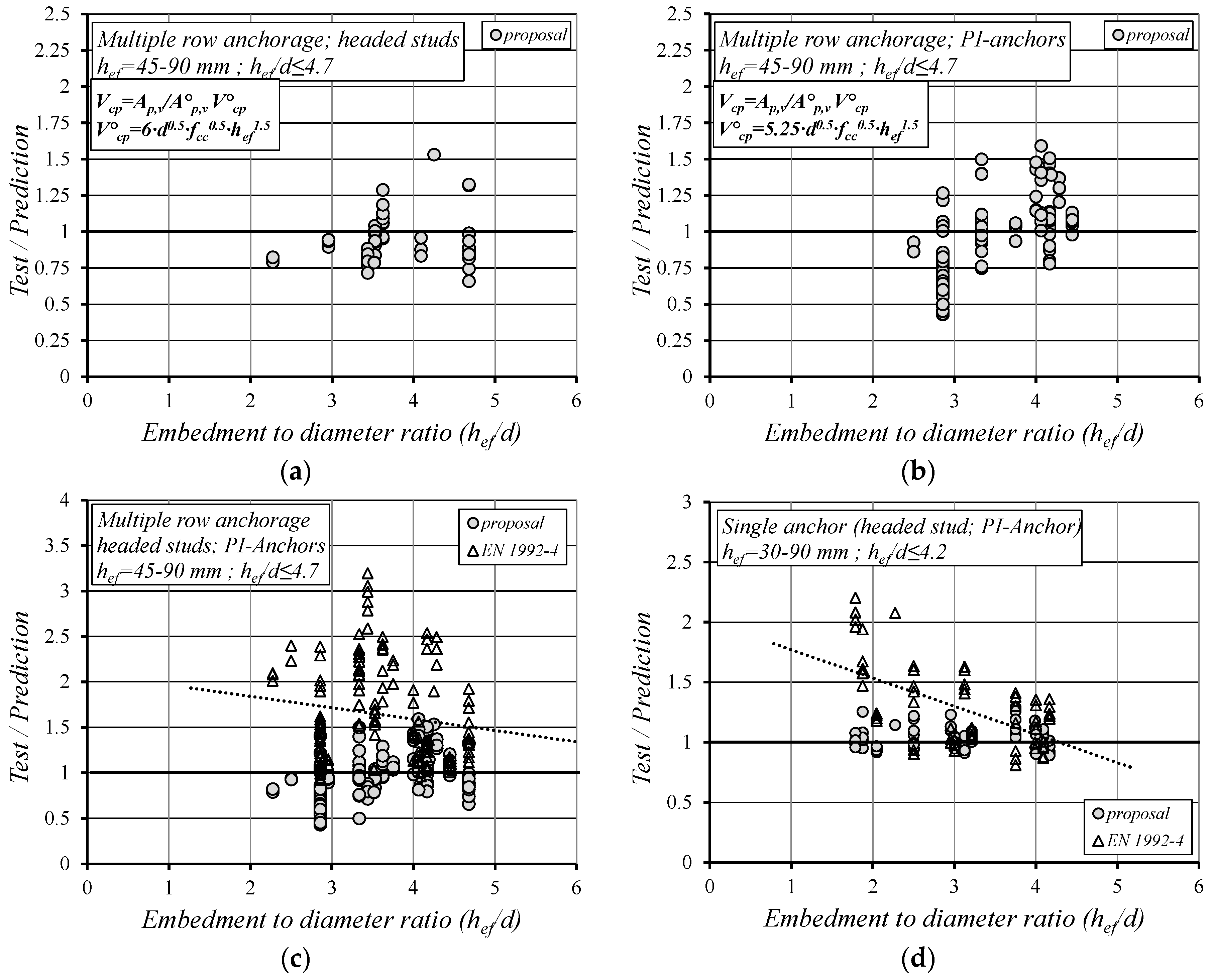
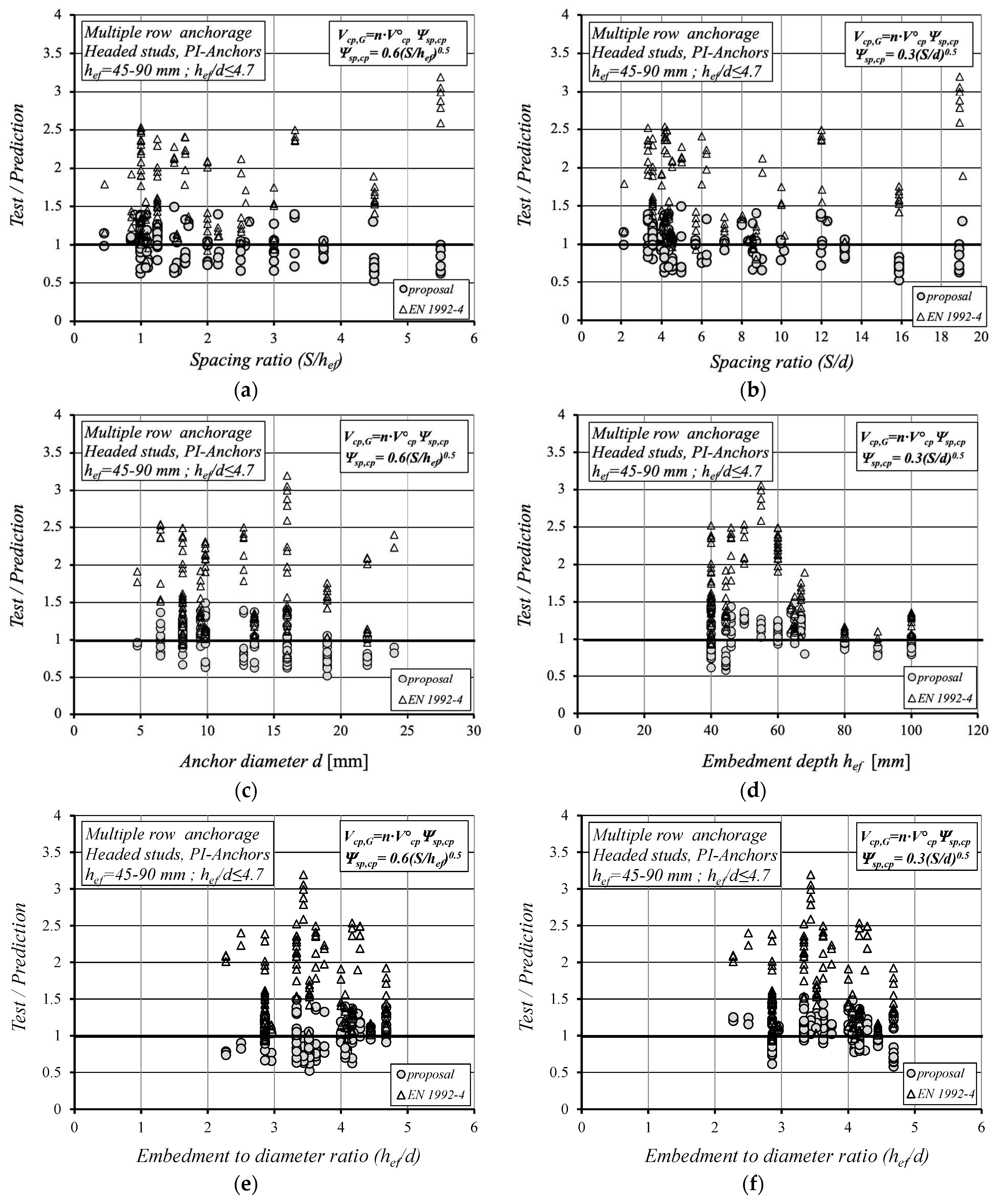
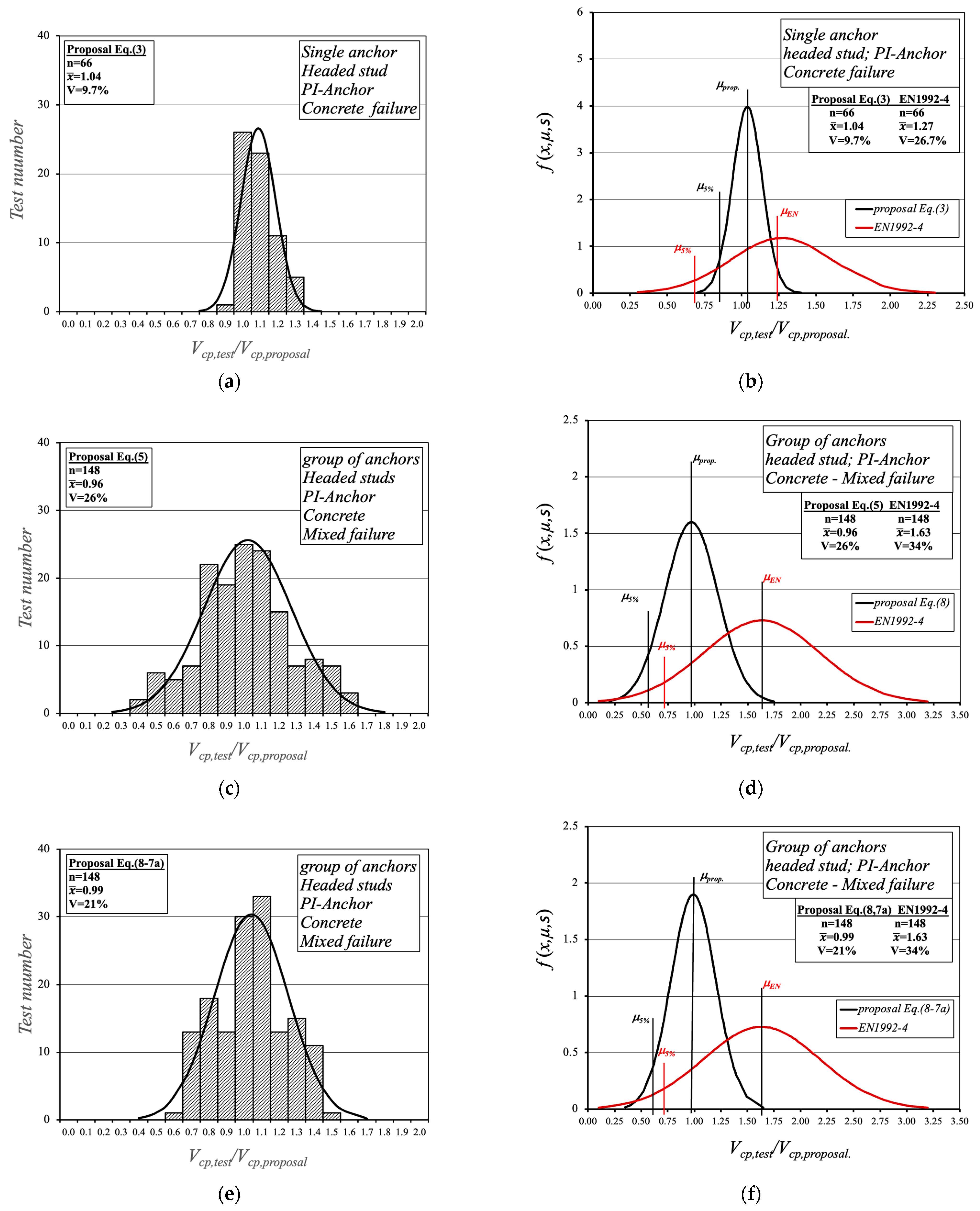
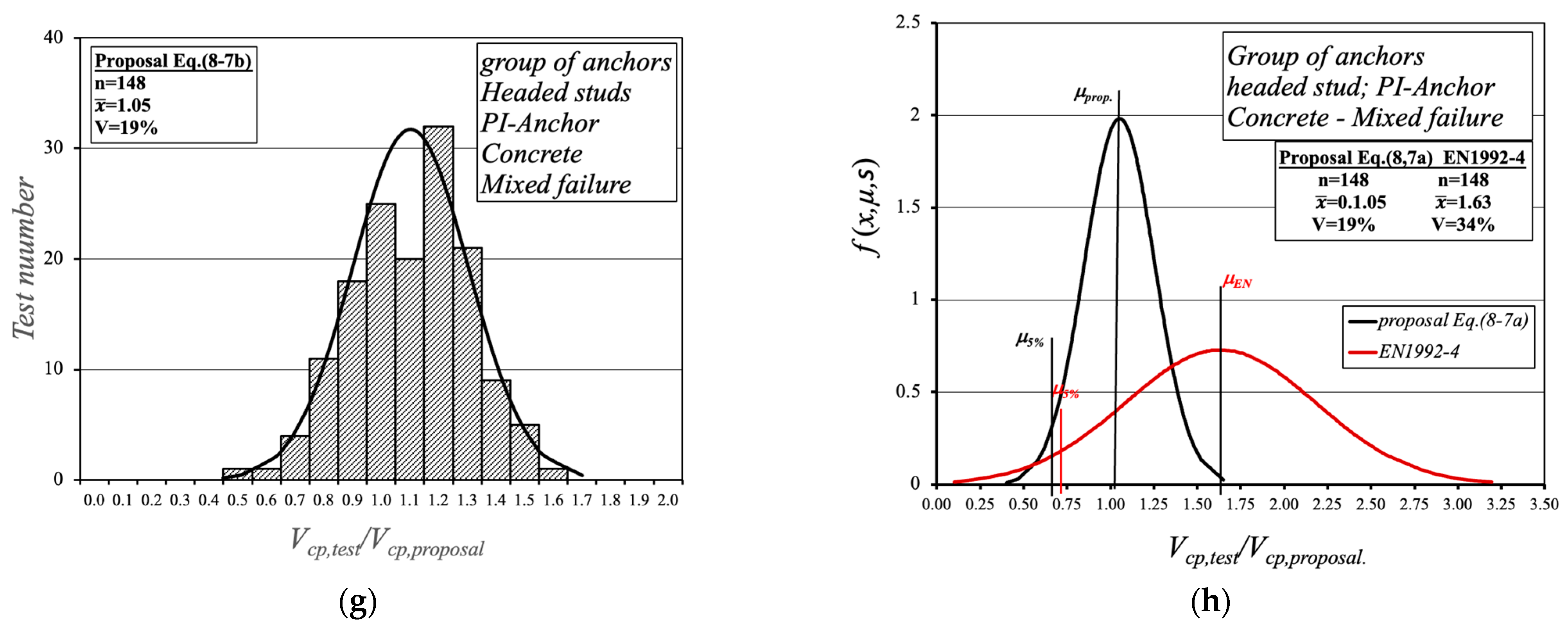
5. Proposed Prediction Methods Versus EN1992-4
6. Conclusions
- The design procedures presented in this paper which are based on a modified indirect-tension breakout model for concrete pryout applying the latest reported prediction formula for a single anchor (Equation (3)) illustrate a good correlation with corresponding influencing parameters.
- The proposed Equation (6) according to the CCD method and Equation (8) using the modifying factors accounting for the stud spacing influence provide better predictors for the pryout capacity of a single anchor and anchor groups (headed stud and post-installed anchor configurations).
- The proposed prediction formulas for a single anchor and groups of anchors utilize the full anchor capacity and depict realistically the real behavior of headed stud and post-installed anchor configurations.
- These design recommendations to predict the pryout capacity of anchor groups are valid for shallowly embedded anchors (hef/d < 4.5) in normal-weight concrete (fc < 50 MPa) away from edge and corner influence.
- The anchor spacing larger than 6d and smaller than 13.5d which corresponds to S = 3hef implies the full pryout capacity of an anchor group.
- The pryout capacity of an anchor group increases proportionally to the square root of both the anchor spacing (S0.5) and the anchor diameter (d0.5).
- Further experimental and numerical investigations are needed to cover the edge and corner influence as well as the impact of high-strength concrete (fc > 50 MPa) on the pryout capacity for both a single anchor and anchor group configuration.
Author Contributions
Funding
Data Availability Statement
Conflicts of Interest
Appendix A

| Investigator | Test Number | Number of Studs | Failure Mode | Embed Depth | Stud Diameter | Concrete Strength | Stiffness Ratio | Anchor Spacing | Anchor Spacing | Peak Load | Proposed | Test/Calc. Proposed | EN 1992 | Test/Calc. EN 1992 |
|---|---|---|---|---|---|---|---|---|---|---|---|---|---|---|
| n | (-) | hef (mm) | d (mm) | fcc (N/mm2) | hef/d | sx (mm) | sy (mm) | Vu,test (kN) | Vu,cal,25 (kN) | Vu,test/Vu,cal | Vu,cal,25 (kN) | Vu,test/Vu,cal | ||
| Single Anchor | ||||||||||||||
| Jebara [11] | KB30-8.1 | 1 | cp | 30.00 | 8.00 | 25.80 | 3.75 | - | - | 17.78 | 13.94 | 1.29 | 12.73 | 1.41 |
| Jebara [11] | KB30-8.2 | 1 | cp | 30.00 | 8.00 | 25.80 | 3.75 | - | - | 16.39 | 13.94 | 1.19 | 12.73 | 1.30 |
| Jebara [11] | KB30-8.3 | 1 | cp | 30.00 | 8.00 | 25.80 | 3.75 | - | - | 16.38 | 13.94 | 1.19 | 12.73 | 1.30 |
| Jebara [11] | KB30-8.4 | 1 | cp | 30.00 | 8.00 | 25.80 | 3.75 | - | - | 17.37 | 13.94 | 1.26 | 12.73 | 1.38 |
| Jebara [11] | KB30-8.5 | 1 | cp | 30.00 | 8.00 | 25.80 | 3.75 | - | - | 14.62 | 13.94 | 1.06 | 12.73 | 1.16 |
| Jebara [11] | KB30-12.1 | 1 | cp | 30.00 | 12.00 | 25.80 | 2.50 | - | - | 20.20 | 17.08 | 1.19 | 12.73 | 1.60 |
| Jebara [11] | KB30-12.2 | 1 | cp | 30.00 | 12.00 | 25.80 | 2.50 | - | - | 20.59 | 17.08 | 1.22 | 12.73 | 1.63 |
| Jebara [11] | KB30-12.3 | 1 | cp | 30.00 | 12.00 | 25.80 | 2.50 | - | - | 17.91 | 17.08 | 1.06 | 12.73 | 1.42 |
| Jebara [11] | KB30-12.4 | 1 | cp | 30.00 | 12.00 | 25.80 | 2.50 | - | - | 18.50 | 17.08 | 1.09 | 12.73 | 1.47 |
| Jebara [11] | KB30-12.5 | 1 | cp | 30.00 | 12.00 | 25.80 | 2.50 | - | - | 16.80 | 17.08 | 0.99 | 12.73 | 1.33 |
| Jebara [11] | KB30-16.1 | 1 | cp | 30.00 | 16.00 | 25.80 | 1.88 | - | - | 18.53 | 19.72 | 0.95 | 12.73 | 1.47 |
| Jebara [11] | KB30-16.2 | 1 | cp | 30.00 | 16.00 | 25.80 | 1.88 | - | - | 21.09 | 19.72 | 1.08 | 12.73 | 1.67 |
| Jebara [11] | KB30-16.3 | 1 | cp | 30.00 | 16.00 | 25.80 | 1.88 | - | - | 19.84 | 19.72 | 1.02 | 12.73 | 1.57 |
| Jebara [11] | KB30-16.4 | 1 | cp | 30.00 | 16.00 | 25.80 | 1.88 | - | - | 24.47 | 19.72 | 1.25 | 12.73 | 1.94 |
| Jebara [11] | KB30-16.5 | 1 | cp | 30.00 | 16.00 | 25.80 | 1.88 | - | - | 20.28 | 19.72 | 1.04 | 12.73 | 1.61 |
| Jebara [11] | KB50-12.1 | 1 | cp | 50.00 | 12.00 | 25.80 | 4.17 | - | - | 32.99 | 36.74 | 0.91 | 27.40 | 1.22 |
| Jebara [11] | KB50-12.2 | 1 | cp | 50.00 | 12.00 | 25.80 | 4.17 | - | - | 33.51 | 36.74 | 0.92 | 27.40 | 1.24 |
| Jebara [11] | KB50-12.3 | 1 | cp | 50.00 | 12.00 | 25.80 | 4.17 | - | - | 35.08 | 36.74 | 0.96 | 27.40 | 1.29 |
| Jebara [11] | KB50-12.4 | 1 | cp | 50.00 | 12.00 | 25.80 | 4.17 | - | - | 32.40 | 36.74 | 0.89 | 27.40 | 1.19 |
| Jebara [11] | KB50-12.5 | 1 | cp | 50.00 | 12.00 | 25.80 | 4.17 | - | - | 36.84 | 36.74 | 1.01 | 27.40 | 1.36 |
| Jebara [11] | KB50-16.1 | 1 | cp | 50.00 | 16.00 | 25.80 | 3.13 | - | - | 43.42 | 42.43 | 1.03 | 27.40 | 1.60 |
| Jebara [11] | KB50-16.2 | 1 | cp | 50.00 | 16.00 | 25.80 | 3.13 | - | - | 44.18 | 42.43 | 1.05 | 27.40 | 1.63 |
| Jebara [11] | KB50-16.3 | 1 | cp | 50.00 | 16.00 | 25.80 | 3.13 | - | - | 40.21 | 42.43 | 0.96 | 27.40 | 1.48 |
| Jebara [11] | KB50-16.4 | 1 | cp | 50.00 | 16.00 | 25.80 | 3.13 | - | - | 38.17 | 42.43 | 0.91 | 27.40 | 1.41 |
| Jebara [11] | KB50-16.5 | 1 | cp | 50.00 | 16.00 | 25.80 | 3.13 | - | - | 39.11 | 42.43 | 0.93 | 27.40 | 1.44 |
| Jebara [11] | KB50-28.1 | 1 | cp | 50.00 | 28.00 | 25.80 | 1.79 | - | - | 54.80 | 56.12 | 0.99 | 27.40 | 2.02 |
| Jebara [11] | KB50-28.2 | 1 | cp | 50.00 | 28.00 | 25.80 | 1.79 | - | - | 59.74 | 56.12 | 1.07 | 27.40 | 2.20 |
| Jebara [11] | KB50-28.3 | 1 | cp | 50.00 | 28.00 | 25.80 | 1.79 | - | - | 56.42 | 56.12 | 1.02 | 27.40 | 2.08 |
| Jebara [11] | KB50-28.4 | 1 | cp | 50.00 | 28.00 | 25.80 | 1.79 | - | - | 53.16 | 56.12 | 0.96 | 27.40 | 1.96 |
| Jebara [11] | KB50-22.3 | 1 | cp | 90.00 | 22.00 | 25.80 | 4.09 | - | - | 115.43 | 120.14 | 0.97 | 132.34 | 0.88 |
| Jebara [11] | KB50-22.4 | 1 | cp | 90.00 | 22.00 | 25.80 | 4.09 | - | - | 115.19 | 120.14 | 0.97 | 132.34 | 0.88 |
| Jebara [11] | KB50-22.5 | 1 | cp | 90.00 | 22.00 | 25.80 | 4.09 | - | - | 113.60 | 120.14 | 0.95 | 132.34 | 0.87 |
| Jebara [11] | KB50-28.1 | 1 | cp | 90.00 | 28.00 | 25.80 | 3.21 | - | - | 137.58 | 135.54 | 1.03 | 132.34 | 1.05 |
| Jebara [11] | KB50-28.2 | 1 | cp | 90.00 | 28.00 | 25.80 | 3.21 | - | - | 143.98 | 135.54 | 1.07 | 132.34 | 1.10 |
| Jebara [11] | KB50-28.3 | 1 | cp | 90.00 | 28.00 | 25.80 | 3.21 | - | - | 134.53 | 135.54 | 1.00 | 132.34 | 1.03 |
| Jebara [11] | KB50-28.4 | 1 | cp | 90.00 | 28.00 | 25.80 | 3.21 | - | - | 138.80 | 135.54 | 1.03 | 132.34 | 1.06 |
| Jebara [11] | KB50-28.5 | 1 | cp | 90.00 | 28.00 | 25.80 | 3.21 | - | - | 146.72 | 135.54 | 1.09 | 132.34 | 1.12 |
| Jebara [11] | KB50-44.1 | 1 | cp | 90.00 | 44.00 | 25.80 | 2.05 | - | - | 160.78 | 169.91 | 0.96 | 132.34 | 1.23 |
| Jebara [11] | KB50-44.2 | 1 | cp | 90.00 | 44.00 | 25.80 | 2.05 | - | - | 162.39 | 169.91 | 0.97 | 132.34 | 1.24 |
| Jebara [11] | KB50-44.3 | 1 | cp | 90.00 | 44.00 | 25.80 | 2.05 | - | - | 154.13 | 169.91 | 0.92 | 132.34 | 1.18 |
| Jebara [11] | KB50-44.4 | 1 | cp | 90.00 | 44.00 | 25.80 | 2.05 | - | - | 157.16 | 169.91 | 0.93 | 132.34 | 1.20 |
| Jebara [11] | KB50-44.5 | 1 | cp | 90.00 | 44.00 | 25.80 | 2.05 | - | - | 162.31 | 169.91 | 0.96 | 132.34 | 1.24 |
| Zhao [12] | 3.1.1 | 1 | cp | 50.00 | 22.00 | 27.00 | 2.27 | - | - | 59.12 | 49.75 | 1.14 | 27.40 | 2.08 |
| Zhao [12] | 3.1.2 | 1 | cp | 65.00 | 22.00 | 27.00 | 2.95 | - | - | 83.95 | 73.74 | 1.10 | 81.23 | 0.99 |
| Zhao [12] | 3.1.3 | 1 | cp | 65.00 | 22.00 | 27.00 | 2.95 | - | - | 94.17 | 73.74 | 1.23 | 81.23 | 1.12 |
| Zhao [12] | 3.1.4 | 1 | cp | 65.00 | 22.00 | 27.00 | 2.95 | - | - | 86.62 | 73.74 | 1.13 | 81.23 | 1.03 |
| Zhao [12] | 3.1.5 | 1 | cp | 90.00 | 22.00 | 27.00 | 4.09 | - | - | 132.47 | 120.14 | 1.06 | 132.34 | 0.96 |
| Zhao [12] | 3.1.6 | 1 | cp | 90.00 | 22.00 | 27.00 | 4.09 | - | - | 130.68 | 120.14 | 1.05 | 132.34 | 0.95 |
| Zhao [12] | 3.1.7 | 1 | cp | 90.00 | 22.00 | 27.00 | 4.09 | - | - | 138.11 | 120.14 | 1.11 | 132.34 | 1.00 |
| Zhao [12] | 3.1.8 | 1 | cp | 115.00 | 22.00 | 27.00 | 5.23 | - | - | 163.71 | 173.53 | 0.94 | 191.15 | 0.86 |
| Hawkins [13] | 1S | 1 | cp | 76.20 | 25.40 | 25.18 | 3.00 | - | - | 105.60 | 100.57 | 1.05 | 103.10 | 1.02 |
| Hawkins [13] | 3S | 1 | cp | 76.20 | 25.40 | 23.75 | 3.00 | - | - | 98.20 | 100.57 | 1.00 | 103.10 | 0.98 |
| Hawkins [13] | 7S | 1 | cp | 76.20 | 25.40 | 40.38 | 3.00 | - | - | 121.10 | 100.57 | 0.95 | 103.10 | 0.92 |
| Hawkins [13] | 11S | 1 | cp | 76.20 | 19.10 | 24.94 | 3.99 | - | - | 102.70 | 87.21 | 1.18 | 103.10 | 1.00 |
| Hawkins [13] | 14S | 1 | cp | 76.20 | 19.10 | 41.33 | 3.99 | - | - | 125.70 | 87.21 | 1.12 | 103.10 | 0.95 |
| Eligehausen and Lehr [23] | 13.1 | 1 | cp | 40.00 | 10.00 | 26.50 | 4.00 | - | - | 23.80 | 21.00 | 1.10 | 17.08 | 1.35 |
| Eligehausen and Lehr [23] | 13.2 | 1 | cp | 40.00 | 10.00 | 26.50 | 4.00 | - | - | 20.60 | 21.00 | 0.95 | 17.08 | 1.17 |
| Eligehausen and Lehr [23] | 13.3 | 1 | cp | 40.00 | 10.00 | 26.50 | 4.00 | - | - | 19.50 | 21.00 | 0.90 | 17.08 | 1.11 |
| Eligehausen and Lehr [23] | 13.4 | 1 | cp | 40.00 | 10.00 | 26.50 | 4.00 | - | - | 19.50 | 21.00 | 0.90 | 17.08 | 1.11 |
| Eligehausen and Lehr [23] | 13.5 | 1 | cp | 40.00 | 10.00 | 26.50 | 4.00 | - | - | 23.00 | 21.00 | 1.06 | 17.08 | 1.31 |
| Grosser [16] | 1 | 1 | cp | 60.00 | 16.00 | 25.00 | 3.75 | - | - | 50.71 | 48.80 | 1.04 | 62.74 | 0.81 |
| Grosser [16] | 2 | 1 | cp | 60.00 | 16.00 | 25.00 | 3.75 | - | - | 57.95 | 48.80 | 1.19 | 62.74 | 0.92 |
| Grosser [16] | 3 | 1 | cp | 60.00 | 16.00 | 25.00 | 3.75 | - | - | 54.05 | 48.80 | 1.11 | 62.74 | 0.86 |
| Grosser [16] | 4 | 1 | cp | 60.00 | 24.00 | 25.00 | 2.50 | - | - | 52.80 | 59.77 | 0.94 | 62.74 | 0.90 |
| Grosser [16] | 5 | 1 | cp | 60.00 | 24.00 | 25.00 | 2.50 | - | - | 56.56 | 59.77 | 0.95 | 62.74 | 0.90 |
| Grosser [16] | 6 | 1 | cp | 60.00 | 24.00 | 25.00 | 2.50 | - | - | 58.54 | 59.77 | 0.98 | 62.74 | 0.93 |
| Group of Anchors (Headed Studs) | ||||||||||||||
|---|---|---|---|---|---|---|---|---|---|---|---|---|---|---|
| Investigator | Test Number | Number of Studs | Failure Mode | Embed Depth | Stud Diameter | Concrete Strength | Stiffness Ratio | Anchor Spacing | Anchor Spacing | Peak Load | Pyramid Model α = 35° | Proposed Vcp = n·V°cp·Ψsp,cp(hef) | Proposed Vcp = n·V°cp·Ψsp,cp(d) | EN 1992-4 |
| n | (-) | hef (mm) | d (mm) | fcc (N/mm2) | hef/d | sx (mm) | sy (mm) | Vu,test (kN) | Vu,cal,25 (kN) | Vu,cal,25 (kN) | Vu,cal,25 (kN) | Vu,cal,25 (kN) | ||
| Zhao [12] | 3.2.1 | 4 | cp | 50.0 | 22.0 | 29.0 | 2.3 | 100.0 | 100.0 | 170.6 | 193.5 | 168.9 | 127.3 | 76.1 |
| Zhao [12] | 3.2.2 | 4 | cp | 50.0 | 22.0 | 29.0 | 2.3 | 100.0 | 100.0 | 164.7 | 193.5 | 168.9 | 127.3 | 76.1 |
| Zhao [12] | 3.2.3 | 4 | cp | 50.0 | 22.0 | 29.0 | 2.3 | 100.0 | 100.0 | 171.8 | 193.5 | 168.9 | 127.3 | 76.1 |
| Zhao [12] | 3.2.4 | 4 | cp | 65.0 | 22.0 | 29.0 | 3.0 | 100.1 | 100.0 | 217.9 | 226.1 | 219.6 | 188.8 | 186.0 |
| Zhao [12] | 3.2.5 | 4 | cp | 65.0 | 22.0 | 29.0 | 3.0 | 100.1 | 100.1 | 227.5 | 226.2 | 219.6 | 188.8 | 186.0 |
| Zhao [12] | 3.2.6 | 4 | cp | 65.0 | 22.0 | 29.0 | 3.0 | 100.1 | 100.1 | 230.1 | 226.2 | 219.6 | 188.8 | 186.0 |
| Zhao [12] | 3.2.7 | 4 | cp | 90.0 | 22.0 | 29.0 | 4.1 | 99.9 | 99.9 | 271.3 | 286.4 | 303.8 | 307.2 | 248.4 |
| Zhao [12] | 3.2.8 | 4 | cp | 90.0 | 22.0 | 29.0 | 4.1 | 99.9 | 99.9 | 295.6 | 286.4 | 303.8 | 307.2 | 248.4 |
| Zhao [12] | 3.2.9 | 4 | cp | 90.0 | 22.0 | 29.0 | 4.1 | 99.9 | 99.9 | 257.3 | 286.4 | 303.8 | 307.2 | 248.4 |
| Anderson and Meinheit [15] | PO4F-6C | 4 | cp | 46.0 | 12.7 | 48.5 | 3.6 | 76.4 | 76.4 | 145.0 | 109.1 | 103.1 | 98.1 | 58.3 |
| Anderson and Meinheit [15] | PO4F-9A | 4 | cp | 46.0 | 12.7 | 48.1 | 3.6 | 115.0 | 76.4 | 184.6 | 138.2 | 126.6 | 120.4 | 68.9 |
| Anderson and Meinheit [15] | PO4F-9B | 4 | cp | 46.0 | 12.7 | 48.0 | 3.6 | 115.0 | 76.4 | 202.4 | 138.2 | 126.6 | 120.4 | 68.9 |
| Anderson and Meinheit [15] | PO4F-12B | 4 | cp | 46.0 | 12.7 | 51.0 | 3.6 | 152.3 | 76.4 | 252.6 | 166.1 | 145.6 | 138.6 | 75.1 |
| Anderson and Meinheit [15] | PO4F-6A | 4 | cp | 46.0 | 12.7 | 48.0 | 3.6 | 76.4 | 76.4 | 194.8 | 109.1 | 103.1 | 98.1 | 58.3 |
| Ollgaard [20] | A(1) | 4 | C | 67.0 | 19.0 | 41.6 | 3.5 | 301.5 | 100.5 | 521.3 | 430.3 | 365.1 | 342.8 | 255.0 |
| Ollgaard [20] | A(2) | 4 | C | 67.0 | 19.0 | 41.6 | 3.5 | 301.5 | 100.5 | 578.2 | 430.3 | 365.1 | 342.8 | 255.0 |
| Ollgaard [20] | A(3) | 4 | C | 67.0 | 19.0 | 41.6 | 3.5 | 301.5 | 100.5 | 544.4 | 430.3 | 365.1 | 342.8 | 255.0 |
| Ollgaard [20] | B(1) | 4 | C | 67.0 | 19.0 | 39.1 | 3.5 | 301.5 | 100.5 | 487.5 | 430.3 | 365.1 | 342.8 | 255.0 |
| Ollgaard [20] | B(2) | 4 | C | 67.0 | 19.0 | 39.1 | 3.5 | 301.5 | 100.5 | 451.9 | 430.3 | 365.1 | 342.8 | 255.0 |
| Ollgaard [20] | B(3) | 4 | C | 67.0 | 19.0 | 39.1 | 3.5 | 301.5 | 100.5 | 451.9 | 430.3 | 365.1 | 342.8 | 255.0 |
| Ollgaard [20] | LA(1) | 4 | C | 67.0 | 19.0 | 29.7 | 3.5 | 301.5 | 100.5 | 435.9 | 430.3 | 365.1 | 342.8 | 255.0 |
| Ollgaard [20] | LA(2) | 4 | C | 67.0 | 19.0 | 29.7 | 3.5 | 301.5 | 100.5 | 471.5 | 430.3 | 365.1 | 342.8 | 255.0 |
| Ollgaard [20] | LA(3) | 4 | C | 67.0 | 19.0 | 29.7 | 3.5 | 301.5 | 100.5 | 439.5 | 430.3 | 365.1 | 342.8 | 255.0 |
| Ollgaard [20] | SA(1) | 4 | C | 55.0 | 16.0 | 32.8 | 3.4 | 302.5 | 99.0 | 346.9 | 365.5 | 275.5 | 255.4 | 101.2 |
| Ollgaard [20] | SA(2) | 4 | C | 55.0 | 16.0 | 32.8 | 3.4 | 302.5 | 99.0 | 370.1 | 365.5 | 275.5 | 255.4 | 101.2 |
| Ollgaard [20] | SA(3) | 4 | C | 55.0 | 16.0 | 32.8 | 3.4 | 302.5 | 99.0 | 354.1 | 365.5 | 275.5 | 255.4 | 101.2 |
| Ollgaard [20] | SB(1) | 4 | C | 55.0 | 16.0 | 33.0 | 3.4 | 302.5 | 99.0 | 323.8 | 365.5 | 275.5 | 255.4 | 101.2 |
| Ollgaard [20] | SB(2) | 4 | C | 55.0 | 16.0 | 33.0 | 3.4 | 302.5 | 99.0 | 300.7 | 365.5 | 275.5 | 255.4 | 101.2 |
| Ollgaard [20] | SB(3) | 4 | C | 55.0 | 16.0 | 33.0 | 3.4 | 302.5 | 99.0 | 334.5 | 365.5 | 275.5 | 255.4 | 101.2 |
| Anderson [15] | PO4F-12B | 4 | M | 46.0 | 12.7 | 51.0 | 3.6 | 152.3 | 76.4 | 258.9 | 166.1 | 145.6 | 138.6 | 75.1 |
| Davies [25] | P44 | 4 | M | 44.5 | 9.5 | 45.2 | 4.7 | 114.3 | 0.0 | 89.0 | 74.4 | 105.5 | 114.1 | 42.7 |
| Davies [25] | P53 | 4 | M | 44.5 | 9.5 | 43.2 | 4.7 | 38.2 | 38.1 | 96.1 | 55.4 | 61.0 | 65.9 | 38.0 |
| Davies [25] | P54 | 4 | M | 44.5 | 9.5 | 43.2 | 4.7 | 114.3 | 0.0 | 96.1 | 74.4 | 105.5 | 114.1 | 42.7 |
| Davies [25] | P83 | 4 | M | 44.5 | 9.5 | 30.8 | 4.7 | 20.3 | 38.1 | 67.6 | 46.0 | 44.4 | 48.1 | 34.0 |
| An and Cederwall [31] | HSC11 | 4 | M | 66.8 | 19.0 | 102.3 | 3.5 | 250.0 | 150.0 | 695.7 | 436.3 | 331.5 | 310.8 | 332.6 |
| An and Cederwall [31] | HSC12 | 4 | M | 66.8 | 19.0 | 96.5 | 3.5 | 250.0 | 150.0 | 675.7 | 436.3 | 331.5 | 310.8 | 332.6 |
| An and Cederwall [31] | HSC21 | 4 | M | 66.8 | 19.0 | 96.5 | 3.5 | 250.0 | 150.0 | 675.7 | 436.3 | 331.5 | 310.8 | 332.6 |
| An and Cederwall [31] | HSC1122 | 4 | M | 66.8 | 19.0 | 108.3 | 3.5 | 250.0 | 150.0 | 715.7 | 436.3 | 331.5 | 310.8 | 332.6 |
| An and Cederwall [31] | NSC11 | 4 | M | 66.8 | 19.0 | 36.5 | 3.5 | 250.0 | 150.0 | 415.9 | 436.3 | 331.5 | 310.8 | 332.6 |
| An and Cederwall [31] | NSC12 | 4 | M | 66.8 | 19.0 | 36.5 | 3.5 | 250.0 | 150.0 | 415.9 | 436.3 | 331.5 | 310.8 | 332.6 |
| An and Cederwall [31] | NSC21 | 4 | M | 66.8 | 19.0 | 36.5 | 3.5 | 250.0 | 150.0 | 415.9 | 436.3 | 331.5 | 310.8 | 332.6 |
| An and Cederwall [31] | NSC22 | 4 | M | 66.8 | 19.0 | 37.8 | 3.5 | 250.0 | 150.0 | 422.6 | 436.3 | 331.5 | 310.8 | 332.6 |
| Davies [25] | P42 | 2 | M | 44.5 | 9.5 | 34.7 | 4.7 | 96.5 | 0.0 | 52.0 | 67.1 | 48.5 | 52.4 | 39.6 |
| Davies [25] | P52 | 2 | M | 44.5 | 9.5 | 34.7 | 4.7 | 38.1 | 0.0 | 42.7 | 43.1 | 30.4 | 32.9 | 29.5 |
| Davies [25] | P62 | 2 | M | 44.5 | 9.5 | 34.7 | 4.7 | 20.3 | 0.0 | 36.5 | 35.7 | 22.2 | 24.0 | 26.5 |
| Davies [25] | P43 | 3 | M | 44.5 | 9.5 | 37.3 | 4.7 | 116.8 | 0.0 | 68.5 | 75.4 | 80.0 | 86.5 | 43.1 |
| Davies [25] | P72 | 3 | M | 44.5 | 9.5 | 37.3 | 4.7 | 76.2 | 0.0 | 58.7 | 58.7 | 64.6 | 69.8 | 36.1 |
| Davies [25] | P73 | 3 | M | 44.5 | 9.5 | 37.3 | 4.7 | 40.6 | 0.0 | 48.0 | 44.1 | 47.1 | 51.0 | 30.0 |
| Davies [25] | P63 | 2 | M | 44.5 | 9.5 | 43.2 | 4.7 | 38.1 | 0.0 | 56.0 | 43.1 | 30.4 | 32.9 | 29.5 |
| Davies [25] | P64 | 2 | M | 44.5 | 9.5 | 45.2 | 4.7 | 38.1 | 0.0 | 54.3 | 43.1 | 30.4 | 32.9 | 29.5 |
| Davies [25] | P74 | 3 | M | 44.5 | 9.5 | 45.2 | 4.7 | 76.2 | 0.0 | 66.7 | 58.7 | 64.6 | 69.8 | 36.1 |
| Anderson [15] | PO6F-6A | 6 | cp | 46.0 | 12.7 | 51.0 | 3.6 | 152.3 | 76.4 | 267.3 | 166.1 | 218.5 | 207.9 | 79.0 |
| Anderson [15] | PO6F-6B | 6 | cp | 46.0 | 12.7 | 51.0 | 3.6 | 152.3 | 76.4 | 281.6 | 166.1 | 218.5 | 207.9 | 79.0 |
| Jayas and Hosein [30] | JS-5 | 8 | C | 68.0 | 16.0 | 35.9 | 4.3 | 305.0 | 76.0 | 676.1 | 368.5 | 684.0 | 705.1 | 297.7 |
| Group of Anchors (Anchor Bolt) | ||||||||||||||
|---|---|---|---|---|---|---|---|---|---|---|---|---|---|---|
| Investigator | Test Number | Number of Studs | Failure Mode | Embed Depth | Stud Diameter | Concrete Strength | Stiffness Ratio | Anchor Spacing | Anchor Spacing | Peak Load | Pyramid Model α = 35° | Proposed Vcp = n·V°cp·Ψsp,cp(hef) | Proposed Vcp = n·V°cp·Ψsp,cp(d) | EN 1992-4 |
| n | (-) | hef (mm) | d (mm) | fcc (N/mm2) | hef/d | sx (mm) | sy (mm) | Vu,test (kN) | Vu,cal,25 (kN) | Vu,cal,25 (kN) | Vu,cal,25 (kN) | Vu,cal,25 (kN) | ||
| Eligehausen and Lehr [23] | HS-4x-H1-1 | 4 | cp | 40.0 | 8.2 | 25.2 | 2.9 | 50.0 | 50.0 | 52.7 | 64.5 | 66.7 | 56.3 | 34.3 |
| Eligehausen and Lehr [23] | HS-4x-H1-2 | 4 | cp | 40.0 | 8.2 | 25.2 | 2.9 | 50.0 | 50.0 | 51.7 | 64.5 | 66.7 | 56.3 | 34.3 |
| Eligehausen and Lehr [23] | HS-4x-H1-3 | 4 | cp | 40.0 | 8.2 | 25.2 | 2.9 | 50.0 | 50.0 | 49.4 | 64.5 | 66.7 | 56.3 | 34.3 |
| Eligehausen and Lehr [23] | HS-4x-H1-4 | 4 | cp | 40.0 | 8.2 | 25.2 | 2.9 | 50.0 | 50.0 | 51.3 | 64.5 | 66.7 | 56.3 | 34.3 |
| Eligehausen and Lehr [23] | HS-4x-H1-5 | 4 | cp | 40.0 | 8.2 | 25.2 | 2.9 | 50.0 | 50.0 | 69.3 | 64.5 | 66.7 | 56.3 | 34.3 |
| Eligehausen and Lehr [23] | HS-4x-H1-6 | 4 | cp | 40.0 | 8.2 | 25.2 | 2.9 | 50.0 | 50.0 | 44.0 | 64.5 | 66.7 | 56.3 | 34.3 |
| Eligehausen and Lehr [23] | HS-4x-H1-7 | 4 | cp | 40.0 | 8.2 | 25.2 | 2.9 | 50.0 | 50.0 | 54.5 | 64.5 | 66.7 | 56.3 | 34.3 |
| Eligehausen and Lehr [23] | HS-4x-H1-8 | 4 | cp | 40.0 | 8.2 | 25.2 | 2.9 | 50.0 | 50.0 | 47.3 | 64.5 | 66.7 | 56.3 | 34.3 |
| Eligehausen and Lehr [23] | HS-4x-H1-9 | 4 | cp | 40.0 | 8.2 | 25.2 | 2.9 | 50.0 | 50.0 | 51.6 | 64.5 | 66.7 | 56.3 | 34.3 |
| Eligehausen and Lehr [23] | HS-4x-H1-10 | 4 | cp | 40.0 | 8.2 | 25.2 | 2.9 | 50.0 | 50.0 | 55.6 | 64.5 | 66.7 | 56.3 | 34.3 |
| Eligehausen and Lehr [23] | HS-4x-H1-11 | 4 | cp | 40.0 | 8.2 | 25.2 | 2.9 | 50.0 | 50.0 | 44.1 | 64.5 | 66.7 | 56.3 | 34.3 |
| Eligehausen and Lehr [23] | HS-4x-H1-12 | 4 | cp | 40.0 | 8.2 | 26.5 | 2.9 | 80.0 | 80.0 | 69.5 | 96.6 | 84.3 | 71.3 | 47.4 |
| Eligehausen and Lehr [23] | HS-4x-H1-13 | 4 | cp | 40.0 | 8.2 | 26.5 | 2.9 | 80.0 | 80.0 | 62.3 | 96.6 | 84.3 | 71.3 | 47.4 |
| Eligehausen and Lehr [23] | HS-4x-H1-14 | 4 | cp | 40.0 | 8.2 | 26.5 | 2.9 | 80.0 | 80.0 | 65.7 | 96.6 | 84.3 | 71.3 | 47.4 |
| Eligehausen and Lehr [23] | HS-4x-H1-15 | 4 | cp | 40.0 | 8.2 | 26.5 | 2.9 | 80.0 | 80.0 | 45.3 | 96.6 | 84.3 | 71.3 | 47.4 |
| Eligehausen and Lehr [23] | HS-4x-H1-16 | 4 | cp | 40.0 | 8.2 | 26.5 | 2.9 | 80.0 | 80.0 | 57.6 | 96.6 | 84.3 | 71.3 | 47.4 |
| Eligehausen and Lehr [23] | HS-4x-H1-17 | 4 | cp | 40.0 | 8.2 | 26.5 | 2.9 | 100.0 | 100.0 | 71.7 | 121.5 | 94.3 | 79.7 | 57.4 |
| Eligehausen and Lehr [23] | HS-4x-H1-18 | 4 | cp | 40.0 | 8.2 | 26.5 | 2.9 | 100.0 | 100.0 | 80.3 | 121.5 | 94.3 | 79.7 | 57.4 |
| Eligehausen and Lehr [23] | HS-4x-H1-19 | 4 | cp | 40.0 | 8.2 | 26.5 | 2.9 | 100.0 | 100.0 | 69.2 | 121.5 | 94.3 | 79.7 | 57.4 |
| Eligehausen and Lehr [23] | HS-4x-H1-20 | 4 | cp | 40.0 | 8.2 | 26.5 | 2.9 | 100.0 | 100.0 | 75.0 | 121.5 | 94.3 | 79.7 | 57.4 |
| Eligehausen and Lehr [23] | HS-4x-H1-21 | 4 | cp | 40.0 | 8.2 | 26.5 | 2.9 | 100.0 | 100.0 | 61.0 | 121.5 | 94.3 | 79.7 | 57.4 |
| Eligehausen and Lehr [23] | HS-4x-H1-22 | 4 | cp | 40.0 | 8.2 | 26.5 | 2.9 | 120.0 | 120.0 | 66.0 | 149.1 | 103.3 | 87.3 | 68.3 |
| Eligehausen and Lehr [23] | HS-4x-H1-23 | 4 | cp | 40.0 | 8.2 | 26.5 | 2.9 | 120.0 | 120.0 | 75.1 | 149.1 | 103.3 | 87.3 | 68.3 |
| Eligehausen and Lehr [23] | HS-4x-H1-24 | 4 | cp | 40.0 | 8.2 | 26.5 | 2.9 | 120.0 | 120.0 | 66.8 | 149.1 | 103.3 | 87.3 | 68.3 |
| Lehr and Eligehausen [24] | HS-4x-H1-1 | 4 | cp | 40.0 | 8.2 | 26.5 | 2.9 | 120.0 | 120.0 | 69.6 | 149.1 | 103.3 | 87.3 | 68.3 |
| Lehr and Eligehausen [24] | HS-4x-H1-2 | 4 | cp | 40.0 | 8.2 | 26.5 | 2.9 | 120.0 | 120.0 | 76.8 | 149.1 | 103.3 | 87.3 | 68.3 |
| Lehr and Eligehausen [24] | HS-4x-H2-3 | 4 | cp | 60.0 | 9.9 | 26.9 | 3.3 | 60.0 | 60.0 | 128.6 | 115.0 | 124.2 | 113.4 | 55.8 |
| Lehr and Eligehausen [24] | HS-4x-H2-4 | 4 | cp | 60.0 | 9.9 | 26.9 | 3.3 | 60.0 | 60.0 | 120.5 | 115.0 | 124.2 | 113.4 | 55.8 |
| Lehr and Eligehausen [24] | HS-4x-H2-5 | 4 | cp | 60.0 | 9.9 | 26.9 | 3.3 | 60.0 | 60.0 | 110.2 | 115.0 | 124.2 | 113.4 | 55.8 |
| Lehr and Eligehausen [24] | HS-4x-H2-6 | 4 | cp | 60.0 | 9.9 | 26.9 | 3.3 | 60.0 | 60.0 | 114.3 | 115.0 | 124.2 | 113.4 | 55.8 |
| Lehr and Eligehausen [24] | HS-4x-H2-7 | 4 | cp | 60.0 | 9.9 | 26.9 | 3.3 | 60.0 | 60.0 | 133.5 | 115.0 | 124.2 | 113.4 | 55.8 |
| Lehr and Eligehausen [24] | HS-4x-H28 | 4 | cp | 60.0 | 9.9 | 30.2 | 3.3 | 90.0 | 90.0 | 176.6 | 155.3 | 152.1 | 138.9 | 70.6 |
| Lehr and Eligehausen [24] | HS-4x-H2-9 | 4 | cp | 60.0 | 9.9 | 30.2 | 3.3 | 90.0 | 90.0 | 164.7 | 155.3 | 152.1 | 138.9 | 70.6 |
| Lehr and Eligehausen [24] | HS-4x-H2-10 | 4 | cp | 60.0 | 9.9 | 30.2 | 3.3 | 90.0 | 90.0 | 165.2 | 155.3 | 152.1 | 138.9 | 70.6 |
| Lehr and Eligehausen [24] | HS-4x-H2-11 | 4 | cp | 60.0 | 9.9 | 30.2 | 3.3 | 90.0 | 90.0 | 161.0 | 155.3 | 152.1 | 138.9 | 70.6 |
| Lehr and Eligehausen [24] | HS-4x-H2-12 | 4 | cp | 60.0 | 9.9 | 30.2 | 3.3 | 90.0 | 90.0 | 166.2 | 155.3 | 152.1 | 138.9 | 70.6 |
| Lehr and Eligehausen [24] | Sp-4X-T-1 | 4 | cp | 80.0 | 9.9 | 27.1 | 4.4 | 80.0 | 80.0 | 191.9 | 177.1 | 191.3 | 201.6 | 171.7 |
| Lehr and Eligehausen [24] | Sp-4X-T-2 | 4 | cp | 80.0 | 9.9 | 27.1 | 4.4 | 80.0 | 80.0 | 180.7 | 177.1 | 191.3 | 201.6 | 171.7 |
| Lehr and Eligehausen [24] | HS-4x-H3-1 | 4 | cp | 100.0 | 13.6 | 25.8 | 4.2 | 100.0 | 100.0 | 253.9 | 285.8 | 308.6 | 315.0 | 240.0 |
| Lehr and Eligehausen [24] | HS-4x-H3-2 | 4 | cp | 100.0 | 13.6 | 25.8 | 4.2 | 100.0 | 100.0 | 261.8 | 285.8 | 308.6 | 315.0 | 240.0 |
| Lehr and Eligehausen [24] | HS-4x-H3-3 | 4 | cp | 100.0 | 13.6 | 25.8 | 4.2 | 100.0 | 100.0 | 299.5 | 285.8 | 308.6 | 315.0 | 240.0 |
| Lehr and Eligehausen [24] | HS-4x-H3-4 | 4 | cp | 100.0 | 13.6 | 25.8 | 4.2 | 100.0 | 100.0 | 330.4 | 285.8 | 308.6 | 315.0 | 240.0 |
| Lehr and Eligehausen [24] | HS-4x-H3-5 | 4 | cp | 100.0 | 13.6 | 25.8 | 4.2 | 100.0 | 100.0 | 285.8 | 285.8 | 308.6 | 315.0 | 240.0 |
| Lehr and Eligehausen [24] | Sp-4X-T-1 | 4 | cp | 40.0 | 4.8 | 33.6 | 4.0 | 40.0 | 40.0 | 62.3 | 46.7 | 50.4 | 50.4 | 30.4 |
| Lehr and Eligehausen [24] | Sp-4X-T-2 | 4 | cp | 40.0 | 4.8 | 29.8 | 4.0 | 40.0 | 40.0 | 63.3 | 46.7 | 50.4 | 50.4 | 30.4 |
| Lehr and Eligehausen [24] | HS-4x-H1-1 | 4 | cp | 40.0 | 6.5 | 29.4 | 3.3 | 40.0 | 40.0 | 77.7 | 51.1 | 55.2 | 50.4 | 30.4 |
| Lehr and Eligehausen [24] | HS-4x-H1-2 | 4 | cp | 40.0 | 6.5 | 29.4 | 3.3 | 40.0 | 40.0 | 77.5 | 51.1 | 55.2 | 50.4 | 30.4 |
| Lehr and Eligehausen [24] | HS-4x-H1-3 | 4 | cp | 40.0 | 6.5 | 29.4 | 3.3 | 40.0 | 40.0 | 83.1 | 51.1 | 55.2 | 50.4 | 30.4 |
| Lehr and Eligehausen [24] | HS-4x-H1-4 | 4 | cp | 40.0 | 6.5 | 29.4 | 3.3 | 120.0 | 120.0 | 112.1 | 138.0 | 95.6 | 87.3 | 68.3 |
| Lehr and Eligehausen [24] | HS-4x-H1-5 | 4 | cp | 40.0 | 6.5 | 29.4 | 3.3 | 120.0 | 120.0 | 114.0 | 138.0 | 95.6 | 87.3 | 68.3 |
| Lehr and Eligehausen [24] | HS-4x-H1-6 | 4 | cp | 40.0 | 6.5 | 29.4 | 3.3 | 120.0 | 120.0 | 129.5 | 138.0 | 95.6 | 87.3 | 68.3 |
| Lehr and Eligehausen [24] | HS-4x-H1-7 | 4 | cp | 50.0 | 6.5 | 29.4 | 4.2 | 50.0 | 50.0 | 113.5 | 71.4 | 77.2 | 78.8 | 42.4 |
| Lehr and Eligehausen [24] | HS-4x-H1-8 | 4 | cp | 50.0 | 6.5 | 29.4 | 4.2 | 50.0 | 50.0 | 116.7 | 71.4 | 77.2 | 78.8 | 42.4 |
| Lehr and Eligehausen [24] | HS-4x-H1-9 | 4 | cp | 50.0 | 6.5 | 29.4 | 4.2 | 50.0 | 50.0 | 108.7 | 71.4 | 77.2 | 78.8 | 42.4 |
| Upat-SM [25] | SM-4x-H2-1 | 4 | cp | 40.0 | 8.2 | 30.9 | 2.9 | 50.0 | 50.0 | 74.6 | 64.5 | 66.7 | 56.3 | 34.3 |
| Upat-SM [25] | SM-4x-H2-2 | 4 | cp | 40.0 | 8.2 | 30.9 | 2.9 | 50.0 | 50.0 | 72.2 | 64.5 | 66.7 | 56.3 | 34.3 |
| Upat-SM [25] | SM-4x-H2-3 | 4 | cp | 40.0 | 8.2 | 30.9 | 2.9 | 50.0 | 50.0 | 59.2 | 64.5 | 66.7 | 56.3 | 34.3 |
| Upat-SM [25] | SM-4x-H2-4 | 4 | cp | 40.0 | 8.2 | 30.9 | 2.9 | 50.0 | 50.0 | 87.3 | 64.5 | 66.7 | 56.3 | 34.3 |
| Upat-SM [25] | SM-4x-H2-5 | 4 | cp | 40.0 | 8.2 | 30.9 | 2.9 | 50.0 | 50.0 | 90.9 | 64.5 | 66.7 | 56.3 | 34.3 |
| Fischer [26] | HS-4x-H1-6 | 4 | cp | 60.0 | 8.2 | 29.4 | 4.3 | 60.0 | 60.0 | 150.8 | 101.4 | 109.6 | 113.4 | 55.8 |
| Fischer [26] | HS-4x-H1-7 | 4 | cp | 60.0 | 8.2 | 29.4 | 4.3 | 60.0 | 60.0 | 142.8 | 101.4 | 109.6 | 113.4 | 55.8 |
| Fischer [26] | HS-4x-H1-8 | 4 | cp | 60.0 | 8.2 | 29.4 | 4.3 | 60.0 | 60.0 | 142.9 | 101.4 | 109.6 | 113.4 | 55.8 |
| Fischer [27] | Sp-4X-T-9 | 4 | cp | 60.0 | 8.2 | 29.8 | 4.3 | 60.0 | 60.0 | 151.5 | 101.4 | 109.6 | 113.4 | 55.8 |
| Fischer [27] | Sp-4X-T-10 | 4 | cp | 60.0 | 8.2 | 29.8 | 4.3 | 60.0 | 60.0 | 144.1 | 101.4 | 109.6 | 113.4 | 55.8 |
| Fischer [27] | Sp-4X-T-11 | 4 | cp | 60.0 | 8.2 | 29.8 | 4.3 | 60.0 | 60.0 | 133.3 | 101.4 | 109.6 | 113.4 | 55.8 |
| Upat-PSZ [28] | Sp-4X-T-1 | 4 | cp | 80.0 | 9.9 | 30.0 | 4.4 | 80.0 | 80.0 | 214.4 | 177.1 | 191.3 | 201.6 | 171.7 |
| Upat-PSZ [28] | Sp-4X-T-2 | 4 | cp | 80.0 | 9.9 | 30.0 | 4.4 | 80.0 | 80.0 | 219.8 | 177.1 | 191.3 | 201.6 | 171.7 |
| Upat-PSZ [28] | Sp-4X-T-3 | 4 | cp | 80.0 | 9.9 | 30.0 | 4.4 | 80.0 | 80.0 | 207.1 | 177.1 | 191.3 | 201.6 | 171.7 |
| Upat-PSZ [28] | Sp-4X-T-4 | 4 | cp | 80.0 | 9.9 | 30.0 | 4.4 | 80.0 | 80.0 | 209.9 | 177.1 | 191.3 | 201.6 | 171.7 |
| Upat-PSZ [28] | Sp-4X-T-5 | 4 | cp | 100.0 | 13.6 | 26.5 | 4.2 | 100.0 | 100.0 | 316.4 | 285.8 | 308.6 | 315.0 | 240.0 |
| Upat-PSZ [28] | Sp-4X-T-6 | 4 | cp | 100.0 | 13.6 | 28.3 | 4.2 | 100.0 | 100.0 | 334.4 | 285.8 | 308.6 | 315.0 | 240.0 |
| Upat-PSZ [28] | Sp-4X-T-7 | 4 | cp | 100.0 | 13.6 | 26.5 | 4.2 | 100.0 | 100.0 | 325.8 | 285.8 | 308.6 | 315.0 | 240.0 |
| Upat-PSZ [28] | Sp-4X-T-8 | 4 | cp | 100.0 | 13.6 | 26.5 | 4.2 | 100.0 | 100.0 | 332.3 | 285.8 | 308.6 | 315.0 | 240.0 |
| Upat-PSZ [28] | Sp-4X-T-9 | 4 | cp | 100.0 | 13.6 | 28.3 | 4.2 | 100.0 | 100.0 | 330.8 | 285.8 | 308.6 | 315.0 | 240.0 |
| Upat-PSZ [28] | Sp-4X-T-10 | 4 | cp | 100.0 | 13.6 | 28.3 | 4.2 | 200.0 | 200.0 | 425.6 | 500.1 | 436.5 | 445.5 | 375.0 |
| Upat-PSZ [28] | Sp-4X-T-11 | 4 | cp | 100.0 | 13.6 | 28.3 | 4.2 | 200.0 | 200.0 | 424.1 | 500.1 | 436.5 | 445.5 | 375.0 |
| Upat-PSZ [28] | Sp-4X-T-12 | 4 | cp | 100.0 | 13.6 | 28.3 | 4.2 | 200.0 | 200.0 | 414.9 | 500.1 | 436.5 | 445.5 | 375.0 |
| Hofmann [14] | M16-FL-1 | 4 | cp | 130.0 | 16.0 | 28.4 | 8.1 | 140.0 | 70.0 | 274.5 | 315.4 | 387.6 | 552.4 | 320.7 |
| Hofmann [14] | M16-FL-2 | 4 | cp | 65.0 | 16.0 | 28.5 | 4.1 | 70.0 | 70.0 | 155.1 | 128.5 | 137.0 | 138.1 | 130.7 |
| Hofmann [14] | M16-FL-3 | 4 | cp | 65.0 | 16.0 | 28.5 | 4.1 | 70.0 | 70.0 | 186.0 | 128.5 | 137.0 | 138.1 | 130.7 |
| Hofmann [14] | M16-FL-4 | 4 | cp | 64.0 | 16.0 | 22.3 | 4.0 | 70.0 | 70.0 | 137.0 | 126.9 | 134.9 | 134.9 | 128.7 |
| Hofmann [14] | M16-FL-5 | 4 | cp | 67.0 | 16.0 | 27.3 | 4.2 | 70.0 | 70.0 | 191.3 | 131.7 | 141.3 | 144.5 | 134.6 |
| Hofmann [14] | M16-FL-6 | 4 | cp | 64.0 | 16.0 | 27.3 | 4.0 | 70.0 | 70.0 | 189.5 | 126.9 | 134.9 | 134.9 | 128.7 |
| Hofmann [14] | M16-FL-7 | 4 | cp | 64.0 | 16.0 | 22.3 | 4.0 | 70.0 | 70.0 | 177.0 | 126.9 | 134.9 | 134.9 | 128.7 |
| Hofmann [14] | M16-FL-8 | 4 | cp | 65.0 | 16.0 | 22.3 | 4.1 | 70.0 | 70.0 | 170.6 | 128.5 | 137.0 | 138.1 | 130.7 |
| Hofmann [14] | M16-FL-9 | 4 | cp | 65.0 | 16.0 | 22.3 | 4.1 | 70.0 | 70.0 | 192.9 | 128.5 | 137.0 | 138.1 | 130.7 |
| Hofmann [14] | M16-FL-10 | 6 | cp | 65.0 | 16.0 | 27.3 | 4.1 | 140.0 | 70.0 | 203.7 | 182.2 | 290.7 | 195.3 | 165.2 |
| Hofmann [14] | M16-FL-11 | 6 | cp | 65.0 | 16.0 | 27.3 | 4.1 | 140.0 | 70.0 | 191.6 | 182.2 | 290.7 | 195.3 | 165.2 |
| Hofmann [14] | M16-FL-12 | 6 | cp | 65.0 | 16.0 | 27.3 | 4.1 | 140.0 | 70.0 | 212.2 | 182.2 | 290.7 | 195.3 | 165.2 |
| Grosser [15] | M16-Fl-1 | 4 | cp | 60.0 | 16.0 | 25.0 | 3.8 | 100.0 | 100.0 | 166.0 | 160.3 | 151.2 | 146.4 | 75.9 |
| Grosser [15] | M16-Fl-2 | 4 | cp | 60.0 | 16.0 | 25.0 | 3.8 | 100.0 | 100.0 | 169.7 | 160.3 | 151.2 | 146.4 | 75.9 |
| Grosser [15] | M16-Fl-3 | 4 | cp | 60.0 | 16.0 | 25.0 | 3.8 | 100.0 | 100.0 | 150.0 | 160.3 | 151.2 | 146.4 | 75.9 |
| Grosser [15] | M24-Fl-4 | 4 | cp | 60.0 | 24.0 | 26.0 | 2.5 | 100.0 | 100.0 | 185.8 | 196.3 | 185.2 | 146.4 | 75.9 |
| Grosser [15] | M24-Fl-5 | 4 | cp | 60.0 | 24.0 | 25.0 | 2.5 | 100.0 | 100.0 | 169.4 | 196.3 | 185.2 | 146.4 | 75.9 |
References
- Fuchs, W.; Eligehausen, R.; Breen, J.E. Concrete Capacity Design (CCD) Approach for fastening to concrete. ACI Struct. J. 1995, 92, 73–940. [Google Scholar]
- EN 1992-4; Design of Concrete Structures—Part 4: Design of Fastenings for Use in Concrete. European Committee for Standardization: Brussels, Belgium, 2018.
- ACI Committee 318. Structural Concrete Building Code (ACI 318M-11) and Commentary; Appendix D—Anchoring to Concrete; American Concrete Institute: Farmington Hills, MI, USA, 2011. [Google Scholar]
- EOTA (2010)-ETAG 001; Guide Line for European Technical Approval of Metal Anchors for Use in Concrete. Annex C: Design Method for Anchorages, 3rd Amendment. European Organization of Technical Approval: Brussels, Belgium, 2010.
- International Federation for Structural Concrete (fib). Fib -Fédération Internationale du Béton Bulletin 58: Design of Anchorages in Concrete: Part I–V; International Federation for Structural Concrete (fib): Lausanne, Switzerland, 2011. [Google Scholar]
- Zhao, G. Tragverhalten von Kopfbolzenverankerungen bei Betonbruch (Load-Carrying Behavior of Headed Stud Anchors in Concrete Breakout); Mitteilung 1994/1; Institut für Werkstoffe im Bauwesen, Universität Stuttgart: Stuttgart, Germany, 1994. (In German) [Google Scholar]
- Jebara, K.; Ožbolt, J.; Hofmann, J. Pryout failure capacity of single headed stud anchors. Mater. Struct. 2016, 49, 1775–1792. [Google Scholar] [CrossRef]
- Jebara, K.; Ožbolt, J.; Hofmann, J. Pryout failure of single headed stud anchor: 3D numerical FE nalysis. Mater. Struct. 2016, 49, 4551–4563. [Google Scholar] [CrossRef]
- Pallarés, L.; Hajjar, J.F. Headed steel stud anchors in composite structures, Part I: Shear. J. Constr. Steel Res. 2010, 66, 198–212. [Google Scholar] [CrossRef]
- AISC. Manual of Steel Construction: Load & Resistance Factor Design (LRFD), V. I (Structural Members, Specifications & Codes), 3rd ed.; American Institute of Steel Construction: Chicago, IL, USA, 2001. [Google Scholar]
- EN 1994-1-1; Design of Composite Steel and Concrete Structures—Part 1-1: General Rules and Rules for Buildings. European Committee for Standardization: Brussels, Belgium, 2004.
- Ollgaard, J.G.; Slutter, R.G.; Fisher, J.W. Shear strength of stud connectors in light weight and normal-weight concrete. AISC Eng. J. 1971, 8, 55–64. [Google Scholar]
- Precast/Prestressed Concrete Institute. PCI Design Handbook: Precast and Prestressed Concrete, 4th ed.; Precast/Prestressed Concrete Institute: Chicago, IL, USA, 1992. [Google Scholar]
- Anderson, N.S.; Meinheit, D.F. Pryout Capacity of Cast-In of Headed Stud Anchors. PCI J. 2005, 50, 90–112. [Google Scholar] [CrossRef]
- Jebara, K.; Ožbolt, J.; Sharma, A. Pryout capacity of headed stud anchor groups with stiff base plate: 3d finite element analysis. Struct. Concr. 2020, 21, 905–916. [Google Scholar] [CrossRef]
- Jebara, K. Pryout Capacity and Bearing Behavior of Stocky Headed Stud Anchorages. Ph.D. Thesis, Institute for Construction Materials, University of Stuttgart, Stuttgart, Germany, January 2018. [Google Scholar]
- Oehlers, D.J.; Bradford, M.A. Composite Steel and Concrete Structural Members; Pergamon Press: Oxford, UK, 1995. [Google Scholar]
- Eligehausen, R.; Mallée, R. Fastening Technique in Concrete and Masonry Structure; Ernst & Sohn: Berlin, Germany, 2000; ISBN 3-433.01134-6. [Google Scholar]
- Hawkins, N. Strength in Shear and Tension of Cast-in-Place Anchor Bolts; Anchorage to Concrete, SP-103; American Concrete Institute: Detroit, MI, USA, 1987; pp. 235–255. [Google Scholar]
- Hofmann, J.F. Tragverhalten und Bemessung von Befestigungen unter Beliebiger Querbelastung in Ungerißenem Beton. Ph.D. Thesis, Institut für Werkstoffe im Bauwesen, Universität Stuttgart, Stuttgart, Germany, 2004. [Google Scholar]
- Grosser, P.R. Load-Bearing Behavior and Design of Anchorages Subjected to Shear and Torsion Loading in Un-Cracked Concrete; Mitteilung 2012/2; Institute for Construction Materials, University of Stuttgart: Stuttgart, Germany, 2012. [Google Scholar]
- Eligehausen, R.; Lehr, B. Shear Capacity of Anchors Placed in Un-Cracked Concrete with Large Edge Distance; Report No. 10/20 E-93/11E; Institute for construction materials, University of Stuttgart: Stuttgart, Germany, 1993. [Google Scholar]
- Lehr, B.; Eligehausen, R. Shear Capacity of Anchors Placed in Un-Cracked Concrete with Large Edge Distance; Report No. 10/20 93/11; Institute for Construction Materials, University of Stuttgart: Stuttgart, Germany, 1991. [Google Scholar]
- Upat Company. Shear Capacity of Quadruple Anchor Group with Upat-SM Anchor Placed in Un-Cracked Concrete with Large Edge Distance; Report No. 2332; Upat Company: Freiburg im Breisgau, Germany, 1994; not published. [Google Scholar]
- Fischer Company. Pryout Failure Investigation of Fischer-Zyklon-Anker FZA; Report No. P 6/94; Fischer Company: Waldachtal, Germany, 1994; not published. [Google Scholar]
- Fischer Company. Pryout Failure Investigation of Fischer-Anker FHA; Report No. P 26/94; Fischer Company: Waldachtal, Germany, 1994; not published. [Google Scholar]
- Upat Company. Shear Capacity of Quadruple Anchor Group with Upat-PSZ Anchor Placed in Un-Cracked Concrete with Large Edge Distance; Report No. 2338; Upat Company: Freiburg im Breisgau, Germany, 1994; not published. [Google Scholar]
- Davies, C. Small-Scale Push-out Tests on welded stud Shear Connectors. Concrete 1967, 1, 311–316. [Google Scholar]
- Jayas, B.S.; Hosain, M.U. Behavior of headed studs in Composite Beams: Push-out Tests. Can. J. Civ. Eng. 1988, 15, 240–253. [Google Scholar] [CrossRef]
- An, L.; Cederwall, K. Push-out Tests on Studs in High Strength and Normal Strength Concrete. J. Constr. Steel Res. 1996, 36, 15–29. [Google Scholar] [CrossRef]
- Wakjira, T.G.; Ebead, U. A shear design model for RC beams strengthened with fabric reinforced cementitious matrix. Eng. Struct. 2019, 200, 109698. [Google Scholar] [CrossRef]
- Wakjira, T.G.; Ibrahim, M.; Ebead, U.; Alam, M.S. Explainable machine learning model and reliability analysis for flexural capacity prediction of RC beams strengthened in flexure with FRCM. Eng. Struct. 2022, 255, 113903. [Google Scholar] [CrossRef]


| Concrete Pryout Failure Average Formula | |
|---|---|
| AISC | |
| EN 1994-1-1 | |
| PCI 6th | |
| Anchor cross-section area | |
| Compressive strength of concrete | |
| Modulus and secant modulus of elasticity of concrete | |
| Nominal anchor length | |
| Modification factor for lightweight concrete | |
| Anchor diameter | |
| Effective embedment depth |
| Single Anchor | Group of Anchors | |||||||||
|---|---|---|---|---|---|---|---|---|---|---|
| Proposed Equation (3) | EN1992-4 Equation (1) | Proposed Equation (5) (Half-Pyramid Model) | Proposed Equation (8) (Modification Factor ψ) | EN1992-4 Equation (1) | ||||||
| Headed Studs and PI Anchors | Headed Studs | PI Anchors | Headed Studs | PI Anchors | Headed Studs | PI Anchors | ||||
| ψ1 (Equation (7a)) | ψ2 (Equation (7b)) | ψ1 (Equation (7a)) | ψ2 (Equation (7b)) | |||||||
| No. of tests | 66 | 54 | 94 | 54 | 94 | 54 | 94 | |||
| Mean | 1.04 | 1.27 | 0.92 | 0.99 | 1.03 | 1.08 | 0.97 | 1.04 | 1.69 | 1.60 |
| SD | 0.10 | 0.34 | 0.17 | 0.28 | 0.18 | 0.20 | 0.22 | 0.20 | 0.62 | 0.51 |
| COV (%) | 9.7 | 27 | 18 | 29 | 17 | 18 | 23 | 20 | 37 | 32 |
| kcp | ||
|---|---|---|
| Headed Studs | PI Anchors | |
| Uncracked | 5 | 4.5 |
| Cracked | 3.75 | 3 |
Disclaimer/Publisher’s Note: The statements, opinions and data contained in all publications are solely those of the individual author(s) and contributor(s) and not of MDPI and/or the editor(s). MDPI and/or the editor(s) disclaim responsibility for any injury to people or property resulting from any ideas, methods, instructions or products referred to in the content. |
© 2023 by the authors. Licensee MDPI, Basel, Switzerland. This article is an open access article distributed under the terms and conditions of the Creative Commons Attribution (CC BY) license (https://creativecommons.org/licenses/by/4.0/).
Share and Cite
Jebara, K.; Sharma, A.; Ožbolt, J. Design Recommendations for Concrete Pryout Capacity of Headed Steel Studs and Post-Installed Anchors. CivilEng 2023, 4, 782-807. https://doi.org/10.3390/civileng4030044
Jebara K, Sharma A, Ožbolt J. Design Recommendations for Concrete Pryout Capacity of Headed Steel Studs and Post-Installed Anchors. CivilEng. 2023; 4(3):782-807. https://doi.org/10.3390/civileng4030044
Chicago/Turabian StyleJebara, Khalil, Akanshu Sharma, and Joško Ožbolt. 2023. "Design Recommendations for Concrete Pryout Capacity of Headed Steel Studs and Post-Installed Anchors" CivilEng 4, no. 3: 782-807. https://doi.org/10.3390/civileng4030044