1. Introduction
Many buildings have been critically damaged during severe earthquake events in history. Building damage has been extensively studied from the structural point of view considering a fixed-base condition, which is reasonable for light structures supported in relatively stiff soil. Various patterns of failure have been presented under these conditions. However, the damage caused by earthquakes suggests that the seismic behavior of structures depends greatly on the response of the superstructure but also on the foundation and underlying soil. This means that the performance of the structure can be modified by considering the soil–structure interaction (SSI) effects of the earthquake’s characteristics, the travel path and the nonlinear response of the soil.
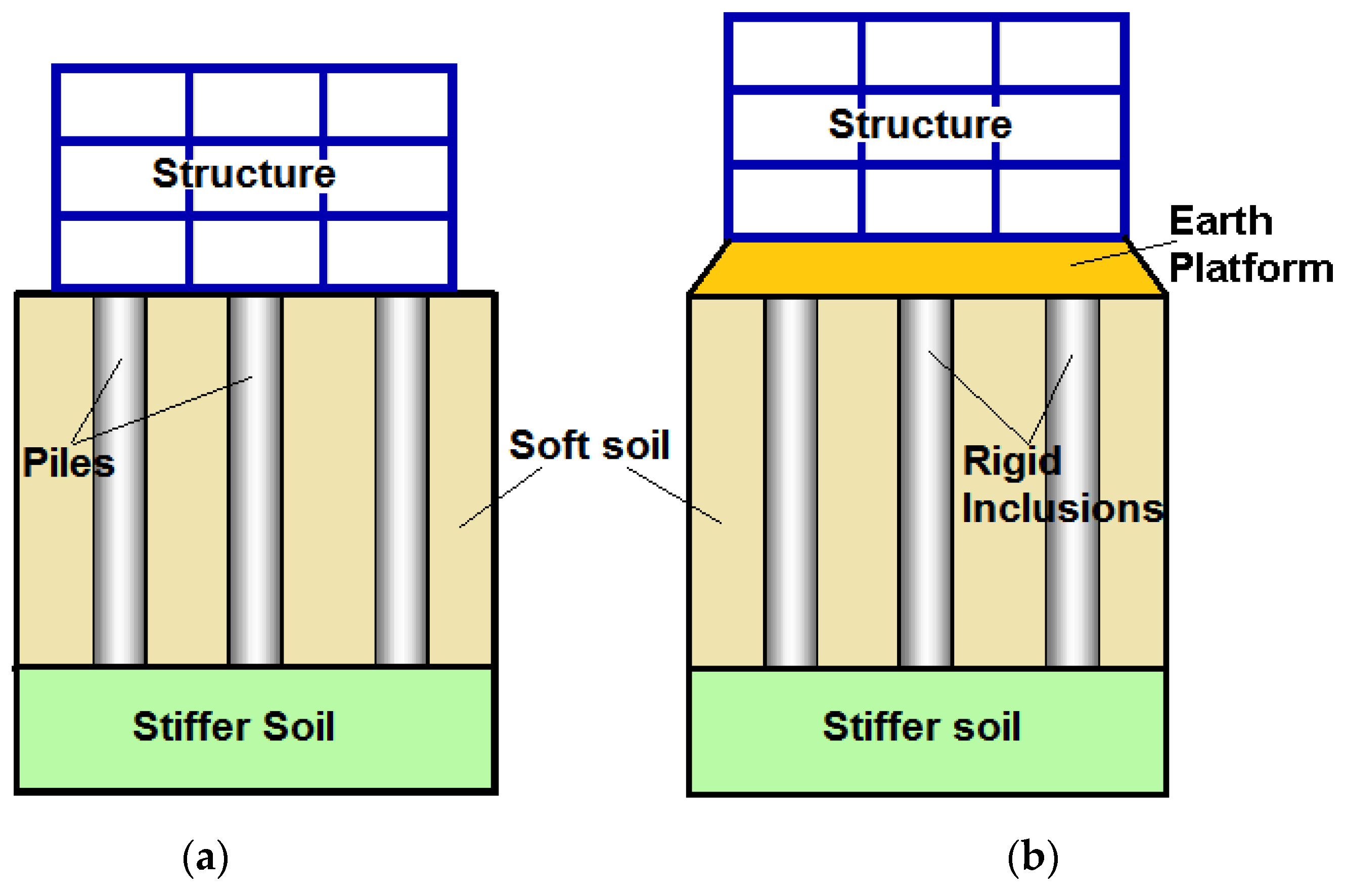
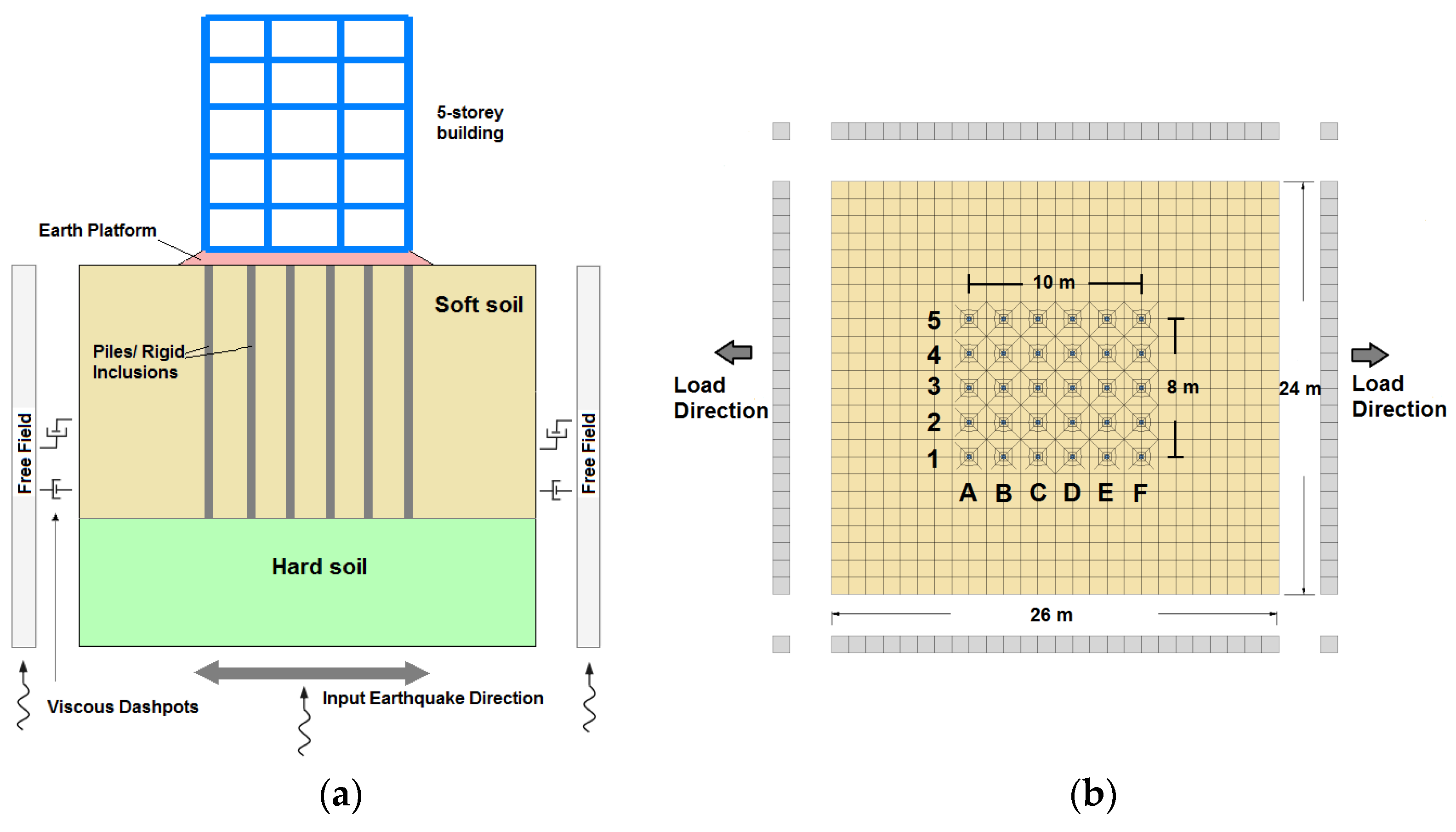
The densification of cities has rarefied the zones with good quality soils and has pushed the construction of buildings in areas with low geotechnical conditions. The use of pile foundations is an efficient alternative to support buildings in the presence of soft soil. The loads from the superstructure are carried through this system and transferred to deeper, stiffer soil layers. However, buildings founded on rigid inclusions have been more recently constructed. This system is similar to the pile system, with the difference that the inclusions are not connected with the slab foundation. An earth platform is set up between them (
Figure 1). In seismic areas, this platform is very functional because it is considered as a zone of energy dissipation. An effective application of both systems implies a reduction in the total and differential settlements in the structure and an increase in the bearing capacity. In a dynamic analysis, the response of these systems is a complex process that relates the inertial interaction between the structure and the foundation and the kinematic interaction between the rigid elements and the soil [
1].
Dealing with simplified geometries, numerous studies solved the soil–pile–structure interaction through systems that adopt the Winkler method and numerical techniques [
2,
3,
4,
5,
6,
7,
8]. However, the use of numerical models becomes a unique alternative solution when the systems are non-linear or have a 3D geometry.
Several researchers investigated the influence of the SSI on the seismic response of buildings supported by piles through two-dimensional models. Carbonari et al. [
9] evaluated the SSI of a coupled wall-frame structure supported by pile foundations subjected to moderate earthquakes through a 2D linear finite element model. The authors concluded that the internal forces in the piles depend on the structure deformability and that the stresses at the deepest sections are caused by the kinematic interaction. Tabatabaiefar et al. [
10] developed a 2D finite difference model to investigate the lateral seismic response of mid-rise building frames under the influence of SSI. The study considered 5-, 10- and 15-storey buildings. Interface elements were considered between the foundation and the soil. The calculation determined that a conventional design procedure that excludes the SSI cannot guarantee the structural safety of mid-rise buildings resting on soft soils. It is due to the amplification of the lateral deflection and the corresponding inter-storey drifts of their flexible base.
Through three-dimensional models, Lu et al. [
11] developed a finite element analysis of a soil–pile–structure system. The adopted structure is a 12-storey, reinforced-concrete-frame building with a single span supported on a group of nine piles. An equivalent linear model is used for soft soil behavior and interface elements are considered at the soil–pile connection. The researchers found that the deflections of the structure are composed by the deformation of the structure itself and the ones caused by the rocking and swaying of the foundation. The distribution of the soil–pile contact pressure is more important in both ends of the vertical reinforcement. Nghiem and Nien-Yin [
12] investigated the seismic response of a 33-storey building through 3D systems. Analyses with rigid and flexible base soils were considered in order to examine the evolution of the SSI effects. The findings showed that the shearing of the flexible base is smaller than the one of the rigid base. Maheshwari and Sarkar [
13] worked on a 3D model of a four-storey portal frame supported in a liquefiable soil. The effects of the intensity of the excitations and the soil stiffness in the system were investigated. The analysis revealed that an increase in the loading intensity augments the effect of nonlinearity on the dynamic stiffness of the soil–pile systems. The effect of linearity is greater in soft soil. Pulikanti and Ramancharla [
14] examined the behavior of pile-supported building frame under transient loading with a 3D finite element model. The study considered the soil–structure interaction with the use of interface elements. The results exposed that the acceleration response of the structure top floor is reduced twice when the interaction between the piles and the soil is considered. Hokmabadi et al. [
15] studied the seismic response of a 15-storey building supported by shallow foundations and a floating piles foundation in soft soil with a 3D numerical model. Shaking table tests were developed to validate the numerical results. The results showed that the lateral displacements of the floating pile foundations are greater than the ones of the structure with a fixed-base condition, but are more reduced than the shallow foundation case due to the rocking components. Badry and Satyam [
16] analyzed the dynamic response of a 3D nonlinear finite element system that consisted of an L-shape 11-storey building supported by a pile foundation with homogeneous soil conditions. The research included the applicability of the equivalent pier methods for the asymmetrical pile groups and the SSI effect of the system. The study pointed out that the displacements in the system response, which considers the soil–structure interaction, are modified to around 15–20% from the fixed-base analysis. The earthquake magnitude and the soil type have an important impact in the response of the SSI system. The effect of an asymmetrical structure shows that the response at all points located at the same level is not the same. Hokmabadi and Fatahi [
17] studied the influence on the seismic performance of a 15-storey building founded on shallow foundations, floating piles and pile-raft foundations. The numerical model was verified with an experimental shaking-table test. The studies determined that the way that shear forces are distributed in the structure depends on the foundation type. The trend and amount of variation of these forces are not the same at each level. The structure supported by shallow foundations experiences more severe rocking compared to the floating and pile-raft foundation due to the presence of piles. However, the base shear forces are higher. With the objective to investigate the influence of the type and of the size of the foundation in the seismic response of midrise buildings, Nguyen et al. [
18] developed a 3D numerical model of a 15-storey moment-resisting frame building supported on end-bearing and floating pile foundations. Interface elements were considered between the soil and the piles. The results displayed that the lateral deflection of the structure is composed of two components: structural distortion and rocking. The load-bearing mechanism alters the shear forces absorbed by the structure and how they are distributed along the pile elements.
Concerning the rigid inclusion, some authors have analyzed systems with this method under dynamic loading [
19,
20,
21]. More recently, and considering building structure, Mánica-Malcom et al. [
22] investigated the seismic response of a 5-storey building with different support conditions in deposits of soft soil in Mexico City. The conclusions indicated that the spectral accelerations are reduced in the system that considers the structure supported by inclusions. Rocking motions produce axial force increments in the rigid elements. López Jiménez et al. [
23] explored the seismic response of three-dimensional models of 3-storey reinforced buildings supported by piles and rigid inclusions in liquefiable soil. Different soil profiles and frequency excitation were considered. The results showed that the type of failure in the pile (buckling or bending) is determined by the thickness of the liquefiable soil, the frequency of earthquakes and the pile boundary conditions.
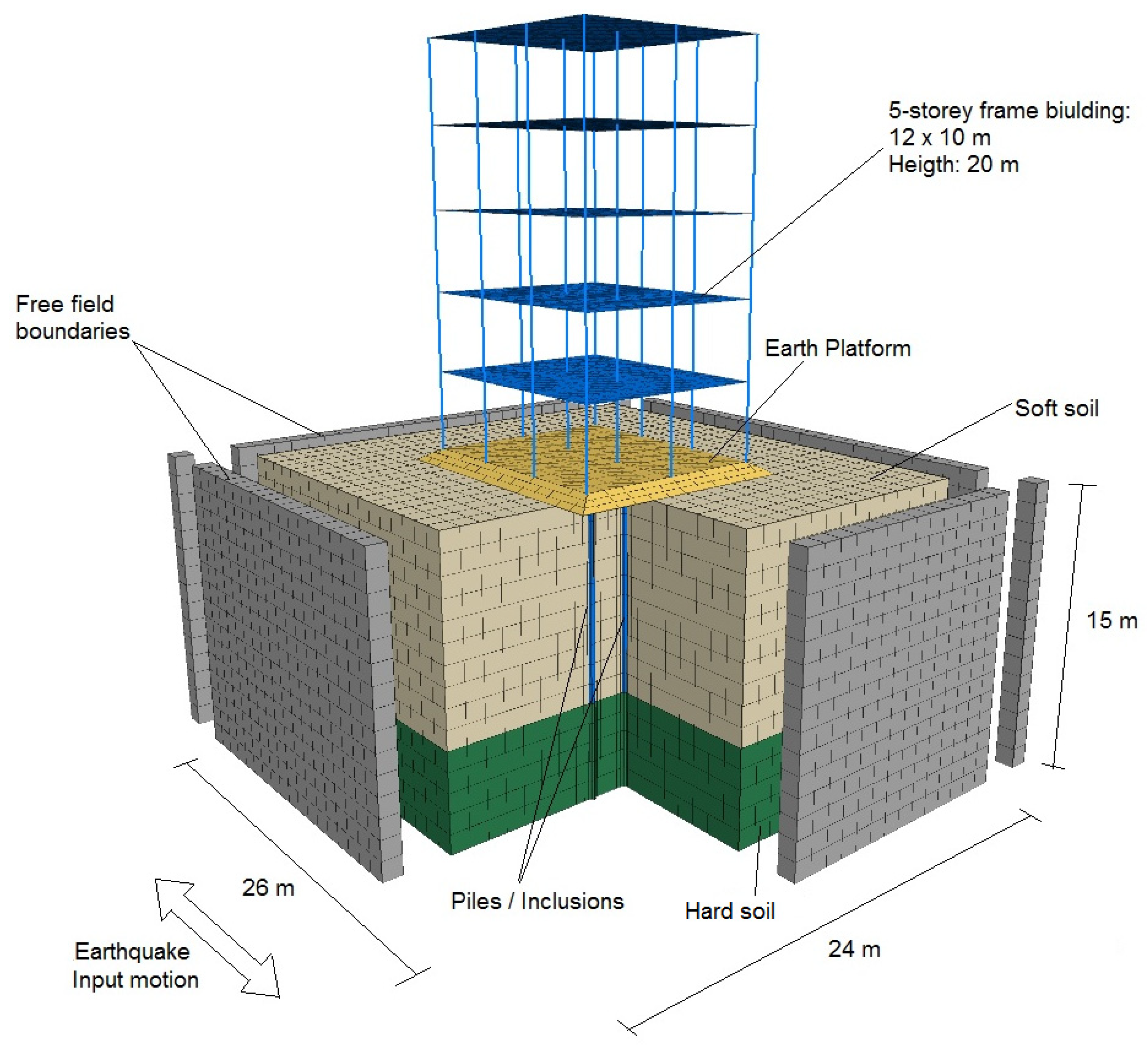
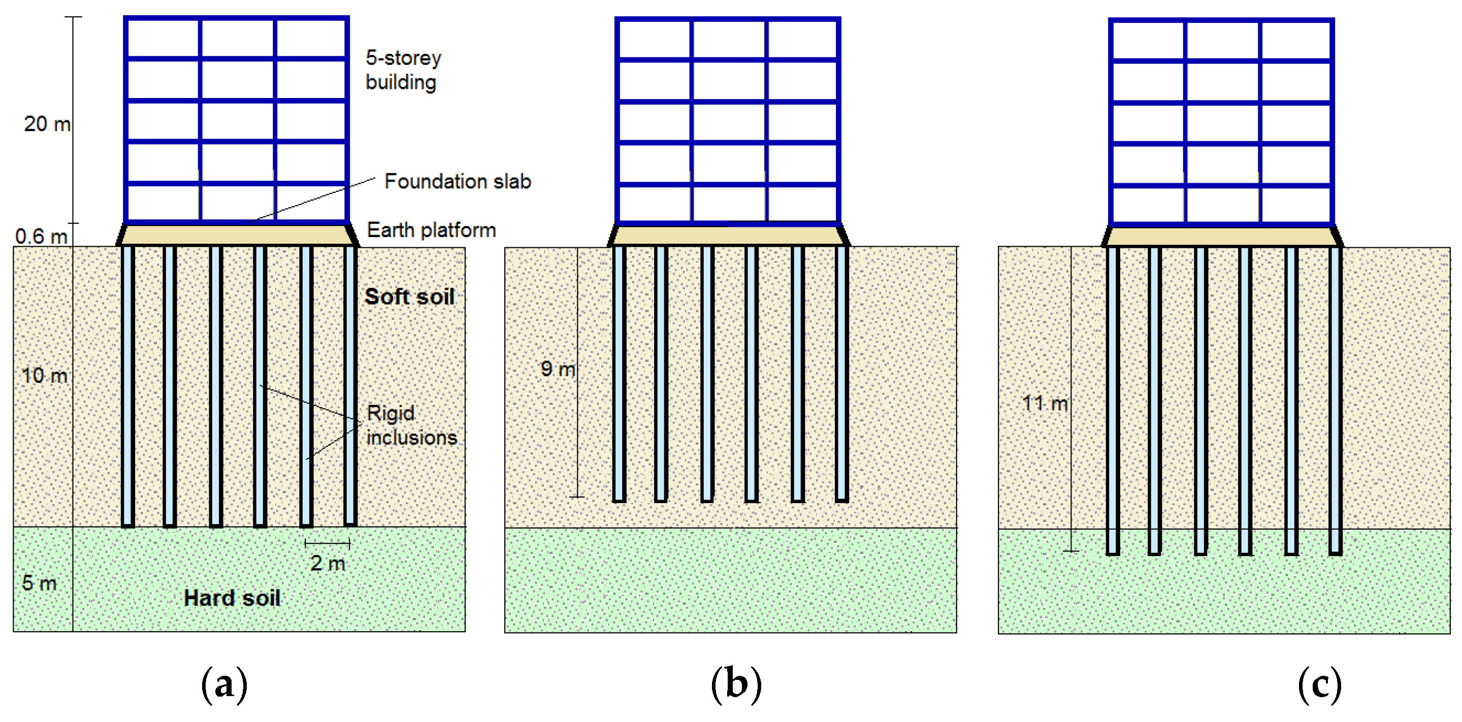
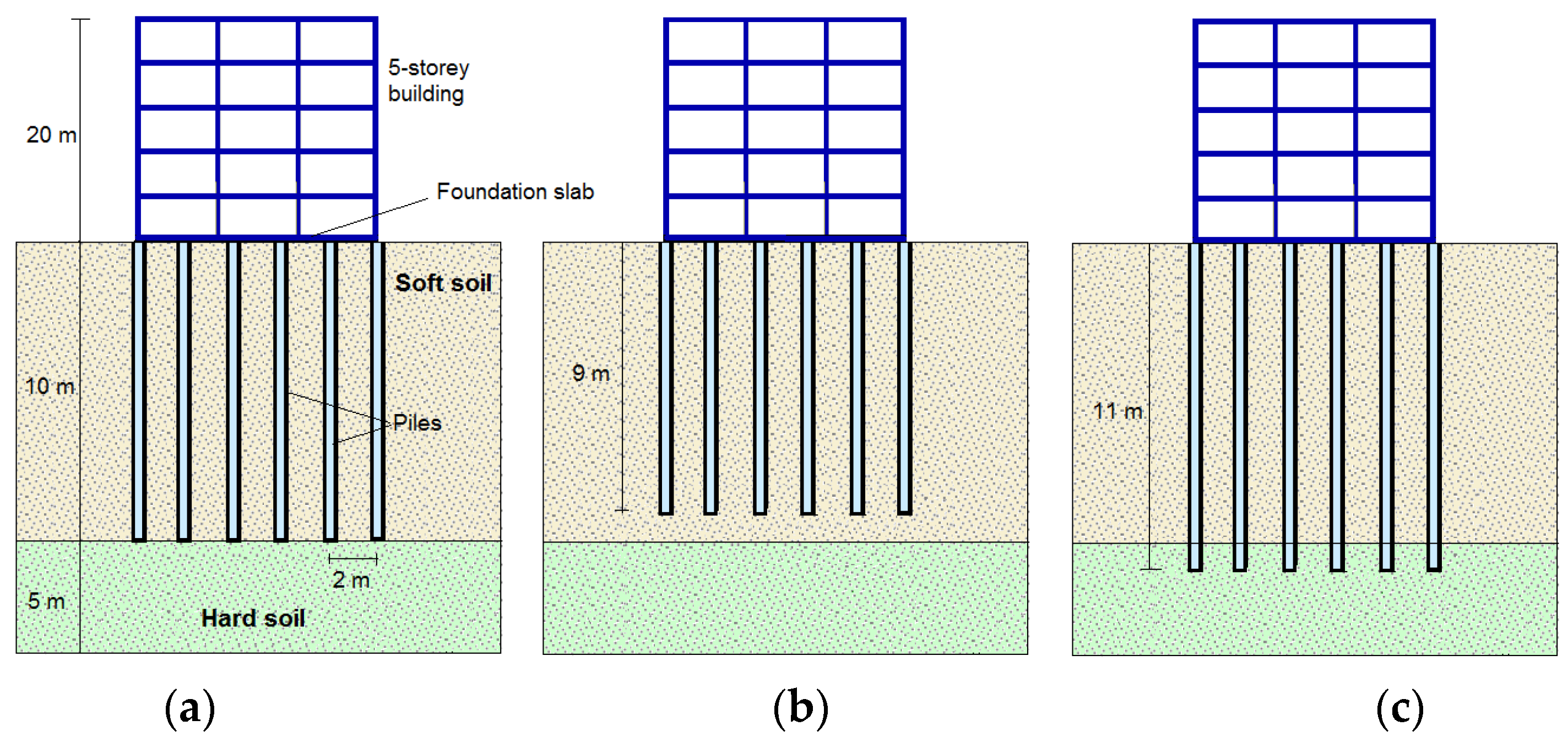
Considering the above literature, the main objective of this paper is investigating the impact of the different support pile toe conditions (including the placement on hard soil, an anchorage and floating piles) on the response of mid-rise buildings. Although the behavior of foundations and superstructures are closely related, in practical engineering, they typically are modeled independently. A substructure technique is also usually applied to the foundation system itself, whereby the behavior of the foundation slab and piles are considered separately. For this reason, in this paper, fully coupled soil–pile–superstructure numerical models are developed to cover many uncertainties (geometrical complexity, connection between elements and material properties) involved in pile systems to obtain reliable results without incurring excessive time calculations. These kinds of calculations allow to obtain (a) qualitative data identifying important zones where damage or failure are likely to occur and key aspects in the response of the pile elements and superstructures; and (b) quantitative data (controlled by the limitations of the model characteristics and imposed conditions) to provide conclusions and recommendations to be applied in future engineering projects. Soil–inclusion–platform–structure systems are also analyzed to be compared with pile systems. To achieve this goal, fully coupled three-dimensional analyses of both systems were developed using the finite difference software Flac 3D. The effect of the structure’s dynamic characteristics on the response of the analyzed systems is studied considering 3, 5 and 7-storey building frames. The linear elastic perfectly plastic constitutive model, with a Mohr–Coulomb failure criterion, is used to represent the soil behavior. The results are presented in terms of maximum lateral displacements, inter-storey drifts and shear forces in the buildings. The values of the rocking of the foundation are also obtained. Concerning the foundation elements, normal forces, bending moments and displacements are compared for the different support conditions in the systems.
2. Materials and Methods
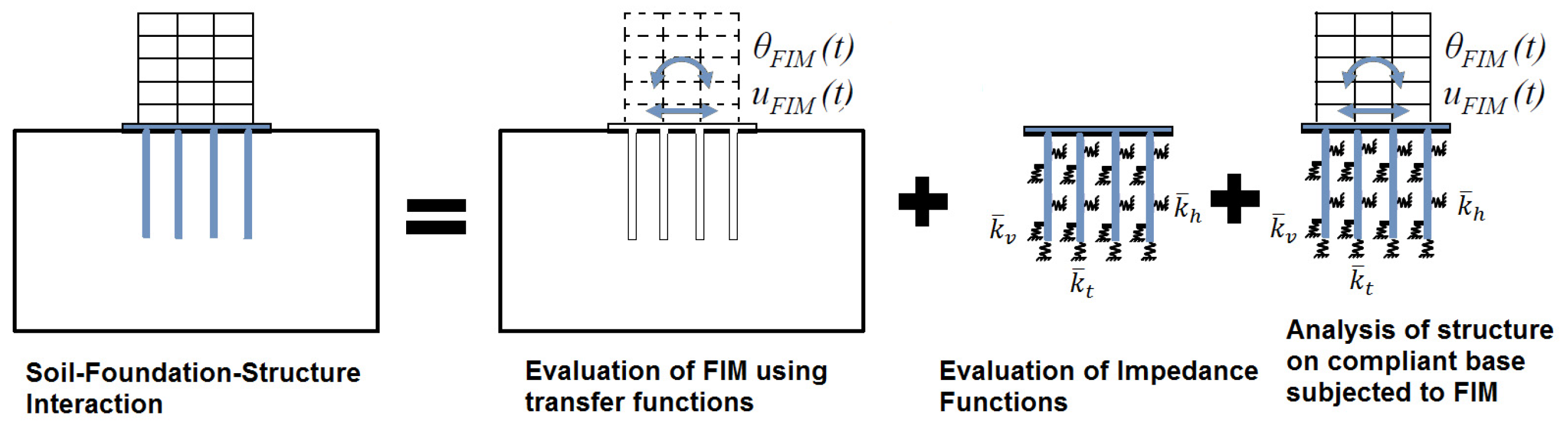
The substructure and the direct method are two different ways to evaluate the soil–structure interaction. In the substructure method, the soil–pile-structure system is separated into near-field and far-field cases. The near-field case simulates the soil–pile–structure interaction, while the far-field accounts for semi-infinite nature of the soil medium for the site response analysis. The superposition of this approach requires an assumption of linear soil and structural behavior [
24]. For the use of this method, three steps are necessary: (1) the evaluation of a Foundation Input Motion (FIM), which is the motion that would occur on the foundation slab if the structure and foundation had no mass; (2) the determination of the impedance function (stiffness and damping characteristics of the foundation–soil system); and (3) the dynamic analysis of the structure supported by a compliant base represented the impedance functions and is subjected to a base excitation consisting of the FIM. These steps are represented in
Figure 2.
With the substructure approach, Wotherspoon and Pender [
25] evaluated the response of a 10-storey, the single-framed structure supported by a pile foundation under dynamic load. The nonlinear behavior of the structure and of the piles was taken in to account. The Winkler springs approach with a non-linear behavior was used to represent the interface elements in the soil–pile. Di Laora et al. [
26] carried out the analysis of a tall building in Naples (Italy) that has recently undergone a seismic vulnerability assessment according to the code requirements. The building is 100 m high and is founded in a piled raft floating in a soft soil. They used the substructure method to get the kinematic and inertial effects of the system.
On the other hand, the direct method allows modeling the entire soil–foundation–structure system. This method is able to simultaneously consider with accuracy the behavior of both the soil and the structure. Several researchers [
11,
12,
16,
17,
22,
27,
28,
29] have studied the effect of the soil–pile–structure interaction on the behavior of buildings, adopting the direct method to get realistic analysis. In this study, the direct method is employed because of its adaptability to deal with complex geometries and material properties.
6. Results and Comparison
The results are presented in this section in terms of the response spectrum of the different systems, lateral displacements, inter-storey drifts and shear forces in each building level, as well as the rocking of the foundation. All these values are the maximum values recorded during the loading. In order to check the influence of the earthquake on the response of the building, the efforts and displacements at the initial state were subtracted from the obtained values. For the piles and rigid inclusions, normal and shear forces, bending moments and displacements are presented.
6.1. Effect of the SSI in the Analyzed Systems
In a soil–foundation–structure system, the soil deformation is the result of the incident seismic waves during an earthquake event. This movement is transferred to the structure generating inertial forces that cause stresses at the foundation, which, in turn, are propagated to the supporting soil. The properties of the soil deposits have a considerable influence on the earthquake motions experienced at the base of the superstructure. These effects are a function of the mechanical and geometrical characteristics of the subsoil and of the earthquake motions at its base.
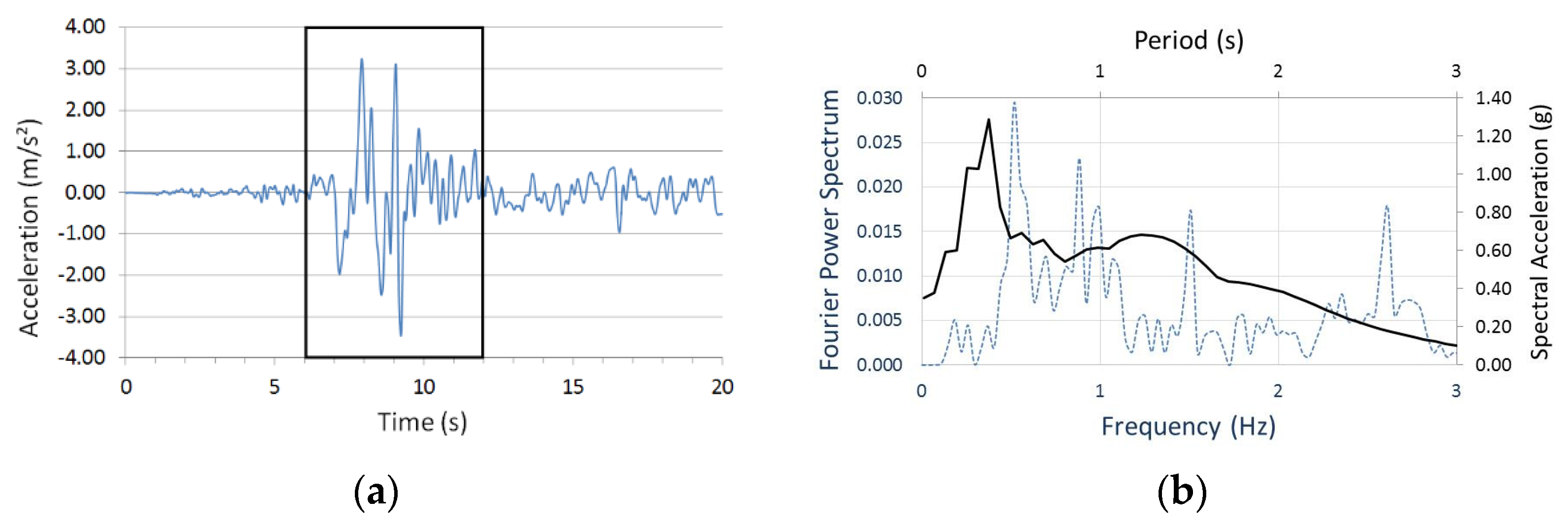
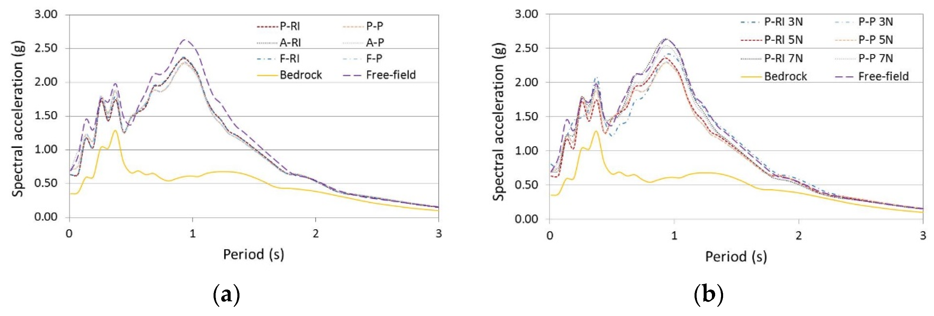
With the purpose to examine the influence of the SSI effects in the analyzed systems, the acceleration response spectrum of the motions recorded at the surface of the soil (base of the structure) are shown in
Figure 9. The Fast Fourier Transform was used to calculate the acceleration response spectrum. These spectrums describe the maximum response of a single degree of freedom system for a specified earthquake ground motion and 5% of damping. For all the considered surface-response spectrums, the soil fundamental period and the spectral acceleration increase. This can be significant in the superstructure response when the period of the ground motion matches the fundamental period of the building, as it occurred in the 1985 Mexico City earthquake [
56].
Figure 9a illustrates the response spectrum of the systems with a 5-storey building with placed, floating and anchored vertical reinforcements. The response spectrum of the systems with vertical reinforcements is smaller than the free-field motion one. The response of both the rigid inclusion and the pile systems are independent of the support condition. However, the response of the piles is lower than the one of the rigid inclusion systems. This is due to the inertial interaction of the complete system and of the piles’ kinematic interaction. In the case of rigid inclusions, the response spectrum was established with the surface acceleration recorded at the top of the earth platform. The acceleration at the top of the soft soil was a little greater. This highlights the advantage of the earth platform, which dissipates energy and then reduces the inertial forces in the buildings in seismic sites.
Comparing the response spectrum for the P-RI and P-P systems in
Figure 9b, it is highlighted that the response of the rigid inclusion and that of the pile systems with the 7-storey building induces a higher amplitude (similar to the free field case) than the systems with 3- and 5-storey buildings. A greater motion is produced at the base of the building due to the inertial forces. The spectral accelerations values in the systems with the 3- and 5-storey buildings are close in all cases; only the P-RI 3N (rigid inclusion system placed on the hard soil with the 3-storey building) is different and presents a small amplification and reduction in some range periods.
6.2. Shear Forces in the Superstructure
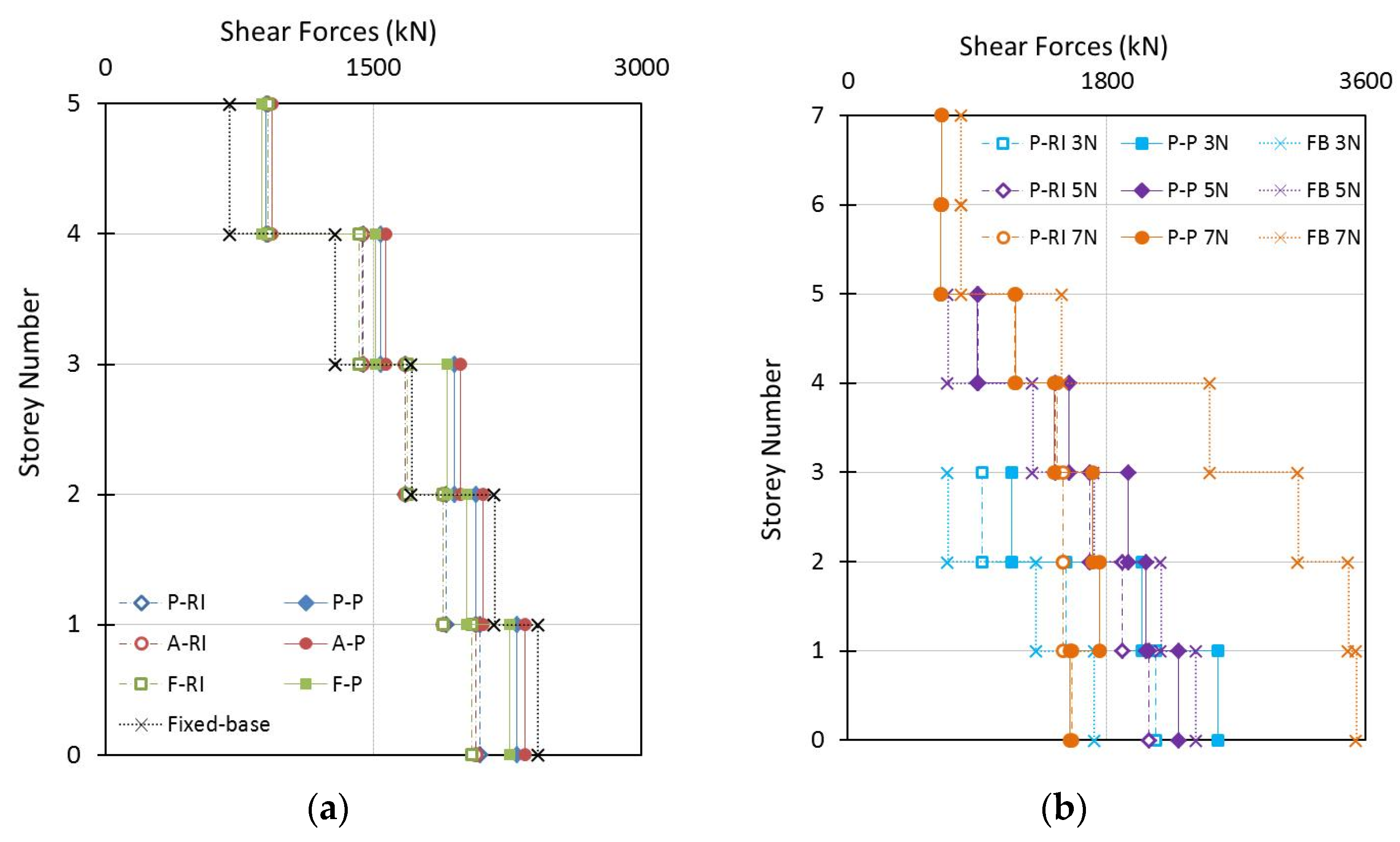
The impact of the SSI on the shear forces of the 5-storey building system is presented in
Figure 10a. During the time history analysis, the shear forces generated in every column in each level were summed up in order to determine the maximum shear force in that level. Then, the absolute maximum value of the shear force in each level is registered. Consider that the SSI reduces the base shear forces compared to the fixed-base case. The maximum base shear force of the fixed-base condition is equal to 2423 kN. This value decreases by 3%, 5% and 7% for the A-P, P-P and F-P systems, respectively. Concerning the A-RI, P-RI and F-RI, the decreases are equal to, respectively, 14%, 13% and 15%.
The shear forces along the building with pile cases are greater than with the rigid inclusion systems at all levels. The fixed connection of the pile head and the foundation slab increase the inertial forces. However, this difference is reduced in the upper levels. For instance, the A-P case gives shear forces higher than 13%, 18% and 2% compared to the A-RI system in the first, third, and fifth levels, respectively (
Figure 10a). The distribution and the value of the shear forces differ with the level number of the building [
17,
18]. For both the pile and rigid inclusion systems with the 5-storey building, the anchored systems induce higher shear forces than the placed and floating pile systems. The rigid elements absorb the inertial forces from the toe (connection of the element on the hard soil), while the floating systems exhibit lower shear force values.
As expected, the shear force values in the fixed-base case with the 7-storey building (FB 7N) are greater than the ones of the fixed-base cases with the 3- and 5-storey buildings. The three systems present a similar spectral acceleration with different building mass and height (
Figure 10b). The base shear forces of the P-RI 7N are 56% smaller than the FB 7N case (3538 kN). For the P-P 7N, this difference is the same. The base shear forces in the P-RI 3N and P-P 3N systems are equal to, respectively, 2139 kN and 2574 kN. It corresponds to an increase of 24% and 50% with respect to the fixed-base condition. However, considering the SSI, the shear forces of both the pile and rigid inclusion systems with the 3- and 5-storey buildings are greater than the ones of the 7-storey building case. The fundamental period of the systems with the 3- and 5-storey buildings lies in a response spectrum region where the acceleration is close to the resonance. It is not the case for the 7-storey building.
6.3. Rocking of Foundations
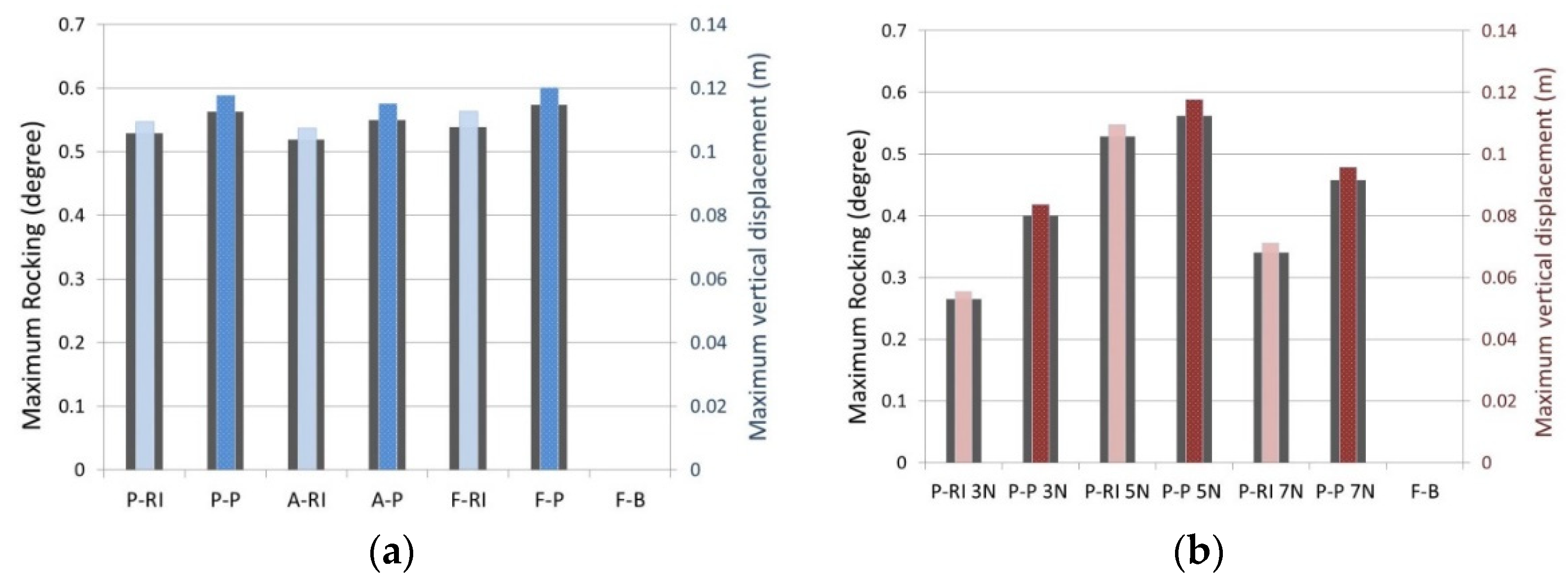
During strong seismic excitations, rocking takes place due to the generated inertial forces in the superstructure, which cause compressions on one side (settlements) and tensions (uplifts) on the other side of the foundation.
The rocking can affect the stability of the building due to the lateral displacement increase. On the other hand, some of the seismic energy can be dissipated due to the rocking dissipation, which reduces the shear forces in the structure. The amount of rocking depends on the foundation type supporting the superstructure. When placed or anchored on the hard soil, the axial deformation of the elements and the deformation of the surrounding soil are the main factors that can cause rocking. Additionally, when the system is composed of floating reinforcements, the settlements are also significant. There is no rocking in the fixed-base structure (F-B).
Figure 11a displays the maximum rocking in the systems with the 5-storey building. In general, the rocking values in the rigid inclusions cases are lower than in the pile systems with the same type of support. The inertial forces acting in these systems are lower, and due to the presence of the earth platform, it reduces the total and differential settlements. The maximum rocking values in the P-RI, A-RI and F-RI systems are 0.52°, 0.51° and 0.53°, respectively. In the pile cases, these values are equal to 0.56°, 0.55° and 0.57° for the P-P, A-P and F-P cases, respectively. It can be noted that the systems with placed and anchored elements induce a lower rocking compared to the floating systems The connection with hard soil reduces the foundation uplift and the settlement values when the compression forces act on the other side of the foundation.
In
Figure 11b, the rocking values in the P-RI and P-P systems are compared with the 3-, 5- and 7-storey buildings. According to the inertial forces developed in the building, the maximum rocking is presented in the systems with the 5-storey building. P-RI 5N is 99% and 56% greater than P-RI 3N and P-RI 7N. The same comparison, but with piles, gives increments equal to 40% and 22% respectively.
6.4. Lateral Displacement and Inter-Storey Drifts
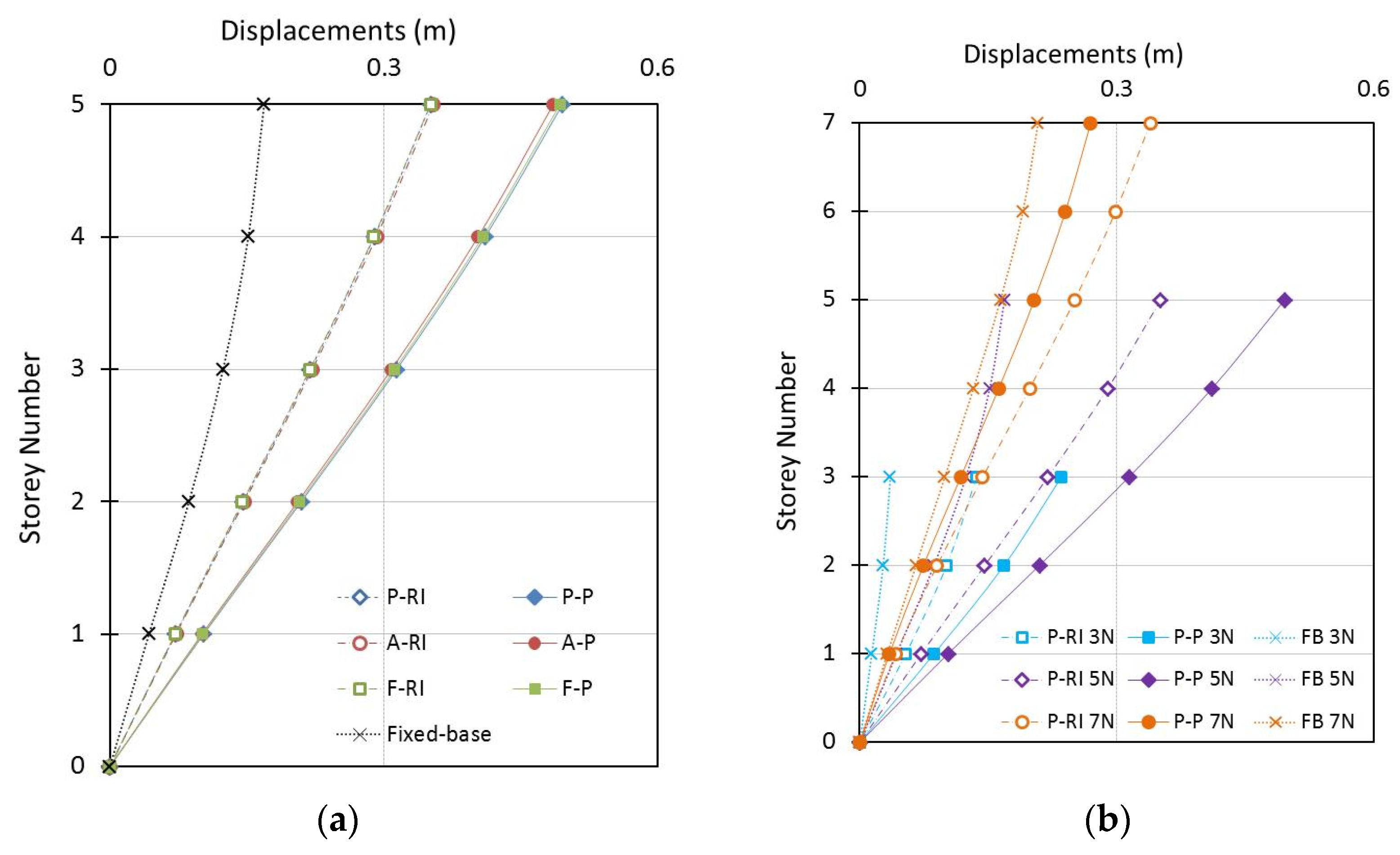
The displacements of the analyzed systems that consider the SSI were amplified compared to the fixed-base condition. This is due to the translation (directly related to the shear forces generated in the building) and to the rotation of the foundation system. Due to these displacements increment, the structure has to be more ductile to undergo these larger deformations without collapsing. In order to have a reasonable pattern of deformation, the values reported in this study correspond to the displacement at each level when the maximum displacement occurred at the top level. The displacements of the foundation are subtracted from the storey displacements, which means that the values are referred to the translation of the foundation at the surface level. The translation at the base of the structure in the rigid inclusions cases is equal to 0.24 m and 0.06 m for the pile cases.
Figure 12a shows that the maximum displacement at the top level of the rigid inclusion systems with the 5-storey building is almost equal (0.35 m) with any support type. This value denotes an increase of 118% compared to the fixed-base condition. When the 5-storey building is founded with the F-P system, the maximum lateral deformation reached is 0.49 m, which corresponds to an increase of 40% compared to the rigid inclusion systems.
In accordance with the shear forces developed in the superstructure and the rocking values in the different systems, it can be noticed from
Figure 12b, that the maximum displacement in the top level of the P-RI 5N case is higher, at 169% and 6%, with respect to the P-RI 3N and P-RI 7N cases, respectively. In the pile systems, the P-P 3N and P-P 7N cases are 53% and 47% smaller than the P-P 5N one.
The ratio of the successive floor displacement difference to the height of the floor is known as the inter-storey drift. This quantity is an important engineering response and an indicator of the performance of the buildings because most of the seismic design codes establish limits to these values. Besides, this is an important indicator of the structural behavior in performance-based seismic analysis. In this study, the maximum recorded inter-storey drift in the rigid inclusion systems with the 5-storey building is equal to 1.87% and is independent of the support type. In the pile foundation cases, the maximum inter-storey drift (2.66%) is obtained in the P-P 5N case. The maximum inter-storey drift in the P-RI 3N and P-P 3N cases are 1.34% and 2.16%, respectively (
Figure 12b). For the P-RI 7N and P-P 7N cases, the corresponding values are 1.36% and 1.10%.
6.5. Efforts and Displacements in Vertical Reinforcement Elements
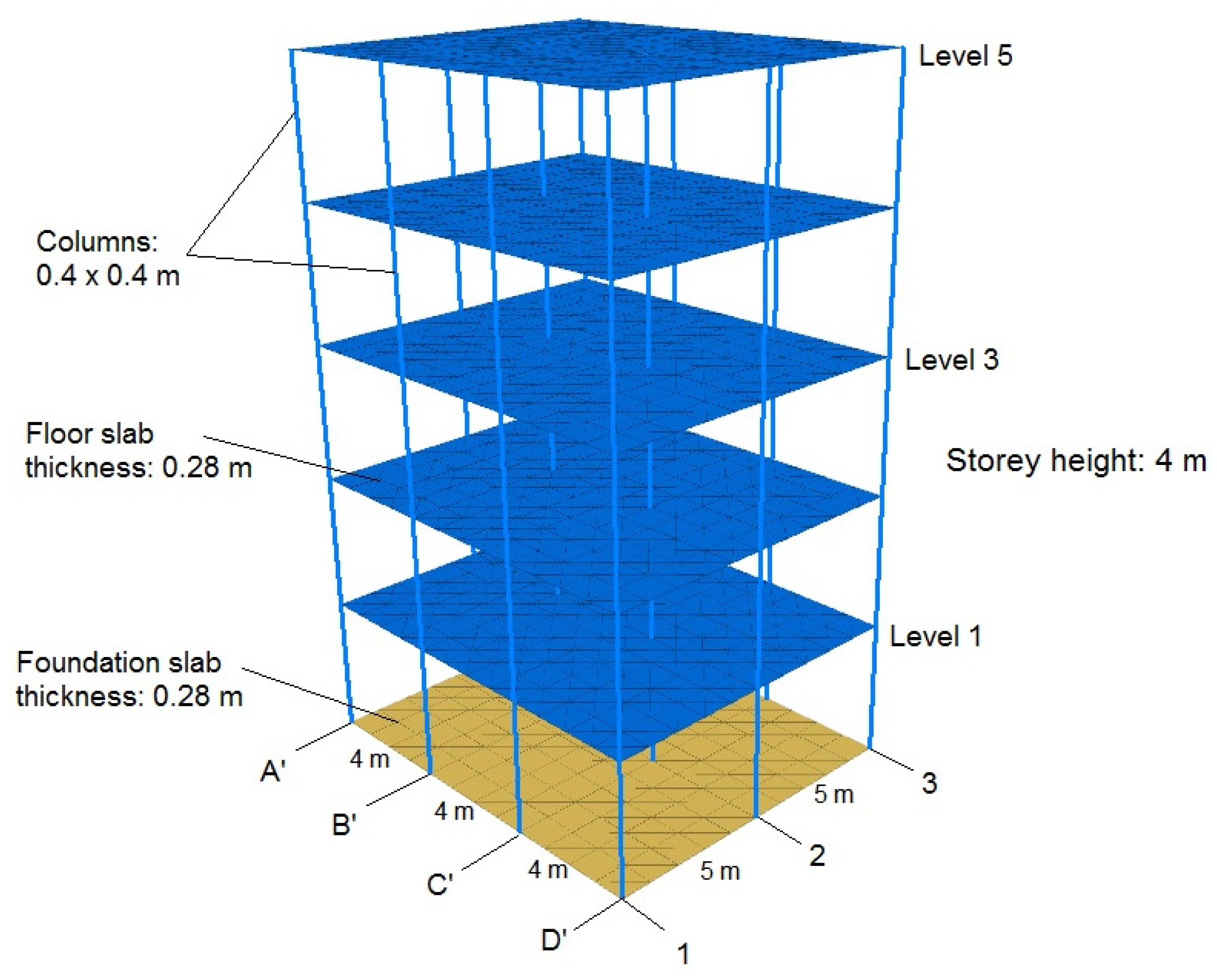
The results obtained in the rigid elements are presented in terms of normal and shear forces, bending moments and displacements for all cases. The displayed results correspond to the elements located on the edges of Axis 3, where the maximum efforts and displacements take place. For the location of the vertical reinforcements, a plan view of the system is presented in
Figure 5.
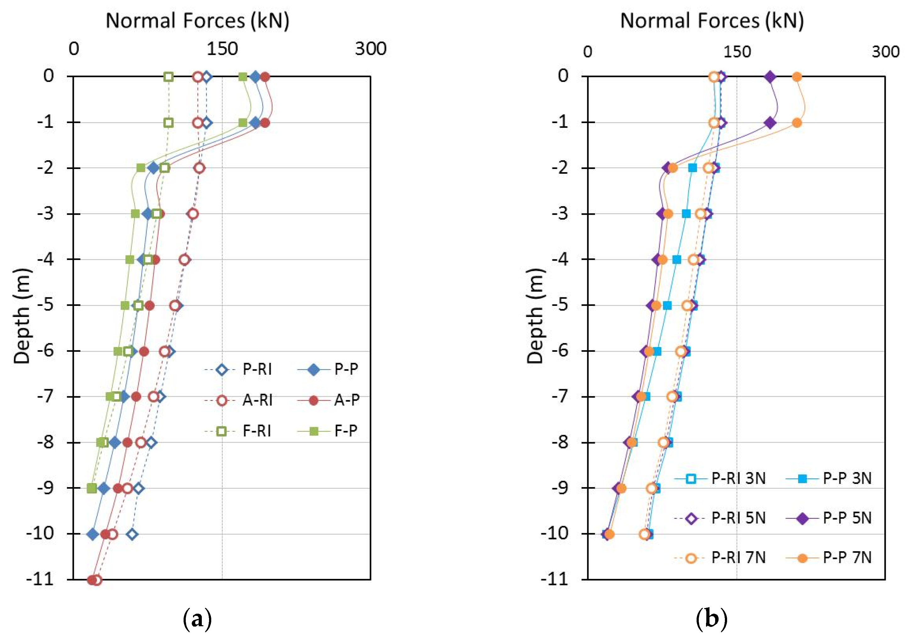
6.5.1. Normal Forces
The maximum normal forces are reached in the head of the rigid elements and decrease with depth in all the analyzed cases. The values at the head in A-RI, P-RI and F-RI systems with the 5-storey building are equal to 125 kN, 133 kN and 96 kN, respectively (
Figure 13a). The normal forces along the elements in the A-RI and P-RI systems are similar. However, these values are 56% greater than in the F-RI case. This difference is due to the fact that there is no contact of the elements with the hard soil.
In the A-P, P-P and F-P systems, the maximum normal forces are increased by 54%, 37% and 83% with respect to the rigid inclusion systems with the same support type. This increase is due to the higher compression and tension forces (increased by the inertial forces in the building) in the piles at the link with the slab foundation. In the rigid inclusion systems, these values are not modified by the existence of the earth platform between the piles and the foundation slab. The normal forces in the pile systems are reduced at 2 m of depth with respect to the head value.
Figure 13b shows that the normal force values in the head (133 kN) and along the rigid inclusions are not influenced by the different building heights. In the pile cases, the P-P 7N one is the system with higher normal forces at the pile head (210 kN). This value decreases, respectively, with 12% and 40% compared to the P-P 5N and to the P-P 3N cases. This is due to the weight difference of the buildings.
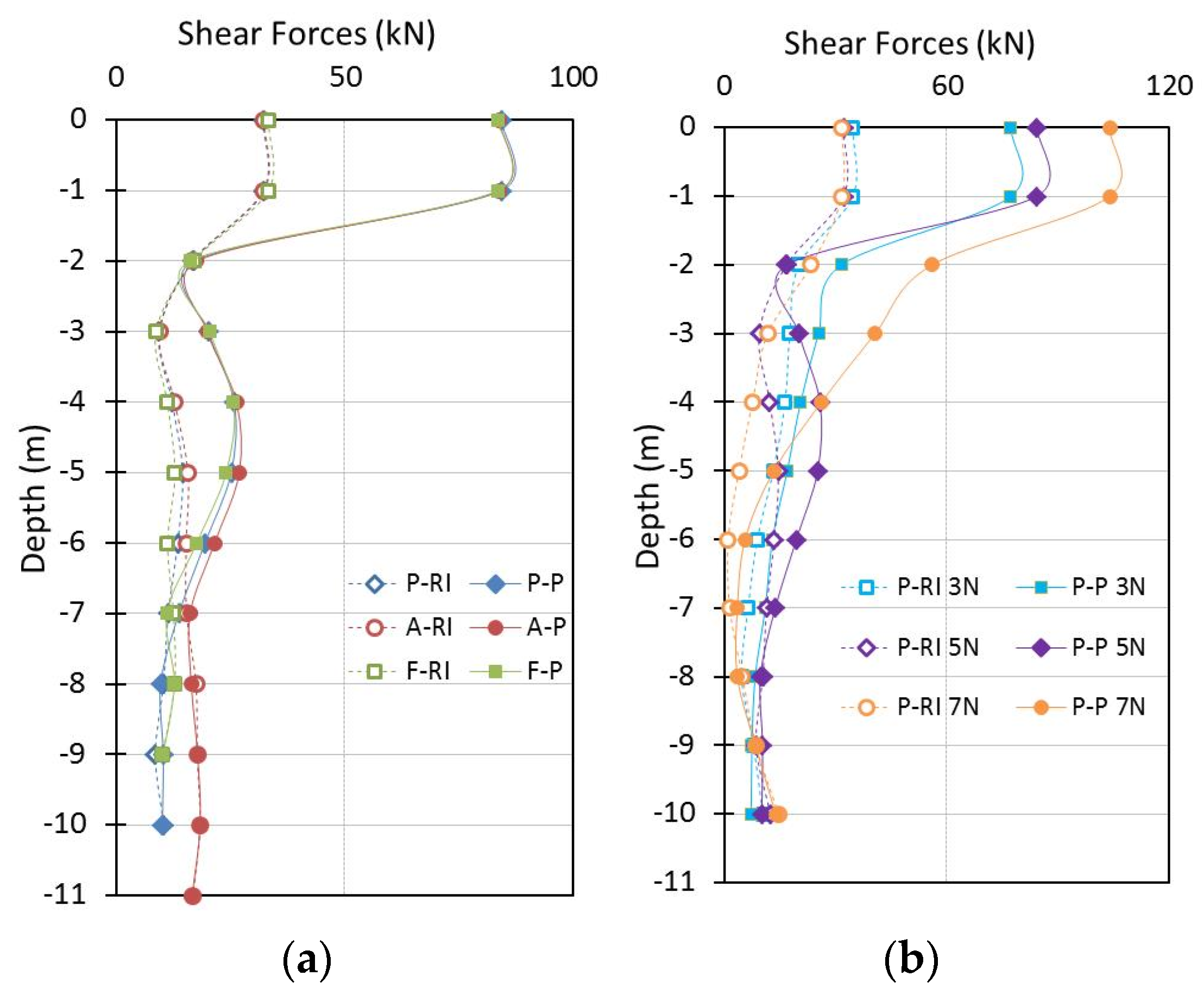
6.5.2. Shear Forces and Bending Moments
The maximum shear forces and bending moments in the rigid elements for the systems with the 5-storey building are presented in
Figure 14a and
Figure 15a, respectively. In the rigid inclusion cases, the maximum shear force value reached is equal to 33 kN in the head of the element and until 1 m of depth independently of the support condition. The bending moment at this level is null. However, the maximum bending moment reached is 50 kN.m at 3 m of depth for all types of support. Along the rigid inclusions, the shear force values vary from 15 kN at 2 m to 10 kN at 9 m of depth. In the A-RI case, the shear force and bending moment increase at the toe level and reach a value of 17 kN and 23 kN.m, respectively. The values at this level are due to the lateral deformations of the surrounding soil in the elements (kinematic forces). The use of floating or placed reinforcements on the hard soil systems allow reducing the shear forces at the anchorage level.
In the pile cases, the maximum shear forces are also located at the pile head with a value of 84 kN, which means an increment of 154% with respect to the rigid inclusion cases. The maximum bending moment value reached is equal to 145 kN.m. This is due to the rigid connection with the foundation slab, which amplifies the inertial forces at this level. For the rigid inclusion improvement, the earth platform permits to decrease the efforts in the head of the reinforcements. This highlights the advantage to use this technique in seismic areas. The shear forces along the pile cases are greater than in the rigid inclusion systems from 2 m to 9 m of depth. As in the rigid inclusion cases, the shear forces in the anchored system are increased 80% compared to the floating and placed ones at the anchorage level. The moment reached at this level in the A-P is equal to 16 kN.m.
The comparison of shear forces in the P-RI and P-P systems with the 3, 5, and 7-storey buildings is illustrated in
Figure 14b. The maximum shear force value at the head and at the toe of the rigid inclusion systems is almost the same for the three building heights. However, the shear forces in the P-RI 7N system are lower at the middle depth of the rigid elements compared to the P-RI 3N and P-RI 5N cases. The values in P-P 5N are 9% bigger than P-P 3N but 18% smaller than P-P 7N.
The maximum moment (
Figure 15b, always located at 3 m depth) of the P-RI 3N is equal to 70 kN, which corresponds to an increase of 13% and 42% compared to the P-RI 7N and P-RI 5N cases. The maximum bending moments at the connection with the slab are equal to 149, 145 and 114 kN.m for P-P 7N, P-P 5N and P-P 3N, respectively. The maximum shear forces and bending moments in the inclusion and pile cases strongly depend on the dynamic characteristics of the buildings.
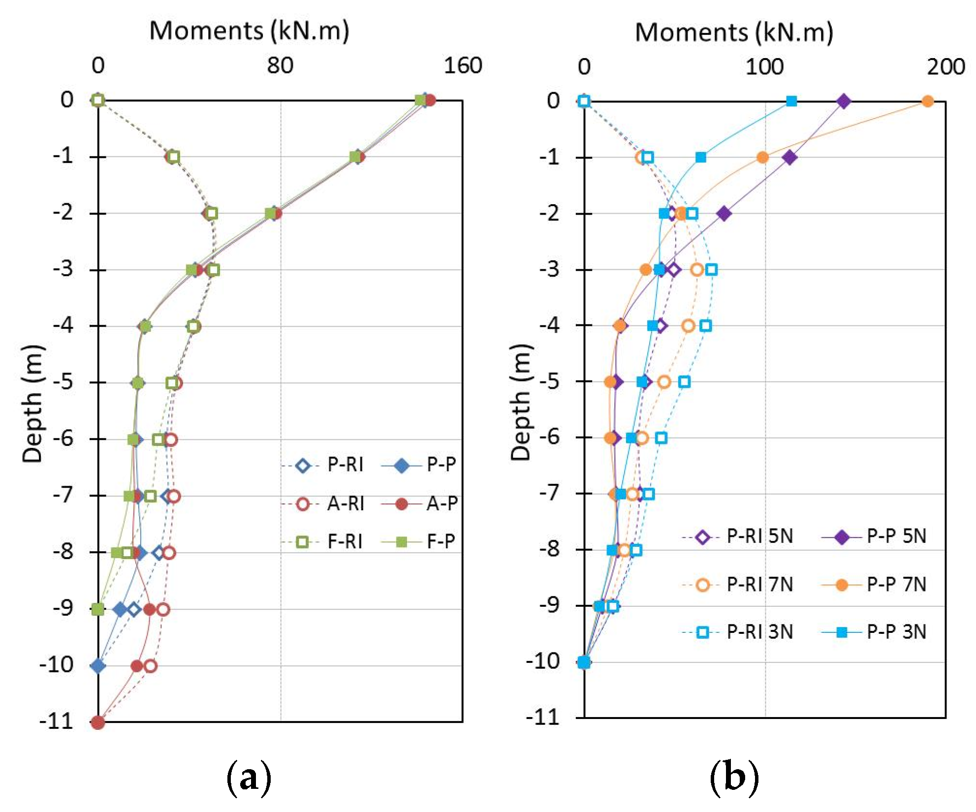
6.5.3. Displacements
Figure 16a indicates that the displacements of the rigid inclusions and that of the piles systems are not influenced by the support condition. The maximum displacement occurs at the head of the vertical elements. The maximum displacement in the rigid inclusions system is equal to 0.39 m. In the piles, this value reaches 0.35 m, which implies a reduction of 10% compared to the rigid inclusions. The displacement in the pile toe for all systems is almost the same (0.27 m).
Figure 16b shows that the rigid elements in the P-RI 3N system present the greater displacement at the head of the elements (0.44 m). This value decreases by 11% and 15% for the P-RI 5N and P-RI 7N systems, respectively. In the case of piles, the maximum displacement is 0.37 m in the P-P 3N system.
7. Conclusions
Fully coupled three-dimensional analyses of both the soil–inclusion–platform–structure and soil–pile–structure systems were developed with different foundation types under seismic loading. Floating, placed and anchored on hard soil rigid elements were considered. The linear elastic perfectly plastic constitutive model with a Mohr–Coulomb failure criterion was used to model the soil behavior. Here, 3-, 5- and 7-storey buildings were implemented to investigate the dynamic characteristics of the superstructure influence on the response of the systems. Interesting qualitative and quantitative data on the foundations and building responses were obtained from the calculations. The numerical results allow providing the following conclusions that can be applied in other engineering studies considering the limitations of the adopted modeling and of the imposed conditions. It is also important to highlight that in order to completely validate the obtained numerical results, experimental studies are necessary.
The fundamental period and the spectral acceleration in the soil surface response spectrum were increased in all analyzed cases.
The shear forces along the building with pile foundations were greater than the ones for the rigid inclusion systems. This is due to the fixed connection at the pile head and foundation slab that increases the inertial forces in the structure. Considering the SSI, the shear forces of both the pile and rigid inclusion systems with 3- and 5-storey buildings are greater than the ones of the 7-storey building case. The fundamental period of the systems with the 3- and 5-storey buildings lies in a response spectrum region where the acceleration is higher (close to the resonance) than the 7-storey building.
The systems with placed or anchored elements induce lower rocking compared to the floating system. The connection with the hard soil reduces the uplift on one side of the foundation and reduces the settlement values when the compression forces act on the other side of the foundation.
The displacements and inter-storey drifts when considering the SSI are amplified compared to the fixed-base case. The maximum displacement at the top level of the rigid inclusion and pile systems with the 5-storey building is almost equal to any type of support.
In the systems with the 5-storey building, the maximum normal forces in the piles systems are greater than in the rigid inclusion systems. This increase is due to the high compression and tension forces in the piles at the connection with the slab foundation.
The maximum shear forces are more important at the rigid inclusions heads and decrease with the depth. The maximum bending moment is reached at 3 m of depth and is null at the head. Because of the connection with the foundation slab, in the pile cases, the bending moments and the shear forces at the pile head are great regardless of the type of support. The rigid inclusion technique allows reducing these efforts at the head. It represents an advantage in seismic areas. The anchored systems induce an increase in the moments and of the shear forces compared to the floating and placed on hard soil cases. This is due to the extra kinematic ground forces in deeper areas. This important factor should be considered in the design of the rigid element to avoid failures at this level.


