Article

Modeling and Evaluation of a Dynamic Channel Selection Framework for Multi-Channel Operation in ITS-G5

Department of Networked Systems and Services, Faculty of Electrical Engineering and Informatics, Budapest University of Technology and Economics, Műegyetem rkp. 3., H-1111 Budapest, Hungary
*
Author to whom correspondence should be addressed.
Telecom 2023, 4(2), 313-333; https://doi.org/10.3390/telecom4020019
Submission received: 5 May 2023 / Revised: 8 June 2023 / Accepted: 14 June 2023 / Published: 19 June 2023

Abstract

:
Many years ago, it seemed inconceivable that our cars could drive autonomously or communicate with each other to form a self-organizing convoy or platoon. By 2023, however, technological advances have taken us to the point where most of these goals will be achieved. In the time of what was initially known as Day 1, single-channel Intelligent Transport System (ITS) devices fully met the requirements for safe communication. The trends show that with the rapid development and the emergence of new, more robust Vehicle-to-Everything (V2X) applications, which require higher bandwidth (collectively called Day 2), the current single-channel medium access method in the available ITS bands will no longer achieve the desired capacities. The main reason is that Day 2 and beyond V2X information dissemination protocols introduce increasing packet sizes and sending frequencies. To complete a resource-friendly and more efficient operation with Day 2 or other advanced V2X services, ITS standards present the Multi-Channel Operation (MCO) constellation as a potential solution. In the case of MCO, we use two or more channels simultaneously, thus preventing the radio medium from saturating its capacity. However, there are still several pending questions about MCO applicability, practical usage, configuration, and deployment, to name a few. The primary purpose of this article is to present a dynamic channel selection framework design and implementation capable of modeling and simulating advanced multi-channel communication use cases. We used this framework to investigate Channel Busy Ratio (CBR) based dynamic channel switching within the Artery/OMNeT++ simulation environment.

1. Introduction

V2X is a technology that is now relatively mature and aims to revolutionize safe transport by enabling communication between vehicles. The idea is that road users and transport network operators cooperate by sharing information to make traffic safer and more efficient. V2X can be divided into two groups according to the communication technology applied. The first, which was called ITS-G5 in Europe, also known as DSRC in the US, is a wireless short-range communication technology based on the IEEE 802.11p set of standards specifically tailored for ITS applications. The other is the cellular-based C-V2X system, which has the significant advantage of having 4G and 5G infrastructures and their complete cellular ecosystems in many places to be relied on to speed up service deployment efforts [1]. In addition, it is essential to note that the architectures developed for V2X in Europe (ITS-G5–standardized by the European Telecommunications Standards Institute) and the US (implementing the IEEE Wireless Access in Vehicular Environments standard family) differ in several respects, such as the spectrum allocation or the architecture of the protocols used. Consequently, interoperability between the two systems is difficult [2]. In Europe, 802.11p is still the most widely used access technology, while in the US, cellular has almost completely replaced the Wi-Fi approach [3]. MCO in V2X communication refers to the use of multiple wireless channels to enable more efficient and reliable communication between vehicles and infrastructure components. In a multi-channel V2X system, different channels can be used for different types of communication, such as safety/critical messages, traffic information, or entertainment content. It is essential to model MCO because it enables us to understand and optimize the system’s behavior in complex and dynamic communication environments. By modeling MCO in V2X, we can evaluate the impact of different design choices on the performance of the system, such as the allocation of communication resources among channels, the selection of protocols, and the design of the communication network topology. This enables us to optimize the system to meet performance objectives, such as maximizing throughput, minimizing latency, and ensuring the reliable transmission of safety-related messages.
The remainder of this paper is structured as follows. Section 2 reviews the background of the V2X communication technology and MCO basics. Section 3 discusses similar works available in the literature. This is followed by the details of the simulation environment we used and our proposed dynamic MCO model in Section 4. Section 5 covers the results of our initial simulation experiments within the implemented model. Finally, Section 6 summarizes and concludes the paper.

2. Background

2.1. Evolution of V2X Communication Systems

The initial ITS applications were known collectively as Day 1. It includes all of those services whose Quality of Service (QoS) requirements can be met by today’s state-of-the-art technologies and are mature enough to be deployed in practice [4,5]. The primary objective of Day 1 services is to share status and attribute information between V2X-enabled actors and then send the driver different sound or light signals (i.e., warning and informational messages) based on the data received. They mainly operate with CAM (Cooperative Awareness Message) [6] and DENM (Decentralized Event Notification Message) [7] message types. Day 1 services do not yet have a role in the automatic control of the vehicle but only assist and complement the driver’s decision-making in the case of an unexpected event [4,8]. Besides the two main protocols, further message types are distinguished. SPATEM (Signal Phase and Timing Extended Message) [9] provides traffic-lights status, MAPEM (MAP (topology) Extended Message) [9] contains road topology information, and IVIM (Infrastructure to Vehicle Information Message) [9] presents up-to-date area information.
Day 2 applications include solutions that, in addition to the basic information flow, use their own sensors to continuously scan the world around them to provide more accurate information to drivers and other vehicles [5]. One of the most common communication protocols used by Day 2 applications is the CPM (Cooperative Perception Message) [10]. CPMs are transmitted to share information about the presence of road users and other objects detected and recognized by the transmitting ITS station sensors. Based on calculations presented in Reference [11], it was found that if approximately one-third of all vehicles on the road are equipped with V2X systems, then nearly 100 percent of road users could be covered by CP and similar services, thanks to collective perception features that disseminate information also about road users without V2X. Service advertisement messages such as Service Announcement Message (SAM) [12] and WAVE Service Advertisement (WSA) [13] are also used by Day 2 services in the EU and US, respectively. Both of them allow C-ITS devices to have knowledge of a particular service of interest that other ITS stations provide. With the help of these protocols in a multi-channel environment, we can make sure on which channel a specific service is available without switching to that channel. Vulnerable Road Users Awareness Messages (VAMs) are used to convey relevant information about the presence and behavior of vulnerable road users to nearby vehicles. These messages help vehicles detect and respond to the presence of pedestrians, cyclists, or motorcyclists in their vicinity. The purpose of Maneuver Coordination Message (MCM) is to increase safety and coordination among vehicles, where cooperative maneuvers can improve the overall traffic flow (Table 1).
V2X communication technology has been rapidly evolving, and several developments are expected to shape its future beyond Day 2. For example, Precise Awareness Message (PAM) [14] was proposed, aiming at increasing CAM capabilities with high precision awareness with extreme transmission rates. This messaging service was designed to have the lowest possible channel footprint, enabling a transmission rate as high as 100 Hz. Another example is cooperative driving, which involves vehicles communicating with each other to share information about their location, speed, and driving intentions, such as lane changes or turns. This information is shared through V2X communication channels, allowing vehicles to anticipate and react to each other’s movements, which can help reduce the risk of collisions and improve traffic flow [5].
As more and more communicating vehicles and intelligent roads appear in the transportation infrastructure and advanced V2X systems will proliferate with ever-increasing capacity requirements, it is foreseeable that the resources available with the current radio and channel access practices will not meet the essential requirements, such as high reliability, fast data rates, and low latency [15].

2.2. Multi-Channel Operation

In the initial rollout phase, the organizations opted to equip the V2X systems with a single transmitter and receiver installation. However, thanks to the rapid development, the single-channel solution will not be sufficient, as it can become easily congested due to the larger, more complex packets sent by the increasing number of facilities protocols of Day 2 and beyond systems [16]. Since the penetration of C-ITS systems is constantly growing, the efficiency of radio resource usage needs to be enhanced. One way to do this is to use more than one channel [15]. For this reason, vehicle communication organizations in both Europe and the US have been working for years on a solution that uses more channels instead of one to allocate resources and avoid external distractions such as interference. In fact, for future Day 2 applications, a requirement has already been introduced to increase the number of active channels to a minimum of two, thus helping the deployment and evolution of MCO. V2X applications such as Platooning are already dedicated to such an environment to ensure a fail-safe operation [17,18].
In V2X systems, the Channel Busy Ratio (CBR) is used to measure the proportion of time that a channel is occupied with message transmissions compared to the total available time. Therefore, the CBR is calculated by dividing the time the channel is busy transmitting data by the total observation time (Equation (1)). The result is a ratio, which indicates the saturation of the channel. In a multi-channel environment, monitoring the CBR is crucial for efficient communication and resource management. It determines when the service should change its channel since it can identify congested channels.
C B R = T   busy 100   m s

2.2.1. The European MCO Standard

It was first decided in 2008 to set aside a 30 Mhz wide band for safety-related C-ITS systems [19]. This ranges from 5.875 GHz to 5.905 GHz and is also referred to as ITS-G5, while a 20 MHz band is also reserved in the range of 5.855–5.875 GHz, called ITS-G5B, primarily reserved for non-safety applications and services. Later, the existing allocations were extended by an additional 20 MHz wide band in the range of 5.905–5.925 GHz, which was named ITS-G5D, thus creating the full 70 MHz wide spectrum [20]. In addition, another higher band between 63 GHz and 65 GHz has been assigned for future ITS services [19,21].
The spectrum is divided into seven channels in total. ETSI has introduced a name for each channel to distinguish the channels logically [17]. SCH0 is the primary control channel. Its physical address is 180. The current Day 1 applications use this as the only channel. It is also repeatedly referred to as the CCH or control channel. SCH1-6 channels are so-called service or offload channels, meaning that if the primary CCH channel is congested, SCH channels can be used to allocate more radio resources [17]. The CCH, SCH1, and SCH2 channels are explicitly reserved for safety-related communications in the ITS-G5A band, while SCH3- and SCH4 are reserved for all other non-safety messages in the ITS-G5B band [2]. A 23 dBm/MHz limit has been set for both CCH and all SCHs, except for SCH2, where a stricter 13 dBm/MHz limit is standardized. This was necessary because of the adjacency interference issue, as SCH2 is located right between the two most frequently used channels [17]. It is important to note that, regardless of the configuration, the ETSI regulation requires that one channel be always set to the CCH, as safety-related messages (e.g., DENM) change hands there and, therefore, must be notified by the vehicle’s on-board unit [20].
As for channel-use strategies, three mechanisms are distinguished which deal with analyzing channel utilization and their filling. For a given C-ITS application with an MCO architecture, we can decide which design is the most optimal for our application [17]:
  • Sequential filling: Sorts the channels in order of priority and uses the higher-priority channels first. When they are full, it uses the next channel in sequence.
  • Load balancing: In this case, it tries to distribute packets uniformly across all available channels so that each channel is nearly saturated, but more than one channel can be used simultaneously [17].
  • Elastic: In this mechanism, conditions dictate how packets are distributed between channels. Hence, channel occupancy can vary across the board.
Additional actions have been introduced in ETSI TR 103 439 V2.1.1 concerning the location of triggered messages. This is to ensure that messages from different applications only go out on a specific channel so that other C-ITS systems will know which channel is used to receive the message they expect [17].
Moreover, the separation of priorities is necessary because a more important message cannot be lost or moved to a lower-priority channel if the route is full. After all, this could lead to a loss of efficiency in the C-ITS system and decreased safety level of the whole V2X communication. Four different priorities for Day 1 applications in the ITS-G5 environment are distinguished based on the messages’ TC (Traffic Class) field [17]. Priority zero is considered the most important, but the priority of each message may differ on different channels. Suppose that the saturation of the highest-priority channel is increased. In that case, it drops the low-priority packets to the next lower-priority channel, and so on, ensuring that the main channel always has available space for the most crucial message types. Typically, messages have at least one secondary channel available to use as a backup if their primary channel becomes congested [17]. In general, high-priority DENMs are the most important ones with TC 0. They are followed by low-priority DENMS with TC 1; CAMs with TC2; and, finally, SPATEMs, MAPEMs, and IVIMs with TC 3. As we distinguish DENMs with different priorities, this may mean that we can distinguish the service or the application that creates the messages [17]. Although the authors of [17] do not discuss this further, it can be crucial in calculating channel access priority in the future.
ETSI has introduced the DCC (Decentralized Congestion Control) entity used in vehicular communications, which can control the transmission parameters of individual vehicles based on the saturation state of the channel in a way that the communication suffers as little damage as possible. DCC decisions are optimized based on the feedback of channel information. It continuously detects channel saturation metrics such as the CBR. Based on this, algorithms with different strategies can modify the transmission parameters. Each channel is assigned a CTH (Congestion Threshold) value, and the DCC is responsible for keeping the CBR of the channel below this threshold [22]. One of the reactive DCC strategies is that the DCC samples the channel state every 100 ms and decides the frequency of message generation based on the CBR value. The optimal decision is assisted by a state machine containing each state’s transmission parameters. The highest message delivery rate is achieved in the relaxed state when the channel saturation is less than 19% and the lowest when the channel CBR exceeds 59%. The Toff field also indicates this but in milliseconds. In other words, this is the time that should elapse between two messages being sent. Messages are first placed in a priority queue, and then after the Toff time expires, the DCC takes the first message from the highest-priority queue and sends it out [22]. In [23] five states are described. The first one is the “relaxed” state. It stays there if the CBR remains below 0.3, with a maximum transmission rate of 10 Hz. As the CBR rises and exceeds 0.3, the DCC switches to the next “active1” state, with a 5 Hz transmission rate. If the DCC goes beyond all active states (active1-2-3), it reaches the final “restrictive” state. This state is active when the CBR is greater than 0.6 and limits the transmission rate to 1 Hz.

2.2.2. The USA MCO Standard

Similar to the EU, the FCC (US Federal Communication Commission) [15] has set up a 75 MHz wide band around 5.9 GHz for C-ITS systems in the US. The band is divided into seven non-overlapping channels of 10 MHz each, plus a 5 MHz unused part at the end of the band. In addition, the usage of 20 MHz channels, combined versions of two 10 MHz bands, is also allowed [24]. As in Europe, different limitations have been introduced for transmission power, mainly to avoid interference. In general, this means values between 10 and 20 dBm per channel.
The CCH is channel number 178, reserved for sending WSM (WAVE Short Message) and WSA (WAVE Service Advertisement) messages containing safety and channel information, respectively. The other six channels are called Service Channels (SCHs), where not necessarily safety-related packets are carried [24].
In the US, a new protocol was introduced that supports the MCO solution in the WAVE architecture. This is the MAC 1609.4 version of the IEEE 1609 family of standards [25], which is an addition to IEEE 802.11p to allow multi-channel communication. The standard is intended to provide a mechanism where C-ITS entities in a multi-channel environment can find each other and communicate successfully using the same channel. We distinguish four different time-sharing-based channel utilization solutions in total [26] in this MCO technique:
Continuous method: The system always uses and listens exclusively to the CCH channel. This approach is not actually multi-channel yet, but such a configuration is possible [2].
Alternating method: In this case, time is divided into intervals (CCH and SCH intervals), and the devices involved in the communication must synchronize to a common time service to know which interval is active [27]. In this case, the CCH and SCH intervals are 50 ms long in duration, which includes a 4 ms guard to ensure that there is no overlap when switching so that there is no case where receivers cannot receive because they are still in the other time slot [2].
Immediate method: The CCH and SCH intervals may change, for example, according to the actual traffic load. In this case, the time intervals are constantly recalculated before the period. The length of the CCH or SCH time interval may change, but the total period time does not; it remains 100 ms. In the immediate mode, the CCH interval could be completed way before its standard ending phase completes [2].
Extended method: The SCH interval can be extended by several times its size. It is typically used when a lot of non-safety-related data are to be sent over the SCH timeframe. In such cases, the advertising service must indicate in the WSA that it can operate the advertising service in CCH time intervals in addition to SCH intervals. If the advertiser can do so, the receiving side can decide whether to switch to extended mode and maintain a connection to the service over multiple intervals [2].

2.2.3. Open Issues

As mentioned above, the frequency used in both standards is in the 5.9 GHz band. In Europe, the basic strategy is to exclusively tune to CCH or tune on demand to one of the SCH channels with the help of SAMs transmitting on the CCH channel in case of congestion on the control channel. In the US, according to the 1609.4 protocol family, time is divided into CCH and SCH intervals, and the ITS system can switch between them with different techniques. Overall, while there are some differences in the Multi-Channel Operation between the EU and US standards, both systems have similar challenges and potential weaknesses with the MCO concept.
One of the main issues is the bandwidth wastage at the end of a channel interval. Suppose the remaining time interval is not long enough to transmit an already established packet. In that case, the standard recommends postponing it to the next synchronization interval: this wastes channel bandwidth and results in an extended access delay [2].
An adjacent channel may be physically close to another channel. In this case, interference generated by an adjacent channel can be so significant that it is detected by the CSMA/CA unit of the other channel and delays its transmission because it assumes that other services are using the channel. This is a serious problem because if a safety-related message is dropped due to CSMA/CA false detection, it could result in fatal consequences in traffic [19].
Another topic is channel selection. Both standards suggest selecting the least congested SCH channel for service information transmission. However, this can be an issue since ITS-S systems can switch SCH channels on demand. The question is whether devices have to switch simultaneously to the advertised SCH or can switch asynchronously when an advertisement message (WSA/SAM) is received [2].
SCH3 and SCH4 channels are located in the SRD (Short-Range Device) band. Since ITS systems can transmit with more power than SRD devices, it is necessary to set some kind of spectrum rules to ensure that these devices have free access to the bands. That is why SRDs are prioritized users of those channels, but only for a limited range; however, this range is not defined yet [28].

3. Related Work

The authors of [29] present a Variable CCH Interval (VCI) scheme for the US WAVE system of MCO. If there is no heavy traffic, the default timeout of 50 ms is too excessive and consumes unnecessary time from SCH intervals. The VCI protocol, therefore, divides the CCH interval into two parts, the safety interval and the WSA interval. VCI packages are broadcasted by Road Site Units (RSUs). The RSU calculates the optimal CCH interval according to the surrounding traffic in the area by using a Markov chain model to analyze the behavior of single nodes. ITS-S systems can then set the ratio of CCH and WSA time slots to achieve maximum utilization before each CCH interval since the safety window remains constant at all times.
The authors of [30] present the DCI-MAC protocol for the US MCO architecture. The DCI_MAC protocol considers nearby vehicles, the size of the messages, the number of packets in the queue, and the priority of the packets. If all the vehicles start broadcasting BSM at the beginning of the CCH interval, the total number of BSMs is equal to the number of vehicles in the given time interval. Based on this, a function was created to determine the size of the safety time interval, which depends on the number of local vehicles, the size of the packets, and the available data rate. After the safety time interval, the WSA time slot will be calculated. Here, the number of packets in the queue and their sizes are taken into account. After that, the CCH interval was constructed. By default, the SCH interval can be obtained by subtracting, but in this strategy, a separate time interval is calculated for SCH based on the local traffic. This can be efficient; since the SCH-calculated interval is short, the remaining time can be assigned to the CCH. The DCI-MAC protocol was evaluated in the NS3.26 discrete event network simulator. For mobility generation, SUMO (Simulation of Urban Mobility) was used. In the simulation, the PDR (Packet Delivery Ratio) and throughput of both the BSM and event-driven safety messages were measured.
In [31], the authors introduce two multi-channel models in the European architecture of MCO. The NS3 simulation environment was chosen to build the VANET under evaluation. The simulation model uses the NS3 UDP module to transmit the periodic CAM messages every 100 ms. They proposed two CBR-based channel assignment strategies, a local and a global one. As a local, every vehicle in the simulation calculates the channel load of the local vehicle; therefore, each vehicle may have a different value. The global CBR represents the max channel load within a 2-hop area. The length of the monitoring interval is 200 ms with the Global CBR (GCBR) strategy and 10 ms with the Local CBR (LCBR) strategy. The algorithm of the two models is the same, and it only differs in the measured CBR. As a result, for example, in the LCBR strategy, a short monitoring interval tends to utilize the CCH much more than the other service channels. In contrast, a longer monitoring interval tends to have an equal load for all channels. Besides that, the paper also presents SMR, Fairness, and MD parameters.
In [32], a service-actuated channel-switching scheme called SAMCO is proposed, considering user preferences, SAMs, and the estimated channel load. They use the service provider (SP) and service user (SU) concept. The service provider generates advertisement data, while the service user consumes this information. The channel load estimation is SAM-based since SAMs can contain information on channel load, message sizes, and message frequencies. SPs always measure their SCH channels with SAMs to find the right one to provide their services. In addition, SUs can also estimate the SAM-based channel load. The simulation was performed with a purpose-built proprietary simulator that can simulate the channel load, SP, and SU models. The chosen use case is a highway scenario. The length is 10 km, and 500–2000 vehicles are simulated, with some of them in platoons. During the simulation, the traffic generation capacity, number of platoons, and channel load were measured on the given channels.
The authors of the study [33] presented a wireless multi-channel architecture and protocol that can support safety and non-safety applications. The proposal aims to enable channel access for non-safety messages on SCH channels while ensuring that safety-related messages have priority on safety channels (CCH) without violating the QoS (Quality of Services) requirements. Priority classes were created for different kind of message types. The protocol and the simulation were implemented in NS-2, and a highway use case was presented. In the simulation, all messages are transmitted at a similar 6 Mbps data rate. Reception failure was measured during the simulation.
Additionally, the NS3 discrete event network simulation environment supports IEEE 1609.4 Multi-Channel Operation protocols in the WAVE system [34].
Finally, the basic Multi-Channel Operation concept [35] is available in Artery as the European ITS-G5 protocol family simulation model. Users of this MCO extension can simulate and test static multi-channel scenarios with the implemented interfaces and data members [36]. A Service Announcement Message (SAM) model is also available for Artery; it was presented by the authors of [37]. In this work, different service deployment strategies were investigated, and initial results on details about the expected channel occupancy were provided. The authors also examined how the SAM, CAM, and CPM services could be deployed.

4. The Used Simulation Environment and Our Model Extensions

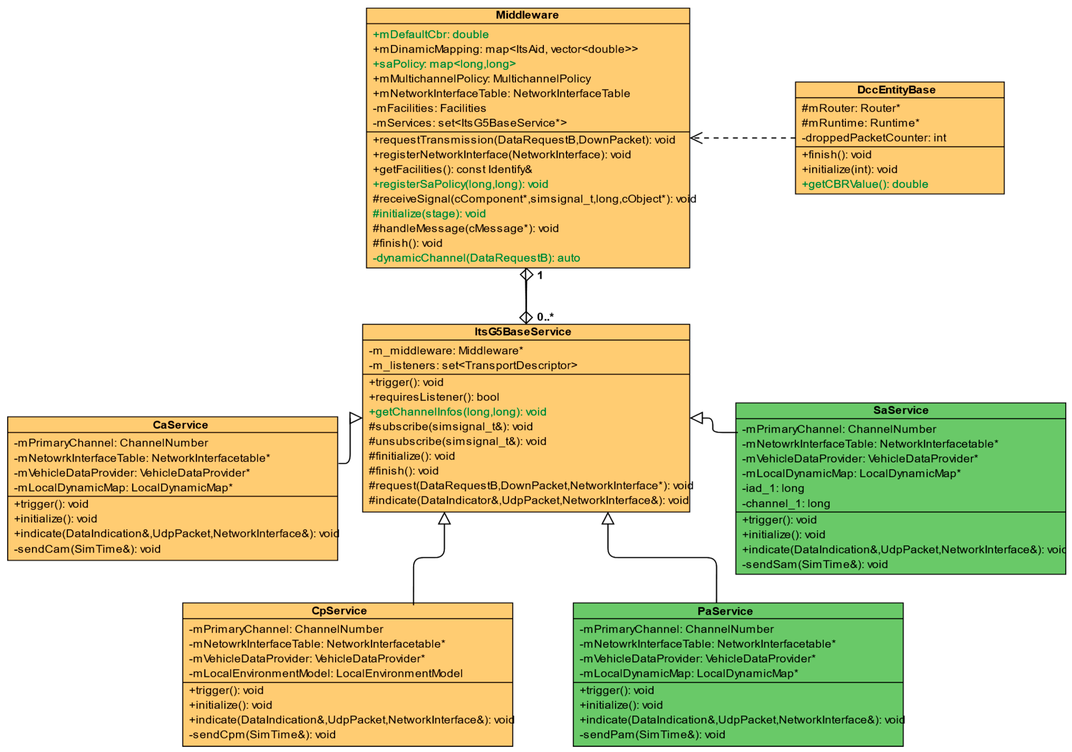
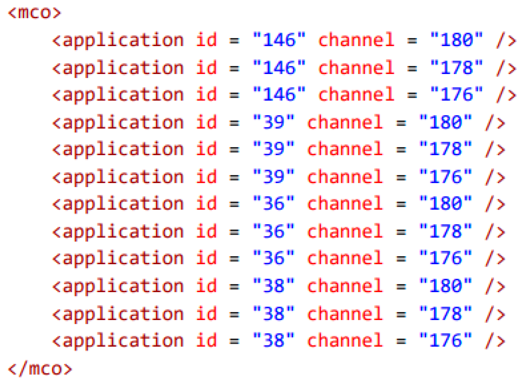
4.1. Static MCO Implementation in Artery

Artery, an extended ITS-G5 model collection for INET/OMNeT++, already has the basic extensions needed to implement MCO [36]. Until this MCO model was deployed in Artery, modelers only checked if the Router class was assigned to the Middleware. If so, the packet was simply sent out on its only interface. A few years ago, modifications were added to allow users to statically select the channels they want to use before the simulation begins. For each scenario, we need to provide an application XML description file (services.xml) containing the type of systems to test and the ports they listen on. With the static MCO feature, a channel field was added where you can define the identifier of the channel that will be used in the simulation. This is how the Middleware component will know which channel to put the listener assigned to that application on. In addition, another XML file is needed (mcoPolicy.xml) where you can tell the Artery’s Middleware which channels you want to use in the simulation and which are the default CCH and the secondary SCH channels. This Middleware is the component that plays a central role in transmitting and receiving ITS-G5 messages in Artery. This is where we initialize the objects in the Facility layer and the applications used during the simulation. When a message is about to be sent out, the requestTransmission function defined here will be executed. In this case, the request function of the Router class assigned to the Middleware will be called inside the function. It will first compose the PDU of the packet, based on the type of the message to be sent and the transport protocol information given in the parameter, provide it with security headers, and then send it out to the lower layers.

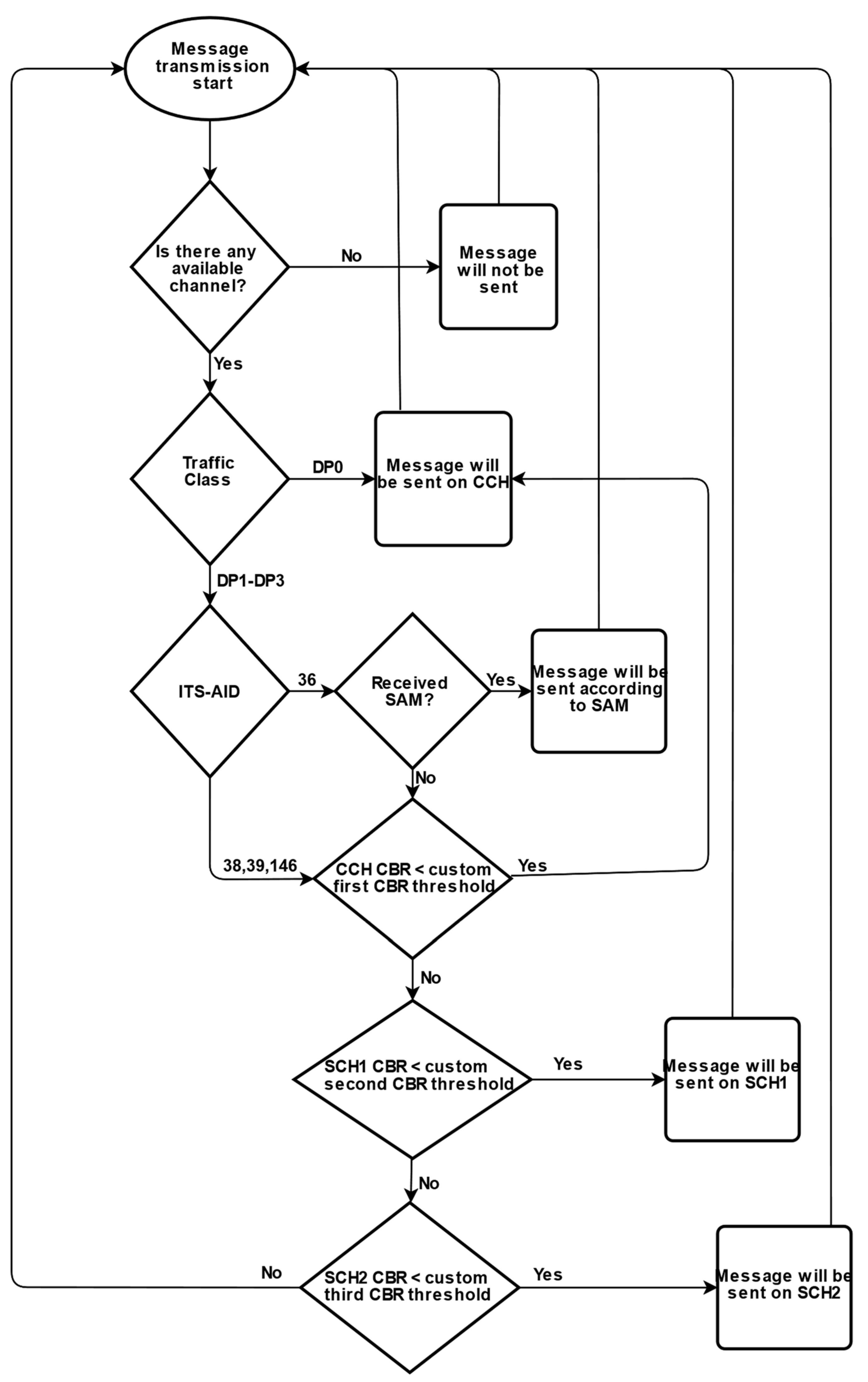
4.2. Our Proposal: A Novel, CBR-Based Dynamic Channel Selection Model

In the Middleware class of Artery, the initialization function was expanded with a new parser method to read the CBR threshold values from the XML file, and the whole channel-selection procedure was implemented here. A new saPolicy data member was added to store the AID-channel pairs obtained from the SAM, and a channel load data member was obtained to store the current CBR. The real-time CBR value is processed in the DccEntityBase class. A simple function was created to obtain the CBR value, which is normally stored in vectors.
SaService and PaService were created to simulate SAM and PAM message types. Both were implemented according to CaService. In SaService, the basic channel information was stored statically. A new function was created to register advertisement information to the corresponding Middleware in the base class of all the service classes. When a SAM message is transmitted, in the indicate function of the SaService, the SAM is parsed, and the advertisement information can be registered to the Middleware. Figure 1 shows the simplified structure of the abovementioned components of Artery. The green parts present newly created modules and functions.
First, the MCO Policy XML file (mcoPolicy.xml) needs to be configured by specifying the Application ID (AID) of the applications we want to use and then the corresponding channel (Figure 2). Multiple channels can be assigned to a single AID, which allows the applications to switch channels at runtime because, from this file, they know they could use another channel as an alternative. After processing the XML file, the ID-channel number pairs are saved in the Middleware.
In order to make the channel-change usage more modular, a Channel Change XML (channelChange.xml) data tag was created in the Middleware NED file. Here, we can provide an XML containing the ITS-AID of the service used in the simulation and the three corresponding CBR thresholds. The first CBR tag belongs to the primary CCH channel, the second to SCH1, and the third value to SCH2. This is processed like other XML files during the Middleware initialization and saved in nDinamicMapping, a newly created map type data member, which stores the specific AID and its related CBR values (Figure 3). Since the map type has approximately 40 bytes of overhead, a double typically requires 8 bytes, a vector has 24 bytes of overhead, and every element (which is a double) within it needs 8 bytes. Moreover, three AIDs with three CBR threshold values require around 288 bytes of memory to store them.
The dynamic channel-switching method was implemented in the Middleware. A new function was created called dynamicChannel, which selects the interface that satisfies the CBR constraints based on the DataRequest parameter and then calls the request function of the associated Router class on this chosen interface to actually send the request. The DataRequest parameter contains the most critical information about the transmission. It includes the destination and source ports and the GeoNet parameters. From the GeoNet data tag, ITS-AID data can be extracted, so the Middleware will know what kind of message it is. The Traffic Class field can also be found there. When dynamicChannel is called, first, the ITS-AID is retrieved in the request parameter. Then, based on the given AID, it can select the channels to which this AID is assigned. After that, it sorts the resulting channels in order of priority. For the channel selection, the Middleware first looks at the DCC profile. This can range from DP0 up to DP3. It puts the DP0 request on the primary channel exclusion, while in some cases, it goes through the channel pool and checks the CBR values. If the current CBR parameter exceeds the threshold assigned to that channel, it continues to the next one. When it finds a channel with a CBR value below the allowed level, it returns the interface assigned to that channel for sending the message. The message will not be sent if there is no channel with a CBR level lower than the required threshold.
Since both CAM and CPM have a DP2 profile, further distinctions are used. If the message profile to be sent is DP2 (DP1-DP3), we also look at the message type. If it is a CAM (AID = 36), then the CBR values for the CAM defined in channelChange.xml will be the thresholds. If it is a CPM (AID = 146), the CBR values will be related to the CPM. Using this method, different CBR values for different message types can be set. If we want a message to stay longer with a higher-priority channel, we need to specify higher CBR threshold values. When the ITS-AID is 36, another distinction is used, namely the Service Announcement Service (SAS). This means that vehicles can get SAMs with channel information regarding which channel will be the next CAM in the queue transmitted. For the sake of simplicity, it was implemented only for CAM. The complete algorithm is depicted in (Figure 4).

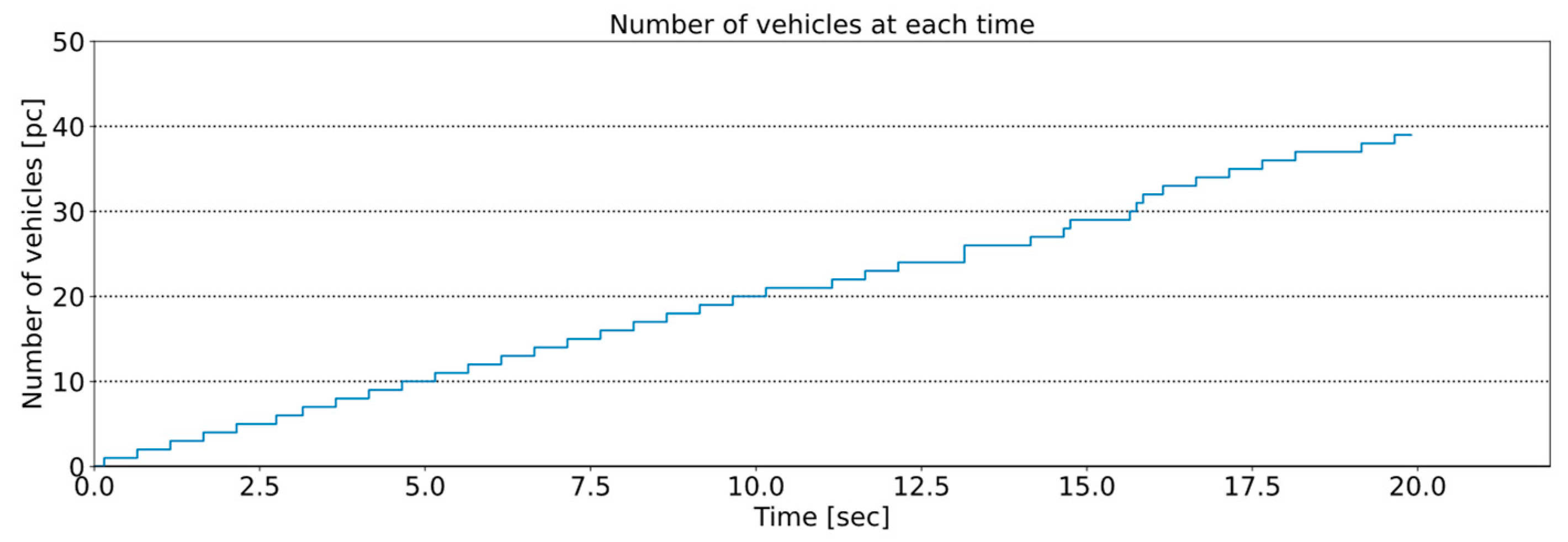
4.3. Implemented Use Cases and Configurations Details

The playground is a 6 × 6 square grid track with 300 m of side length, where one grid is precisely 50 m of side length (Figure 5). The track is, therefore, not large so that vehicles can generate a lot of messages in a relatively limited geographic area and short time. Hence, the saturation rate of the used channel/channels can increase rapidly.
A 500 ms vehicle generation interval was used in the simulations to introduce road users to the grid. This means that, until the end of the simulation time, SUMO will generate about two cars per second and launch them on a randomly chosen route. Thus, SUMO produced 40 vehicles till the end of the considered 20 s simulation scenario (Figure 6).
The testing was divided into three major parts. First, we used one channel. Then, we measured the saturation state of the channels, using static allocation; and, finally, we simulated the dynamic channel allocation method. CAM, CPM, PAM (Precise Awareness Message, applied only for these scenarios based on CAM models), and SAM message types were used by all vehicles during the simulations.

5. Results

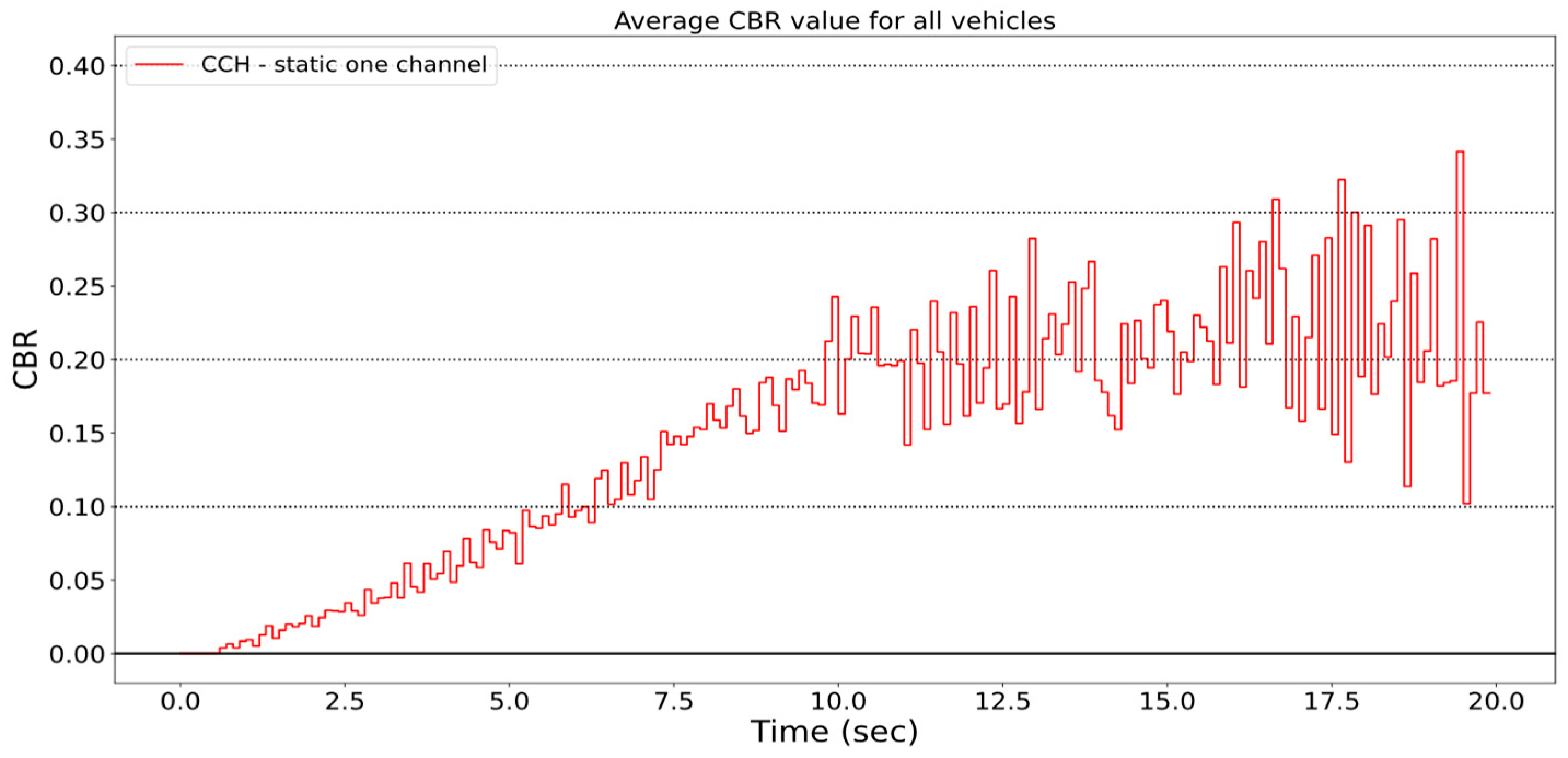
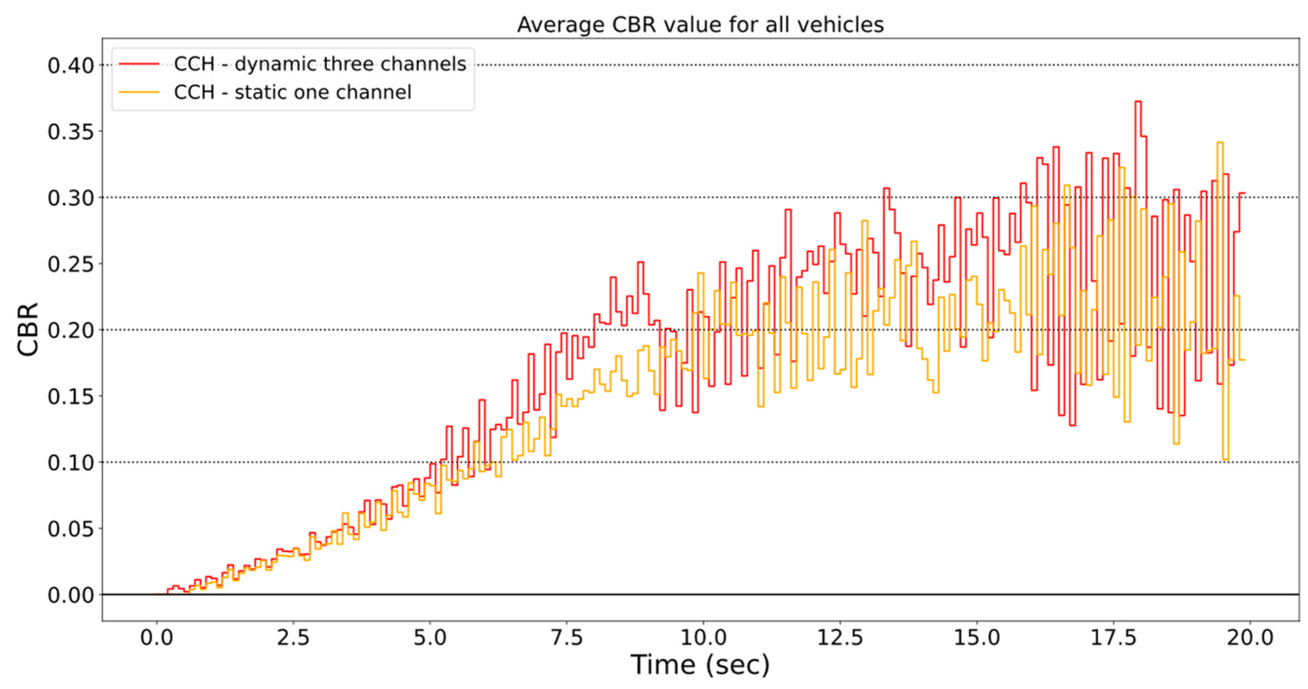
5.1. Statically Configured Single Channel for All V2X Communications

First, messages are sent out on the primary channel. ITS-AID–channel pairs are set statically to the CCH channel in this case.
If all message types are sent on the same channel, the average CBR is around 0.3, but it can climb a little above 0.4 towards the end (Figure 7). Up to about the 10th second, congestion-control mechanisms are activated, and it drops back a bit of packet transmission frequency. That is why the gradient of the function decreases afterward.

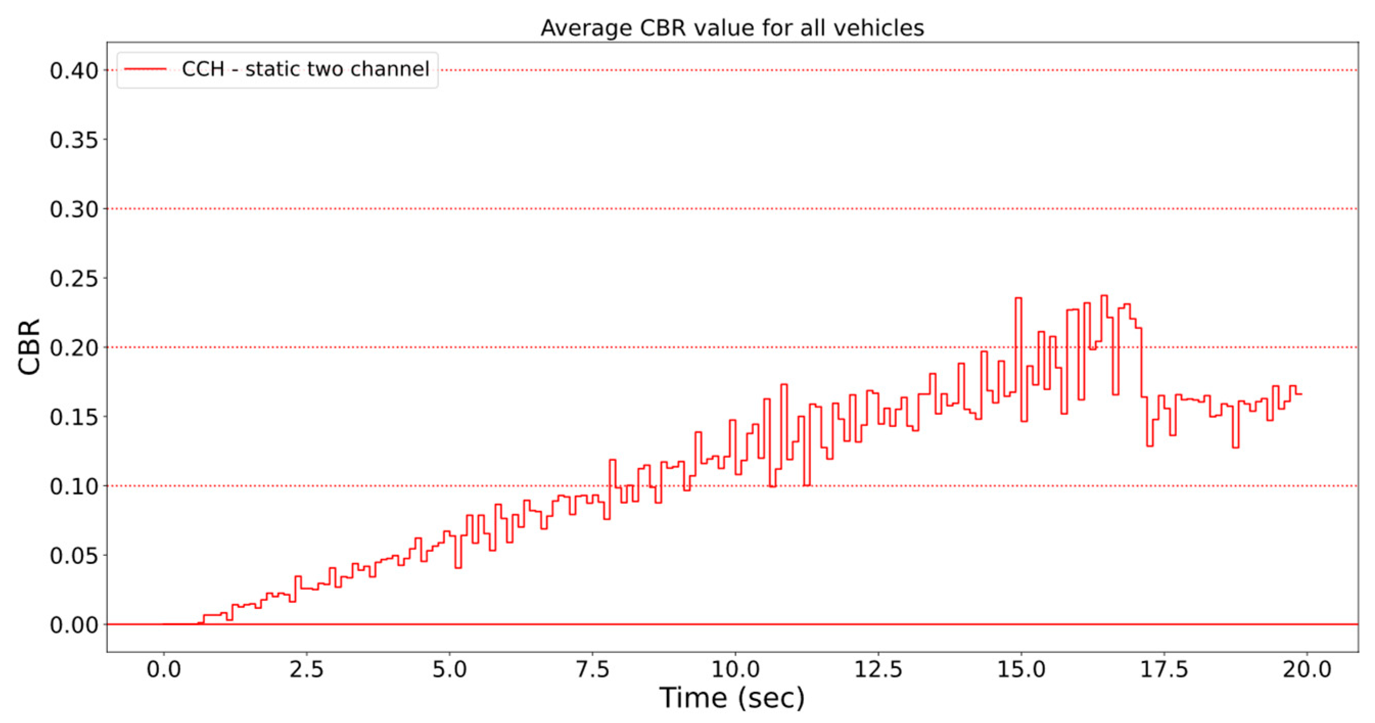
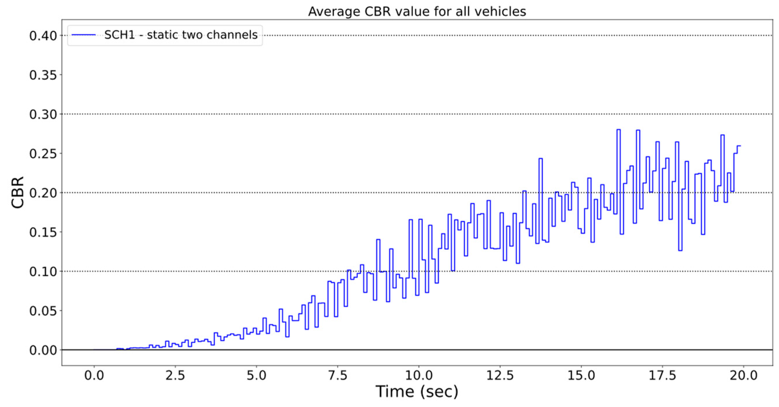
5.2. Statically Configured Two Channels

In this case, only one channel is assigned to a service, and these pairs remain unchanged during the simulation. The multi-channel environment still exists; however, if a channel is oversaturated, only the built-in DCC algorithms will be triggered in order to control the saturation. The middle layer will not transfer the traffic to another channel: applications will transmit based on the initial channel assignment. SAM, PAM, and CAM messages are sent via CCH, while CPM is on the SCH1.
In this situation, the CBR of the CCH channel increases until the 16th second; after that, it decreases slightly due to DCC (Figure 8). The highest value was 0.23 and a little above 0.15 towards the end of the simulation. It is clearly visible that the CBR value is much lower in this case compared to the situation where all application data were transmitted on one channel.
For SCH1, it is a bit different (Figure 9). Here, the CBR increases almost to the end of the simulation. The highest value was around 0.28. However, the CBR is still lower on average than if it were sent out on a single channel.

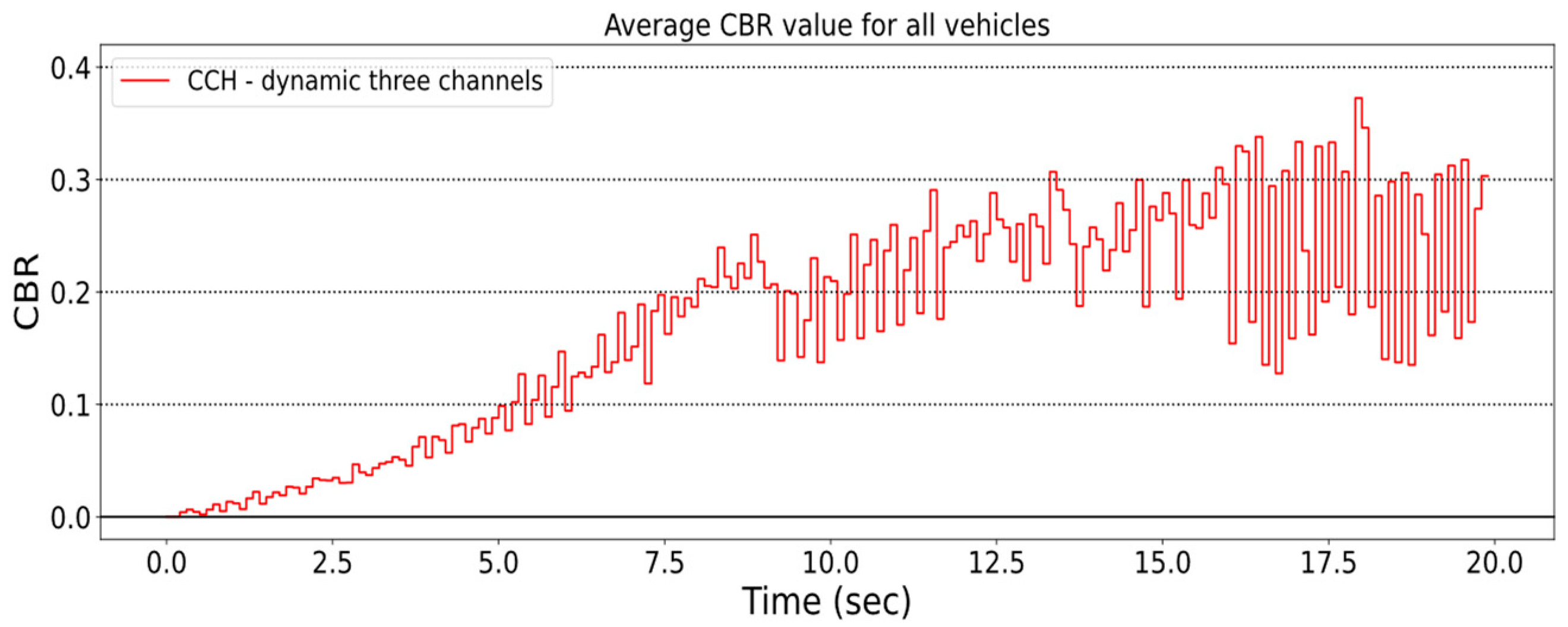
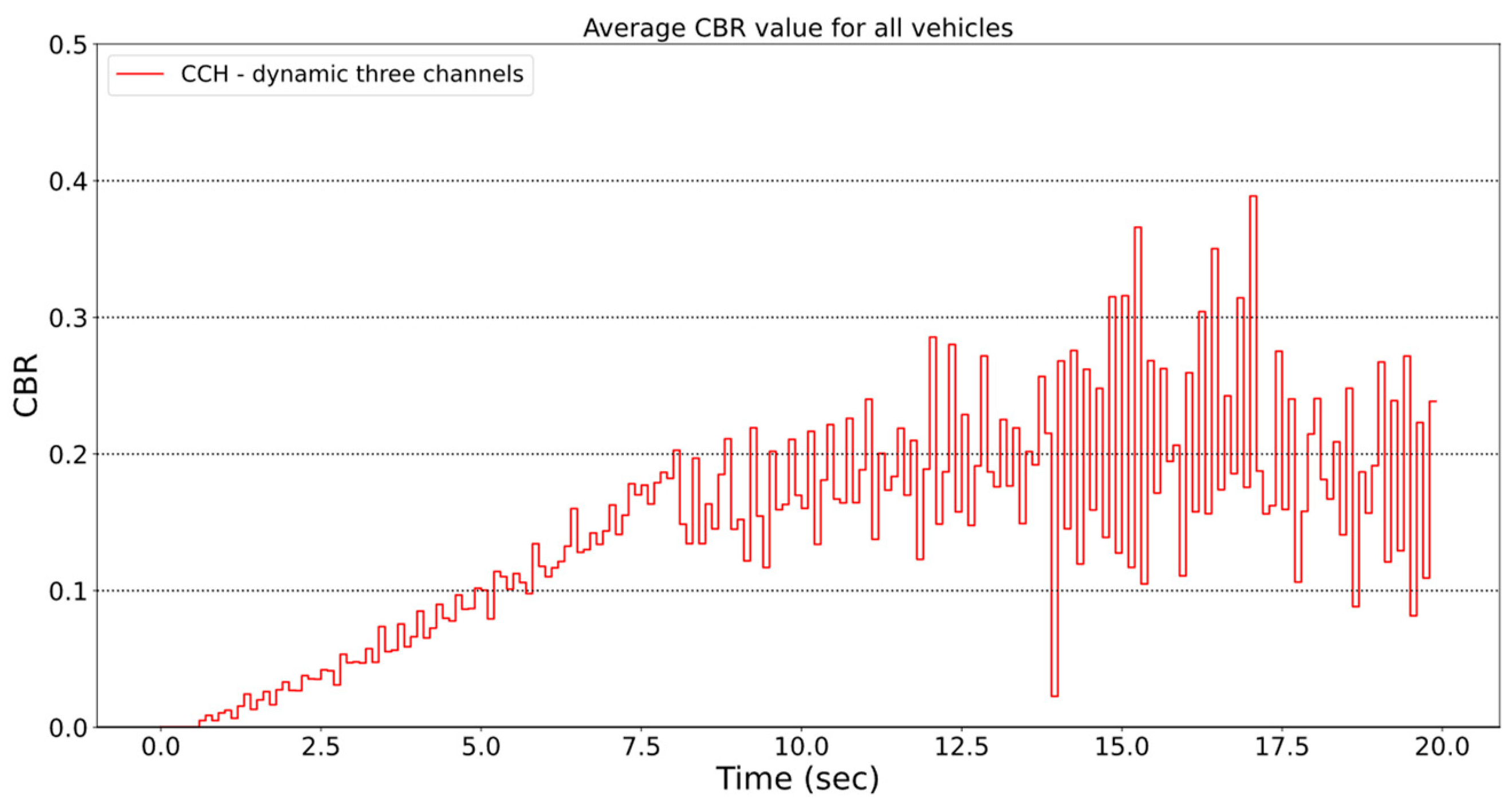
5.3. Using Three Channels of Dynamic V2X Traffic Assignment with Different CBR Thresholds

5.3.1. High CBR Threshold: Every Application Remains on One Single Channel

In this case, one channel situation is reconstructed. This means that the CBR thresholds are set to a high value (i.e., 0.8) in the config files, so it presumably will not be exceeded by the channel’s saturation level during the simulation. This way, we can successfully keep all message types assigned to the primary channel.
The CBR values (Figure 10) are similar to the static single-channel scenario (Figure 7), as Figure 11 depicts, so the mechanism performs as expected. The CBR value here is also around 0.28.
The CBR values for SCH1 and SCH2 are nearly zero (Figure 12 and Figure 13). Thus, indeed, all the traffic was handled by the CCH. Only a minimal signal can be seen, and it is there because the channels are adjacent in frequency, and interference can disturb the CBR values.

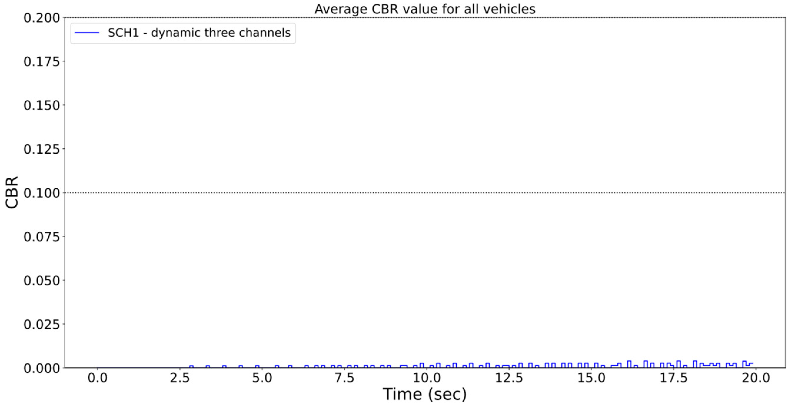
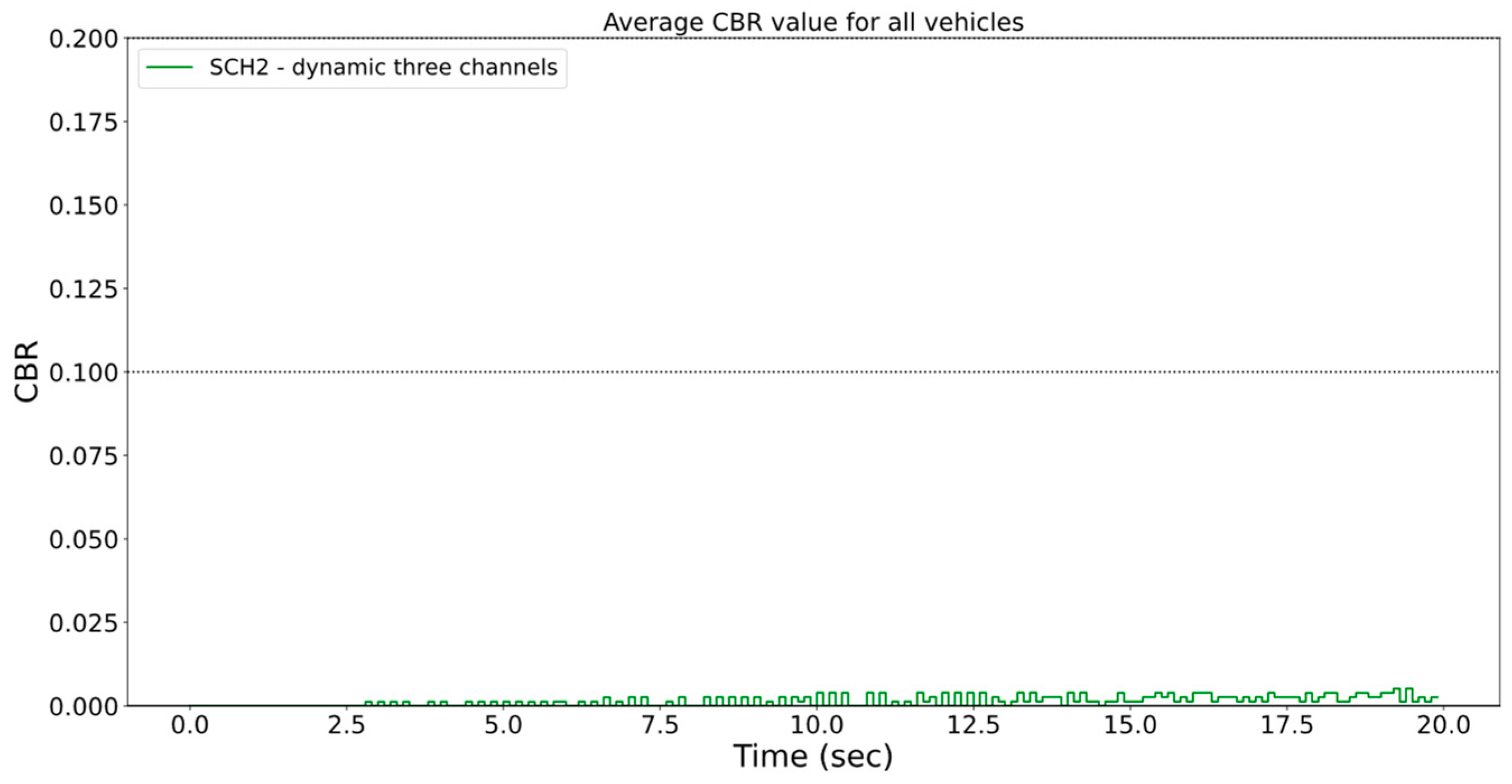
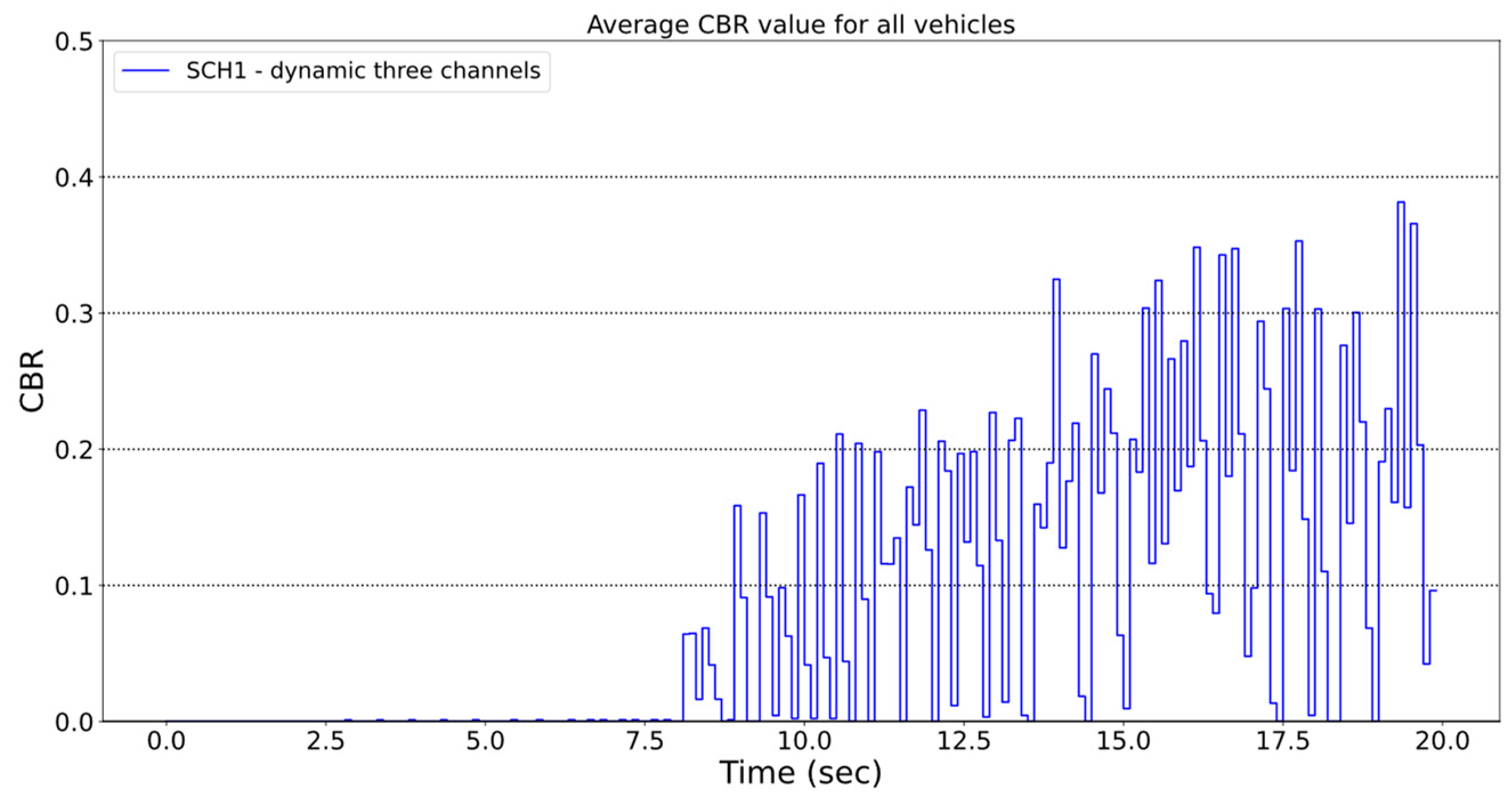
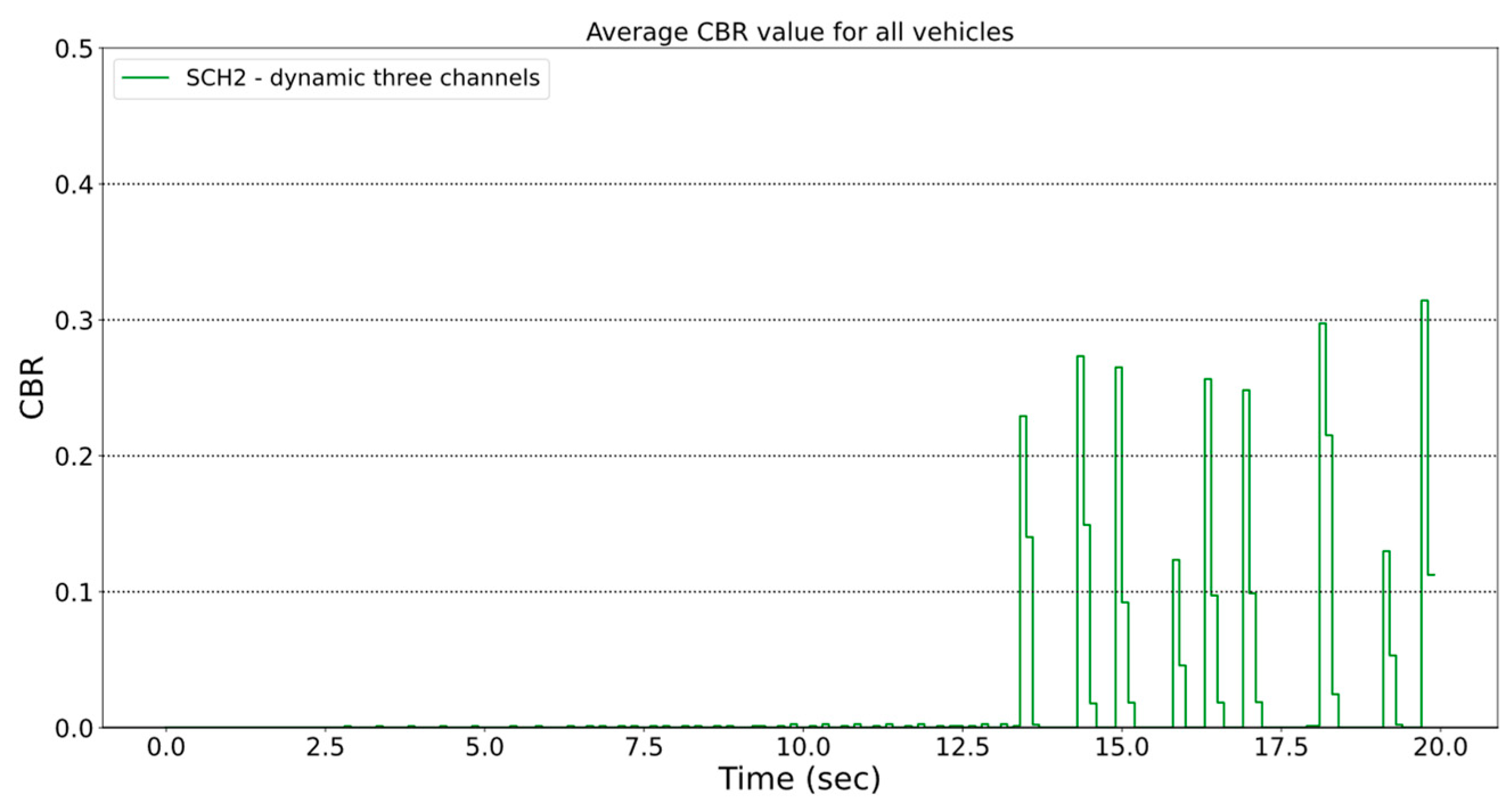
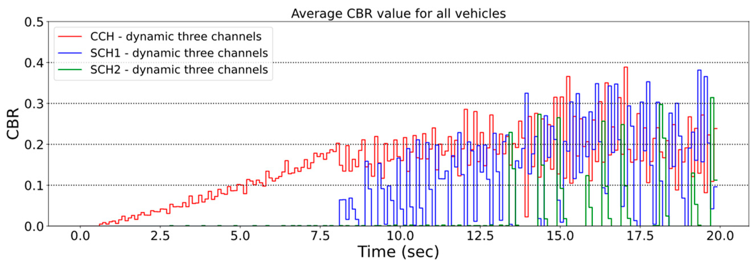
5.3.2. Low Threshold: All Three Available Channels Will Be Used

In this scenario, all three channels are used. The CBR threshold is now set to be equal for all ITS facilities protocols. With this, the Middleware switches between channels relatively simultaneously. This is an excellent way to understand the dynamic shifting behavior. The first CBR level is set to 0.2, the second to 0.2, and the third to 0.5.
Figure 14 shows that the CBR value increases nicely up to 0.2, and then when it reaches its height, the saturation settles in the vicinity and fluctuates near 0.2 until the end of the simulation.
On SCH1, the CBR of the channel is zero for about 7.5 s, so no transmission was sent until that. When the CBR on CCH reaches and exceeds the threshold (Figure 14), the middle layer detects that and immediately switches the next packet in the queue to the next SCH1 channel. From then on, SCH1 will also saturate and then concentrate around 0.2 (Figure 15).
On the SCH2 channel, no CBR was measured until the 13th second. When the SCH1 exceeds its threshold level, the Middleware will transfer the current message to SCH2, so we see that, around the 13th second, the CBR value increases on this channel (Figure 16) Thus, it puts the instant message on SCH2 if the CBR on SCH1 exceeds the threshold and the CCH channel is also above the threshold.
We summarize our experiments with low CBR threshold in the three dynamic channel scenarios (Figure 17). It shows that channel load can be measured only on CCH in the first thirds. After it exceeds its threshold value at 7.5th seconds, the CBR of the second most prioritized SCH1 channel starts to increase. Between 8 and 13 s, the SCH1 and CCH channels keep switching since, when SCH1 exceeds its threshold, the next packet can be transmitted on CCH and vice versa. After 13 s, CCH and SCH1 are both saturated at one moment, so the Middleware puts the given packet onto the SCH2.

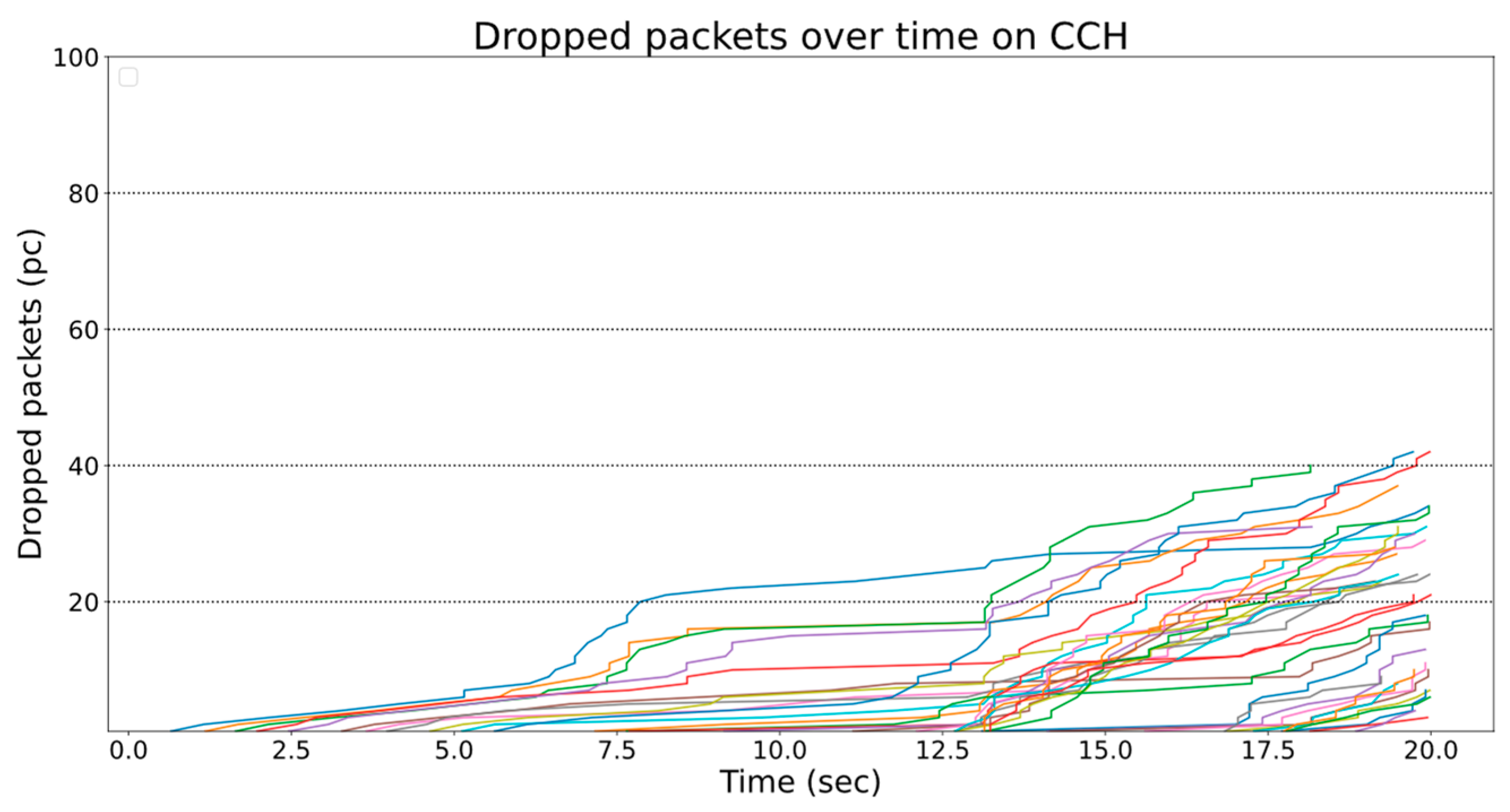
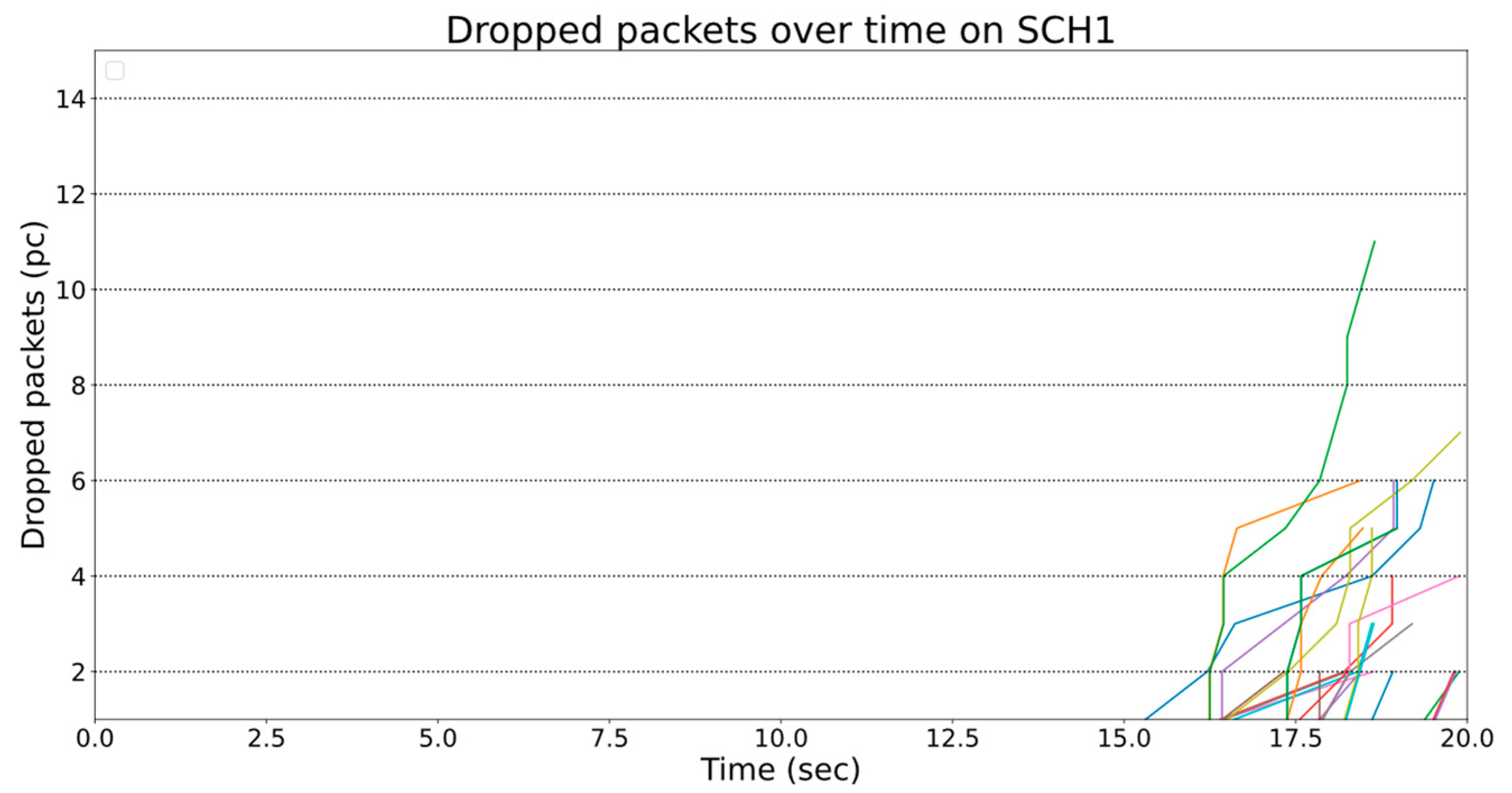
5.4. Dropped Messages over Time

Dropped messages refer to the loss of packets. In this case, it occurs due to the DCC mechanism as the channel becomes more saturated over time. The number of dropped messages was measured in two scenarios to see how the packet loss develops using one static and three dynamic channels.

5.4.1. Statically Configured Single Channel for All V2X Communications

In this scenario, the number of dropped messages constantly grows over time (Figure 18). As the vehicles enter the simulator one after the other, curves start from different locations on the x-axis. For vehicles that have been in since the beginning of the simulation, the number of lost messages is around 175 when our experiment finishes.

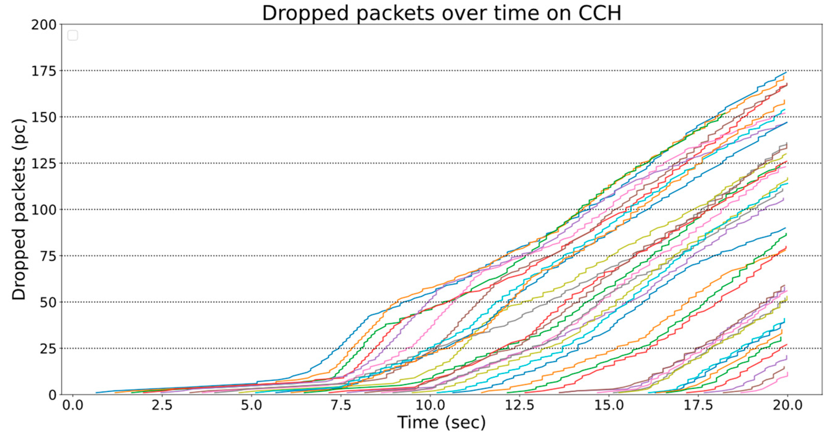
5.4.2. Low Threshold: All Three Available Channels Will Be Used

When the dynamic channel-switching mechanism is used, the number of dropped messages on the CCH is significantly lower (Figure 19). Vehicles that have been on the map since the beginning of the simulation had about 40 such lost packets.
On the SCH1 (Figure 20), packet drops can only be observed after 15 s. This is because, at the beginning of the simulation, messages are transmitted on CCH, and the congestion rate of the SCH1 is only considerable towards the end of the simulation. The number of dropped messages is even lower than CCH.
On SCH2, no packet loss was measured at all. As can be seen, using more than one channel considerably reduces the number of dropped messages. Before the DCC mechanism kicks in, it transfers the messages to another channel.

6. Conclusions

The CBR may be one of the most valuable measures for triggering dynamic channel switching, as it indicates the current medium’s occupancy. In addition to CBR, other parameters that affect communication can also be good inputs for the channel control algorithm, such as the number of vehicles around the ego vehicle. However, they can all ultimately be traced back to the CBR rate.
The results showed that CPM is one of the message types capable of easily saturating channels. It can detect as many as 15–20 objects detected, and its message size is over 1000 bytes. For this reason, in a multi-channel environment, it is essential how we distribute larger message types between channels. The proposed CBR-based dynamic shifting model worked as expected, meaning that no more channels were used as long as the channel saturation was within the threshold. As more and more vehicles were on the road, the saturation increased, and more channels were activated.
Furthermore, the existence of the service advertisement message is crucial, as it can be used to inform other ITS-Ss about the location of other services. The question is whether SAM is worth it to distribute to be able to notify other users at the expense of additional traffic.
As a further development, object/detection prioritization would be handy, as CPM messages are large, and the information must often be sent out in several chunks. In a multi-channel environment, this could be solved by assigning data with different priorities to different channels. This would require advanced mechanisms on the CP service and the Middleware’s dynamic channel assignment decision levels.
Using our proposed dynamic MCO model, complex scenarios can be implemented to evaluate the broadest scale of advanced channel selection algorithm variants, V2X application classification schemes, and methods to optimize ITS-G5 radio resource usage.

Author Contributions

Conceptualization, O.V. and L.B.; methodology, O.V. and L.B.; software, O.V.; validation, O.V.; original draft preparation, O.V. and L.B.; review and editing, O.V. and L.B.; supervision, L.B.; project administration, L.B.; funding acquisition, L.B. All authors have read and agreed to the published version of the manuscript.

Funding

This work was supported by the European Union project RRF-2.3.1-21-2022-00004 within the framework of the Hungarian Artificial Intelligence National Laboratory.

Data Availability Statement

Not applicable.

Acknowledgments

The authors would like to sincerely thank András Wippelhauser for the helpful discussions, valuable comments, and support in Artery/OMNeT++. The authors also would like to thank Peter A. Kara from the Budapest University of Technology and Economics for his help and support.

Conflicts of Interest

The authors declare no conflict of interest.

Abbreviations

AIDApplication ID
CAMCooperative Awareness Message
CBRChannel Busy Ratio
CCHControl Channel
C-ITSCooperative Intelligent Transport Systems and Services
CPMCooperative Perception Message
C-V2XCellular V2X
DCCDecentralized Congestion Control
DENMDecentralized Environmental Notification Message
DPDCC Profile
DSRCDedicated Short-Range Communication
ITSIntelligent Transport System
ITS-G5access technology to be used in frequency bands dedicated for European Intelligent Transport System (ITS)
IVIMInfrastructure to Vehicle Information Message
MCMManeuver Coordination Message
MCOMulti-Channel Operation
NEDNetwork Description
PAMPrecise Awareness Message
PDUProtocol Data Unit
QoSQuality of Service
RSURoadside Unit
SAMService Announcement Message
SCHservice channel
SPservice provider
SPATEMSignal Phase and Timing Extended Message
SRDshort-range device
SUservice user
SUMOSimulation of Urban Mobility
V2XVehicle-to-Everything
VAMVulnerable Road User Awareness Message
WAVEIEEE Wireless Access in Vehicular Environments
WSAWAVE Service Advertisement

References

  1. Araniti, G.; Campolo, C.; Condoluci, M.; Iera, A.; Molinaro, A. LTE for vehicular networking: A survey. IEEE Commun. Mag. 2013, 51, 148–157. [Google Scholar] [CrossRef]
  2. Campolo, C.; Molinaro, A. Multichannel communications in vehicular Ad Hoc networks: A survey. IEEE Commun. Mag. 2013, 51, 158–169. [Google Scholar] [CrossRef]
  3. Chen, S.; Hu, J.; Shi, Y.; Zhao, L.; Li, W. A vision of C-V2X: Technologies, field testing, and challenges with chinese development. IEEE Internet Things J. 2020, 7, 3872–3881. [Google Scholar] [CrossRef] [Green Version]
  4. László, B.; András, C.; András, V.; Károly, F. A V2X-Kommunikáció Alkalmazási Területei. Available online: https://www.hte.hu/documents/4652308/4695917/HT2021-ksz1_3-Bokor-etal.pdf (accessed on 5 April 2023).
  5. Car 2 Car Communication Consortium. Guidance for Day 2 and beyond Roadmap. 2019, C2C-CC Roadmap, C2C-CC White Paper Number 2072, p 42. Available online: https://www.car-2-car.org/fileadmin/documents/General_Documents/C2CCC_WP_2072_RoadmapDay2AndBeyond_V1.2.pdf (accessed on 21 April 2023).
  6. ETSI. Intelligent Transport Systems (ITS); Vehicular Communications; Basic Set of Applications; Part 2: Specification of Cooperative Awareness Basic Service. January 2019. Available online: https://www.etsi.org/deliver/etsi_en/302600_302699/30263702/01.04.01_30/en_30263702v010401v.pdf (accessed on 5 May 2023).
  7. ETSI. Intelligent Transport Systems (ITS); Vehicular Communications; Basic Set of Applications; Part 3: Specifications of Decentralized Environmental Notification Basic Service. April 2019. Available online: https://www.etsi.org/deliver/etsi_en/302600_302699/30263703/01.03.01_60/en_30263703v010301p.pdf (accessed on 5 May 2023).
  8. Lyamin, N.; Vinel, A.; Jonsson, M.; Bellalta, B. Cooperative Awareness in VANETs: On ETSI EN 302 637-2 Performance. IEEE Trans. Veh. Technol. 2018, 67, 17–28. [Google Scholar] [CrossRef]
  9. ETSI. Intelligent Transport Systems (ITS); Vehicular Communications; Basic Set of Applications; Facilities Layer Protocols and Communication Requirements for Infrastructure Services 2020. February 2020. Available online: https://www.etsi.org/deliver/etsi_ts/103300_103399/103301/01.03.01_60/ts_103301v010301p.pdf (accessed on 24 April 2023).
  10. ETSI. Intelligent Transport Systems (ITS); Vehicular Communications; Basic Set of Applications; Analysis of the Collective Perception Service (CPS); Release 2. December 2019. Available online: https://www.etsi.org/deliver/etsi_tr/103500_103599/103562/02.01.01_60/tr_103562v020101p.pdf (accessed on 21 April 2023).
  11. Pereira, G.; d’Orey, P.M.; Aguiar, A. Poster: Cooperative perception platform for intelligent transportation systems. In Proceedings of the 2020 IEEE Vehicular Networking Conference (VNC), New York, NY, USA, 16–18 December 2020; pp. 1–2. [Google Scholar]
  12. ETSI. Intelligent Transport Systems (ITS); Facilities Layer Function; Part 1: Services Announcement (SA) Specification. May 2017. Available online: https://www.etsi.org/deliver/etsi_ts/102800_102899/10289001/01.01.01_60/ts_10289001v010101p.pdf (accessed on 5 May 2023).
  13. Whyte, W.; Petit, J.; Kumar, V.; Moring, J.; Roy, R. Threat and Countermeasures Analysis for WAVE Service Advertisement. In Proceedings of the 2015 IEEE 18th International Conference on Intelligent Transportation Systems, Gran Canaria, Spain, 15–18 September 2015; pp. 1061–1068. [Google Scholar] [CrossRef]
  14. Khan, I.; Hoang, G.M.; Härri, J. Rethinking cooperative awareness for future V2X safety-critical applications. In Proceedings of the 2017 IEEE Vehicular Networking Conference (VNC), Turin, Italy, 27–29 November 2017; pp. 73–76. [Google Scholar] [CrossRef]
  15. Brakemeier, A.; Schmidt, R.K. Multi-channel Usage in Day 2 and beyond EU V2X Systems 22nd ITS World Congress, Bordeaux, France, 5–9 October 2015. Available online: http://leinmueller.de/lib/exe/fetch.php/publications/lsbbs15mco.pdf (accessed on 23 April 2023).
  16. Spaanderman, P. Multi Channel Operaton. 2016. Available online: https://docbox.etsi.org/Workshop/2016/201603_ITS_WORKSHOP/S02_ITS_NEXT_CHALLENGES/MULTI_CHANNEL_OPERATION_spaanderman_paulsconsultancy.pdf (accessed on 5 April 2023).
  17. ETSI TR 103 439; Intelligent Transport Systems (ITS); Multi-Channel Operation Study; Release 2. ETSI: Sophia Antipolis, France, October 2021.
  18. CAR 2 CAR Communication Consortium. Multi-Channel Operation (MCO); Part 1; Functional Requirements. 2020. Available online: https://www.car-2-car.org/fileadmin/documents/General_Documents/C2CCC_WP_2082_MCO-Requirements_V1.1.pdf (accessed on 5 May 2023).
  19. CAR 2 CAR Communication Consortium. Multi-Channel Operation (MCO); Part 2; Technical Capabilities and Limits. 2020. Available online: https://www.car-2-car.org/fileadmin/documents/General_Documents/C2CCC_WP_2084_MCO-TechnicalCapabilies_V1.0.pdf (accessed on 5 May 2023).
  20. Härri, J.; Kenney, J. Multi-channel operations, coexistence and spectrum sharing for vehicular communications. In Vehicular Ad Hoc Networks; Springer: Berlin/Heidelberg, Germany, 2015; pp. 193–218. [Google Scholar]
  21. Leinmüller, T.; Spaanderman, P.; Festag, A. Next steps for Multi-Channel Operation in EU V2X Systems. 23rd ITS World Congress, Melbourne, Australia, 10–14 October 2016. Available online: http://leinmueller.de/lib/exe/fetch.php/publications/lsf16mco.pdf (accessed on 3 May 2023).
  22. Khan, I.; Härri, J. Integration Challenges of Facilities-Layer DCC for Heterogeneous V2X Services. In Proceedings of the 2018 IEEE Intelligent Vehicles Symposium (IV), Changshu, China, 26–30 June 2018; pp. 1131–1136. [Google Scholar] [CrossRef]
  23. Intelligent Transport Systems (ITS); Decentralized Congestion Control Mechanisms for Intelligent Transport Systems Operating in the 5 GHz Range; Access Layer Part. April 2018. Available online: https://www.etsi.org/deliver/etsi_ts/102600_102699/102687/01.02.01_60/ts_102687v010201p.pdf (accessed on 2 June 2023).
  24. Chen, Q.; Jiang, D.; Delgrossi, L. IEEE 1609.4 DSRC multi-channel operations and its implications on vehicle safety communications. In Proceedings of the 2009 IEEE Vehicular Networking Conference (VNC), Tokyo, Japan, 28–30 October 2009; pp. 1–8. [Google Scholar] [CrossRef]
  25. IEEE Std 1609.4-2016; IEEE Standard for Wireless Access in Vehicular Environments (WAVE)-Multi-Channel Operation. Revision of IEEE Std 1609.4-2010. IEEE: New York, NY, USA, 21 March 2016; pp. 1–94. [CrossRef]
  26. Lee, D.; Ahmed, S.H.; Kim, D.; Copeland, J.; Chang, Y. An efficient SCH utilization scheme for IEEE 1609.4 multi-channel environments in VANETs. In Proceedings of the 2016 IEEE International Conference on Communications (ICC), Kuala Lumpur, Malaysia, 22–27 May 2016; pp. 1–6. [Google Scholar] [CrossRef]
  27. Song, C. Performance Analysis of the IEEE 802.11p Multichannel MAC Protocol in Vehicular Ad Hoc Networks. Sensors 2017, 17, 2890. [Google Scholar] [CrossRef] [PubMed] [Green Version]
  28. CAR 2 CAR Communication Consortium Multi-Channel Operation (MCO); Part 3; MCO Concept. October 2022. Available online: https://www.car-2-car.org/fileadmin/documents/General_Documents/C2CCC_WP_2085_MCO-Concept_V1.0.pdf (accessed on 5 May 2023).
  29. Wang, Q.; Leng, S.; Fu, H.; Zhang, Y. An IEEE 802.11p-Based Multichannel MAC Scheme with Channel Coordination for Vehicular Ad Hoc Networks. IEEE Trans. Intell. Transp. Syst. 2012, 13, 449–458. [Google Scholar] [CrossRef]
  30. Justin Gopinath, A.; Nithya, B. An optimal multi-channel coordination scheme for IEEE 802.11p based Vehicular Adhoc Networks (VANETs). In Proceedings of the 2019 11th International Conference on Communication Systems Networks (COMSNETS), Bengaluru, India, 7–11 January 2019; pp. 38–43. [Google Scholar] [CrossRef]
  31. Priandono, R.R. Design and Evaluation of Multi-Channel Operation Implementation of ETSI GeoNetworking Protocol for ITS-G 5. Master’s Thesis, Eindhoven University of Technology, Eindhoven, The Netherlands, August 2015. Available online: https://pure.tue.nl/ws/files/47037031/799532-1.pdf (accessed on 3 April 2023).
  32. Boban, M.; Festag, A. Service-actuated multi-channel operation for vehicular communications. Comput. Commun. 2016, 93, 17–26. [Google Scholar] [CrossRef]
  33. Mak, T.K.; Laberteaux, K.P.; Sengupta, R. A Multi-channel VANET Providing Concurrent Safety and Commercial Services. March 2005. Available online: https://escholarship.org/content/qt9ms1897t/qt9ms1897t_noSplash_07b8b26b50d1dfeca0dda863e25b6dbf.pdf?t=krnjfz (accessed on 16 April 2023).
  34. NS3 Discrete-Event Network Simulator. Available online: https://www.nsnam.org/docs/models/html/wave.html (accessed on 5 May 2023).
  35. ETSI. Intelligent Transport Systems (ITS); Communication Architecture for Multi-Channel Operation (MCO); Release 2. November 2021. Available online: https://www.etsi.org/deliver/etsi_ts/103600_103699/103696/02.01.01_60/ts_103696v020101p.pdf (accessed on 16 April 2023).
  36. Riebl, R. Artery-OMNeT++ V2X Simulation Framework for ETSI ITS-G5. Available online: https://github.com/riebl/artery (accessed on 5 May 2023).
  37. Wippelhauser, A.; Turi-Kováts, S.; Ognjanović, I.; Bokor, L. Modeling and evaluation of Service Announcement in V2X networks. In Proceedings of the 2022 26th International Conference on Information Technology (IT), Vienna, Austria, 19–22 July 2022; pp. 1–4. [Google Scholar] [CrossRef]
Figure 1. Simplified UML class diagram of the related Artery components.
Telecom 04 00019 g001
Figure 2. Extended structure of the mcoPolicy.xml configuration file.
Telecom 04 00019 g002
Figure 3. Tag structure of the novel channelChange.xml configuration file.
Telecom 04 00019 g003
Figure 4. The implemented channel-selection algorithm.
Telecom 04 00019 g004
Figure 5. Simulation map: 6 × 6 grid track for cars.
Telecom 04 00019 g005
Figure 6. Number of vehicles in the simulator for the used 500 ms generation interval.
Telecom 04 00019 g006
Figure 7. CCH CBR values—one channel (SAM, CPM, CAM, and PAM).
Telecom 04 00019 g007
Figure 8. CCH CBR values—two static channels (SAM, PAM, and CAM).
Telecom 04 00019 g008
Figure 9. SCH1 CBR values—two static channels (CPM).
Telecom 04 00019 g009
Figure 10. CCH CBR values—three dynamic channels (SAM, CPM, CAM, and PAM), threshold = 0.8.
Telecom 04 00019 g010
Figure 11. CCH CBR values—three dynamic channels and one static channel comparison, threshold = 0.8.
Telecom 04 00019 g011
Figure 12. SCH1 CBR values—three dynamic channels, threshold = 0.8.
Telecom 04 00019 g012
Figure 13. SCH2 CBR values—three dynamic channels, threshold = 0.8.
Telecom 04 00019 g013
Figure 14. CCH CBR values—three dynamic channels, thresholds = 0.2, 0.2, 0.5.
Telecom 04 00019 g014
Figure 15. SCH1 CBR values—three dynamic channels, thresholds = 0.2, 0.2, and 0.5.
Telecom 04 00019 g015
Figure 16. SCH2 CBR values—three dynamic channels, thresholds = 0.2, 0.2, and 0.5.
Telecom 04 00019 g016
Figure 17. Comparison of CCH, SCH1, and SCH2 CBR values—three dynamic channels, thresholds = 0.2, 0.2, and 0.5.
Telecom 04 00019 g017
Figure 18. Dropped messages of every vehicle on CCH, using a single static channel.
Telecom 04 00019 g018
Figure 19. Dropped messages of every vehicle on CCH using dynamic channel selection.
Telecom 04 00019 g019
Figure 20. Dropped messages of every vehicle on SCH1, using dynamic channel selection.
Telecom 04 00019 g020
Table 1. Summary of selected Day 1–2 facilities protocol messages.
MessageCAMDENMCPMVAMMCM
Transmission typePeriodicEvent-drivenPeriodicPeriodicEvent-driven
ReleaseRelease 1Release 1Release 2Release 2Release 2
Transmission Rate10 Hz–1 Hz10 Hz after trigger effect10 Hz–1 Hz10 Hz–0.2 Hz10 Hz–1 Hz after trigger effect
Hop CountSingle Hop GeoBroadcastMulti-hop GeoBroadcastSingle Hop GeoBroadcastSingle Hop GeoBroadcastSingle Hop GeoBroadcast
DataVehicle’s position, speed, etc.Relevance area, cause descriptionDetected object’s descriptionPedestrian’s and cyclist’s position, speed, etc.Trajectories
Speed, heading
ImportanceBasic status and attribute information Safety-related situations (e.g., hazardous locations) Advertise nearby object’s informationInformation about vulnerable road usersPlanned trajectory to nearby vehicles
Disclaimer/Publisher’s Note: The statements, opinions and data contained in all publications are solely those of the individual author(s) and contributor(s) and not of MDPI and/or the editor(s). MDPI and/or the editor(s) disclaim responsibility for any injury to people or property resulting from any ideas, methods, instructions or products referred to in the content.

