
An Analysis of MPTCP Congestion Control


Department of Engineering Technologies, School of Science, Computing, and Engineering Technologies, Swinburne University of Technology, John Street, Hawthorn 3122, Australia
*
Author to whom correspondence should be addressed.
Telecom 2022, 3(4), 581-609; https://doi.org/10.3390/telecom3040033
Submission received: 24 August 2022
/
Revised: 25 September 2022
/
Accepted: 6 October 2022
/
Published: 19 October 2022
Abstract
:Many devices contain more than one network interface. There is scope for multi-path transfer to utilise these network interfaces simultaneously. Multi-path TCP (MPTCP) is designed to provide improved resilience and resource utilisation through multi-path transfer. One of the key goals of MPTCP is to preserve fair resource sharing with regular TCP at network bottlenecks. Although the coupled congestion control algorithms can achieve this goal by coupling subflow congestion windows, the algorithms always assume that the subflow paths will share a bottleneck. As a consequence, MPTCP is unable to maximise throughput over all available paths at a non-shared bottleneck. We present a survey about MPTCP and its coupled congestion control algorithms. We then show that MPTCP coupled congestion control algorithms perform poorly when paths are disjoint and/or do not have similar delay and/or bandwidth characteristics.
1. Introduction
Where end devices have multiple network interfaces, the use of multiple paths in the Internet is a promising approach to increase network throughput. Internet paths are dynamic and diverse, these paths are very likely to have different characteristics. For example, WiFi and cellular interfaces have different bandwidth and delay capabilities. Additionally, the TCP/IP stack was designed based on a system in which nodes are single-homed. As such, enabling multi-path utilisation in a network can be challenging. The gap between the single-path and multi-path networks has been explored at different TCP/IP layers. Various solutions have been proposed to allow multi-path transfer in some capacity [1,2].
The Multi-path Transport Control Protocol (MPTCP) is an extension of the TCP transport protocol that allows existing TCP-based applications to make use of multiple paths where that option is available. MPTCP can allow simultaneous use of multiple addresses/interfaces between source and destination hosts [3].
An MPTCP host can use multiple IP/port addresses to take alternate paths to a destination host. MPTCP distributes data streams onto different paths using subflows. Each subflow looks and behaves as an independent TCP flow. A subflow can dynamically be added/removed from the MPTCP connection without terminating the connection [3].
MPTCP operates at the transport layer and is transparent to the application and network layers. An MPTCP connection appears like a regular TCP and does not require any modification to network applications. To the network layer, each MPTCP subflow appears as a TCP flow [3].
Similar to TCP, MPTCP is connection-oriented and reliable, and is designed to work with the Internet. MPTCP can provide the following major benefits, (1) higher throughput from multiple bandwidth aggregation; (2) resilience improvement; and (3) better resource utilisation [3].
In TCP, a mechanism is required to coordinate the transfer and to avoid congestion. In this context, Congestion Control (CC) algorithms play an important role in decreasing the loss rate and stabilising the entire network. Each flow should meet certain requirements to ensure that available network resources are fairly shared amongst all users [4,5].
Typically, CC algorithms monitor the incoming feedback signal to adjust the flow sending rate. Packet loss and packet delivery delay are two common signals used in CC algorithms. Both loss-based and delay-based CC use the Congestion Window (cwnd) to indicate each path’s availability/capacity. TCP CC maintains a cwnd for each flow which dynamically adjusts based on network conditions. The window increases when no congestion event has occurred and decreases when congestion is detected. Overall, CC aims to reduce congestion, maintain high link utilisation and provide a fair share of the available resources [5].
MPTCP CC algorithms can be divided into two groups, uncoupled and coupled CC. With uncoupled CC, each subflow deploys a separate/independent cwnd. The subflow cwnd is not affected by loss events on other paths. Existing loss-based and delay-based CC algorithms can be used as an uncoupled CC in MPTCP [1,3].
With coupled CC, a shared cwnd is used across all the subflows in a connection. Currently deployed coupled CC algorithms include Linked Increased Algorithm (LIA) [6], Opportunistic Linked Increase Algorithm (OLIA) [7], Balanced Linked Adaption Congestion Control Algorithm (BALIA) [8] and Weighted Vegas (wVegas) [9]. LIA, OLIA and BALIA are considered loss-based while wVegas is delay-based.
The notion of “fairness” has been an ongoing topic of research in both MPTCP and TCP. MPTCP uses multiple network paths simultaneously in order to improve overall throughput performance. One of the design goals for MPTCP CC mechanisms is to ensure fair coexistence of multi-path and single-path (sub)flows within the same network. The protocol is considered fair if it behaves like a TCP connection under shared path conditions. As such, the resources should be equally shared among all connections (TCP and MPTCP) [1,3].
Uncoupled CC maintains a separate cwnd on each subflow independently. As an example, three subflows sharing the same link occupy three times as much bandwidth as a regular TCP flow. This would not be fair to TCP connections at shared bottlenecks [6].
Coupled CC focuses on the fairness of the overall connection instead of a single subflow. All subflows share a coupled cwnd which shifts traffic between different subflows to ensure the overall throughput is not more than a single TCP flow [6].
In this paper, we present a survey and analysis of MPTCP. In particular, we describe the general principles of MPTCP. We give an overview of a fairness definition from different perspectives and analyse existing MPTCP CC algorithms. In particular, the purpose of the analysis is to investigate the performance of the currently deployed MPTCP coupled CC algorithms under different scenarios. It is important to understand whether current solutions to MPTCP CC function both when the subflows share a bottleneck and when the subflows follow disjoint paths. We would also like to obtain a better understanding of the performance of coupled CC algorithms when the characteristics of the subflow paths differ.
The paper is structured as follows. Section 2 gives an overview of the emergence of multi-homed devices and the MPTCP protocol. In Section 3, we describe what a network path is and the importance of path selection in multi-path networks. Section 4 discusses a number of existing multi-homing solutions at each layer of the Internet protocol suite. The MPTCP protocol is briefly discussed in Section 5. More detailed discussion of MPTCP scheduling follows in Section 6 and Section 7.
Finally, in Section 7, we discuss the currently deployed CC mechanisms for the MPTCP protocol. We contribute to the ongoing MPTCP fairness discussion by providing an overview of fairness from a flow level and network level perspective. In particular, we discuss the definition of the concept of fairness for MPTCP, and use a simulation and experiments to validate and compare the results with expected theoretical CC mechanisms. A conclusion is presented in Section 8.
2. Multi-Path Transport Control Protocol—An Overview
The Internet is made up of billions of connected devices world-wide. Until recently, end-hosts connected to the Internet were typically single-homed. As an example, connected via a single WiFi interface. More recently computing devices such as laptops and mobile phones are more likely to be equipped with several network interfaces, for example WiFi and cellular, while average Internet speeds have gradually increased over the years, the transport protocols used for transferring data between devices have evolved more slowly. The Transmission Control Protocol (TCP) [10] first originated in the 1970s to provide reliable delivery between networks. Today, TCP remains the Internet’s default transport protocol with few extensions [1,2].
Protocols established for single-homed devices are unable to realise the potential network throughput performance that multi-homed devices are theoretically able to achieve. For example, TCP can only use a single path between end-hosts per session, and the connection has to be terminated and re-established when shifting from one interface to another. As such, end-hosts cannot take advantage of redundant paths and additional capacity that exists over multiple links [1,2].
To enable multi-homing at end-hosts, the Internet Engineering Task Force (IETF) designed the TCP extension called Multi-path TCP (MPTCP) [3]. When multiple links are concurrently available, MPTCP transfers traffic utilising all of the available paths (subflows). This increases the potential for higher overall throughput and resiliency. MPTCP is compatible with TCP-based applications and is already deployed on the Internet [3].
Each MPTCP connection needs to coordinate data transmission across its subflows. Current implementations use a scheduler and congestion control (CC) to manage how the end-hosts transfer data over the available paths. The role of the scheduler is to decide which links to utilise (best path) based on path availability and specific criteria (e.g., RTT, congestion window size). Once paths are selected, the MPTCP scheduler distributes the data among the selected links. The scheduler must rely on the CC algorithm to make a decision on the length of data to allocate to the subflows [1,3].
In a single-homed device, it is the task of CC to optimise performance while simultaneously not congesting the path. Traditionally, CC is applied to a single path between two end-hosts. TCP CC dynamically modifies the sending rate of the path to ensure full utilisation while reducing the sending rate in the case of a congestion event. Depending on the CC algorithm, congestion events may have different responses. The CC algorithm modifies the sending rate by setting the congestion window size of a TCP connection. The window defines how much data is allowed onto the path [4].
Multi-path CC operates at either the connection-level or at the individual subflow level. Two CC approaches in MPTCP are uncoupled and coupled CC. When using uncoupled CC, each subflow manages its congestion window independently of the other subflows or overall connection information. With coupled CC, the window of the entire connection is shared between subflows. Each path congestion window is modified after considering the current state of the overall connection [1,3].
3. Path Selection
A packet contains all the information required to reach a destination when it gets sent into a network. Network links used by a packet to move between routers/hops and reach a destination is referred to as a path. In the Internet, multiple paths can exist between a sender and a receiver. A sender must select a path to transfer new data onto [1].
Originally, path selection took place at layer 3 (network layer). Path selection in layer 3 (routing) is made based on network conditions rather than endpoint and application requirements. Such decisions carry the risk of decreasing transport-layer performance. More recently, multi-homed devices have the ability to select the best path. For example, a path can be selected using dynamic scheduling and flow-control techniques [1].
A multi-path scheduler can decide how much data and through which interface to distribute an application data stream [1]. Figure 1 shows a simple scheduler sending data onto two different paths. As can be seen, the application sends data to the output queue. The scheduling mechanism selects the path through which the data gets transmitted.
Having multiple paths can be beneficial depending on the available paths and their condition, whether they are disjoint or share a common bottleneck. End-hosts gather information about paths to help the scheduler make efficient decisions. Each layer might provide different information to the scheduler. For example, a scheduler can integrate with the transport layer and congestion-control algorithm to check available congestion on each path as well as the RTT to select a transmission path [1].
3.1. Path Diversity
Internet paths are unpredictable and change dynamically. Both network and end-hosts play a part in changing a paths characteristics. On a single path, it is possible for packets to arrive out-of-sequence. This problem becomes more complex when multiple paths are used to transfer data as each path can have different characteristics. For example, a flow through a smartphone’s cellular interface often experiences higher RTT as compared to a smart-phone’s Wi-Fi interface [11]. Some common issues include head-of-line blocking and window limitation.
3.1.1. Head-of-Line Blocking
When packets are distributed through different paths, different path delay and loss rates might contribute to out-of-sequence delivery at the receiver. For example, consider two paths between nodes where one node has a lower delay than the other. Packets that are transferred through the lower delay path need to wait at the receiver’s buffer until the high-delay packets arrive.
The delay difference and out-of-order packets at the receiver buffer cause a problem called head-of-line blocking. Head-of-line blocking can lead to a network burst which is not desirable for certain types of traffic. For example, streaming applications since they require a large amount of receive buffer for a good user experience [11].
3.1.2. Window Limitations
When using a transmission layer protocol such as TCP, a sender typically uses the minimum of cwnd and the receiver buffer (rwnd) to transfer data. A problem called window blocking can occur when a large portion of the receive buffer is occupied by out-of-order packets. In such cases, the receive window is filled with out-of-sequence packets and hence the sender shrinks its send window. The problem affects available paths with higher performance (lower delay, higher bandwidth) since no data can be transferred until head-of-line blocking data are positively received and acknowledged [1].
Another issue caused by a full receive buffer is called send buffer blocking. When a sender transmits data, the segments stay in its buffer until the data are acknowledged. This causes the sender to hold on to the out-of-order packets until the blocking packets are received [1].
4. Multi-Homing Solutions
It is becoming more common for end hosts to be connected via multiple interfaces to the Internet. Similarly, ISPs offer multiple paths to allow routers to send traffic with the same destination across different paths. In data centres, a large number of servers often communicate with each other over redundant links [2].
Despite this, the protocols widely deployed today were not originally designed for redundant, multi-path networks. The lack of multi-path aware protocols prevents the potential benefits that multi-homing can provide. Over time, different solutions at each layer have been proposed to fill the current gap with respect to the layers’ use cases.
4.1. Link Layer
At the link layer, link aggregation mechanisms have been introduced to aggregate the capacity of switches’ multiple interfaces [2]. Generally, the interfaces are aggregated under one logical interface and share the same MAC address. This results in the upper layers being unaware of the link aggregation. The virtual interface aims to increase throughput, provide redundancy and distribute traffic load between switches [2].
The Link Aggregation Control Protocol (LACP) [12] is part of the IEEE 802.3ad specification which allows bundling of multiple physical ports into a single virtual interface. The protocol provides automatic configuration and link aggregation as well as the ability to dynamically detect link failure [12].
LACP exchanges LACP packets between LAN ports in active or passive modes. Active mode starts the negotiation while passive mode responds to the packet negotiation. The protocol identifies the capabilities of each port group dynamically and exchanges this information between the LAN ports. The protocol requires synchronisation between the switches. Further, the switch can only aggregate its links to the next-hop. If the bottleneck is not the next hop, the aggregated links do not provide any benefit to the network bottleneck [12,13].
4.2. Network Layer
There are different proposals to enable multi-homing in the network layer. Some of the common methods are summarised in this subsection.
- Site-Wide Multi-homing: This method refers to when one LAN is connected to the Internet via different transit providers (see Figure 2). Hosts in such a network tend to be single-homed while the gateway router is responsible for multi-pathing. The router can shift end-hosts TCP flows between different transit providers without breaking any connection. Site-wide multi-homing provides redundancy, load balancing and allows policy enforcement. However, the scheduler makes decisions based on the current network condition and preferences rather than the hosts needs [1].
- Mobile IPv4 and IPv6 [14]: Mobile IP uses entities called the home agent and foreign agent to create a tunnel to mobile hosts (see Figure 3). Mobile IP allows mobile hosts to change IP addresses without disrupting/changing the connection. As can be seen in Figure 3, when a mobile node connects to a new gateway (the foreign agent), the mobile node registers a care-of address with the home agent. The care-of address is usually assigned to the logical end point of the tunnel between the home and the foreign network (mainly the foreign agent). The care-of address can be reused for different visiting hosts. When a mobile device shifts from one foreign agent to another one, the home agent will forward data to the foreign agent to end the data to the mobile host.However, the topology relies heavily on traffic passing through the foreign agent as well as the home agent at least once. Further, while mobile nodes can change their own IPs, there is no support for resource pooling and hence bandwidth remains unchanged.
- Site Multi-homingby IPv6 Intermediation (Shim6) [15] Shim6 is a pure end-host based solution which allows IPv6 nodes to have multiple addresses. Shim6 improves load balancing and redundancy. However, it does not provide simultaneous use of multiple paths and is restricted to IPv6 networks.
4.3. Transport Layer
At the transport layer, we are able to take end-hosts requirements/metrics into account. Different solutions have been proposed for this layer. This subsection covers the SCTP and MPTCP protocols.
- Stream Control Transmission Protocol (SCTP) [16]: SCTP is an alternative transport protocol that aims to transfer data in a non-strict reliable manner. This means that data can be transferred in an ordered, partially ordered or an un-ordered manner. SCTP can support multiple IPs per connection. Instead of one data stream per connection, SCTP divides the stream into smaller chunks called associations.To address the head-of-blocking issue, SCTP breaks down the data sequence concept in TCP into so-called regions. Regions are basically an association distributed between multiple sequence streams. Data can be transmitted through any path available to the association.SCTP CC is based on TCP CC. In the case of one association, all the paths share the same CC metrics. If an association has multiple endpoints, then CC might be separate on each path. One of the challenges of SCTP is that it uses a different socket API. This means that applications need to be specifically developed to use SCTP [1,2]. SCTP was not initially compatible with NAT and other middle boxes. Hayes and But, [17] developed a NAT module, called SONATA, to support SCTP. However, SCTP has not been widely deployed outside of niche applications [2].
- Multi-path TCP (MPTCP): In 2013, Multi-path TCP protocol (MPTCP) [3] was released as an extension to TCP to allow multi-homed devices to transfer data through multiple paths simultaneously. MPTCP is compatible with existing TCP applications and functions within the current Internet. The main difference between SCTP and MPTCP is that each sub-flow in MPTCP behaves as an individual and independent TCP flow. MPTCP will be discussed in detail in Section 5.
- –
- Path Manager: A path manager decides when to create/remove flows. The decision is made based on application requirements. Some applications might focus on using multiple paths to avoid failover. In this case, the path manager switches to the secondary path when the primary path fails. In other applications, load balancing plays a crucial part in the performance. In this case, the path manager establishes multiple paths to ensure data can be transferred simultaneously.
- –
- Packet Scheduler: A scheduler is an algorithm that selects a path to transmit packets on. The main MPTCP schedulers will be discussed further in Section 6.
- –
- Congestion Control: The congestion window of each subflow and the overall connection are taken into account based on different properties (e.g., fairness, friendliness, responsiveness). Different MPTCP CC algorithms will be discussed further in Section 7.
5. Multi-Path TCP
MPTCP can improve throughput by allowing devices to aggregate the bandwidth of their available network interfaces when transferring data. For instance, some large data centres use a dual-homed topology to transfer massive flows between servers and end-points. This helps data centres to increase speed when migrating virtual machines, large images/videos backup and replicating content [20,21,22].
Multiple routes can also provide mobility for users. Each end-host can handover traffic from one network interface to another without disrupting the connection. For instance, Apple users (e.g., iPhone or iPads) are able to shift from local Wi-Fi to 4G or vice versa when downloading an important file without losing connectivity [1,22].
MPTCP can also improve network resilience by using available redundant paths in the connection. For instance, when an ongoing session fails, the end-host can use alternative routes while waiting to re-connect on the original path [23]. Similarly, MPTCP path diversity allows users to utilise less congested paths in the case of severe congestion in the primary path [24].
MPTCP in the Networking Stack
With regards to the protocol stack, all MPTCP operations occur at the transport layer. MPTCP interaction with the application layer is identical to TCP. The application layer communicates with MPTCP through a TCP stream socket which is connection-oriented, reliable and bi-directional. MPTCP divides the data received from the application layer into multiple subflows. At the network layer, each MPTCP subflow appears as a regular TCP flow bound to a local IP address [3] (see Figure 4).
6. MPTCP Schedulers
Where multiple paths exist between end-hosts, it is the responsibility of the sender to decide which path to use when transferring data. After establishing the connection, the MPTCP scheduler segments the data in the sender buffer and selects the best available subflow for each packet. A subflow is considered available when the three-way handshake is completed. The scheduler policy is used to select the best path from all currently available subflows [18].
Random selection of a path for data transfer can lead to poor performance, such as head-of-line blocking (Section 3.1.1), window limitations (Section 3.1.2) and bufferbloat. As such, the path selection policy can have a critical impact on ultimate MPTCP throughput. Bufferbloat refers to having excessively large buffers in bottleneck routers. When paths are congested, large buffers result in packets residing in the queue for a long time and causes undesirable latency. Bufferbloat increases network delay and reduces throughput [2].
Since MPTCP became available in the Linux kernel in 2013, several multi-path schedulers have been proposed for different purposes. Each scheduler can be selected based on system and application requirements. Table 1 summarises some of the standard and non-standard schedulers along with their approach in making scheduling decisions.
The default MPTCP scheduler in Linux is minRTT [25]. minRTT first sends data on the subflow with the lowest RTT until its cwnd is full. Then, it starts sending data on the subflow with the next highest RTT. The aim of the scheduler is to optimise throughput and load balancing. minRTT benefits bulk transfer applications and heterogeneous networks. Unfortunately, minRTT can introduce new issues in terms of performance, such as blinder decision and biased-feeding phenomenon [18].
The blinder decision problem is caused by minRTT choosing the path solely based on the path latency, regardless of the other metrics (e.g., transmission rate, packet loss). For example, multiple subflows would choose a path with characteristics of 2 ms delay and 10 Mbps capacity in preference to a path with 3 ms delay and 100 Mbps capacity. Even though subflows travel through the low delay path, there is a risk of packet loss as all the subflows choose the same path which has a lower bandwidth [18].
Biased-feeding is due to the scheduler preferring the same path as long as it is available. The other subflow is only selected when the first subflow is no longer available, most likely due to a full cwnd or loss event. As soon as the first path becomes available, it is immediately selected in preference to other paths [18].
The redundant scheduler sends the same packet over multiple subflows, the packet is lkely to arrive first on the path with minimum latency. When the same packet arrives on other subflows, it is discarded. The redundant scheduler is useful when the application needs to achieve the lowest latency whilst sacrificing bandwidth. It also provides some level of resiliency [25].
The round-robin scheduler simply cycles over subflow queues. The RR scheduler is useful for testing/academic purposes. However, it tends to induce head-of-line blocking and as such often results in drastically reduced performance [25].
Non-standard MPTCP schedulers discussed in the literature focus on improving a single or various metrics to distribute data. Weighted round-robin [26] is an extension to the round-robin scheduler providing optimal load-balancing using subflow weights. Each subflow can be weighted differently Weighted method allows setting values unequally. As such, WRR distributes data based on the specified weight values.
The Shortest Transfer Time First (STTF) [27] scheduler predicts the transfer time on different paths. It then assigns unsent segments to the path with shortest transfer time. STTF can be used in interactive applications which require low transmission time. The Highest Send Rate (HSR) [28] scheduler chooses a subflow based on the highest sending rate.
The Forward Delay Aware Scheduler (DAPS) [29] uses the paths’ RTTs information to improve the probability of in-order packet arrival at the receiver. DAPS main goal is to reduce buffer blocking at the receiver. DAPS uses the Lowest Common Multiple (LCM) of forward delays on all subflows. For example, if the forward delay on the slower subflow is 3 times that of the faster subflow, DAPS would transfer packets 1 to 3 on the faster subflow and packet 4 on the slower subflow.
Lowest-latency with retransmission and penalisation scheduler (LL/RP) [11] is a minRTT extension that retransmits head-of-line packets while penalising subflows that cause head-of-line blocking. Lowest-latency with bufferbloat mitigation (LL/BM) [30] is another minRTT extension that identifies subflows suffering from bufferbloat, and then bounds their cwnd. LL/RP and LL/BM can be used by applications to address the aforementioned issues.
Earliest Completion First (ECF) [31] assigns packets to faster subflows and might not use slower subflows at all. ECF can maximise the use of the fast subflows which is useful for video streaming applications. Similarly, Out-of- Order Transmission for in order arrival (OTIAS) [30] is used in real-time applications as it focuses on utilising the fastest subflow.
As MPTCP is designed to operate over the Internet, it is expected that the protocol should provide good performance across a range of diverse paths where characteristics can change over time. Congestion control and packet scheduling are two important components which greatly impact the performance of MPTCP [1,2]. The existing literature mainly focuses on individual performance evaluation of schedulers or CC algorithms. However, the relationship between CC and the scheduler is vital.
As discussed, the default scheduler of MPTCP (minRTT), prefers the subflow with the smallest RTT as long as their is capacity in the send window to transmit further packets. Detection of when the window capacity is exhausted is performed by the CC algorithms. MPTCP CC adjusts the send rate and balances the degree of congestion within each sub-flow to improve throughput/resource utilisation. Path scheduling is used to distribute data to different subflows to improve transmission efficiency [1]. As the default scheduler is most likely to be deployed on the Internet, we will limit discussion to the interaction and performance of CC algorithms when used with minRTT.
7. MPTCP Congestion Control
It terms of congestion control, using multiple subflows for one connection can be complex. With regular TCP, congestion occurs on a single path between two end-hosts. MPTCP uses different paths to transfer data. Generally, two paths tend to experience different levels of congestion and delay [2,19]. For instance, nearly all smartphones are equipped with at least WLAN and 4G/5G interfaces which each experience different RTTs.
A simple solution is to use a separate congestion control algorithm on each subflow (uncoupled CC). Alternatively, new CC algorithms have been designed in which the total congestion window is shared between all subflows (coupled CC). Figure 5 shows different examples of a single-path TCP and multi-path CC algorithms.
Whether coupled or uncoupled, MPTCP CC algorithms should aim to achieve three main goals [6]:
- Improve Throughput: Total throughput of subflows should be at least as good as a regular TCP flow on the best available path.
- Do No Harm: Subflows should not use more capacity on a shared bottleneck than if they were using a regular TCP flow over any of the paths.
- Balance Congestion: Subflows should aim to avoid congested paths while achieving the first two goals.
The first two goals together ensure fairness at the shared bottleneck. Goal three is based on the concept of resource pooling. When each subflow sends more data through the least congested path, the traffic in the network will move away from congested areas [1,6,32,33].
To achieve fairness (goals one and two), a CC algorithm needs to detect when there is a shared bottleneck or when the paths are separate. In case of a shared bottleneck, the algorithm needs to estimate what a single TCP would get over the same path and split the link’s capacity to that of a regular TCP flow. Similarly, when paths are disjoint, an algorithm needs to ensure subflows achieve higher throughput than TCP.
7.1. Uncoupled CC
With uncoupled CC, each MPTCP subflow behaves as an independent TCP flow, with its own instance of a CC algorithm running independently. For each subflow, cwnd and transmission rate are controlled separately to maximise the use of the path. Uncoupled algorithms are the simplest form of MPTCP CC. Reno [34], NewReno [35], CUBIC [36], and Vegas [37] are among the CC algorithms that can be deployed as uncoupled CC within MPTCP. For example, CUBIC is the current default algorithm for TCP in Linux distributions which is highly scalable and stable when the network bandwidth-delay product is large. Using uncoupled CC makes performance and operation predictable. The uncoupled algorithms are effective at increasing overall MPTCP throughput and are highly responsive to path changes [1,6,32].
However, if N subflows in an MPTCP connection are competing against a single-path TCP flow at a shared bottleneck, the compound MPTCP throughput will be approximately N times higher than that of a single TCP flow. Therefore, uncoupled CC cannot achieve Goal 2 [6]. For example, if an MPTCP with 3 subflows transmits through the same bottleneck as a regular TCP, the MPTCP connection will acquire approximately 75 percent of the bottleneck’s capacity, effectively starving regular TCP.
If each MPTCP subflow uses its own instance of a TCP CC, a TCP flow competes fairly over a shared link with a single MPTCP subflow. Let us consider a simple case of a TCP connection and a single MPTCP subflow sharing a link with transmission rate R. Assuming that the two flows have the same MSS and RTT and that no other TCP/UDP/MPTCP connections traverse the shared link, they should achieve similar cwnd and throughput.
The amount of link bandwidth jointly consumed by the two flows is less than R. As such, no loss will occur and both flows will increase their window by one MSS per RTT as a result of the CA algorithm. When the link bandwidth jointly consumed by the two flows exceeds R, packet loss will occur. The flows will then decrease their windows by a factor of two. Because the joint bandwidth use is less than R again, the two flows will resume increasing their cwnd and therefore throughput. Eventually, loss will again occur and the two connections again decrease their cwnd. This process keeps going on and the bandwidth realised by the two flows eventually fluctuates along the equal bandwidth share line.
7.2. Coupled CC
Coupled CC is a common approach to solve the TCP-friendliness issue of uncoupled CC. MPTCP coordinates cwnd changes across subflows to avoid sending traffic through congested bottlenecks. In the case of shared bottlenecks, MPTCP adjusts the cwnd at different rates to ensure fairness to cross-traffic protocols.
While detecting common bottlenecks can be challenging, the more important decision is how much bandwidth should an MPTCP connection get, even if no bottleneck exists [6]. The major proposed coupled CC algorithms are Linked Increased Algorithm (LIA) [6], Opportunistic Linked Increase Algorithm (OLIA) [7], Balanced Linked Adaption Congestion Control Algorithm (BALIA) [8] and Weighted Vegas (wVegas) [9].
7.2.1. LIA
LIA was the first proposed coupled CC algorithm for MPTCP. In LIA, Slow Start (SS), fast retransmit and fast recovery algorithms are unchanged from TCP-Reno. During Congestion Avoidance (CA), the increase component of the Additive Increase Multiplicative Decrease (AIMD) algorithm is coupled among subflows. Upon arrival of an ACK on each subflow, cwnd is increased as a proportion of the total cwnd. The LIA algorithm increases cwnd for subflow i as per (1) on receipt of an ACK, where is defined as per (2). Parameters and are the size on each subflow and the sum of total of all subflows, respectively. Parameter refers to RTT on subflow i. Here, we assume that cwnd is maintained in packets.
LIA aims to ensure that an MPTCP subflow is no more aggressive than a regular TCP flow in the same scenario (Goal 2). The increase Formula (1) returns the minimum of the calculated increase for the MPTCP subflow (first argument) and the increase a TCP flow would get in the same circumstances (second argument).
Parameter in (2) describes the aggressiveness of MPTCP. The parameter is calculated in a way that the overall bandwidth of MPTCP is equal to the bandwidth a TCP flow would get on the best available path. To estimate the bandwidth of a regular TCP flow, MPTCP uses estimated loss rates and RTTs, and a computed target rate.
When packet loss occurs on a subflow, cwnd is decreased as per (3). This formula is unchanged from TCP-Reno.
7.2.2. OLIA
Like LIA, OLIA [7] shares the increased state of CA algorithm among subflows and does not modify TCP-Reno behaviour in the case of a loss. OLIA uses the TCP SS algorithm with a slight modification. If there are multiple paths established, the SS threshold is set to one MSS. When there is a single path, the threshold is the same as for TCP. The modification is to prevent sending traffic over congested paths when multiple paths are available.
The OLIA increase algorithm is calculated in the following way. Here, L is the set of subflows with largest cwnd, B is the set of subflows which have the highest throughput (best path) but do not have largest , and N is the number of subflows. We assume that cwnd is maintained in packets.
The increase algorithm in (4) uses two terms. The first term adapts a TCP compatible version of Kelly and Voice’s [38] increase algorithm to provide resource pooling, fairness and congestion balancing. The second part provides responsiveness and non-flappiness by using the parameter .
Parameter is defined as per Formula (5). If any best path with small cwnd exists, then is positive for any best path with small windows and negative for the paths with maximum cwnd. OLIA re-forwards traffic from fully used paths to paths with available capacity. If all the best paths have the largest cwnd then is set to zero. The reason being that the available capacity on the best paths is already in use.
7.2.3. BALIA
Peng et al. [8] argue that there is an inevitable tradeoff among friendliness, responsiveness and window oscillation. As such, it is not possible to maximise the performance of all three metrics simultaneously.
BALIA CC was proposed by Peng et al. [8] to generalise existing algorithms and achieve a balanced performance in terms of friendliness and responsiveness. BALIA modifies both increase and decrease phases (AIMD) of the CA algorithm. The minimum SS threshold is set to one MSS when multiple paths are available.
The BALIA algorithm is based only on the subflow paths cwnd and RTT. The increment cwnd for subflow i as per (6) on arrival of an ACK.
Parameter is defined in Formula (8). When BALIA uses a single path, is set to 1, in which both increment and decrement algorithms become the same as for standard TCP.
7.2.4. wVegas
LIA, OLIA and BALIA all use packet loss as a signal to indicate congestion. This means that traffic can shift away from congested paths after a loss event occurs. wVegas is a delay-based coupled CC for MPTCP based on TCP-Vegas [9].
The algorithm is applied to the SS and CA phases of CC. When a path queueing delay is larger than a user-defined threshold, cwnd is reduced and the queue begins to drain. cwnd on other paths get an opportunity to increase based on their estimated capacity. This makes wVegas more responsive to network changes when compared to other coupled CC. Like all delay-based algorithms, wVegas will compete poorly against other loss-based CC algorithms [9].
7.3. Fairness Perspectives
There are different perspectives on “fairness” in the Internet. We define MPTCP fairness from the two perspectives of flow level fairness and network level fairness. Coupling the CC of subflows makes it possible to achieve the fairness when competing with TCP at the flow level. The existing algorithms assume that all paths share the same bottleneck and deliberately ensure that the window does not grow faster than TCP would across all paths. The obvious inference is that it is possible that each separate path could be slightly less aggressive in increasing cwnd. This has the potential to result in reduced throughput when competing with TCP NewReno. The ultimate result is that if an algorithm assumes that all paths share a bottleneck, coupled CC may be limited in its ability to achieve network level fairness.
We expect this issue to be reasonably common. For instance, phone/tablet/IoT devices are generally connected via both LAN/Wi-Fi and/or LoRa/4G/5G interfaces. As such, a multi-homed user typically has access to multiple paths by paying different network providers. Similarly, a wireless network provider might permit users to use multiple Access Points (APs) using MPTCP.
An MPTCP user should expect to obtain the same bandwidth from each AP/network provider as a regular TCP flow. Otherwise, additional payment and privilege are lost. Consider a scenario where an MPTCP connection uses two separate links to transfer data, with one link being shared with a single TCP connection and the second link having no other traffic. Both subflows should be able to fairly compete for bandwidth on their own link regardless of the other link conditions. In this way, the first subflow should gain approximately same amount of bandwidth as the TCP connection while the second subflow attains all of the available bandwidth.
To reach network level fairness, when paths are separated, each MPTCP subflow should perform similar to a single TCP connection. The shared path should not affect other MPTCP subflows ability to obtain bandwidth over their own paths. Otherwise, the MPTCP application will unfairly attain less bandwidth from one path due to conditions on an alternate-unshared-path.
7.4. Analysing How Coupled CC Algorithms Perform
LIA assumes that all subflows contain a shared bottleneck and therefore only increase the cwnd across all subflows as quickly as for a single TCP flow. We would expect that in a situation where the subflows are disjoint, that any situation causing one subflow to grow more slowly (e.g., congestion, reduced bandwidth, increased RTT) would cause collateral damage to the faster path. In this case, the performance of one subflow can cause the other subflow cwnd to grow more slowly which would limit its ability to compete against a single TCP flow.
In OLIA, (4) a subflow is “chosen” as preferred (based on current performance) and resources will be shifted heavily towards one subflow. This has the potential to limit the possibility for MPTCP to ever achieve all the available bandwidth on the alternate subflow. As such, OLIA is not ideal in an environment where loss is not due to congestion but instead is random. In this case OLIA will work to push traffic to the less lossy path. Shifting traffic to the best path can lead to poor performance in the case where all paths are congested. Further, when the best path is congested, OLIA might not be able to at least achieve the throughput of the TCP flow on the best path.
BALIA increments the window by a factor of to improve the performance of the low rate path. However, it still uses a coupled cwnd which limits the higher rate subflow when one path fails to meet the constraints. As such, the throughput achieved by a subflow still depends upon the throughputs of all the other subflows.
Consider a scenario where two subflows follow disjoint paths. In this case, in LIA, we would expect the cwnd on each path to grow at approximately half the rate of TCP New Reno, given that the overall growth will be capped to a single TCP flow. In OLIA, the parameter is set to zero (both paths have similar capacity and hence are considered best path—see Equation (5)). As such, the total window would increase by which is the same as in LIA. In BALIA, we expect a slightly higher growth rate on each path due to the multiplication of .
In the case of a shared bottleneck, this is the expected behaviour, however if the paths are disjoint, then each subflow will be at a disadvantage when competing against other - independent - flows sharing that path. In this case, we would expect MPTCP to underperform and not attain its fair share of the bandwidth.
In order to further investigate these potential disadvantages, we wrote a simple event-based simulation to observe the influence of CC algorithms on cwnd growth. For TCP, the simulation code implemented the TCP NewReno CC algorithm (). To simulate MPTCP connections, the LIA, OLIA and BALIA algorithms were implemented as described in Equations (1), (4) and (6). A simple FIFO queue with a length of 80 packets was modelled to create loss events for the CC algorithms to respond to.
Two scenarios were simulated, one where an MPTCP connection with two subflows were executed over a disjoint path. The second scenario involved an MPTCP connection with two subflows and a TCP connection with single flow. One of the MPTCP subflows (subflow 1) and the TCP flow share a bottleneck link to the destination while the second MPTCP subflow traverses a second, independant link. The simulator initialises all flows with an initial window of 10 Assuming that both links are identical (share the same RTT) and that no other traffic goes through any of the links, each connection/flow starts with the initial window of 10 () and can simulate situations where the RTTs on the two paths are integer multiples of each other. All simulations are run over 600 cycles. The simulator outputs the cwnd values for all (sub-)flows over time for the duration of the simulation.
We first examine the behaviour of the algorithms with regards to cwnd when not competing against any other flows For the case when both paths experience the same RTT, the cwnd for a single TCP flow is plotted against the cwnd for all MPTCP subflows in Figure 6. As is evident from the graphs, we can see that the growth of cwnd for all MPTCP flows is much less aggressive. Given the paths are disjoint, this would imply that MPTCP would be unlikely to achieve it’s share of bandwidth when competing with TCP over the first path.
We next modify the path RTT to understand CC behaviour when the path characteristics differ, all the other simulation conditions stay the same. We consider window growth when the first link is twice as fast as the second link as well as when the first link is three times faster than the second link.
When looking at cwnd growth for different RTTs (Figure 7 and Figure 8), we can see that LIA favours the faster subflow but is still much less aggressive than TCP NewReno. Algorithm performance appears to decrease as the difference in RTT increases (subflow 2 ). The subflow with larger RTT is more heavily impacted and this results in the faster subflow being slightly less aggressive.
For OLIA, with the second subflow having larger RTT, the algorithm increased aggressiveness on the faster path but massively decreased on the slower path. As the RTT difference changes (subflow 2 ), the difference between the faster and slower subflows also increases. BALIA tried to equalise the path loads, resulting in the faster subflow being slightly less aggressive. As the difference in path RTT increases, the differential between the faster and slower subflows also increases.
The simulation results show that MPTCP subflows are less aggresive for all CC algorithms. Given the paths are disjoint, this would result in poor performance on the faster, congested path as well as poor performance on the slower, uncongested path. This outcome will not satisfy the fairness goals with MPTCP attaining less throughput than expected. Even if the faster path is aggressive enough to properly compete with TCP (for flow fairness), the other subflow path remains unused and full throughput will not be achieved (network fairness).
The second scenario was then simulated where the MPTCP subflows continued to traverse disjoint paths, but in this case the first subflow was competing against a single TCP New Reno flow. The results for the case where the RTT for both paths are equal are plotted in Figure 9, Figure 10 and Figure 11.
LIA and OLIA started by using both paths (with the second subflow being much slower). However, the first subflow window quickly drops to zero while the second subflow window grows to use the available resources. The outcome is that despite being on a disjoint path where it is not competing with TCP, the MPTCP flow does not acquire any bandwidth on the first path which it should equally share with TCP. BALIA tries to use the first path’s capacity. However, it is much less aggressive as compared with TCP. The outcome is that BALIA is somewhat more able to attain a fair share but will still accede throughput to the TCP flow.
We now revisit this scenario but consider the situation where the RTT on the second path is twice the first path (). In this case, after one , the cwnd on the first path would grow but be limited in growth since no acknowledgements have been received on the second path. As such, the first subflow grows much less aggressively than TCP NewReno. The second subflow in all the algorithms were for half of the total cycles then started to move the majority of the traffic to the shared subflow (see Figure 12, Figure 13 and Figure 14).
When the second path becomes much slower (), the shared path grows very slowly while the second path window grows faster than the previous simulations. However, the second path is still much less aggressive (see Figure 15, Figure 16 and Figure 17).
Delay-based CC algorithms are mostly used in a controlled environment where all hosts use the same algorithm, such as data centres. For such algorithms, compatibility with other widely used algorithms is not a priority. Loss-based CC is most common and actively used in TCP due to its simplicity [39]. As a result, we did not simulate the wVegas algorithm.
CUBIC is the current default TCP algorithm in Linux and outperforms NewReno in high bandwidth and long distance networks [40]. Given the current equation output, we would expect MPTCP subflows would perform even worse when competing with CUBIC CC.
In this context, it should be noted that the estimation of the available capacity of the paths and their combination is simpler in this simulation than in the Internet where issues such as packet loss, queues and delay exist. The congestion window is the allowable amount of data to be transmitted in an RTT, which varies with the interval of ACKs. When subflows with different conditions share the same congestion window, they experience events that increase or decrease the window size with different intervals. Correlating different RTTs and loss events is difficult since not all flows sharing a link would necessarily experience loss during the same congestion episode.
Coupling the cwnd can potentially address the fairness issue (flow level) where MPTCP and TCP connections share the same bottleneck. However, the throughput achieved by a subflow depends on the throughput of all the other subflows. This affects the fairness of CC to MPTCP itself (network level), especially when packets are sent via diverse paths. Coupling the cwnd could negatively impact protocol resource utilisation. The balance between how to allocate data to the disjoint subflows is difficult to achieve. Favouring a flow with higher bandwidth or reduced RTT could result in underutilised bandwidth if the chosen path is competing with other flows and the alternate - slower - path has no competition. Alternatively, favouring the slower path could result in low aggresiveness on the competitive path, leading to a reduced share of bandwidth.
Ideally, MPTCP needs to understand when paths are disjoint to apply uncoupled CC in these cases, and utilise coupled CC only where paths share a bottleneck.
7.5. Experimental Validation of Simulation Results
In Section 7.4, an analysis and subsequent simulation provided some evidence that MPTCP coupled CC would not work well when subflow paths are disjoint, or when subflow path characteristics are not similar. To validate this idea, we run an experiment based on the topology in Figure 18. This topology mirrors the second scenario from the previous simulations. A single MPTCP connection with two subflows is competing against a single TCP flow. The network is configured such that the two MPTCP subflows take disjoint paths with the first subflow competing against TCP. All experiments are run for ten minutes duration, with the first and last 30 s of data discarded to ensure that throughput measurements reflect performance during steady state conditions.
Experiments are run for bandwidth limitations of 12 Mbps and 24 Mbps. In each case, the set of path RTTs are {(10 ms, 10 ms), (10 ms, 20 ms), (10 ms, 30 ms), (50 ms, 50 ms), (50 ms, 100 ms), (50 ms, 150 ms)}. This repeats the simulation scenarios where the RTT of the second path is equal to, twice, and triple the RTT of first path. All three MPTCP protocols (LIA, OLIA and BALIA) are tested.
As the paths are disjoint, MPTCP should attain all the available bandwidth over the second path. Over the first path, MPTCP should attain half the available bandwidth, with the TCP flow attaining the other half. For the case of 12 Mbps, the first MPTCP subflow and the TCP flow should attain approximately 6 Mbps each, with the second MPTCP attaining approximately 12 Mbps. For the case of 24 Mbps, the ideal scenario should see these numbers doubled to 12 Mbps and 24 Mbps, respectively.
Figure 19 displays the box plot of throughput achieved for each of TCP, MPTCP subflow 1 and MPTCP subflow 2 for a bandwidth of 12 Mbps and RTT of (50 ms, 150 ms). As can be seen, for all three coupled CC algorithms, MPTCP completely backed off on the path shared with TCP (RTT = 50 ms), instead utilising all of the available bandwidth on the second path. This reflects the assumption by all three algorithms that the bottleneck is shared, and that MPTCP should get no more bandwidth than TCP. Had the paths truly been shared, then this is a reasonable outcome, however in the case of the disjoint paths, MPTCP is not attaining a fair bandwidth share for the circumstances, while the coupled CC algorithms behaved more aggressively where the RTTs were lower, the range of throughput attained throughout the experiments were more variable.
We calculate the percentage of expected bandwidth achieved by dividing the average attained throughput by the expected throughput. For ideal fairness, each (sub)flow should score close to 100%. Results for all 18 experiments where the bandwidth is 12 Mbps are listed in Table 2, Table 3 records the results where the bandwidth is 24 Mbps. In all cases, MPTCP was successful in utilising all the available resources on the second path.
LIA performs reasonably well when the path has a low bandwidth delay product (both RTT and bandwidth is low). In this case MPTCP is almost able to fairly compete on the first path and is able to attain more than two thirds of the bandwidth required for fair sharing. BALIA is next best in attaining a reasonable proportion of the expected throughput. In these cases, CC performance is not heavily degraded as the second path RTT increases. This is primarily due to the queueing delay being larger than the path RTT, resulting in the actual difference in path characteristics being less pronounced than those configured. This is further evidenced with results for larger RTT (50 ms, 100 ms, 150 ms) and for larger bandwidth configurations, where the queueing delay has less of an impact on the path RTT.
In all cases, the lack of aggression in growing cwnd of the coupled CC algorithm results in the first subflow not being able to acquire its fair share of the available bandwidth. This is particularly pronounced for large BDP and/or large RTT differences. In these cases, the current coupled CC algorithms can result in the first subflow giving up almost all of its fair share of bandwidth on the shared path.
Confirming the simulation results, the experiments show that MPTCP coupled CC is unable to attain its share of bandwidth in disjoint path scenarios, particularly when path characteristics are not similar. We next examine whether the problem of diverse path characteristics is also problematic in shared bottleneck scenarios, a situation that the coupled CC algorithms were particularly designed to address.
The experiments are repeated using the topology in Figure 20. All settings are the same as for the previous set of experiments with regards to bandwidth and RTT configurations, the only difference is that the two MPTCP subflows are now sharing a bottleneck with the TCP flow. For this scenario, we would expect the TCP flow to attain half of the available bandwidth, and the MPTCP subflows to share the remaining half of the available bandwidth.
Figure 21 displays the box plot of throughput achieved for each of TCP, MPTCP subflow 1 and MPTCP subflow 2 for a bandwidth of 24 Mbps and RTT of (50 ms, 100 ms). In all cases we can see that the coupled CC algorithms preferred the path with lower RTT, with minimal throughput attained on the larger RTT path. Despite this, the combined throughput of both MPTCP subflows was still lower than that attained by TCP for all three algorithms. In this case, loss events on the path with higher RTT are impacting on the ability for cwnd growth on the path with lower RTT and therefore the opportunity for MPTCP to attain a fair bandwidth share. This plot is similar for all throughput plots where the RTT difference is high.
Results for all experimental configurations are recorded in Table 4 and Table 5. When both bandwidth and RTT are low, MPTCP coupled CC is too aggressive and outperforms TCP, in some cases by a large margin. Despite being restricted through using a couple cwnd, MPTCP is able to grow its window more aggressively than TCP and attain a higher share of the bandwidth. When looking at higher bandwidth configurations in combination with lower RTT values, the coupled CC algorithms do a reasonable job in attaining good bandwidth sharing with the TCP flow. However, as the BDP increases, all of the MPTCP coupled CC algorithms start deteriorating in performance, even when path characteristics are the same. Compounding this is that as the path RTT difference increases, the coupled CC algorithms are unable to keep up with the aggressiveness of TCP and give up a significant proportion of their bandwidth to the TCP flow.
The results indicate that MPTCP coupled CC algorithms are only able to attain fair bandwidth sharing under certain network configurations. A change in bandwidth or RTT can lead to either a loss in throughput to MPTCP or high levels of aggressiveness in utilising the available bandwidth. This demonstrates that even when operating in the environment which matches the assumptions made by all MPTCP coupled CC algorithms (i.e., all bottlenecks are shared), that the CC algorithms accede too much bandwidth to TCP and therefore do not perform as designed.
7.6. Alternative Approaches
As discussed, standard coupled CC algorithms were designed to use loss-based or delay-based techniques to detect congestion over paths and ensure TCP-friendliness, while coupling the subflow windows can potentially provide TCP-friendliness at shared bottlenecks, it might affect maximisation of throughput over disjoint paths. In theory, to achieve both goals, MPTCP needs to determine subflows that do not share a point of congestion and subflows that do. Detecting the existence of a bottleneck shared between different protocols, using end-to-end measurements, can be categorised as either using active or passive techniques. Generally, in active detection techniques, the sender probes paths to gather information. With passive techniques, existing data obtained through normal protocol behaviour ( such as ACK packets) is used instead [41].
In this paper, we focus on some of the existing passive methods for the following reasons. First, probing the network with traffic can cause unnecessary congestion and impact the overall protocol performance. Second, inter-packet timing in the transport protocol depends on the CC and flow control mechanisms and any attempt to control/modify flow’s timing can lead to a negative impact on the connection’s performance [41].
Hassayoun et al. [41] developed a passive detection method called Dynamic Window Coupling (DWC). In DWC, both loss and delay signals are used to detect shared bottlenecks. In the algorithm, subflows that share a common bottleneck are grouped in the same set. A centralised entity, called the Subflow Manager (SM), is used to manage the sets. Each set has its own independent cwnd which is increased/decreased by the SM while operating in the CA phase. Flows that do not share any bottleneck with other MPTCP flows of the same connection behave as a regular TCP (NewReno CC).
The process of forming a set starts with a loss congestion event, following this, delay or loss congestion events are examined to group the subflows into the set. When a subflow experiences a packet loss, the SM alerts all the other subflows of the congestion event. The subflow is then removed from its original set and a new active set is initiated. The other subflows are inspected for any congestion indicator in the near past or future of the congestion event. Any subflow that detects a packet loss or a large delay increase is removed from its current set and gets added to the active set. Subflows without any congestion signal remain in their original set. There can be no more than one active set at any instance in time.
DWC showed better aggregated throughput than that for LIA over disjoint paths. The algorithm occasionally failed to detect real shared bottleneck situations. For example, packet loss may occur randomly over lossy networks. Alternatively, congestion events may get synchronised and lead to false positive shared bottleneck detection as the paths experience similar RTT or background traffic. Further experiments by Singh et al. [42] showed that although DWC throughput is higher than that with LIA at distinct bottlenecks, it is often unable to achieve fair bandwidth allocation when sharing a bottleneck with TCP due to its erroneous bottleneck detection.
Ferlin and Hayes [43] designed a shared bottleneck detection (SBD) algorithm named MPTCP-SBD. Where a shared bottleneck is detected, MPTCP subflows use OLIA CC and in disjoint paths, the subflows use decoupled (Reno). The MPTCP-SBD algorithm uses three key statistics of One Way Delay (OWD) to detect bottleneck.
The MPTCP Time Stamp (TS) is modified with microsecond precision. This new TS is included in the data segment by the sender. At the receiver, the relative OWD is calculated by subtracting the arriving TS from the host’s version of current time. The kernel stores the statistics for the last N intervals. Every 350 ms, the SBD decision mechanism uses OWD statistics collected over the last N intervals to group the flows. Flows are grouped into non-congested flows and shared bottleneck flows. The mechanism repeats the process for 10 sets to ensure groupings are accurate. The grouping information is identified using a group ID and is carried in the return ACK via the MPTCP option. The sender uses the SBD feedback to decouple subflows that are in distinct bottlenecks during CA phase.
The SDB algorithm showed improvement in MPTCP throughput over disjoint bottlenecks when compared to OLIA. However, the algorithm was also shown to be slightly more aggressive than OLIA towards TCP flows over shared bottlenecks due to not grouping the same connection subflows, resulting in them acting as independent TCP flows. Furthermore, the background noise on disjoint paths led to a decrease in bottleneck detection accuracy.
Instead of using delay and loss, Wei et al. [44] designed a Shared Bottleneck based CC (SB-CC) scheme based on Explicit Congestion Notification (ECN). The packets that exceed the queue threshold at an intermediate router are marked and the receiver notifies the sender of the ECN in a return ACK. Subflows with marked ACKs in the same time span indicate a shared bottleneck and are grouped in a same set (coupled cwnd). The algorithm uses similar concept to that in DCTCP and uses the subflow congestion degree to dynamically adjust and smooth any fluctuations in window size. The authors experimental results showed that SB-CC, DWC, SBD, BALIA and OLIA achieved fair throughput over a shared bottleneck. As for disjoint paths, SB-CC, DWC and SBD aggregated throughput was much higher than BALIA and OLIA. Specifically, SB-CC and SBD throughput ratio to TCP was close to one. Deployment of such a scheme requires both the end-hosts and intermediary devices to properly react to ECN notifications.
Further, Barik et al. [45] argue that the existing coupled CC are grouped in CA state while most TCP sessions in the Internet are short flows and are unlikely to leave the SS state. MPTCP subflows in SS are uncoupled which results in the compound overall MPTCP cwnd being larger than that of a TCP flow. The authors proposed a new CC called Linked Slow-start Algorithm (LISA) which is applied to the subflows if and only if they are in SS. In LISA, the minimum initial window is set to 3 packets to ensure TCP-friendliness and a maximum of 10 packets to allow full bandwidth achievement in disjoint paths.
When a new subflow joins the connection, LISA finds the subflow with the largest sending rate within the last RTT period, and depending on the subflow cwnd size, [3,10] packets are taken away by the new subflow. LISA also hinders the existing subflow cwnd from increasing for every ACK.
However, LISA could not provide any gains for small file transfers (smaller than 200 KB) and added more weight to the CA phase and reduced overall performance for large file sizes (larger than 500 KB) at shared bottlenecks. Yu et al. showed that the MPTCP CC algorithms do not affect the overall performance of mice flows in high-speed paths. Mice flows operate in SS phase for the entire transmission and they tend to only last for a fraction of a second [46].
The discussed works have not been deployed in the real-network (e.g., Internet). The current simulation/experimental results showed that using a bottleneck detection system at the transport layer could bring some advantages to the current MPTCP coupled CC in some cases. However, none of the proposed solutions fully address the conservative behaviour of coupled CC in various conditions (e.g., different RTTs and bandwidth).
8. Conclusions
Recent developments in Internet applications have increased the need for higher network bandwidth. In an environment where multi-homed hosts are becoming more common, the limitations of TCP in being able to only use a single path to transmit data are becoming more apparent. Where multiple paths exist between end-hosts on the Internet, these paths can be used to provide robustness, higher throughput and load-balancing benefits to applications.
MPTCP was designed to take advantage of these benefits to provide increased throughput, balancing congestion and improving resiliency in the event of failure. MPTCP performs these functions through both scheduling and congestion control algorithms. It’s compatibility with TCP means that MPTCP can be more easily deployed on the Internet where middle-boxes can often interfere with flows that are not TCP or UDP.
However, MPTCP needs to co-exist with existing TCP traffic on the Internet. Current MPTCP congestion control implementations can be divided into uncoupled CC and coupled CC. With uncoupled CC, the CC algorithm on each subflow is independent of the performance of other subflows. This allows each subflow to achieve maximum throughput and behave as an independent TCP connection. However, this leads to unfairness in bandwidth allocation when multiple subflows compete with a TCP connection over the same shared link. As each subflow is independent, each subflow achieves similar throughput to a single TCP flow, leading to MPTCP achieving a multiple of the throughput a TCP flow can attain. An MPTCP connection with N subflows (hence N cwnd) will approximately grow the overall connection window N times faster than a single TCP flow over a shared bottleneck. As such, when the path is shared, using uncoupled CC cannot provide fairness towards TCP flows.
With coupled CC, a shared congestion window is used across all the subflows in a connection. As such, the overall throughput of an MPTCP connection cannot be higher than that of a single TCP on the best end-to-end path. As MPTCP is designed to operate over the Internet. It is expected that MPTCP CC should provide good performance across a range of diverse paths.
However, all current coupled CC algorithms assume that subflows always share a bottleneck, even if the paths are fully separated. As such, an MPTCP subflow tends to increase its cwnd much less aggressively than a TCP connection on the same path. If the paths are disjoint, this puts MPTCP at a disadvantage and can lead to reduced throughput. Further, if the path characteristics (RTT and/or bandwidth) differ significantly, the shared congestion window can also result in the subflows being less aggressive in growing their window size.
An analysis and simulation of these scenarios indicate that the performance of current coupled CC algorithms might not perform well if the network topology diverges from a simple topology of a shared bottleneck and paths with similar characteristics. This outcome was verified through experimental validation of MPTCP running over disjoint paths. If being deployed over complex networks such as the Internet, current MPTCP proposals may not achieve the potential benefits of using multiple paths. It is likely that MPTCP might not even perform as well as TCP. Further work is required on MPTCP CC to provide better outcomes over these diverse network conditions.
To address the shortcoming of the coupled CC algorithms, some researchers explored the benefits of implementing a shared bottleneck detection mechanism at the transport layer. The idea is to use network feedback to detect bottlenecks and couple/decouple the subflows cwnd accordingly. However, these proposals are yet to be tested in a real implementation with a variety of settings (e.g., different delay and bandwidth).
Author Contributions
Conceptualization, F.J. and J.B.; methodology, F.J.; software, F.J.; validation, F.J. and J.B.; investigation, F.J.; writing—original draft preparation, F.J.; writing-review and editing, J.B.; visualization, F.J.; supervision, J.B. All authors have read and agreed to the published version of the manuscript.
Funding
This research received no external funding.
Data Availability Statement
Not applicable.
Conflicts of Interest
The authors declare no conflict of interest.
References
- Williams, N.; Armitage, G.; But, J. Implementing a Multipath Transmission Control Protocol (MPTCP) Stack for FreeBSD with Pluggable Congestion and Scheduling Control. Master’s Thesis, Swinburne University of Technology, Melbourne, Australia, 2016. [Google Scholar]
- Paasch, C. Improving Multipath TCP. Doctor Thesis, Universit’e Catholique de Louvain (UCL), London, UK, 2014. [Google Scholar]
- Ford, A.; Raiciu, C.; Handley, M.J.; Bonaventure, O. TCP Extensions for Multipath Operation with Multiple Addresses; RFC 6824; Internet Engineering Task Force (IETF): Fremont, CA, USA, 2013. [Google Scholar] [CrossRef] [Green Version]
- Parziale, L.; Britt, D.T.; Davis, C.; Forrester, J.; Liu, W.; Matthews, C.; Rosselot, N. TCP/IP Tutorial and Technical Overview; IBM Redbooks: New York, NY, USA, 2006. [Google Scholar]
- Al-Saadi, R.; Armitage, G.; But, J.; Branch, P. A Survey of Delay-Based and Hybrid TCP Congestion Control Algorithms. IEEE Commun. Surv. Tutor. 2019, 21, 3609–3638. [Google Scholar] [CrossRef]
- Raiciu, C.; Handley, M.J.; Wischik, D. Coupled Congestion Control for Multipath Transport Protocols; RFC 6356; Internet Engineering Task Force (IETF): Fremont, CA, USA, 2011. [Google Scholar] [CrossRef]
- Khalili, R.; Gast, N.; Popovic, M.; Upadhyay, U.; Boudec, J.L. MPTCP is not Pareto-optimality: Performance issues and a possible solution. In Proceedings of the 8th International Conference on Emerging Networking Experiments and Technologies, Orlando, FL, USA, 9–12 December 2012. [Google Scholar]
- Walid, A.; Caltech, Q.P.; Hwang, J.; Caltech, S.L. Balanced Linked Adaptation Congestion Control Algorithm for MPTCP. 2015. Available online: http://www.watersprings.org/pub/id/draft-walid-mptcp-congestion-control-00.html (accessed on 5 October 2022).
- Xu, M. Delay-based Congestion Control for MPTCP. 2014. In Proceedings of the 2012 20th IEEE International Conference on Network Protocols (ICNP), Austin, TX, USA, 30 October–2 November 2012; pp. 1–10. [Google Scholar]
- Transmission Control Protocol; RFC 793; University of Southern California: Marina del Rey, CA, USA, 1981. [CrossRef]
- Paasch, C.; Ferlin, S.; Alay, O.; Bonaventure, O. Experimental evaluation of multipath TCP schedulers. In Proceedings of the ACM SIGCOMM Workshop Capacity Sharing Workshop, Chicago, IL, USA, 18 August 2014. [Google Scholar]
- Seaman, M. Link Aggregation Control Protocol. In Proceedings of the IEEE 802.3ad Link Aggregation Task Force March 1999 Plenary Week Meeting, Austin, TX, USA, 9–10 March 1999. [Google Scholar]
- Cisco. IEEE 802.3ad Link Bundling. Available online: https://www.cisco.com/c/en/us/support/ios-nx-os-software/ios-software-releases-12-2-sb/series.html (accessed on 14 October 2022).
- Perkins, C. IP Mobility Support for IPv4; Technical Report; Nokia Research Center: Palo Alto, CA, USA, 2002. [Google Scholar]
- Nordmark, E.; Microsystems, S.; Bagnulo, M. Shim6: Level 3 Multihoming Shim Protocol for IPv6; Technical Report; Internet Engineering Task Force (IETF): Fremont, CA, USA, 2009. [Google Scholar]
- Stewart, R. Stream Control Transmission Protocol; Technical Report; Internet Engineering Task Force (IETF): Fremont, CA, USA, 2007. [Google Scholar]
- David Hayes, J.B. SCTP NAT Automatic Test Utilities; CAIA Technical Report; Chartered Alternative Investment Analyst Association: Geva, Switzerland, 2008. [Google Scholar]
- Kimura, B.Y.L.; Lima, D.C.S.F.; Loureiro, A.A.F. Packet Scheduling in Multipath TCP: Fundamentals, Lessons, and Opportunities. IEEE Syst. J. 2021, 15, 1445–1457. [Google Scholar] [CrossRef]
- Bonaventure, O.; Piraux, M.; Coninck, Q.D.; Baerts, M.; Paasch, C.; Amend, M. Multipath Schedulers; Technical Report; Internet Engineering Task Force (IETF): Fremont, CA, USA, 2020. [Google Scholar]
- Li, M.; Lukyanenko, A.; Tarkoma, S.; Yla-Jaaski, A. MPTCP incast in data center networks. China Commun. 2014, 11, 25–37. [Google Scholar] [CrossRef]
- Hussein, A.; Elhajj, I.H.; Chehab, A.; Kayssi, A. SDN for MPTCP: An enhanced architecture for large data transfers in datacenters. In Proceedings of the 2017 IEEE International Conference on Communications (ICC), Paris, France, 21–25 May 2017; pp. 1–7. [Google Scholar] [CrossRef]
- Li, M.; Lukyanenko, A.; Ou, Z.; Ylä-Jääski, A.; Tarkoma, S.; Coudron, M.; Secci, S. Multipath Transmission for the Internet: A Survey. IEEE Commun. Surv. Tutor. 2016, 18, 2887–2925. [Google Scholar] [CrossRef] [Green Version]
- Andres, G.C. Study of MultiPath TCP: Experimental Performance Evaluation of Simultaneous Data Transmission over Multiple Wireless Interfaces; Universitat Pompeu Fabra: Barcelona, Spain, 2017. [Google Scholar]
- Kostopoulos, A.; Warma, H.; Leva, T.; Heinrich, B.; Ford, A.; Eggert, L. Towards Multipath TCP Adoption: Challenges and Opportunities. In Proceedings of the 6th EURO-NGI Conference on Next Generation Internet, Paris, France, 2–4 June 2010. [Google Scholar]
- MPTCP and Product Support Overview. 2013. Available online: https://www.cisco.com/c/en/us/support/docs/ip/transmission-control-protocol-tcp/116519-technote-mptcp-00.html (accessed on 14 October 2022).
- Choi, K.W.; Cho, Y.S.; Lee, J.W.; Cho, S.M.; Choi, J. Optimal load balancing scheduler for MPTCP-based bandwidth aggregation in heterogeneous wireless environments. Comput. Commun. 2017, 112, 116–130. [Google Scholar] [CrossRef]
- Hurtig, P.; Grinnemo, K.J.; Brunstrom, A.; Ferlin, S.; Alay, Ö.; Kuhn, N. Low-Latency Scheduling in MPTCP. IEEE/ACM Trans. Netw. 2019, 27, 302–315. [Google Scholar] [CrossRef]
- Kimura, B.Y.L.; Lima, D.C.S.F.; Loureiro, A.A.F. Alternative Scheduling Decisions for Multipath TCP. IEEE Commun. Lett. 2017, 21, 2412–2415. [Google Scholar] [CrossRef]
- Kuhn, N.; Lochin, E.; Mifdaoui, A.; Sarwar, G.; Mehani, O.; Boreli, R. DAPS: Intelligent delay-aware packet scheduling for multipath transport. In Proceedings of the 2014 IEEE International Conference on Communications (ICC), Sydney, Australia, 10–14 June 2014; pp. 1222–1227. [Google Scholar] [CrossRef]
- Yang, F.; Wang, Q.; Amer, P.D. Out-of-order transmission for in-order arrival scheduling for multipath TCP. In Proceedings of the 28th International Conference on Advanced Information Networking and Applications Workshops, Victoria, BC, Canada, 13–16 May 2014. [Google Scholar]
- Lim, Y.S.; Nahum, E.M.; Towsley, D.; Gibbens, R.J. ECF: An MPTCP Path Scheduler to Manage Heterogeneous Paths; Association for Computing Machinery: New York, NY, USA, 2017. [Google Scholar] [CrossRef]
- Fu, F.; Zhou, X.; Dreibholz, T.; Wang, K.; Zhou, F.; Gan, Q. Performance comparison of congestion control strategies for multi-path TCP in the NORNET testbed. In Proceedings of the 2015 IEEE/CIC International Conference on Communications in China (ICCC), Shenzhen, China, 2–4 November 2015; pp. 1–6. [Google Scholar] [CrossRef]
- Xu, C.; Zhao, J.; Muntean, G.M. Congestion Control Design for Multipath Transport Protocols: A Survey. IEEE Commun. Surv. Tutor. 2016, 18, 2948–2969. [Google Scholar] [CrossRef]
- Blanton, E.; Paxson, D.V.; Allman, M. TCP Congestion Control; RFC 5681; Internet Engineering Task Force (IETF): Fremont, CA, USA, 2009. [Google Scholar] [CrossRef] [Green Version]
- Gurtov, A.; Henderson, T.; Floyd, S.; Nishida, Y. The NewReno Modification to TCP’s Fast Recovery Algorithm; RFC 6582; Internet Engineering Task Force (IETF): Fremont, CA, USA, 2012. [Google Scholar] [CrossRef] [Green Version]
- Rhee, I.; Xu, L.; Ha, S.; Zimmermann, A.; Eggert, L.; Scheffenegger, R. CUBIC for Fast Long-Distance Networks; RFC 8312; Internet Engineering Task Force (IETF): Fremont, CA, USA, 2018. [Google Scholar] [CrossRef]
- Brakmo, L.; Peterson, L. TCP Vegas: End to end congestion avoidance on a global Internet. IEEE J. Sel. Areas Commun. 1995, 13, 1465–1480. [Google Scholar] [CrossRef] [Green Version]
- Kelly, F.; Voice, T. Stability of End-to-End Algorithms for Joint Routing and Rate Control. SIGCOMM Comput. Commun. Rev. 2005, 35, 5–12. [Google Scholar] [CrossRef]
- Al-Saadi, R. A Hybrid Loss-Delay Gradient Congestion Control Algorithm for the Internet. Ph.D. Thesis, School of Software and Electrical Engineering Swinburne University of Technology, Melbourne, Australia, 2019. [Google Scholar]
- Mudassar, A.; Bin, N.A.; Ambreen, N.; Usman, A.; Tasleem, M.; Ahsan, R. A survey on TCP CUBIC variant regarding performance. In Proceedings of the 2012 15th International Multitopic Conference (INMIC), Islamabad, Pakistan, 13–15 December 2012; pp. 409–412. [Google Scholar] [CrossRef]
- Hassayoun, S.; Iyengar, J.; Ros, D. Dynamic Window Coupling for multipath congestion control. In Proceedings of the 2011 19th IEEE International Conference on Network Protocols, Vancouver, BC, Canada, 17–20 October 2011; pp. 341–352. [Google Scholar]
- Singh, A.; Xiang, M.; Könsgen, A.; Goerg, C. Performance and fairness comparison of extensions to dynamic window coupling for Multipath TCP. In Proceedings of the 2013 9th International Wireless Communications and Mobile Computing Conference (IWCMC), Sardinia, Italy, 1–5 July 2013; pp. 947–952. [Google Scholar]
- Ferlin, S.; Alay, O.; Dreibholz, T.; Hayes, D.A.; Welzl, M. Revisiting congestion control for multipath TCP with shared bottleneck detection. In Proceedings of the IEEE INFOCOM 2016—The 35th Annual IEEE International Conference on Computer Communications, San Francisco, CA, USA, 10–14 April 2016; pp. 1–9. [Google Scholar]
- Wei, W.; Xue, K.; Han, J.; Wei, D.S.L.; Hong, P. Shared Bottleneck-Based Congestion Control and Packet Scheduling for Multipath TCP. IEEE/ACM Trans. Netw. 2020, 28, 653–666. [Google Scholar] [CrossRef]
- Barik, R.; Welzl, M.; Ferlin, S.; Alay, O. LISA: A linked slow-start algorithm for MPTCP. In Proceedings of the 2016 IEEE International Conference on Communications (ICC), Kuala Lumpur, Malaysia, 22–27 May 2016; pp. 1–7. [Google Scholar]
- Yu, C.; Quan, W.; Cheng, N.; Chen, S.; Zhang, H. Coupled or Uncoupled? Multi-path TCP Congestion Control for High-Speed Railway Networks. In Proceedings of the 2019 IEEE/CIC International Conference on Communications in China (ICCC), Changchun, China, 11–13 August 2019; pp. 612–617. [Google Scholar]
Figure 1.
Simple Scheduler.

Figure 2.
Site-Wide Multi-homing Example [1].
Figure 2.
Site-Wide Multi-homing Example [1].

Figure 3.
Mobile IPv4 [1].
Figure 3.
Mobile IPv4 [1].

Figure 4.
MPTCP in the Networking Stack.

Figure 5.
TCP Furthermore, MPTCP CC examples.

Figure 6.
Window growth-Same RTT.

Figure 7.
Window growth-, .

Figure 8.
Window growth-, .

Figure 9.
LIA—Competing Window Growth—Same RTT.

Figure 10.
OLIA—Competing Window Growth—Same RTT.

Figure 11.
BALIA—Competing Window Growth—Same RTT.

Figure 12.
LIA—Competing Window Growth—, .

Figure 13.
OLIA—Competing Window Growth—, .

Figure 14.
BALIA—Competing Window Growth—, .

Figure 15.
LIA—Competing Window Growth—, .

Figure 16.
OLIA—Competing Window Growth—, .

Figure 17.
BALIA—Competing Window Growth—, .

Figure 18.
Experimental Topology for MPTCP Disjoint Path.

Figure 19.
LIA, OLIA and BALIA Throughput Share—Disjoint Paths with RTT1 = 50 ms and RTT2 = 150 ms.

Figure 20.
Experimental Topology for MPTCP Shared Path.

Figure 21.
LIA, OLIA and BALIA Throughput Share-Shared Paths with RTT1 = 50 ms and RTT2 = 100 ms.


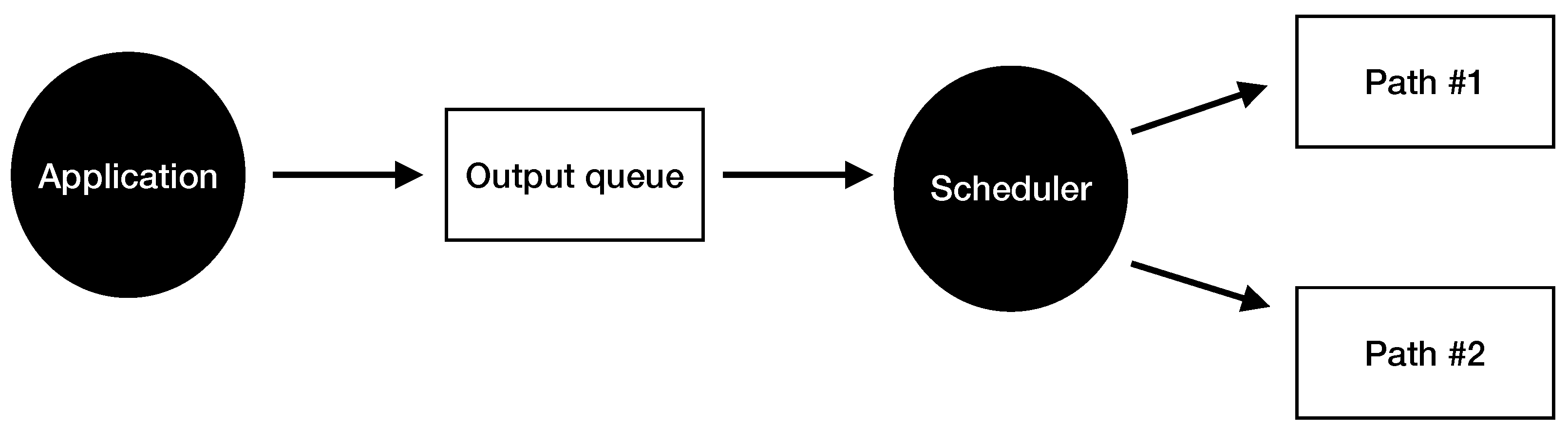
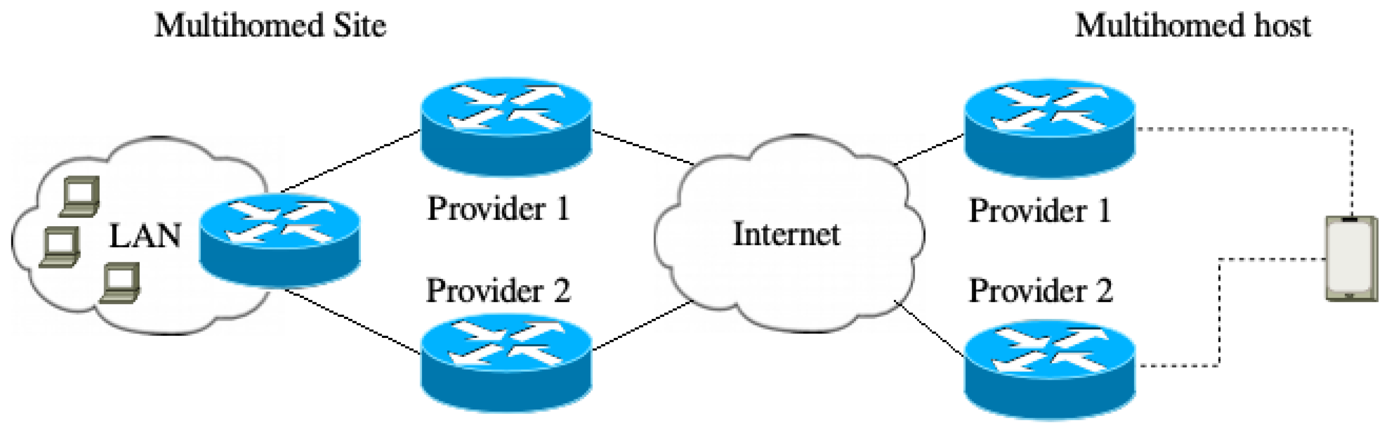
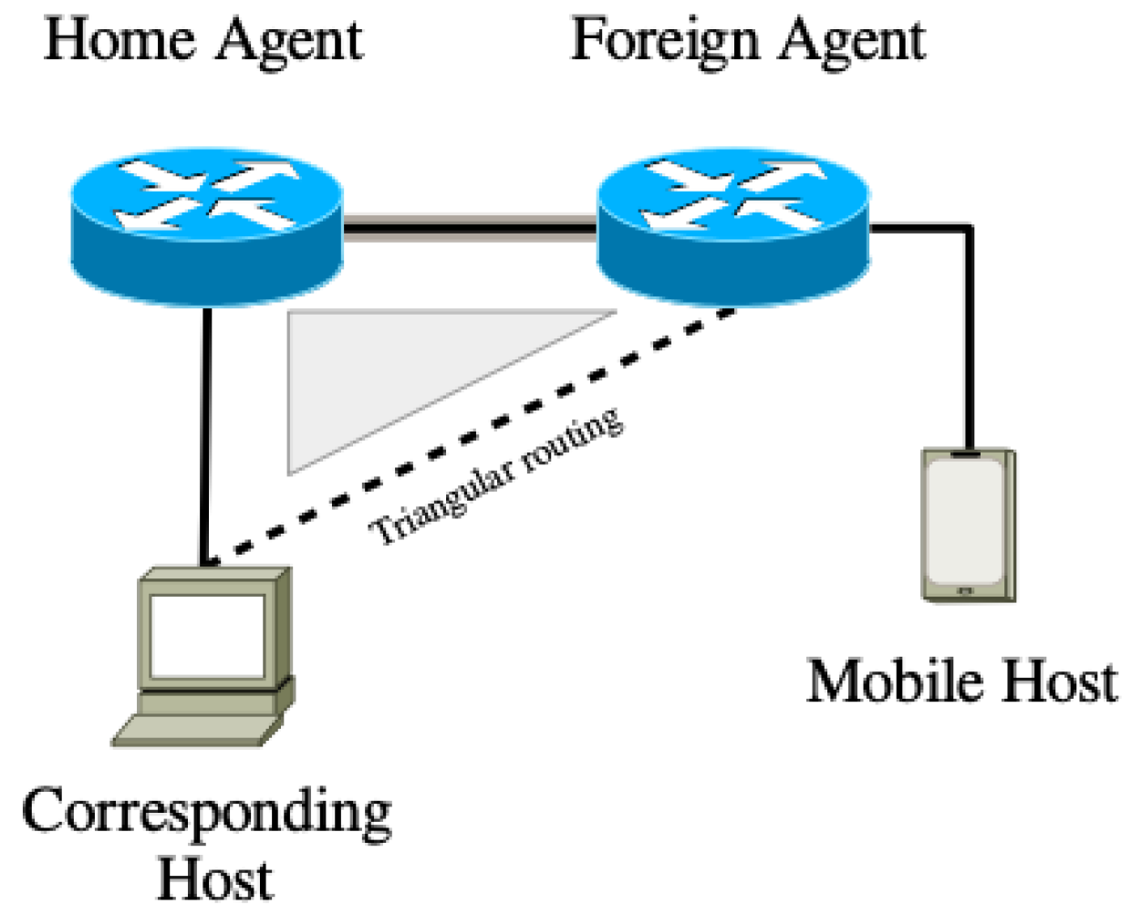
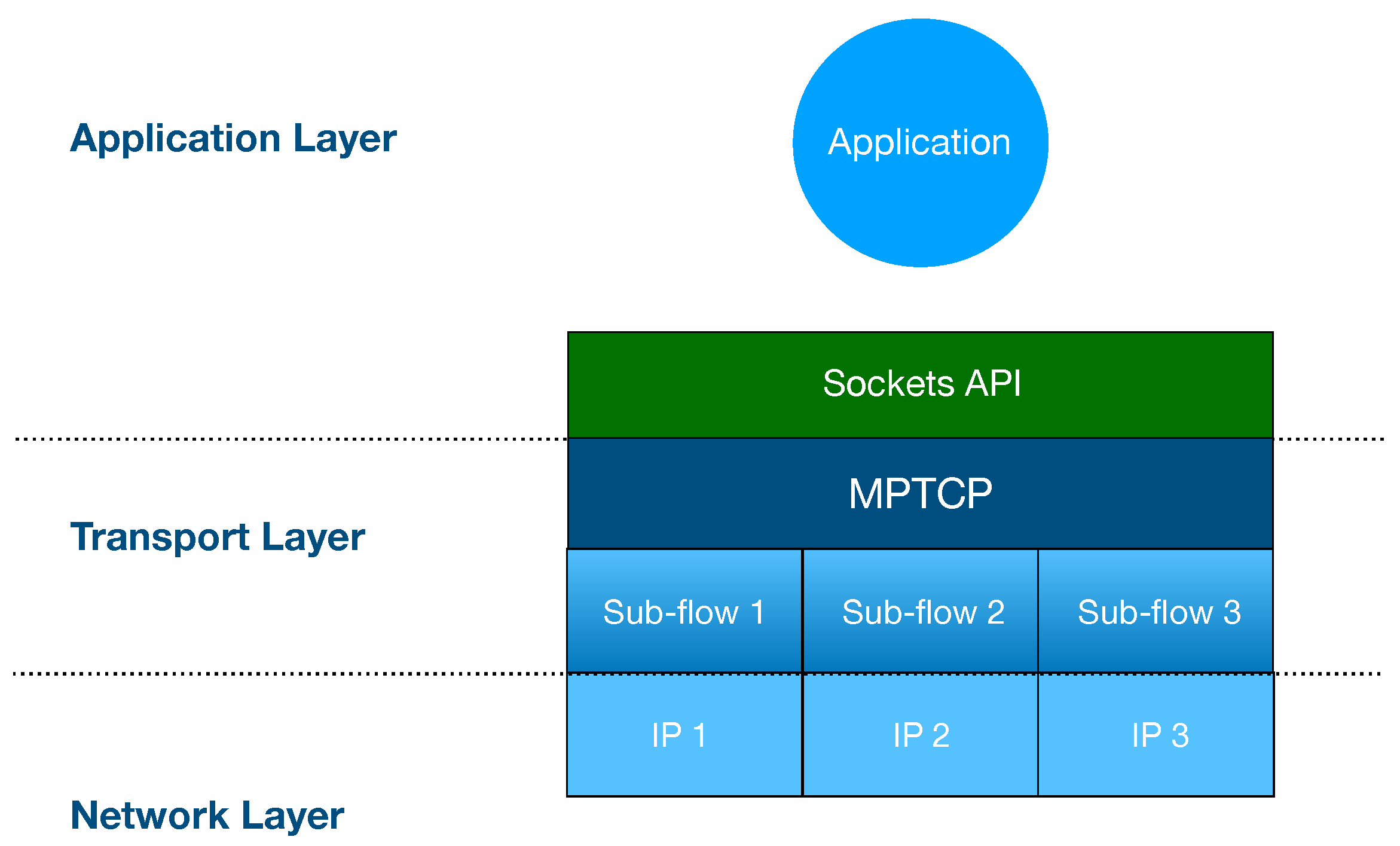
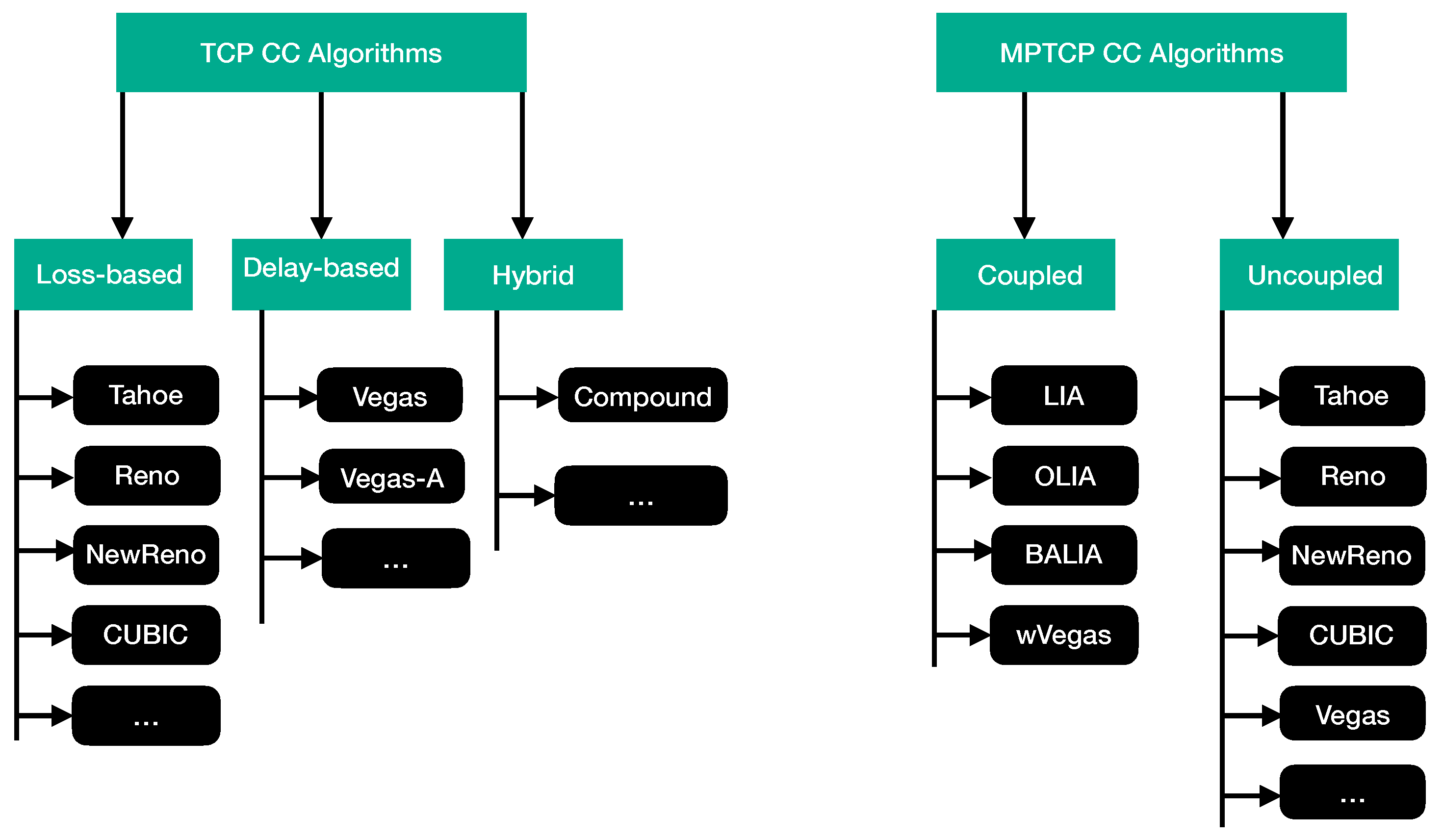
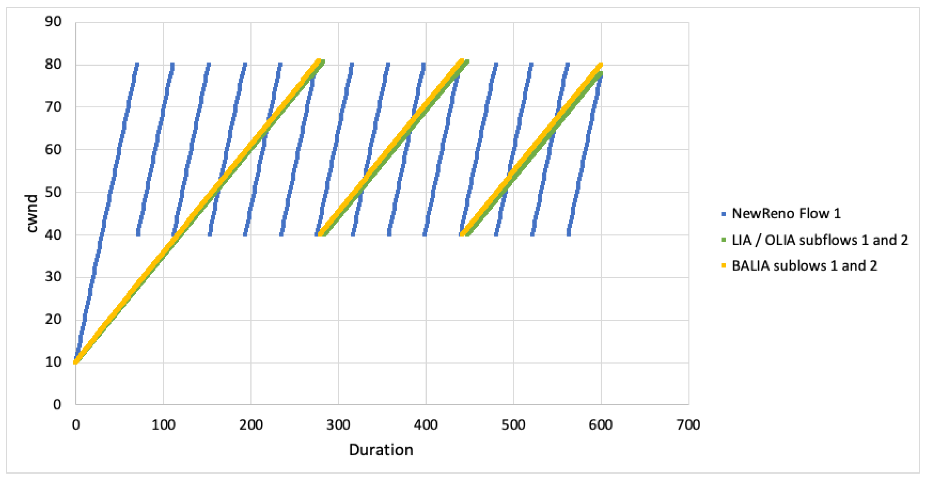
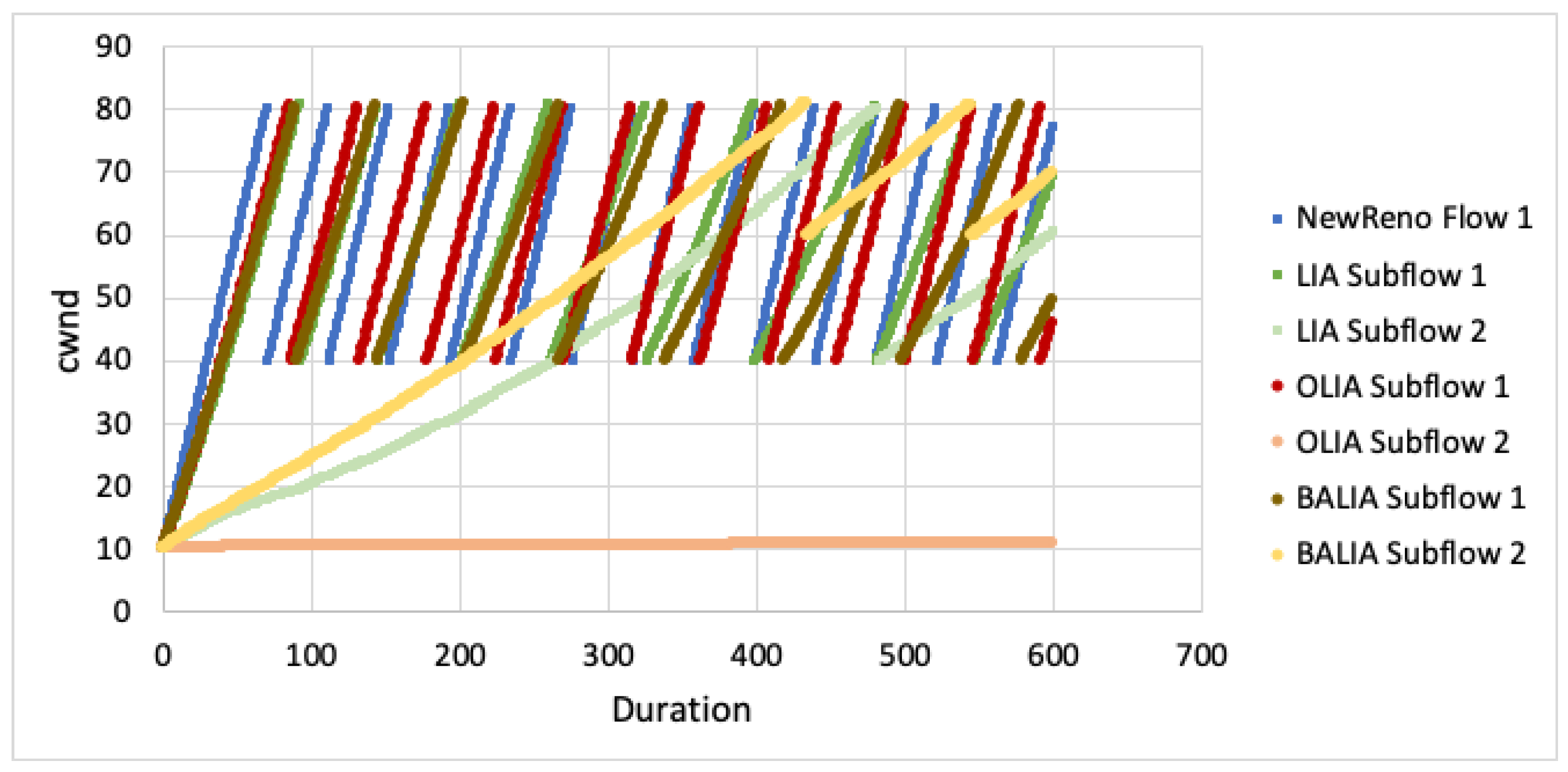
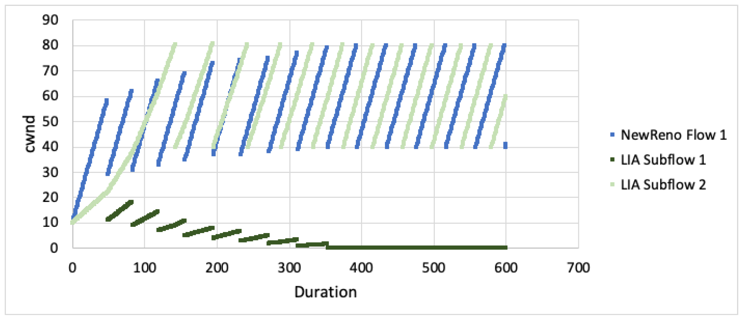
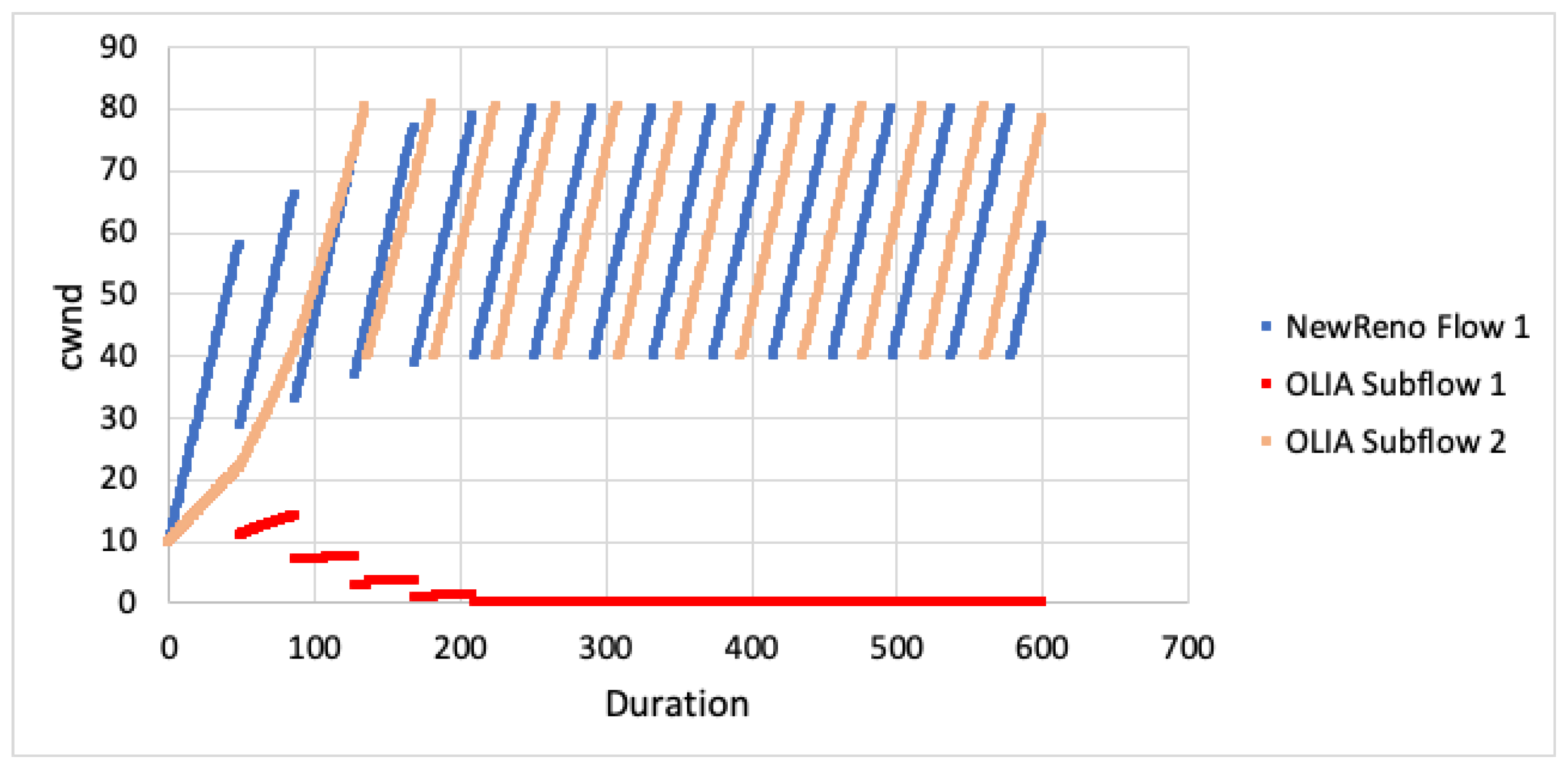
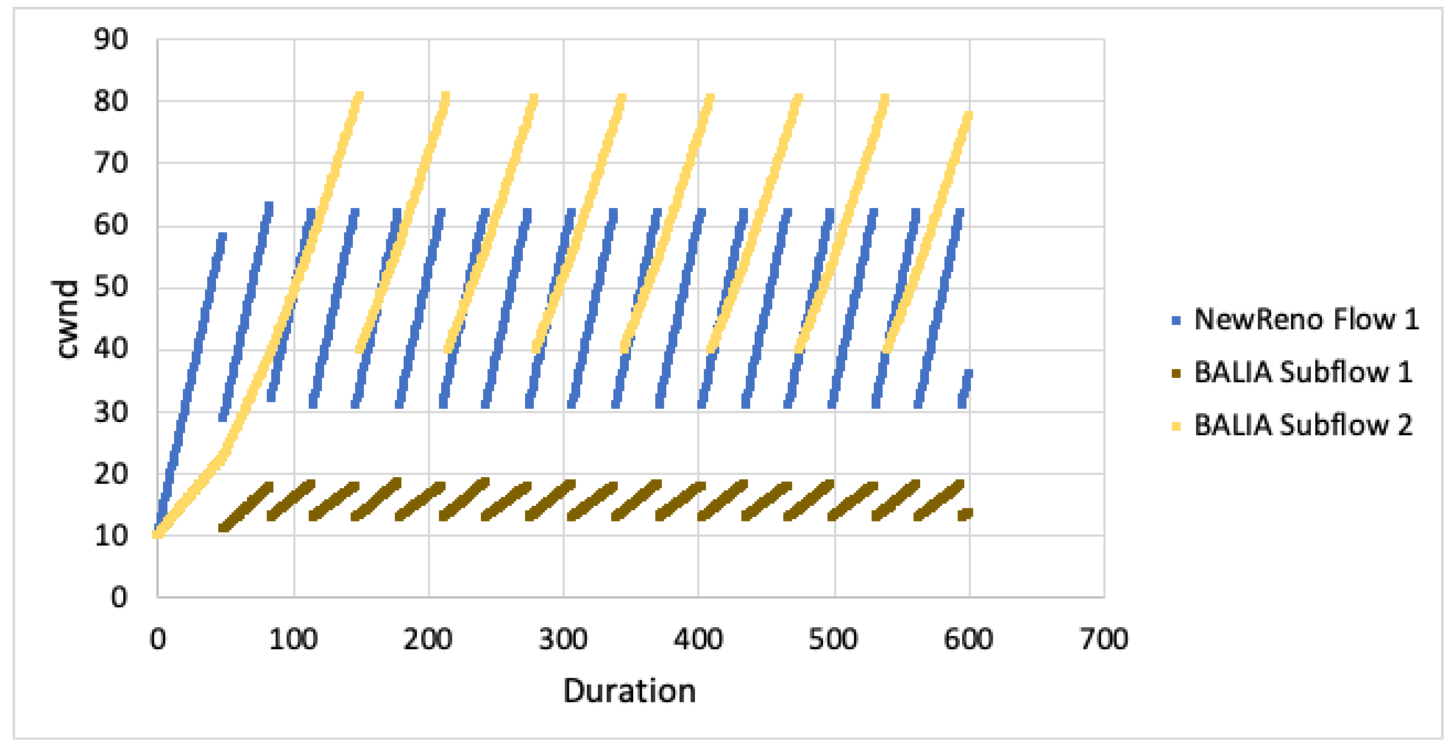
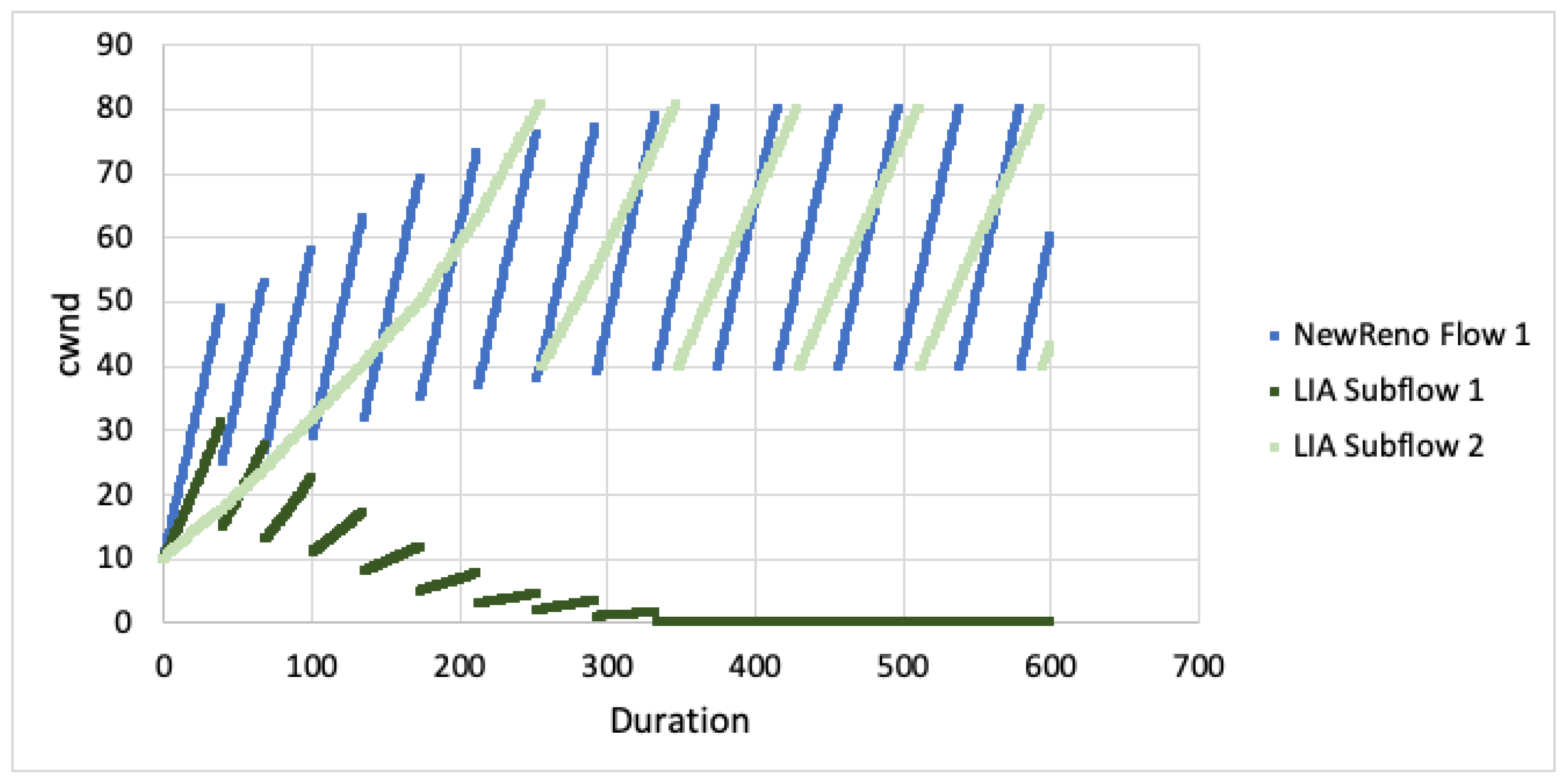
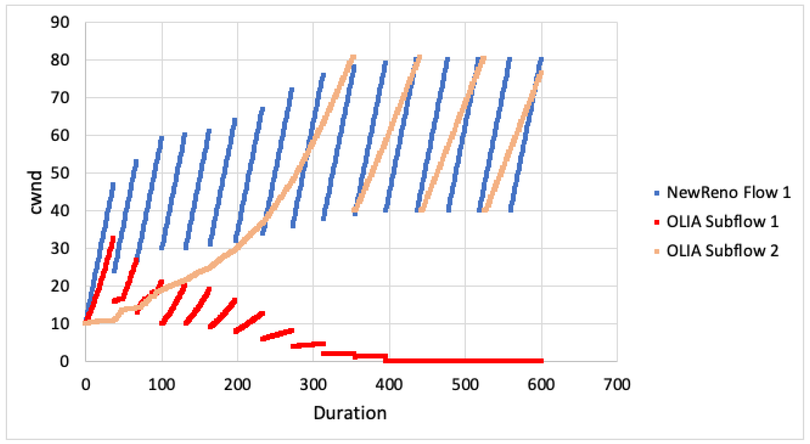
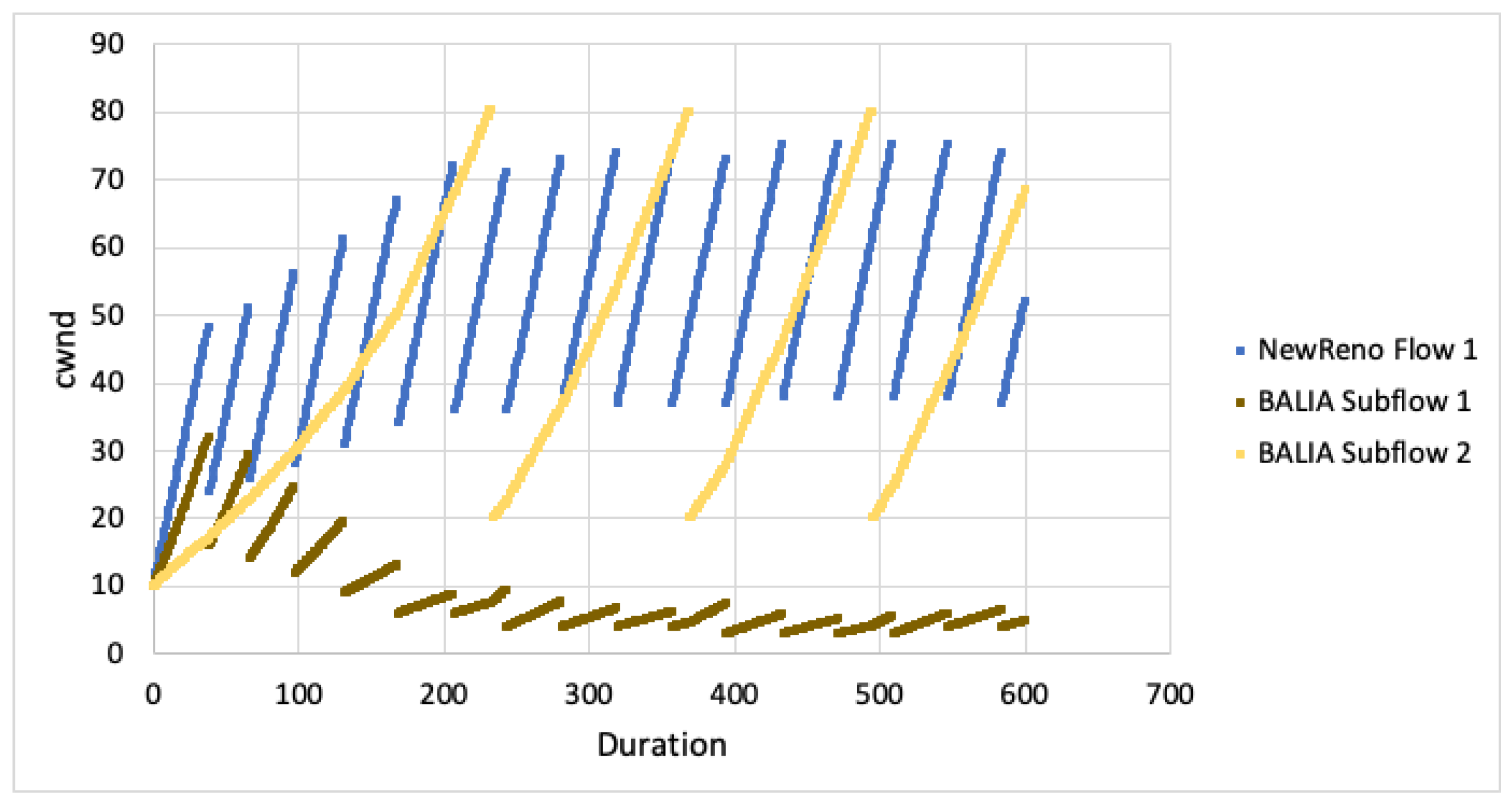
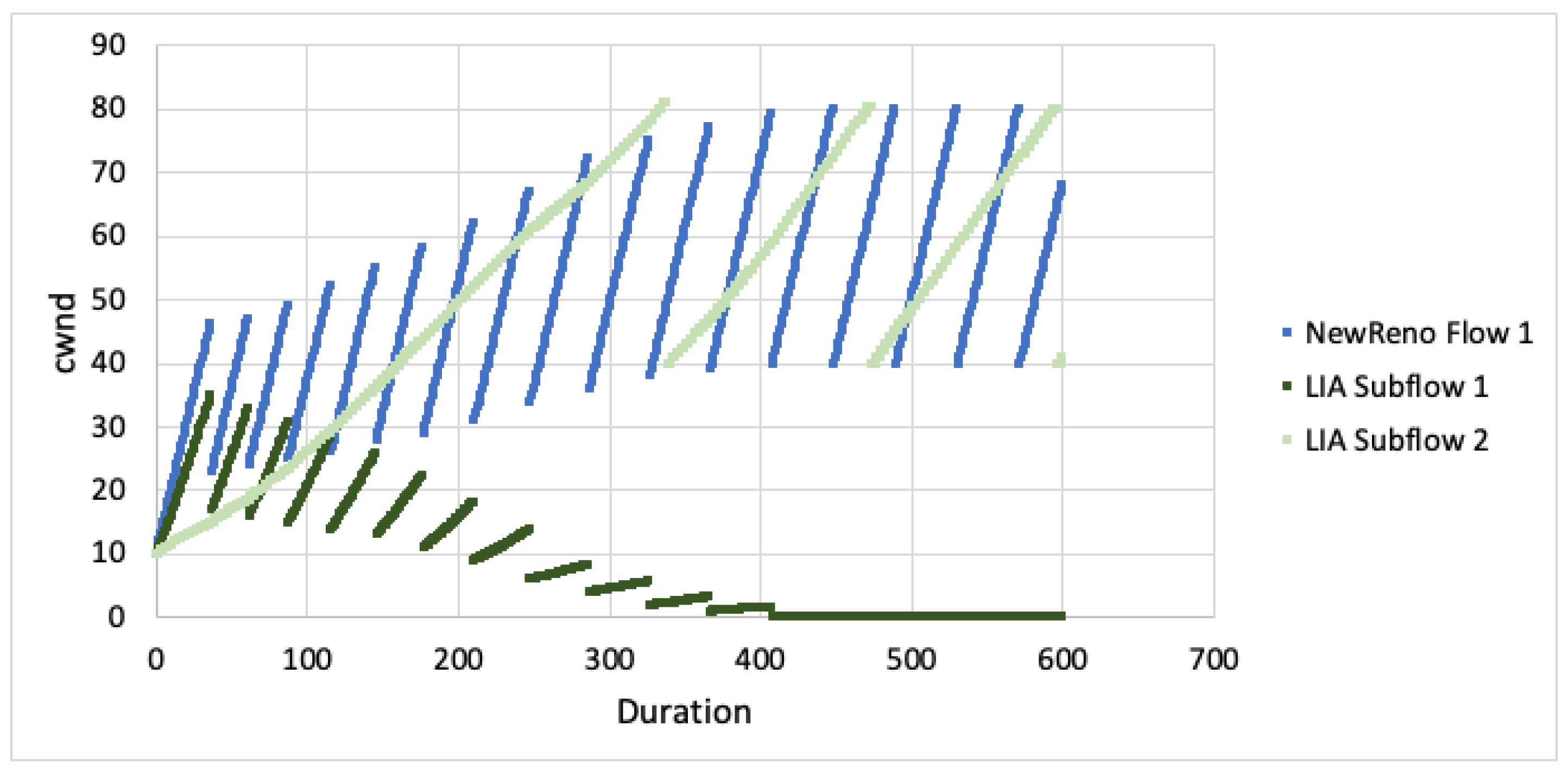
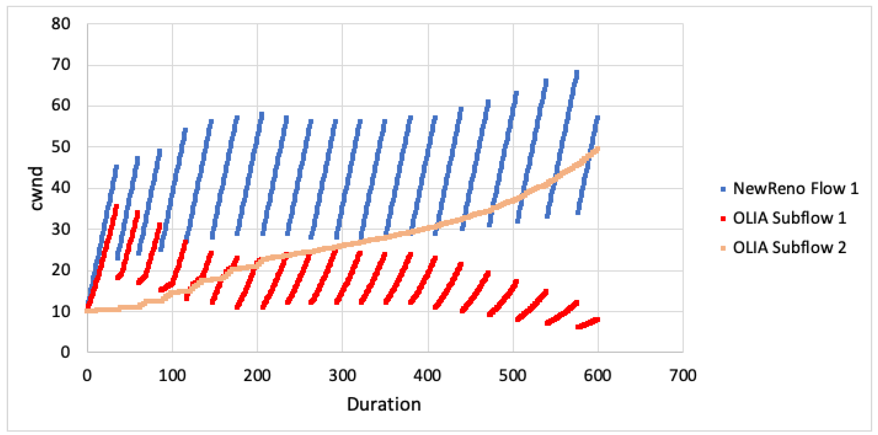
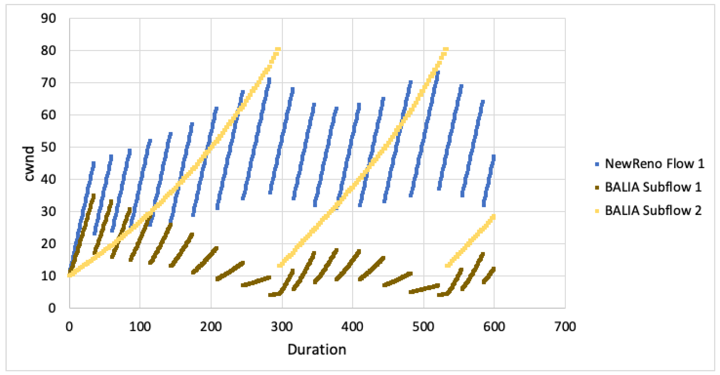
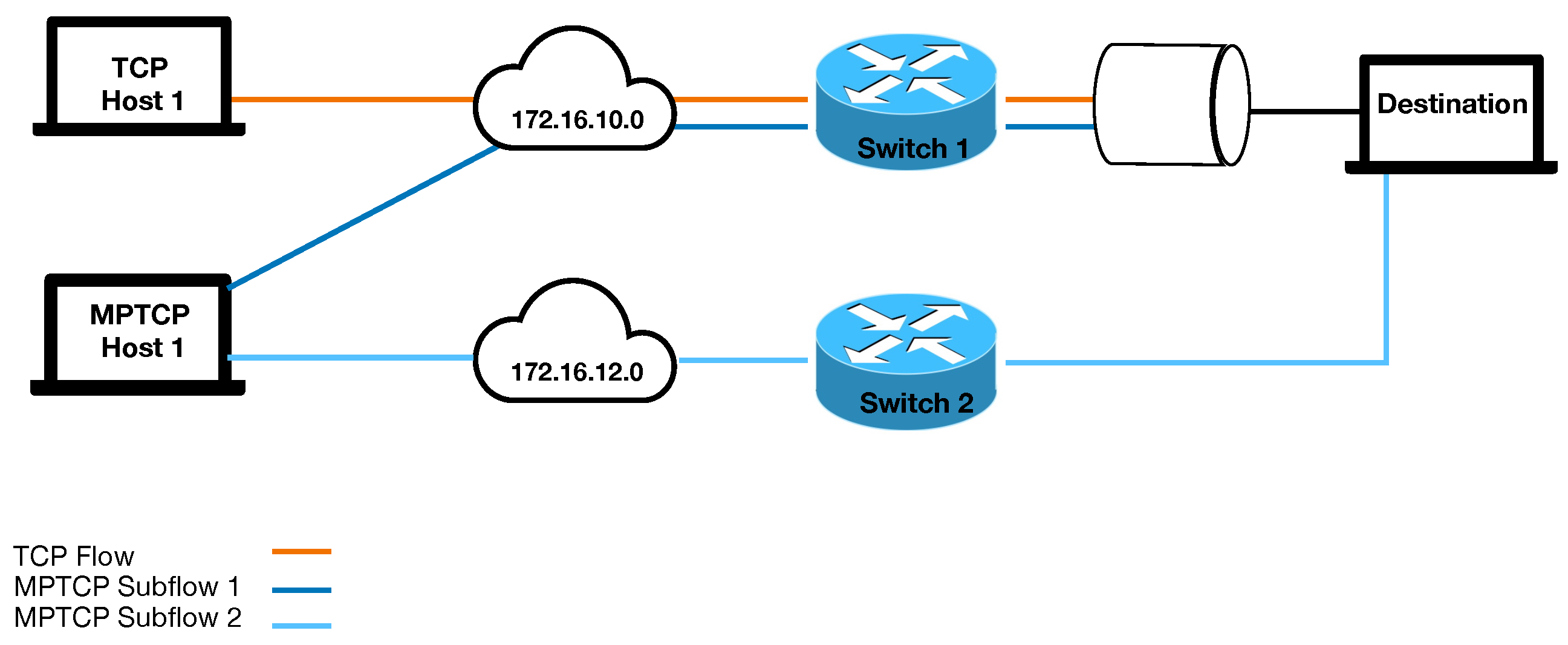
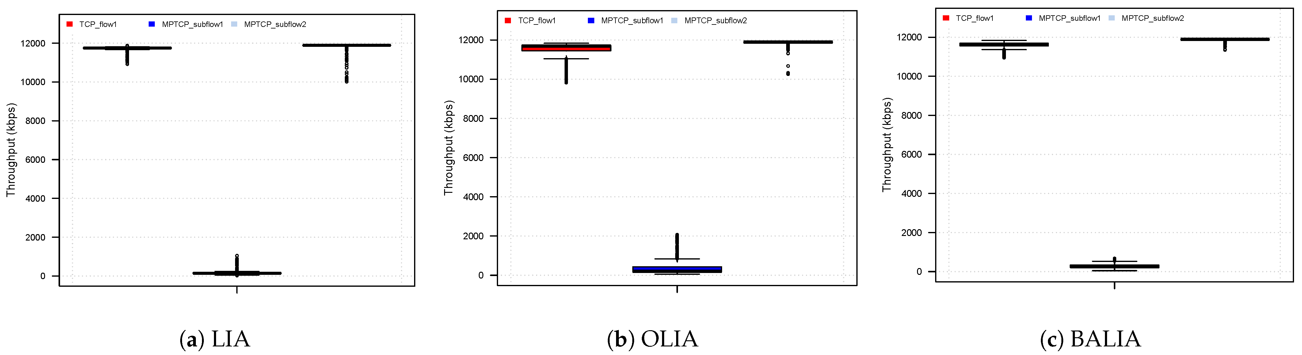
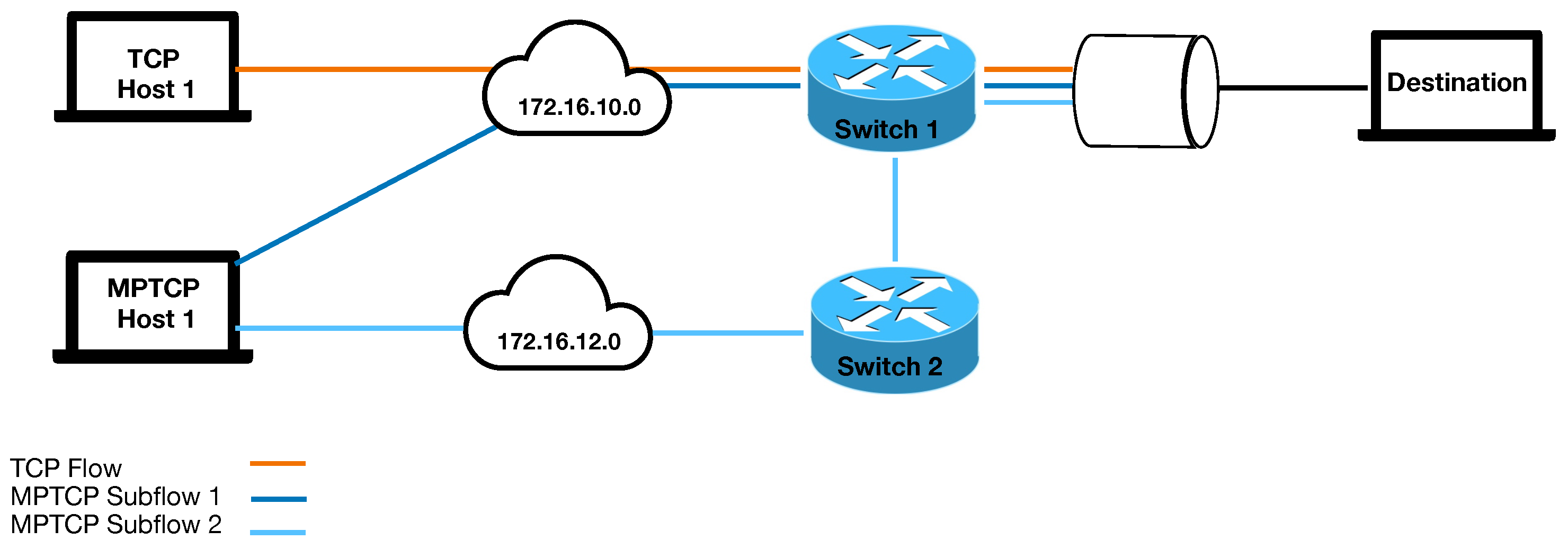
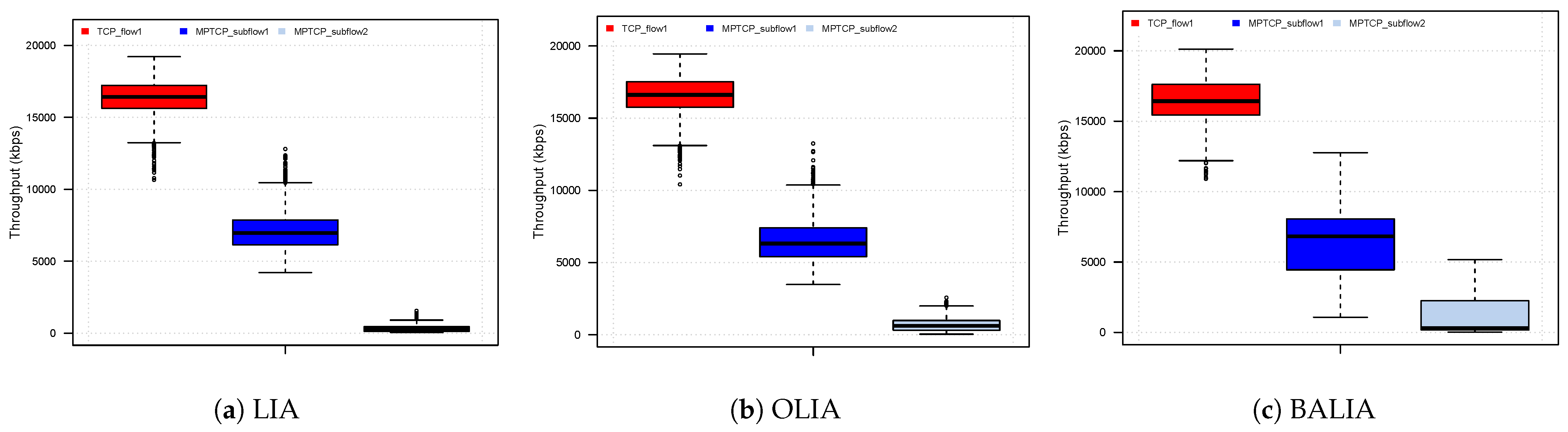
Table 1.
Main MPTCP Scheduling Solutions in Linux.
| Schedulers | Approach | Goals | Use-Cases |
|---|---|---|---|
| Minimum Round-Trip-Time First (minRTT) [25] | Default MPTCP scheduler in Linux which chooses the available subflow based on the lowest RTT | Improve throughput | Heterogenous networks |
| Round-Robin (RR) [25] | Transfer data on available subflows in round-robin fashion | Equal data distribution | Academic/Research/ Testing purposes |
| Redundant [25] | Transfer data on all available subflows in a redundant manner | Provide redundancy | Academic/Research/ Testing purposes |
| Weighted Round-Robin (WRR) [26] | Extension to RR scheduler - Allows sending data on different paths depending on the their weight value/priority | Prioritised data distribution/Optimise load balancing | Research/General applications |
| Shortest Transfer Time First (STTF) [27] | Distribute data on the subflows with shortest predicted transfer time | Reduce completion time | Web and interactive apps. |
| Highest Send Rate first (HSR) [28] | Select subflows with high sending rate | Improve throughput | Bulk transfer applications |
| Forward delay aware (DAPS) [29] | Uses RTTs to increase the in-order arrival at the receiver | Mitigate head-of-line blocking | Wireless networks |
| Lowest-latency with Retransmission and Penalisation scheduler (LL/RP) [11] | Penalising subflows that cause head-of-line blocking by | Mitigate head-of-line blocking | General applications |
| Lowest-latency with Bufferbloat Mitigation (LL/BM) [30] | An extension of LL which identifies subflows enqueued in the large buffer | Mitigate bufferbloat | General applications |
| Earliest Completion First (ECF) [31] | Investigate whether slower subflow affects faster subflow performance. Furthermore, assigns a packet to the faster subflow. | Improve quality of service | Video streaming applications |
| Out-of- Order Transmission for in order arrival (OTIAS) [30] | Estimates arrival time on all the paths and choose the fastest subflow. | Mitigate jitter | Real-time applications |
Table 2.
Share of 12 Mbps bandwidth attained at Switch One-Disjoint Paths.
| Path Bandwidth—12 Mbps | |||||||
|---|---|---|---|---|---|---|---|
| RTT Path 1 | 10 ms | 50 ms | |||||
| RTT Path 2 | 10 ms | 20 ms | 30 ms | 50 ms | 100 ms | 150 ms | |
| LIA | TCP | 125.6% | 107.4% | 132.0% | 183.2% | 195.6% | 195.8% |
| MPTCP Subflow 1 | 72.4% | 90.7% | 66.3% | 14.6% | 2.4% | 2.4% | |
| OLIA | TCP | 188.0% | 190.4% | 188.8% | 189.2% | 195.4% | 193.6% |
| MPTCP Subflow 1 | 10.0% | 7.6% | 9.4% | 7.4% | 2.8% | 4.6% | |
| BALIA | TCP | 149.0% | 134.6% | 127.0% | 184.0% | 193.8% | 193.6% |
| MPTCP Subflow 1 | 49.2% | 63.2% | 71.4% | 13.4% | 4.0% | 4.6% | |
Table 3.
Share of 24 Mbps bandwidth attained at Switch One-Disjoint Paths.
| Path Bandwidth—24 Mbps | |||||||
|---|---|---|---|---|---|---|---|
| RTT Path 1 | 10 ms | 50 ms | |||||
| RTT Path 2 | 10 ms | 20 ms | 30 ms | 50 ms | 100 ms | 150 ms | |
| LIA | TCP | 151.3% | 186.7% | 192.3% | 192.8% | 196.8% | 196.7% |
| MPTCP Subflow 1 | 46.8% | 11.5% | 5.8% | 5.0% | 1.4% | 1.4% | |
| OLIA | TCP | 192.6% | 192.8% | 192.9% | 191.9% | 196.4% | 196.0% |
| MPTCP Subflow 1 | 5.4% | 5.4% | 5.2% | 6.0% | 1.7% | 2.1% | |
| BALIA | TCP | 171.5% | 182.9% | 198.1% | 189.8% | 194.9% | 194.5% |
| MPTCP Subflow 1 | 26.4% | 15.2% | 12.2% | 7.8% | 3.2% | 3.6% | |
Table 4.
Share of 12 Mbps bandwidth attained at Switch One-Shared Paths.
| Path Bandwidth—12 Mbps | |||||||
|---|---|---|---|---|---|---|---|
| RTT Path 1 | 10 ms | 50 ms | |||||
| RTT Path 2 | 10 ms | 20 ms | 30 ms | 50 ms | 100 ms | 150 ms | |
| LIA | TCP | 79.4% | 87.6% | 90.8% | 105.6% | 127.4% | 138.0% |
| MPTCP Subflow 1 | 150.9% | 181.4% | 190.0% | 112.8% | 137.2% | 115.2% | |
| MPTCP Subflow 2 | 79.2% | 34.8% | 22.8% | 65.2% | 2.8% | 4.4% | |
| MPTCP Combined | 115.0% | 108.1% | 106.4% | 89.0% | 70.0% | 59.8% | |
| OLIA | TCP | 76.0% | 72.6% | 81.8% | 105.8% | 134.8% | 137.5% |
| MPTCP Subflow 1 | 217.5% | 236.8% | 224.0% | 162.4% | 117.2% | 114.0% | |
| MPTCP Subflow 2 | 23.2% | 13.6% | 8.8% | 9.6% | 8.4% | 8.4% | |
| MPTCP Combined | 120.3% | 125.2% | 116.4% | 86.0% | 62.8% | 61.2% | |
| BALIA | TCP | 75.4% | 89.2% | 82.5% | 107.0% | 131.4% | 140.0% |
| MPTCP Subflow 1 | 189.2% | 175.1% | 208.8% | 91.6% | 122.8% | 108.8% | |
| MPTCP Subflow 2 | 43.2% | 34.4% | 19.6% | 83.6% | 6.0% | 5.6% | |
| MPTCP Combined | 116.2% | 104.7% | 114.2% | 87.6% | 64.4% | 57.2% | |
Table 5.
Share of 24 Mbps bandwidth attained at Switch One-Shared Paths.
| Path Bandwidth—24 Mbps | |||||||
|---|---|---|---|---|---|---|---|
| RTT Path 1 | 10 ms | 50 ms | |||||
| RTT Path 2 | 10 ms | 20 ms | 30 ms | 50 ms | 100 ms | 150 ms | |
| LIA | TCP | 88.5% | 99.6% | 104.8% | 125.2% | 136.3% | 143.2% |
| MPTCP Subflow 1 | 85.6% | 178.1% | 175.4% | 42.8% | 116.8% | 106.6% | |
| MPTCP Subflow 2 | 123.4% | 14.8% | 10.0% | 96.2% | 4.6% | 2.0% | |
| MPTCP Combined | 104.5% | 96.5% | 92.7% | 69.5% | 60.7% | 54.3% | |
| OLIA | TCP | 92.4% | 89.4% | 98.4% | 121.6% | 137.2% | 146.9% |
| MPTCP Subflow 1 | 46.0% | 211.1% | 195.0% | 75.4% | 108.2% | 83.8% | |
| MPTCP Subflow 2 | 143.3% | 6.4% | 4.4% | 76.4% | 10.2% | 15.8% | |
| MPTCP Combined | 94.7% | 108.8% | 99.7% | 75.9% | 59.2% | 49.8% | |
| BALIA | TCP | 86.8% | 103.7% | 105.1% | 111.2% | 136.8% | 147.5% |
| MPTCP Subflow 1 | 78.1% | 170.9% | 173.2% | 123.8% | 109.3% | 93.0% | |
| MPTCP Subflow 2 | 139.3% | 16.8% | 10.4% | 36.6% | 5.2% | 6.8% | |
| MPTCP Combined | 108.7% | 93.9% | 91.8% | 80.2% | 57.3% | 49.9% | |
Publisher’s Note: MDPI stays neutral with regard to jurisdictional claims in published maps and institutional affiliations. |
© 2022 by the authors. Licensee MDPI, Basel, Switzerland. This article is an open access article distributed under the terms and conditions of the Creative Commons Attribution (CC BY) license (https://creativecommons.org/licenses/by/4.0/).
Share and Cite
MDPI and ACS Style
Jowkarishasaltaneh, F.; But, J. An Analysis of MPTCP Congestion Control. Telecom 2022, 3, 581-609. https://doi.org/10.3390/telecom3040033
AMA Style
Jowkarishasaltaneh F, But J. An Analysis of MPTCP Congestion Control. Telecom. 2022; 3(4):581-609. https://doi.org/10.3390/telecom3040033
Chicago/Turabian StyleJowkarishasaltaneh, Farinaz, and Jason But. 2022. "An Analysis of MPTCP Congestion Control" Telecom 3, no. 4: 581-609. https://doi.org/10.3390/telecom3040033