Article

Low-Computational Extended Orthogonal Matched Filter Structure for Multiuser Detection

1
Department of Information and Communication Engineering, Faculty of Computer Science and Systems Engineering, Okayama Prefectural University, Okayama 719-1197, Japan
2
Faculty of Engineering, Yokohama National University, Yokohama 240-8501, Japan
*
Author to whom correspondence should be addressed.
Telecom 2020, 1(1), 32-47; https://doi.org/10.3390/telecom1010004
Submission received: 20 May 2020 / Revised: 7 June 2020 / Accepted: 9 June 2020 / Published: 11 June 2020
(This article belongs to the Special Issue Recent Advances in Smart and Pervasive Internet of Things)

Abstract

:
This research provides a novel extended orthogonal matched filter (EOMF) structure that supports multiuser detection. In addition, this structure is designed to suppress increases in computational complexity and circuit scale. In coming years, the number of Internet of Things (IoT) applications that use wireless ad hoc networks is expected to increase. To realize a highly reliable wireless ad hoc network, it is essential to introduce a method for cancelling the interference from other users. This research adopts a method based on code division multiple access (CDMA). However, a CDMA-based method has difficulty with deteriorating performance due to the near-far problem and the increase in the amount of interference as the number of users increases. Another problem is that the spreading sequence of each user is unknown in a wireless ad hoc network. The EOMF effectively removes interference while solving the above problems by combining an OMF and an adaptive array antenna. In this research, an EOMF structure with multiuser detection and lower computational complexity than the conventional EOMF is proposed. By the derived formulas and numerical examples, the proposed structure reduces the computational complexity by approximately 75% compared to the conventional EOMF and obtains sufficient bit error ratio (BER) performance.

Graphical Abstract

1. Introduction

With the advent of the Internet of Things (IoT), industry and people’s lives have undergone major changes [1,2,3,4]. The IoT connects various devices, such as sensors, actuators, cars, and unmanned aerial vehicles (UAVs), to the network. In a world where IoT has become the norm, its role as an infrastructure is becoming increasingly important, requiring more reliability and efficiency than ever before. There are also a wide variety of applications that use the IoT. In particular, for applications with limited battery capacity, such as sensors and UAVs, the associated wireless communication systems require low latency, low cost, and low energy consumption [3,4].
One of the important technologies for realizing an IoT system is a wireless ad hoc network [5,6,7,8,9]. A wireless ad hoc network is a network consisting of only users who do not need a wireless communication base station. In coming years, vehicle-to-vehicle networks (vehicular ad hoc network: VANET), networks using UAVs and mobile terminals in the event of a disaster, and other networks are expected to be applications of wireless ad hoc networks. To realize a highly reliable wireless ad hoc network, it is essential to introduce a method for cancelling the interference from other users because the network cannot use the transmission power control and interference avoidance techniques of base stations and access points. Our research focuses on a scheme based on code division multiple access (CDMA) [10,11,12,13]. CDMA is well known due to its use in third-generation cellular systems. In it, each user is assigned a different spreading sequence, and the orthogonality of the different sequences is used to identify the user. CDMA also enables simultaneous multiple access and low latency communication [10,11,12,13]. For example, the performances of the CDMA scheme and the orthogonal frequency division multiplexing (OFDM) scheme assuming VANET are evaluated [13]. In addition, it is shown that the CDMA scheme has lower latency communication than the OFDM scheme [13]. However, there are problems with deteriorating performance due to the near-far problem and the increase in the amount of interference as the number of users increases [10,11,12,13]. Another problem is that the spreading sequence of each user is unknown in a wireless ad hoc network [10,11,12,13]. The orthogonal matched filter (OMF) has been applied to solve this problem [14,15,16,17]. The OMF cancels interference by generating and subtracting a replica of the interference signal contained in the received signal [14,15,16,17]. For example, an interference cancellation method using concatenated spreading sequences and a layered OMF to support different period spreading sequences is proposed [14]. A space temporal interference cancellation method for ultra-wideband (UWB) communication systems based on the combination of a tapped delay line array antenna and an OMF is provided since impulse radio UWB does not have a carrier signal [15]. An inter-user and inter-system interference mitigation method using a combination of an orthogonal pulse shape modulation and an OMF detector is proposed [16]. The system aims to detect all signals of users in the same UWB system and to reduce the unknown interference from other UWB systems at the same time. The authors of [17] introduces an interference mitigation method using an OMF based on the modified Hermite polynomials for an impulse radio UWB system, and provides the performance bound and the optimal parameter. An OMF method is suitable for wireless ad hoc networks because it can generate a replica of the interfering signal contained in the received signal, even if the spreading sequence used by the interfering user is unknown. However, if the desired signal-to-interference signal ratio (DIR) is small (i.e., in the case of a near-far problem), the OMF will produce a false replica, resulting in poor performance. Therefore, an extended OMF (EOMF) combining an adaptive array antenna and the OMF are devised [18]. First, the EOMF spatially cancels the interference with an adaptive array antenna. Then, the OMF suppresses the residual interference signal. It was shown that the EOMF improved the error convergence of the adaptive algorithm and compared the effectiveness of the EOMF with the conventional interference cancellation method by a computer simulation [18]. In addition, the optimum parameters through mathematical modeling and theoretical analysis of the EOMF were derived [19].
In fact, the EOMF cannot detect signals from multiple users due to its structure. That is, it does not support multiple user detection. Even in the environment of a wireless ad hoc network, there may be situations in which the spreading sequences of multiple users are known. Hence, multiuser detection may be necessary to improve communication quality and network capacity. When a conventional EOMF is prepared for the number of desired users and multiuser detection is performed, the computational complexity (multiplication, addition/subtraction, total sum of products) increases in proportion to the number of desired users and, at the same time, the circuit scale increases. When assuming IoT applications with limited hardware scale and battery capacity, such as a mobile robot that collects various data from sensors in the factory and a monitoring system using a wireless ad hoc network formed by UAVs, the computational complexity and circuit scale should be as small as possible. The purpose of this research is to design a novel EOMF structure that supports multiuser detection and that can suppress an increase in the computational complexity and the circuit scale. This research contributes to the construction of highly reliable and energy-efficient wireless ad hoc networks for IoT applications for which there are many users.
The remainder of this paper is organized as follows. In Section 2, the principle of the EOMF is summarized. In Section 3, the proposed structure of the EOMF is described, and the computational complexity is compared with that of a conventional EOMF. Performance evaluations are provided in Section 4. Conclusions and suggestions for future research are presented in Section 5.

2. Principle of the EOMF

2.1. Formulation of an EOMF

This section describes the principle of the EOMF [18,19]. Figure 1 shows the basic structure of an EOMF [18,19]. In the case in which the weight vector of the array antenna when beamforming has the desired signal U [ U 1 ,   U 2 ,   ,   U K ] T , the signal y beam that enters matched filter 1 ( MF 1 ) is described by Equations (1)–(3):
y beam = k = 1 K R e { U k * x k } = k = 1 K ( m = 1 M P m d m c m R e { e j ϕ k ( θ m ) U k * } + R e { n k U k * } )
x k = m = 1 M P m d m c m e j ϕ k ( θ m ) + n k
ϕ k ( θ m ) = 2 π λ R cos { θ m 2 π K ( k 1 ) } .
Here, K is the number of antenna arrays, M is the total number of nodes, d m {−1, 1} is the modulated data symbol for the binary phase shift keying (BPSK), c m = [ c m ( 1 ) ,   c m ( 2 ) ,   ,   c m ( N ) ] T is the spreading sequence of the m -th node for the direct-sequence spread-spectrum (DSSS), P m is the transmitted signal power of the m -th node, θ m is the angle of arrival of the signal at the m -th node, R is the radius of the circular array antenna, λ is the wavelength of the radio wave, T is the transposition, is the complex conjugate, and n k is the noise component generated in the channel for the N chips. Similarly, in the case in which the weight vector of the array antenna when null-steering the desired signal is V [ V 1 ,   V 2 ,   ,   V K ] T , the signal y null that enters the matched filter group (MFG: MF 2 ,   ,   MF N ) is as follows in Equation (4):
y null = k = 1 K R e { V k * x k } = k = 1 K ( m = 1 M P m d m c m R e { e j ϕ k ( θ m ) V k * } + R e { n k V k * } ) .
Then, the output signal of the MF 1 y MF 1 is expressed by Equation (5):
y MF 1 = c 1 T y beam = k = 1 K ( N P 1 d 1 R e { e j ϕ k ( θ 1 ) U k * } + m = 2 M P m d m c 1 T c m R e { e j ϕ k ( θ m ) U k * } + c 1 T R e { n k U k * } ) .
In (5), the first term, the second term and the third term represent the desired signal component, the interference signal component, and the noise component, respectively. Additionally, the output signal of the MF i ( i = 2 ,   ,   N ) , y MF i , is expressed as follows in Equation (6):
y MF i = u i T y null = k = 1 K ( m = 2 M P m d m u i T c m R e { e j ϕ k ( θ m ) V k * } + u i T R e { n k V k * } ) .
Here, u i = [ u i ( 1 ) ,   u i ( 2 ) ,   ,   u i ( N ) ] is a sequence that is orthogonal to c 1 , which is generated by Gram–Schmidt orthonormalization. In fact, y MF 1 and y MF i must be normalized with respect to the desired signal component because the error signal to update the weight vector w [ w 1 ,   w 2 ,   ,   w N 1 ] T of the linear combiner (LC) is the difference between the output of the EOMF and its hard decision signal. Hence, Equation (7) must hold:
| k = 1 K N P 1 d 1 R e { e j ϕ k ( θ 1 ) U k * } k = 1 K N P 1 R e { e j ϕ k ( θ 1 ) U k * } | = | d 1 | = 1 .
In this study, Equation (7) is assumed to hold for the sake of simplification. Assuming that the normalized y MF 1 and y MF i are y MF 1 = y MF 1 α and y MF i = y MF i α , respectively, the output of the EOMF y is expressed as follows in Equation (8):
y = y MF 1 + i = 1 N 1 w i y MF i + 1 = 1 α ( y MF 1 + i = 1 N 1 w i y MF i ) ,   ( α 0 ) .
Thus, the interference is achieved by adaptively controlling the weight vector in such a way that any sum other than the first term approaches zero in the LC. This study uses a normalized least mean square (NLMS) algorithm to update the array antenna and the LC weights, as in previous studies [19]. The NLMS is a method to update the step size μ of the LMS algorithm at each sample point, which can converge in the same way faster than the LMS algorithm. The step size of the NLMS is fixed in the range of 0 < μ < 2. When using the NLMS, the update equations for the array antenna weight vector and the LC weight vector are given by Equations (9)–(11):
U ( t + 1 ) = U ( t ) + μ e U * ( t ) x ( t ) x ( t ) 2
V ( t + 1 ) = V ( t ) + μ e V * ( t ) x ( t ) x ( t ) 2
w ( t + 1 ) = w ( t ) + μ e LC * ( t ) y MF i ( t ) y MF i ( t ) 2 .
Here, the error signals used to update the antenna weights e U and e V are given as follows in Equations (12) and (13), respectively:
e U ( t ) = d U ( t ) y beam ( t )
e V ( t ) = d V ( t ) y null ( t )
where d U ( t ) is the reference signal and d V ( t ) is the subtraction of d U ( t ) from the received signal. Then, an error signal used to update the LC weights e LC is given as follows in Equations (14) and (15):
y ( t ) = y MF 1 ( t ) I replica ( t )
e LC ( t ) = y ( t ) Y ( t )
where y ( t ) and I replica ( t ) are the EOMF output and the replica of the interference component, respectively, and Y ( t ) is the hard decision value of y ( t ) .

2.2. Computational Complexity of an EOMF

Table 1 summarizes the computation in the EOMF and its computational complexity. In addition, the computational complexity of the NLMS algorithm is summarized in Table 2 from the calculation of the weight U for beamforming. Here, X is an input vector of the circular array antenna, and H is the complex conjugate transposition. By multiplying and adding weights, the computational complexity of the number of weights is required from Table 1. Additionally, the computational complexity of the spreading sequence length is required to calculate the correlation values of MF. Since the required number of MFs is the spreading sequence length N , the computational complexity of N 2 is required from (c) and (d) in Table 1. Furthermore, the computational complexity of the NLMS algorithm is 2 K when obtaining the beamforming weights for the number of antenna elements K from Table 2. The computational complexity is the same in the case of null steering. The computational complexity of the NLMS algorithm is 2( N 1 ) since the length of the LC weight vector in the OMF is N 1 . Thus, the computational complexity of the EOMF, C EOMF is as follows in Equation (16):
C EOMF = K + K + N 2 + ( N 1 ) + 2 K + 2 K + 2 ( N 1 ) = N 2 + 3 N 3 + 6 K

3. Proposed EOMF Structure

3.1. Approach to an EOMF with Multiuser Detection

From Equation (16), N 2 greatly affects the computational complexity of the EOMF, in other words, the sum of the correlation value calculations of each MF. In the case in which the total number of desired users is M d , when multiuser detection is performed by using M d ordinary EOMFs, N 2 is multiplied by M d , and the computational complexity increases significantly. In addition, the circuit scale also increases since the number of MFs is M d times. Hence, it is necessary to detect multiple users without increasing the number of MFs.
First, the spreading sequence of the desired user is necessary to detect multiple users. If the desired user is m d ( m d = 1, 2, …, M d ), then an MF with the same sequence as the spreading sequence c m d is required. On the other hand, sequences of MFs other than MF m d that have the spreading sequence c m d must be orthogonal to c m d in the case of multiuser detection. Thus, it is assumed that MF m d has a spreading sequence of desired users m d , and MF m ( m = M d + 1 , …, N ) has a sequence that is orthogonal to the spreading sequence of the desired users, as generated by the Gram–Schmidt orthonormalization. Next, it is considered that M d LCs are required to generate the interference replicas. Finally, with regard to beamforming and null steering in the adaptive array antenna, it is considered to be necessary to individually perform M d desired users. Hence, the weight vector U m d = [ U 1 m d ,   U 2 m d ,   ,   U K m d ] T for beamforming for the desired user m d is obtained by M d NLMS algorithms. In addition, null steering is performed to accelerate the convergence of the error in the LC. This step is performed simultaneously for the desired user m d , and the output is input to MF m . Although multiple desired signals are suppressed, the performance is expected to improve even if it is inferior to conventional EOMF suppression.

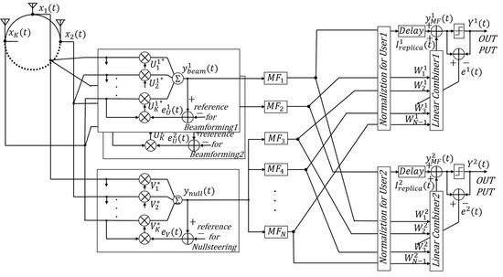
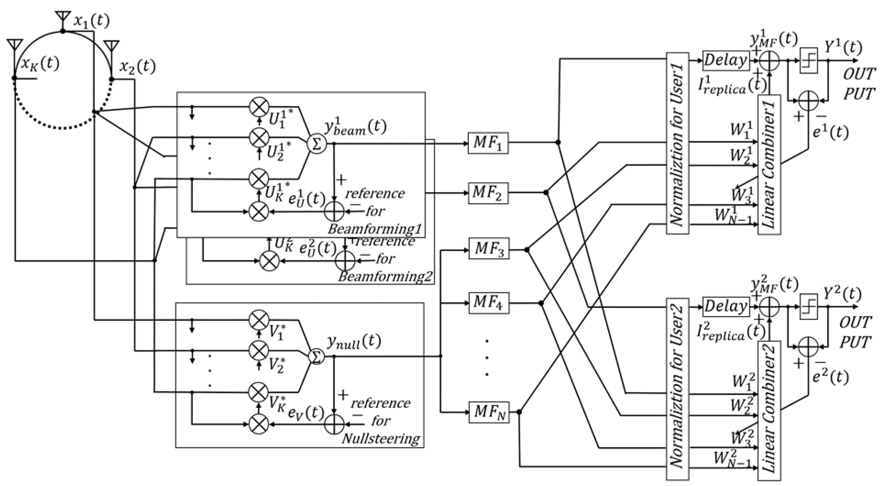
3.2. Structure of an EOMF with Multiuser Detection

Figure 2 shows the proposed system structure for two-user detection (desired users 1 and 2). When the number of desired users is two, MF 1 and MF 2 have the same sequences as the spreading sequences of desired users 1 and 2, respectively. Then, the beamformed antenna outputs for desired user 1 and desired user 2 are input to MF 1 and MF 2 , respectively. MF 3 to MF N have sequences that are orthogonal to the spreading sequences of desired users 1 and 2, as generated by Gram–Schmidt orthonormalization. To improve the error convergence characteristic in the adaptive algorithm, the null-steered antenna outputs for desired users 1 and 2 are input to MF 3 to MF N . In LC 1, the output of MF other than MF 1 is weighted and added to generate a replica of interference for desired user 1, which is included in the output of MF 1 . By using this approach, the interference is removed from the MF 1 output. The same approach can be used for LC 2.
The features of the proposed structure are described from the viewpoint of IoT applications. The proposed structure reduces the number of MFs, which has the largest amount of calculation in the system, compared to the conventional EOMF. That is, the energy consumption is reduced by the amount of the reduced computational complexity. On the other hand, the number of LCs and the number of adaptive array antenna taps are not changed significantly compared to the conventional EOMF. The LMS algorithm to update the array antenna and the LC weights is sufficiently energy efficient to be used in wireless sensor networks due to its simplicity [20,21,22]. Hence, it can be said that the proposed structure is more suitable for IoT applications that require energy savings than the conventional EOMF.
The operation of the proposed system is explained using mathematical expressions. Letting U 1 = [ U 1 1 ,   U 2 1 ,   ,   U K 1 ] T , U 2 = [ U 1 2 ,   U 2 2 ,   ,   U K 2 ] T be the weight vector of the array antenna for beamforming for desired users 1 and 2, respectively, the signals input to MF 1 and MF 2 are as follows in Equations (17) and (18):
y beam 1 = R e { ( U 1 ) H X } = k = 1 K R e { ( U k 1 ) * x k ( t ) }
y beam 2 = R e { ( U 2 ) H X } = k = 1 K R e { ( U k 2 ) * x k ( t ) } .
Then, the received signal vectors y beam 1 and y beam 2 of MF 1 and MF 2 obtained by sampling y beam 1 and y beam 2 for N chips are as follows in Equations (19) and (20), respectively:
y beam 1 = k = 1 K R e { ( U k 1 ) * x k } = k = 1 K ( m = 1 M P m d m c m R e { e j ϕ k ( θ m ) ( U k 1 ) * } + R e { n k ( U k 1 ) * } )
y beam 2 = k = 1 K R e { ( U k 2 ) * x k } = k = 1 K ( m = 1 M P m d m c m R e { e j ϕ k ( θ m ) ( U k 2 ) * } + R e { n k ( U k 2 ) * } ) .
The signal vector y null input to MF 3 to MF N is the same as in Equation (4) when the weight vector of the array antenna for null steering for desired users 1 and 2 is V = [ V 1 ,   V 2 , , V K ] T . From the above, the output signals y MF 1 and y MF 2 of MF 1 and MF 2 are as follows in Equations (21) and (22), respectively:
y MF 1 = c 1 T y beam 1 = k = 1 K ( N P 1 d 1 R e { e j ϕ k ( θ 1 ) ( U k 1 ) * } + m 1 M P m d m c 1 T c m R e { e j ϕ k ( θ m ) ( U k 1 ) * } + c 1 T R e { n k ( U k 1 ) * } )
y MF 2 = c 2 T y beam 2 = k = 1 K ( N P 2 d 2 R e { e j ϕ k ( θ 2 ) ( U k 2 ) * } + m 2 M P m d m c 2 T c m R e { e j ϕ k ( θ m ) ( U k 2 ) * } + c 2 T R e { n k ( U k 2 ) * } ) .
The output signal of MF i , y MF i , ( i = 3 ,   4 ,   ,   N ) is as follows in Equation (23):
y MF i = u i T y null = k = 1 K ( m = 3 M P m d m u i T c m R e { e j ϕ k ( θ m ) V k * } + u i T R e { n k V k * } ) .
The conventional EOMF normalizes the desired signal component before inputting the signal to MF, while the desired signal component of each desired user is normalized before inputting to each LC in the proposed structure. The reason is that there are multiple desired users. The values α 1 and α 2 for normalizing the desired user signals 1 and 2 are as follows in Equations (24) and (25), respectively:
α 1 = k = 1 K N P 1 R e { e j ϕ k ( θ 1 ) ( U k 1 ) * }
α 2 = k = 1 K N P 2 R e { e j ϕ k ( θ 2 ) ( U k 2 ) * } .
Letting y MF 1 , y MF 2 , and y MF i be normalized for desired user 1 yields y MF 1 1 , y MF 2 1 , and y MF i 1 ; these are expressed by Equations (26)–(28), respectively:
y MF 1 1 = y MF 1 α 1 = c 1 T y beam 1 α 1
y MF 2 1 = y MF 2 α 1 = c 2 T y beam 2 α 1
y MF i 1 = y MF i α 1 = u i T y null α 1 .
Thus, when the output of MF 2 to MF N in the LC 1 of the proposed structure is y MF m 1 = [ y MF 2 1 ,   y MF 3 1 ,   ,   y MF N 1 ] T and the weight vector of LC 1 is w 1 = [ w 1 1 ,   w 2 1 ,   ,   w N 1 1 ] , the output of LC 1 in the proposed structure, y 1 , is as follows in Equation (29):
y 1 = y MF 1 1 + ( w 1 y MF m 1 ) T = y MF 1 1 + i = 1 N 1 w i 1 y MF i + 1 1 .
Even in LC 2, the output, y 2 , can be obtained by the same procedure. Further, the above procedure can be extended even when the desired number of users is M d .

3.3. Computational Complexity of the Proposed EOMF Structure

First, the total computational complexity of the NLMS algorithm is considered, which requires the antenna weights for beamforming for each desired user, the antenna weights for null steering all desired users, and the LC weights for each desired user. Hence, the sum that expresses the computational complexity of the NLMS algorithm is 2 K M d + 2 K + 2 ( N 1 ) M d . Next, both M d weight multiplications and additions are required to obtain the beamforming output and the interference replica. On the other hand, the calculation amount of the correlation value in a null steering output and an MF is equal to the conventional EOMF. Thus, their sum is K M d + K + N 2 + ( N 1 ) M d . From the above, the computational complexity of the proposed structure, C Prop , is as follows in Equation (30):
C Prop = 2 K M d + 2 K + 2 ( N 1 ) M d + K M d + K + N 2 + ( N 1 ) M d = N 2 + 3 ( K + N 1 ) M d + 3 K .
On the other hand, the computational complexity when using M d conventional EOMFs can be expressed as M d C EOMF . Figure 3 shows a comparative example of the computational complexity of the conventional EOMF and the proposed structure. From this figure, the conventional EOMF increases the computational complexity in proportion to the number of desired users, while that of the proposed structure does not increase significantly even if the number of desired users increases. Specifically, C Prop is approximately 40% of M d C EOMF when M d = 2 . In addition, C Prop is less than 25% of M d C EOMF when M d = 8 . In other words, it can be seen that the proposed structure can significantly reduce the increase in the computational complexity. The reason for that will be considered from Equations (16) and (30). When N is large enough, M d C EOMF / C Prop is expressed as follows:
lim N M d C EOMF C Prop = lim N M d ( N 2 + 3 N 3 + 6 K ) N 2 + 3 ( K + N 1 ) M d + 3 K = lim N M d ( 1 + 3 N + 3 + 6 K N 2 ) 1 + 3 M d N + 3 ( K 1 ) M d + 3 K N 2 = M d .
Hence, it is derived that the computational complexity of the conventional EOMF increases linearly as the number of desired users increases compared with the proposed structure. In other words, this means that the proposed structure reduces the sum of the correlation value calculations of each MF in multi-user detection.

4. Performance Evaluation and Discussion

4.1. Purpose of Computer Simulation

Two kinds of computer simulations built in MATLAB were performed to evaluate the performance of the proposed system. The purpose of the first computer simulation, named Multiple Users Detection Test (MUDT), is to confirm whether the proposed structure can be detected by multiple users. MUDT is confirmed in the case of two user detection. That is, the respective interference cancellation performances are compared under substantially the same conditions as the situation in which desired users 1 and 2 exist. On the other hand, the purpose of the second computer simulation, named Communication Quality Evaluation Test (CQET), is to compare the interference cancellation performance of the proposed structure and the conventional EOMF. CQET compares the bit error ratio (BER) according to the DIR of each system. At this time, there are multiple desired users in the proposed system, and the performance of desired user 1 among them is compared with that of the conventional EOMF. Hence, the conditions for the desired user 1 of the proposed system and that for the desired user of the conventional EOMF are almost the same. DIR in MUDT and CQET is defined by Equation (32):
DIR = 10 log 10 P m d m m d M P m .
Here, P m ( m = 1 ,   2 ,   ,   M ) is the signal power of user m , and M is the total number of users. The desired user number of the conventional EOMF is m d = 1 . Then, the computer simulation parameters are based on [18]. Moreover, no specific application is assumed since the performance of the system itself is confirmed in the computer simulation.

4.2. Results and Discussion

4.2.1. MUDT

The parameters of MUDT are shown in Table 3. In MUDT, it is assumed that desired users 1 and 2 have the same transmission power since each user has almost the same conditions. In addition, the signal arrival angle of desired user 1 is set to 0°, and that of desired user 2 is set to 180°, which is the opposite side of desired user 1. It is also assumed that the signal arrival angles of the interfering users are evenly spaced at ±180° and their transmission powers are equal. Figure 4 shows a comparison of the squared errors of desired users 1 and 2 in the proposed system. The squared error decreases as the number of updates of the NLMS algorithm increases for both users. In addition, both squared errors are kept below 10−2. Furthermore, both squared error performances are confirmed to be similar. In other words, both users can be detected while suppressing the squared error.

4.2.2. CQET

The parameters of CQET are shown in Table 4. “Other users” in the table means desired users other than desired user 1 and the interfering users. The transmission power of desired user 1 is set to 1, and the transmission power of other users is set randomly according to DIR. Here, DIR is set to −50 dB to 0 dB in 5 dB steps. The total number of users in a network, including desired user 1, other desired users, and interfering users, is set to eight or 30. That is, the former is the case in which the total number of users is within the number of antenna elements, and the latter is the case in which the total number of users exceeds the number of antenna elements and the array antenna characteristics deteriorate. In addition, the number of desired users is one, two and half of the total number of users. When the number of desired users is one, the characteristics of the conventional EOMF are shown. These properties are compared with the characteristics of the proposed system with multiple desired users. The performance of desired user 1 is compared, and the signal arrival angle is set to 0°. With regard to the signal arrival angles of the other users, scenarios 1 and 2 illustrated in Figure 5a,b are assumed. In scenario 1, the signal arrival angles of the other users are evenly spaced at ±180°. On the other hand, the other users are assumed to exist within ±180° of desired user 1 in scenario 2. That is, the array antenna characteristics are degraded in this scenario.
First, Table 5 shows the BER result for scenario 1; the number of total users is eight, and DIR = −50 dB. This finding occurs because bit errors were not detected, except for DIR = −50 dB. From Table 5, the BER is approximately doubled when the number of desired users is two and is approximately three times when the number of desired users is four, compared to the conventional EOMF. In other words, the BER deteriorates as the number of desired users increases. However, it is considered that the performance degradation in the proposed system is not significant compared to the conventional EOMF since no bit error was detected when the DIR was greater than −45 dB. Then, Figure 6 shows the BER result for scenario 1; the number of total users is 30. When the number of desired users is 2, it has almost the same BER performance as the conventional EOMF. On the other hand, the BER performance is slightly degraded compared to the conventional EOMF at DIR = −35 dB or less, when the number of desired users is increased to 15. However, it is considered that the performance difference is small since the bit error is not detected under the condition that DIR is −30 to 0 dB.
Next, Figure 7 shows the BER result for scenario 2; the number of total users is eight. The BER performance is worse than that in scenario 1 because the deterioration of the array antenna characteristics is significant, which is due to the close arrival angles of the desired signal and the interfering signal. The conventional EOMF has better BER performance than the other number of desired user cases in the low DIR condition. The conventional EOMF has better BER performance than two and four desired users’ cases in the low DIR condition. However, its BER is approximately 10−1, which is not significantly different from that of the proposed structure when the number of desired users increases. In other words, the adaptive array antenna cannot sufficiently suppress the interference signal by null steering, and the replica generation in an OMF does not function sufficiently in all three cases. On the other hand, the BER is below 10−3 in all three cases under the condition that the DIR is −10 dB or higher. The reason is that the replica generation in an OMF works well even if the interference signal cannot be sufficiently suppressed by the adaptive array antenna since the interference signal energy is small originally. Then, Figure 8 shows the BER result for scenario 2; the number of total users is 30. The array antenna characteristics are greatly deteriorated due to the close arrival angles of the desired signal and the interference signal and the lack of antenna flexibility. Hence, both the conventional EOMF and the proposed structure cannot remove interferences that are up to DIR = −20 dB for the same reason as in the case that the number of total users is eight. Under the condition of DIR = −10 dB, good BER performance is shown in the order of the conventional EOMF, two desired users, and 15 desired users. However, the BER is less than 10−4 in all three cases.
From the above, it is considered that the proposed system has interference cancellation performance that is close to that of the conventional EOMF, although the performance deteriorates compared to the conventional EOMF as the number of desired users increases. In addition, the proposed structure is considered to have sufficient BER performance, assuming a situation in which short packets are sent to each other, such as in a wireless sensor network.

5. Conclusions

This research proposes a novel EOMF structure for multiuser detection and computational complexity reduction. The input and output of the new structure were expressed by mathematical expressions, and the computational complexity was derived. By the derived formulas and numerical examples, it was shown that the proposed structure could reduce the computational complexity by approximately 75% compared with the conventional EOMF. In addition, computer simulations showed that the proposed structure was capable of multiuser detection and that the BER performance was slightly worse than the conventional EOMF, but it had sufficient performance in IoT applications using sensors.
Future work includes performance evaluation when the spreading code is changed and when multipath fading is considered. In addition, it is necessary to evaluate the energy consumption after implementing the conventional EOMF and the proposed structure in a specific application.

Author Contributions

Conceptualization, K.T., S.H. and T.K.; methodology, K.T., S.H. and T.K.; software, S.H.; validation, K.T., S.H. and T.K.; formal analysis, K.T. and S.H.; investigation, S.H.; resources, K.T. and K.S.; data curation, K.T. and S.H.; writing—original draft preparation, K.T.; writing—review and editing, K.T., T.K., and K.S.; visualization, S.H.; supervision, K.S. and R.K.; project administration, K.T.; and funding acquisition, K.T. All authors have read and agreed to the published version of the manuscript.

Funding

This research received no external funding.

Acknowledgments

The authors would like to thank the members of the Kohno laboratory at Yokohama National University in Japan for their great inspiration and kindness.

Conflicts of Interest

The authors declare no conflicts of interest.

References

  1. Al-Fuqaha, A.; Guizani, M.; Mohammadi, M.; Aledhari, M.; Ayyash, M. Internet of things: A survey on enabling technologies, protocols, and applications. IEEE Commun. Surv. Tutor. 2015, 17, 2347–2376. [Google Scholar] [CrossRef]
  2. Ding, J.; Nemati, M.; Ranaweera, C.; Choi, J. IoT connectivity technologies and applications: A survey. IEEE Access 2020, 8, 67646–67673. [Google Scholar] [CrossRef]
  3. Alsamhi, S.H.; Ma, O.; Ansari, M.S.; Almalki, F.A. Survey on collaborative smart drones and internet of things for improving smartness of smart cities. IEEE Access 2019, 7, 128125–128152. [Google Scholar] [CrossRef]
  4. Wu, J.; Jiang, W.; Mei, Y.; Zhou, Y.; Wang, T. A Survey on the progress of testing techniques and methods for wireless sensor networks. IEEE Access 2019, 7, 4302–4316. [Google Scholar] [CrossRef]
  5. Alameri, I.A. MANETS and internet of things: The development of a data routing algorithm. Eng. Technol. Appl. Sci. Res. 2018, 8, 2604–2608. [Google Scholar]
  6. Reina, D.G.; Toral, S.L.; Barrero, F.; Bessis, N.; Asimakopoulou, E. The role of Ad Hoc Networks in the internet of things: A case scenario for smart environments. In Internet of Things and Inter-Cooperative Computational Technologies for Collective Intelligence; Studies in Computational Intelligence; Bessis, N., Xhafa, F., Varvarigou, D., Hill, R., Li, M., Eds.; Springer: Berlin/Heidelberg, Germany, 2013; Volume 460, pp. 89–113. [Google Scholar]
  7. Alnumay, W.; Ghosh, U.; Chatterjee, P.A. Trust-based predictive model for mobile Ad Hoc Network in internet of things. Sensors 2019, 19, 1467. [Google Scholar] [CrossRef] [PubMed] [Green Version]
  8. Gupta, L.; Jain, R.; Vaszkun, G. Survey of important issues in UAV communication networks. IEEE Commun. Surv. Tutor. 2016, 18, 1123–1152. [Google Scholar] [CrossRef] [Green Version]
  9. Hadded, M.; Muhlethaler, P.; Laouiti, A.; Zagrouba, R.; Saidane, L.A. TDMA-based MAC protocols for vehicular Ad Hoc Networks: A survey, qualitative analysis, and open research issues. IEEE Commun. Surv. Tutor. 2015, 17, 2461–2492. [Google Scholar] [CrossRef] [Green Version]
  10. Kim, C.; Cho, Y. Performance of a wireless MC-CDMA system with an antenna array in a fading channel: Reverse link. IEEE Trans. Commun. 2000, 48, 1257–1261. [Google Scholar]
  11. Sanada, Y.; Padilla, M.; Araki, K. Performance of adaptive array antenna with multicarrier DS/CDMA in a mobile fading environment. IEICE Trans. Commun. 1998, E81-B(7), 1392–1399. [Google Scholar]
  12. Ahn, C.J.; Sasase, I. Code orthogonalizing filter based adaptive array antenna using common correlation matrix of time domain signals for multicarrier DS/CDMA systems. IEICE Trans. Fundam. Electron. Commun. Comput. Sci. 2002, E85-A(7), 1604–1611. [Google Scholar]
  13. Sakakibara, S.; Ohno, K.; Itami, M. Performance evaluation of DS-CDMA IVC scheme and CSMA/OFDM IVC scheme. In Proceedings of the 13th International Conference on ITS Telecommunications (ITST), Tampere, Finland, 5–7 November 2013. [Google Scholar]
  14. Hachisuka, M. Interference Cancellation Using Layered Structure of Orthogonal Matched Filter for Inter-Vehicle Communication and Ranging. Master’s Thesis, Yokohama National University, Yokohama, Japan, 2014. [Google Scholar]
  15. Kobayashi, T.; Suzuki, M.; Sugimoto, C.; Kohno, R. Space temporal interference cancellation using TDL array antenna and waveform based OMF for IR-UWB systems. ICT Express 2015, 1, 71–75. [Google Scholar] [CrossRef] [Green Version]
  16. Kobayashi, T.; Sugimoto, C.; Kohno, R. Interference cancellation for intra and inter UWB systems using modified hermite polynomials based orthogonal matched filter. IEICE Trans. Commun. 2016, E99-B(3), 569–577. [Google Scholar] [CrossRef]
  17. Kobayashi, T.; Sugimoto, C.; Kohno, R. Theoretical analysis of interference canceler using modified hermite polynomials based orthogonal matched filter for IR-UWB systems in AWGN and interference channel. In Proceedings of the 20th International Symposium on Wireless Personal Multimedia Communications (WPMC), Bali, Indonesia, 17–20 December 2017. [Google Scholar]
  18. Suzuki, K.; Kohno, R. Time-space interference cancellation system using OMF. In Proceedings of the 38th Symposium on Information Theory and Its Applications (SITA2015), Okayama, Japan, 24–27 November 2015. [Google Scholar]
  19. Harada, S.; Takabayashi, K.; Kobayashi, T.; Sakakibara, K.; Kohno, R. Theoretical analysis of interference cancellation system utilizing an orthogonal matched filter and adaptive array antenna for MANET. J. Sens. Actuator Netw. 2019, 8, 48. [Google Scholar] [CrossRef] [Green Version]
  20. Chandekar, A.A.; Pawar, M. Delay and power optimized adaptive filter using distributed arithmetic. In Proceedings of the International conference of Electronics, Communication and Aerospace Technology (ICECA), Coimbatore, India, 20–22 April 2017. [Google Scholar]
  21. Tan, L.; Wu, M. Data reduction in wireless sensor networks: A hierarchical LMS prediction approach. IEEE Sens. J. 2016, 16, 1708–1715. [Google Scholar] [CrossRef]
  22. Shu, T.; Chen, J.; Bhargava, V.K.; de Silva, C.W. An energy-efficient dual prediction scheme using LMS filter and LSTM in wireless sensor networks for environment monitoring. IEEE Internet Things J. 2019, 6, 6736–6747. [Google Scholar] [CrossRef]
Figure 1. Basic structure of the extended orthogonal matched filter (EOMF). The adaptive array antenna is arranged in the front stage. The OMF is placed in the rear stage.
Telecom 01 00004 g001
Figure 2. Proposed Structure of the EOMF. This schematic shows an example of two-user detection. Unlike the conventional EOMF, MF 2 have the same sequences as the spreading sequences of desired 2 c 2 .
Telecom 01 00004 g002
Figure 3. Example of the computational complexity of the conventional EOMF and the proposed structure. M d = 2   to   8 ; K = 8 ; N = 31 . The red and blue bars represent the result of the conventional EOMF and the proposed structure, respectively.
Telecom 01 00004 g003
Figure 4. Squared error of desired users 1 and 2 as a function of the number of normalized least mean square (NLMS) algorithm updates. The blue and green lines show the results of desired users 1 and 2, respectively.
Telecom 01 00004 g004
Figure 5. Situation of each scenario. (a) Scenario 1: the signal arrival angles of the other users are evenly spaced at ±180°. (b) Scenario 2: the other users are assumed to exist within ±180° of desired user 1.
Telecom 01 00004 g005
Figure 6. BER result of scenario 1. The number of total users is 30. The blue, red, and green plots show the results when the number of desired users among total users is one (the conventional EOMF case), two and 15 (the proposed structure case), respectively.
Telecom 01 00004 g006
Figure 7. BER result of scenario 2. The number of total users is eight. The blue, red, and green plots show the results when the number of desired users among total users is one (the conventional EOMF case), two and four (the proposed structure case), respectively.
Telecom 01 00004 g007
Figure 8. BER result of scenario 2. The number of total users is 30. The blue, red, and green plots show the results when the number of desired users among total users is one (the conventional EOMF case), two and 15 (the proposed structure case), respectively.
Telecom 01 00004 g008
Table 1. Computation and computational complexity of the EOMF.
ComputationComputational Complexity
(a) y beam = R e { U H X } K
(b) y null = R e { V H X } K
(c) y MF 1 = c 1 T y beam α N
(d) y MF i = u i T y null α N
(e) y = y MF 1 + w T y MF i N 1
Table 2. Computation and computational complexity of the NLMS algorithm.
ComputationComputational Complexity
(f) y beam ( t ) = R e { U H ( t ) X ( t ) } K
(g) e U ( t ) = d U ( t ) y beam ( t ) 1
(h) U ( t + 1 ) = U ( t ) + μ e U * ( t ) x ( t ) x ( t ) 2 K
Table 3. Multiple Users Detection Test (MUDT) parameters.
ParameterDetail
Channel ModelAdditive white Gaussian noise channel
ModulationBPSK and DSSS
Spreading sequenceGold sequence
Spreading factor31
Carrier frequency760 (MHz)
Transmit power1 (desired users 1 and 2), DIR −30 (dB) equally divided (interference users)
Energy per bit to noise power spectral density ratio, E b / N 0 60 (dB)
Number of interference users30
Number of antenna elements8
Direction of arrival0 (degrees) (desired user 1), 180 (degrees) (desired user 2), equidistant to 180 (degrees) (interference users)
Information data length30,000 (bits)
Step size of NLMS algorithm0.01
Array antenna weight vectorWinner solution
Synchronization, normalizationIdeal
Table 4. Communication Quality Evaluation Test (CQET) parameters.
ParameterDetail
Channel ModelAWGN
ModulationBPSK and DSSS
Spreading sequenceGold sequence
Spreading factor31
Carrier frequency760 (MHz)
Transmit power1 (desired user 1), Randomly distributed according to DIR (other users)
E b / N 0 15 (dB)
Number of total users8, 30
Number of antenna elements8
Number of desired users1 (Conventional EOMF), 2, Half the total number of users
Direction of arrival0 (degrees) (desired user 1), scenario 1, 2 (other users)
Information data length10,000 (bits)
Step size of NLMS algorithm0.01
Number of weight updates10,000 (array antenna, linear combiner)
Synchronization, normalizationIdeal
Table 5. Bit error ratio (BER) result of scenario 1 when the number of total users is eight and DIR = −50 dB.
Number of Desired UsersBER (10−3)
1 (Conventional EOMF)1.16
2 (Proposed structure)2.59
4 (Proposed structure)3.41

