Article

Performance Analysis of Hydrogen Production for a Solid Oxide Fuel Cell System Using a Biogas Dry Reforming Membrane Reactor with Ni and Ni/Cr Catalysts

1
Division of Mechanical Engineering, Graduate School of Engineering, Mie University, Tsu 514-8507, Japan
2
Faculty of Engineering & Science, University of Agder, NO 4879 Grimstad, Norway
*
Author to whom correspondence should be addressed.
Fuels 2023, 4(3), 295-313; https://doi.org/10.3390/fuels4030019
Submission received: 21 March 2023 / Revised: 20 June 2023 / Accepted: 19 July 2023 / Published: 24 July 2023
(This article belongs to the Special Issue Clean and Renewable Hydrogen Fuel)

Abstract

:
The present study aims to analyze the performance characteristics of the biogas dry reforming process conducted in a membrane reactor using Ni/Cr catalysts and to compare these characteristics with those obtained using pure Ni catalysts. The effect of the pre-set reaction temperature, the molar ratio of CH4:CO2 and the pressure difference between the reaction chamber and the sweep chamber on the characteristics of biogas dry reforming is analyzed. In the present work, the molar ratio of the supplied CH4:CO2 is varied to 1.5:1, 1:1 and 1:1.5. In this case, CH4:CO2 = 1.5:1 simulates a biogas. The pressure difference between the reaction chamber and the sweep chamber is varied to 0 MPa, 0.010 MPa and 0.020 MPa. The reaction temperature is changed to 400 °C, 500 °C and 600 °C. It is revealed that the highest concentration of H2 is achieved using a Ni/Cr catalyst when the molar ratio of CH4:CO2 is 1.5:1 at the differential pressure of 0.010 MPa and the reaction temperature of 600 °C. Under this condition, the H2 yield, H2 selectivity and thermal efficiency are 12.8%, 17.5% and 174%, respectively. The concentration of the H2 produced using a Ni/Cr catalyst is larger than that produced using a Ni catalyst regardless of the pre-set reaction temperature, the molar ratio of CH4:CO2 and the differential pressure.

1. Introduction

The amount of global warming gases such as CO2 is increasing in the world. According to a recent report, the global mean concentration of CO2 in atmospheric air was 415 ppmV in September 2022 [1]. Every country in the world has set the goal of decreasing the amount of CO2 emissions by 2030 or 2050, e.g., zero by 2050 in Japan. Many procedures to reduce the amount of CO2 emissions can be considered. This study considers renewable H2, named green H2, as a promising candidate. Though there are many approaches to producing green H2, this study focuses on H2 production via biogas dry reforming. Biogas is a gaseous fuel consisting of CH4 (55–75 vol%) and CO2 (25–45 vol%) [2], which is usually produced from fermentation by the action of anaerobic microorganisms on raw materials, e.g., garbage, livestock excretion and sewage sludge. We can claim that H2 production from biogas is carbon neutral since the by-product of its biogas production process, CO2, can be absorbed by plants. According to the International Energy Agency (IEA) [3], 62.3 billion m3 of biogas, with an equivalent energy of 1.43 EJ, was produced globally in 2019. This volume of the produced biogas in 2019 was five times larger than that recorded in 2000. Therefore, it can be claimed that biogas is a promising energy source.
Biogas is used as a fuel for a gas engine or a micro gas turbine [4]. Biogas contains CO2 of approximately 40 vol%, resulting in the efficiency of the power generation being reduced because of the smaller heating value compared with a natural gas. This study suggests H2 production via biogas dry reforming in order to utilize it as a fuel for a solid oxide fuel cell (SOFC) system. An SOFC system can also use CO produced via biogas dry reforming as a fuel, providing an effective energy production system.
Some researchers have investigated biogas dry reforming [5,6,7,8,9,10,11,12,13,14,15]. The catalyst for biogas dry reforming is one of the important factors for promoting the performance of biogas dry reforming. A Ni-based catalyst is the most popular catalyst for biogas dry reforming. A Ni-Ru bimetallic catalyst integrated with zeolite was developed and exhibited both CO2 and CH4 conversions of approximately 100% at 800 °C [5]. The H2/CO ratio was almost 0.6 within the operating temperature range from 500 °C to 800 °C. A Ni-SiO2@SiO2 core–shell catalyst was developed for coke resistance and exhibited CH4 conversion of 70% and CO2 conversion of 90% at 700 °C [6]. The H2/CO ratio was 0.9 at 700 °C, and it was reported that the calcination temperature of the catalyst did not show a remarkable impact on the performance of biogas dry reforming. A catalyst with low Ni loading (2.5 wt%) modified with Gd, Sc or La was developed, and it exhibited CH4 conversion of 49% and CO2 conversion of 96% at 750 °C as its best performance [7]. The H2/CO ratio was over 0.9 at 750 °C. The impact of the La/Mg ratio on the performance of a biogas-dry-reforming Ni/Mg/La/Al catalyst was evaluated [8]. The Mg1La4 (Ni: 55 mol%; Al: 33 mol%; Mg: 2.2 mol%; La: 8.8 mol%) exhibited the best performance, which was CH4 conversion of 80% and CO2 conversion of 94% as well as a H2/CO ratio of 2 at 700 °C. Bimetallic Ni/Ru and Ni/Re catalysts also exhibited CH4 conversion of 82% and CO2 conversion of 75% with a 0.5 Ni/Ru (Ni: 15.2 wt%; Ru: 0.4 wt%; the other materials: modified support) catalyst at 700 °C as their best performance [9]. A H2/CO ratio of 0.9 was obtained under the same condition. Yttria-modified Zr supported on 5 wt% of a Ni-based catalyst, changing the Ce from 1 wt% to 3 wt%, exhibited CH4 conversion from 70% to 85% and CO2 conversion from 75% to 85% at 700 °C [10]. The optimum loading of Ce was 2 wt%. The H2/CO ratio changed from 0.9 to 1.04 at 700 °C. A Ni-Ce/TiO2-ZrO2 catalyst was developed using the Taguchi method, and it exhibited not only the highest CH4 conversion of 90% but also the highest H2/CO ratio of 0.75 among the different CO2/CH4 ratios [11]. Ni/Al layered double hydroxides (LDH) reconstructed with Mg and Zn catalysts exhibited not only the highest CH4 conversion of 70% at 650 °C but also the highest CO2 conversion of 90% at 750 °C [12]. The highest H2/CO ratio of 2.7 was obtained at 550 °C, which was a relatively low temperature compared to the other studies. A Ni-impregnated pyrochlore catalyst exhibited CH4 conversion of 92% and CO2 conversion of 99% at 850 °C, which increased with the increase in temperature from 650 °C to 850 °C [13]. In addition, the highest CH4 conversion was obtained in the case of CH4:CO2 = 1:1, while the highest CO2 conversion was obtained in the case of CH4:CO2 = 1.5:1. The highest H2/CO ratio of 2.7 was obtained at 850 °C. A Ni/γ-Al2O3 cordierite monolith catalyst was developed via the sol–gel method, performing high CH4 conversion of over 95% and high CO2 conversion of over 85% during continuous operation for 40 h at 800 °C [14]. In this operation, the highest H2/CO ratio of 1.0 was obtained at 18 h. Ni/Co supported on a TiO2 catalyst exhibited CH4 conversion of 88% and CO2 conversion of 93% at 900 °C, which increased with the increase in temperature from 650 °C to 900 °C [15]. The H2/CO ratio increased with the increase in temperature from 650 °C to 900 °C, and it exhibited 0.84 as the highest ratio. Several Ni-based catalysts were investigated, although the best Ni-based catalyst has not been clarified yet. In addition, most of the previous studies were conducted at over 700 °C. Since biogas dry reforming entails an endothermic reaction, a lower reaction temperature is better to promote the thermal efficiency of the reactor. Although several Ni-based catalysts have been attempted as described above, including Ni-SiO2@SiO2 [6], Ni loading modified with Gd, Sc or La [7], Ni/Mg/La/Al [8], bimetallic Ni/Ru and Ni/Re [9], Yttria-modified Zr supported on 5 wt% of a Ni-based catalyst, changing the Ce from 1 wt% to 3 wt% [10], Ni-Ce/TiO2-ZrO2 [11], Ni/Al layered double hydroxides (LDH) reconstructed with Mg and Zn [12], Ni/γ-Al2O3 cordierite monolith, and Ni/Co supported on a TiO2 catalyst, a Ni/Cr has not been investigated. According to a previous study reporting the performance of Ni/MgO with Sn, Ce, Mn and Co [16], the higher catalytic activity for Co-promoted catalysts can be attributed to its high affinity for O2 species due to promoting the coke resistance properties. From another previous study reporting the performance of Ni/γ-Al2O3 [17], a γ-Al2O3 helps to improve catalytic activity and suppressed carbon deposition. Since Ni/Cr is a Ni alloy, it is expected to prevent more carbon deposition than Ni alone.
Though several Ni-based bimetallic catalysts have been investigated, no study has been conducted on a Ni/Cr catalyst. Therefore, this study adopts a Ni/Cr catalyst for biogas dry reforming. In addition, the present study also adopts a pure Ni catalyst to compare its performance with that of the Ni/Cr catalyst.
Biogas dry reforming is an endothermic reaction, and, thus, it is adequate at promoting the reaction conduction at a lower temperature in order to increase the total energy efficiency. Using a membrane reactor is one approach to decrease the reaction temperature since the H2 production is promoted due to causing the non-equilibrium state by H2 separation from the reaction space. According to the most well-regarded research, it has been observed that a Pd membrane can be adopted for CH4 dry reforming [18,19,20,21,22,23,24,25,26,27,28]. Alloy membranes, e.g., Pd/Ag [18,19,20], Pd/Au [21,22] and Pd/Cu [23,24], have been applied generally. A hollow fiber membrane reactor can perform 72% higher CH4 conversion compared to a traditional fixed-bed reactor [25]. A Pd/Au alloy membrane used in a two-zone fluidized-bed reactor exhibited that CH4 conversion and H2 selectivity were higher than those of a conventional fluidized-bed reactor [26]. Regarding the expensive dense H2 selective membrane and the inexpensive porous Vycor glass membrane, the impact of the flow rate of the sweep gas on CH4 conversion has been examined using two membrane reactors [27]. A previous study concluded that CH4 conversion, H2 recovery and the H2/CO ratio increased with the increase in the reaction pressure at 800 °C [28]. In addition, the H2/CO ratio reduced with the increase in CO2/CH4 ratio [28]. It can be considered from the literature survey that the membrane reactor using a Pd-base membrane is effective to improve the performance of biogas dry reforming. Therefore, the present study adopts the membrane reactor in order to improve the performance of biogas dry reforming. However, there is no report on the membrane reactor using a Ni/Cr catalyst for biogas dry reforming.
Consequently, the purpose of the present study is to analyze the performance characteristics of biogas dry reforming carried out in a membrane reactor using a Ni/Cr catalyst and to compare these with the characteristics obtained using a pure Ni catalyst. The effect of the reaction temperature, the molar ratio of CH4:CO2 and the pressure difference between the reaction chamber and the sweep chamber on the characteristics of biogas dry reforming is examined. As described above, the molar ratio of CH4:CO2 = 1.5:1 simulates a biogas. A pure Pd membrane has relatively high solubility for carbon, resulting in a loss of permeability due to the membrane degradation [29]. Consequently, a Pd/Cu alloy membrane is adopted in the present study.
The reaction scheme of CH4 dry reforming is described as follows:
CH4 + CO2 ⟷ 2CO + 2H2 + 247 kJ/mol
Moreover, the following reaction schemes can be claimed to consider the phenomena that occurred in this study:
CO2 + H2 ⟷ CO + H2O + 41 kJ/mol
CO2 + 4H2 ⟷ CH4 + 2H2O − 164 kJ/mol
CH4 + H2O ⟷ CO + 3H2 − 41 kJ/mol
where Equation (2) is a reverse water gas shift reaction (RWGS), Equation (3) is a methanation reaction, and Equation (4) is a steam reforming of CH4. Regarding a carbon deposition, the following reaction schemes can be considered:
CH4 ⟷ C + 2H2 + 75 kJ/mol
2CO ⟷ C + CO2 − 173 kJ/mol
CO2 + 2H2 ⟷ C + 2H2O − 90 kJ/mol
CO + H2 ⟷ C + H2O − 131 kJ/mol

2. Experiment

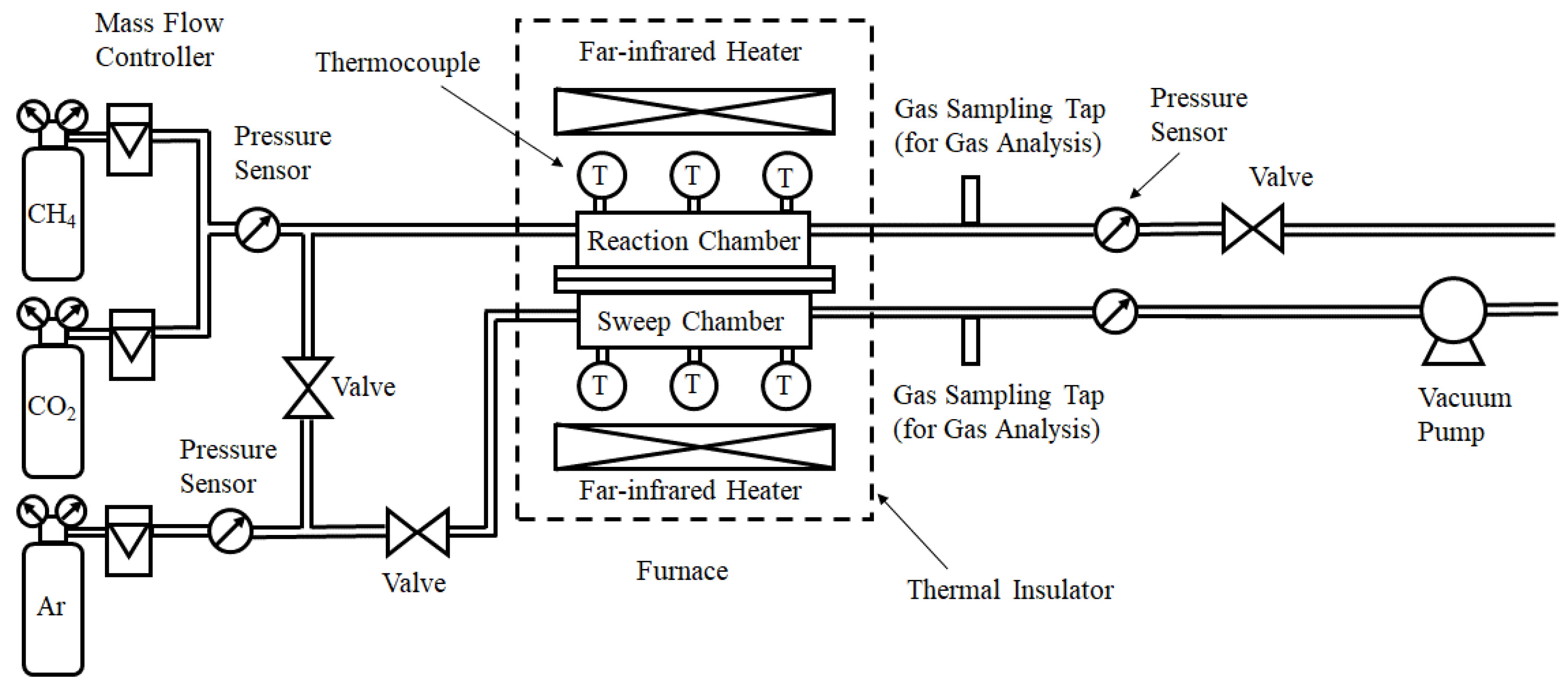
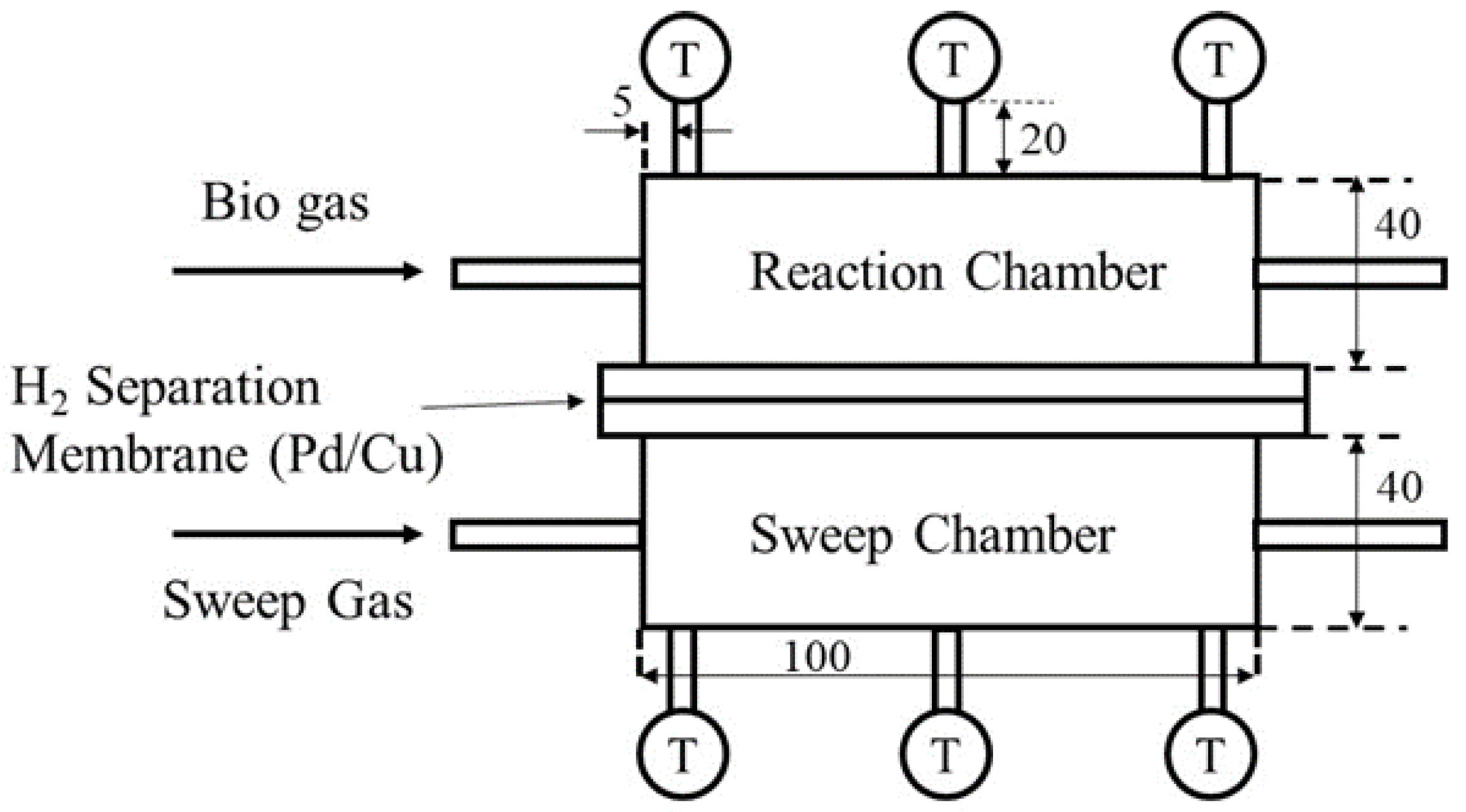
2.1. Experimental Apparatus Set-Up

Figure 1 illustrates the schematic drawing of the experimental set-up of this study. The experimental apparatus consists of a gas cylinder, mass flow controllers (S48–32; producer: HORIBA METRON INC.; Kyoto, Japan), pressure sensors (KM31; producer: NAGANO KEIKI; Tokyo, Japan), valves, a vacuum pump, a reactor composed of reaction chamber and sweep chamber, and gas sampling taps. The reactor is installed in an electric furnace. The temperature in the electric furnace is controlled by far-infrared heaters (MCHNNS1; producer: MISUMI; Tokyo, Japan). CH4 gas with a purity over 99.4 vol% and CO2 gas with a purity over 99.9 vol% are controlled by mass flow controllers and mixed before flowing into the reaction chamber. The pressure of the mixed gas at the inlet of the reaction chamber is measured using pressure sensors. Ar gas with a purity over 99.99 vol% is controlled using a mass flow controller, and the pressure of the Ar gas is measured using a pressure sensor. Ar is supplied as a sweep gas. The exhausted gas at the outlet of reaction chamber and sweep chamber is suctioned using a gas syringe via the gas sampling tap. The concentration of sampled gas is measured using a TCD gas chromatograph (Micro GC CP4900; producer: GL Science; Tokyo, Japan) and a methanizer (producer: GL Science; Tokyo, Japan). The minimum resolution of the TCD gas chromatograph as well as the methanizer is 1 ppmV. The gas pressure at the outlet of the reactor is measured using a pressure sensor. The gas concentration and pressure are measured at the outlet of reaction chamber and sweep chamber, respectively.
Figure 2 illustrates the detail of the reactor in this study. The reactor is composed of a reaction chamber, a sweep chamber and a H2 separation membrane. The reaction chamber and the sweep chamber are made of stainless steel with a size of 40 mm × 100 mm × 40 mm. The volume of the reaction space is 16 × 10−5 m3. A porous pure Ni catalyst or a Ni/Cr (Cr: 35 wt%) catalyst is charged in the reaction chamber. The mean hole diameters of the Ni catalyst and the Ni/Cr catalyst are 0.8 mm. According to the producer brochure, the porosities of a Ni and a Ni/Cr catalyst are 0.95 and 0.93, respectively. The weights of the charged Ni catalyst and Ni/Cr catalyst are 53.3 g and 70.3 g, respectively. Figure 3 shows a photo of the catalysts filled in the reactor of this study. A Pd/Cu alloy membrane (Cu of 40 wt%; producer: Tanaka Kikinzoku Kogyo; Tokyo, Japan) is installed between the reaction chamber and the sweep chamber, which helps to separate H2. The thickness of the Pd/Cu alloy membrane is 20 μm. This study considers that the key parameters to decide the performance of H2 separation membrane are thickness and composition, i.e., the weight ratio of Cu to Pd. When the thickness of the H2 separation membrane decreases, the performance of H2 separation is improved due to the decrease in permeation resistance. In addition, the performance of H2 separation is improved when the ratio of Cu to Pd decreases, resulting from the superior performance of H2 separation of Pd compared to that of Cu. In this study, the authors have used the commercial Pd/Cu membrane with the thickness of 20 μm. The producer of the Pd/Cu membrane is Tanaka Kikinzoku Kogyo, which is a very famous noble metal producer in Japan. According to the producer of the Pd/Cu membrane, the thinnest commercial Pd/Cu membrane is 20 μm due to the strength. We measure the temperatures at the inlet, the middle and the outlet of the reaction and sweep chambers using K-type thermocouples. We collect the measured temperatures and pressures using a data logger (GL240; producer: Graphtec Corporation; Yokohama, Japan).
Table 1 shows the experimental parameters in this study. The molar ratio of the supplied CH4:CO2 is varied to 1.5:1, 1:1 and 1:1.5. In this case, CH4:CO2 = 1.5:1 simulates a biogas. The feed ratio of sweep gas, which is defined as the flow rate of sweep gas divided by the flow rate of supply gas consisting of CH4 and CO2, has been set at 1.0 since the best performance of CH4 dry reforming was confirmed at this condition from the authors’ previous study [30]. The pressure difference between the reaction chamber and the sweep chamber, which is measured by the pressure sensors installed at the outlet of the reaction chamber and the outlet of sweep chamber is varied to 0 MPa, 0.010 MPa and 0.020 MPa. The impact of the molar ratio on the performance of CH4 dry reforming has been examined by changing the pre-set reaction temperature to 400 °C, 500 °C and 600 °C. The temperature of the reaction chamber and sweep chamber are measured using thermocouples as shown in Figure 1. In this study, the temperature means the initial temperature of reaction chamber and sweep chamber, i.e., the pre-heated temperature before supplying the mixed gas of CH4 and CO2, which are measured and confirmed by thermocouples. The gas concentrations in the reaction and sweep chambers have been evaluated using an FID gas chromatograph (producer: GL Science; Tokyo, Japan) and a methanizer (producer: GL Science; Tokyo, Japan). This study exhibits the mean data of five trials for each experimental condition in the following figures. The distribution of each gas concentration is below 10%.

2.2. Evaluation Factor for Performance of Proposed Reactor

We evaluate the performance of the proposed reactor by the gas concentration at the outlet of the reaction and sweep chambers, including CH4 conversion (XCH4), CO2 conversion (XCO2), H2 yield (YH2), H2 selectivity (SH2) and CO selectivity (Sco). This study defines them as follows:
XCH4 = {(CCH4, inCCH4, out)}/(CCH4, in) × 100
XCO2 = {(CCO2, inCCO2, out)}/(CCO2, in) × 100
YH2 = (1/2CH2, out)/(CCH4, in) × 100
SH2 = CH2, out/(CH2, out + CCO, out) × 100
SCO = CCO, out/(CH2, out + CCO, out) × 100
where CCH4, in is a concentration of CH4 at the inlet of reaction chamber (ppmV), CCH4, out is a concentration of CH4 at the outlet of reaction chamber (ppmV), CCO2, in is a concentration of CO2 at the inlet of reaction chamber (ppmV), CCO2, out is a concentration of CO2 at the outlet of reaction chamber (ppmV), CH2, out is a concentration of H2 at the outlet of reaction chamber and sweep chamber (ppmV), and CCO, out is a concentration of CO at the outlet of reaction chamber (ppmV).
Moreover, this study also evaluates H2 permeability (H) and permeation flux (F) as follows:
H = (CH2, out, sweep)}/{(CH2, out, sweep) + (CH2, out, react)} × 100
F = P ( P r e a c t , a v e P s w e e p , a v e ) δ × 100  
where CH2, out, sweep is a concentration of H2 at the outlet of sweep chamber (ppmV), CH2, out, react is a concentration of H2 at the outlet of reaction chamber (ppmV), P is a permeation factor (mol/(m·s·Pa0.5)), Preact, ave is an average pressure of the reaction chamber (MPa), Psweep, ave is an average pressure of sweep chamber (MPa), and δ is the thickness of the Pd/Cu alloy membrane (m).
Moreover, this study also evaluates the thermal efficiency of the proposed reactor (η). The definition of thermal efficiency of the proposed reactor is as follows:
η = Q H 2 ( W S . C . + W R . C . + W p ) × 100
where QH2 is the heating value of produced H2 based on a lower heating value (W), WR.C. is the amount of pre-heating of the supply gas for the reaction chamber (W), WS.C. is the amount of pre-heating of the sweep gas for the sweep chamber (W), and Wp is the pump power to provide the pressure difference between the reaction chamber and the sweep chamber (W).

3. Results and Discussion

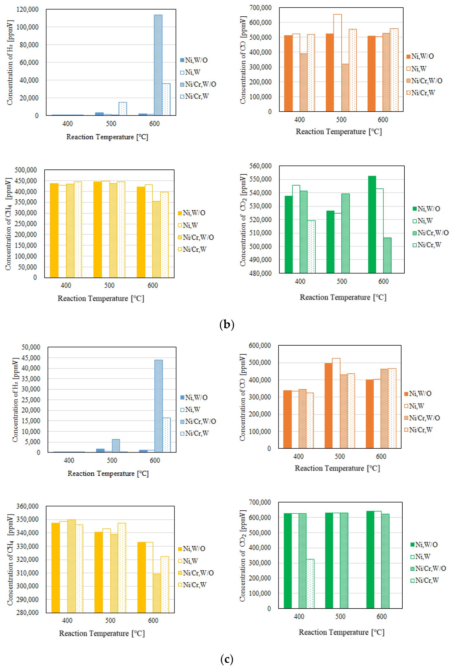
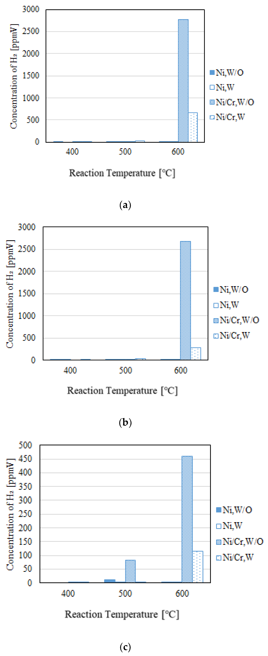
3.1. Impact of Pre-Set Reaction Temperature

Figure 4 exhibits the effect of the pre-set reaction temperature on each gas concentration in the reaction chamber varying the molar ratio of CH4/CO2. Figure 5 shows the impact of the pre-set reaction temperature on the concentration of H2 in the sweep chamber changing the molar ratio of CH4/CO2. In these figures, the pressure difference between the reaction chamber and the sweep chamber is 0.010 MPa. In addition, W and W/O indicates the condition with a sweep gas and that without a sweep gas in these figures, respectively. Table 2 lists CH4 conversion, CO2 conversion, H2 yield, H2 selectivity, CO selectivity, H2 permeability, permeation flux and thermal efficiency.
We can see from Figure 4 that the concentration of H2 and the ratio of concentration of H2 to that of CO increase with the increase in the pre-set reaction temperature regardless of the molar ratio of CH4/CO2. Since Equations (1) and (5) are endothermic reactions, the concentration of H2 and the ratio of concentration of H2 to that of CO increase with the increase in the pre-set reaction temperature [31,32]. Additionally, we can see from Figure 5 that the concentration of H2 in the sweep chamber increases with the increase in the pre-set reaction temperature regardless of the molar ratio of CH4/CO2. At higher pre-set reaction temperature, the concentration of H2 in the reaction chamber is higher compared to the lower pre-set reaction temperature. Since the difference of concentration of H2 between the reaction chamber and the sweep chamber is larger at the high pre-set reaction temperature such as 600 °C, the driving force for H2 separation increases. As a result, the concentration of H2 in the sweep chamber increases with the increase in the pre-set reaction temperature.
Comparing the concentration of H2 using a Ni catalyst with that using a Ni/Cr catalyst shown in Figure 4, the concentration of H2 using a Ni/Cr catalyst is larger especially at 600 °C. Although no study has previously investigated a Ni/Cr catalyst for biogas dry reforming, several Ni alloy catalysts have exhibited better performance compared with a pure Ni catalyst [5,6,7,8,9,10,11,12,13]. The composite catalysts of Ni alloy give synergistic interactions, which reduce the NiO species and the particle size, resulting in the enhancement of performance as well as resistance against a carbon formation [33,34].
According to Table 2, it is found that most of the CO2 conversion shows a negative value. According to not only the concentrations of H2, CH4 and CO2, indicated in Figure 4, but also CH4 and CO2 conversion, indicated in Table 2, the reaction consuming CH4 and producing CO2 occurs. Additionally, it is found from Table 2 that CO selectivity is much higher compared to H2 selectivity. In this study, it is thought that some H2 remained in the reaction chamber as shown in Figure 4, although some H2 moved to the sweep chamber as shown in Figure 5. In other words, all H2 produced by dry reforming does not move to the sweep chamber. Therefore, it can be explained as follows: (i) H2 is produced by the reactions shown in Equations (1) and (5); (ii) the produced H2 is consumed by the reaction shown in Equation (2), resulting in CO production; (iii) a part of CO produced the reaction shown in Equations (1) and (2) is consumed during the reaction shown in Equation (6); (iv) H2O produced during the reactions of Equations (2) and (3) are consumed by Equation (4). The methanizer and TCD gas chromatograph used in this study for the gas analysis cannot detect H2O. Therefore, the authors have inferred the reaction process to explain that CO2 conversion shows a negative value. The authors are currently investigating the reaction mechanism by the numerical simulation using a commercial software COMSOL Multiphysics. In this numerical simulation, Equations (2)–(4) as well as (1) are considered. As a result, the authors have confirmed the production of H2O. The authors would like to prove the reaction mechanism claimed in this paper in the near future work.
It is known from Table 2 that CO selectivity is much higher compared to H2 selectivity. According to the previous studies on biogas dry reforming using a Zr- and Y-modified Ni/Mg/Al double-layered hydroxide catalyst or a CeO2-MgO/Ni catalyst [35,36], the H2/CO ratio, i.e., H2 selectivity, increases with the pre-set reaction temperature from 600 °C to 850 °C or from 700 °C to 900 °C, respectively. This indicates that dry reforming is favored and that CH4 has higher conversion compared to CO2 at temperatures over 600 °C [36]. This study set the reaction temperature under 600 °C. Therefore, CO selectivity is much higher than H2 selectivity. In addition, according to the literature survey, the ratio of H2 to CO (=H2 selectivity; SH2 in this study) using a Ni-SiO2@SiO2 [6] was from 0.2 to 0.9 when changing the temperature from 500 °C to 700 °C. On the other hand, the ratio of H2 to CO using a Ni-Ru bimetallic catalyst integrated with MFI zeolite-loaded cerium zirconium oxide [5] was approximately 1.0 from 500 °C to 800 °C. However, the definition of H2 selectivity was the ratio of the flow rate of H2 at the outlet of the reactor to the flow rate of CO at the outlet of the reactor, which is different from the definition in our study. In this study, SH2 is defined by Equation (12). Since the denominator of H2 selectivity equation in this study is larger than that in the reference, the H2 selectivity, i.e., SH2, shows the smaller value. However, this study thinks it is important to define the ratio of produced H2 compared to the produced H2 and CO shown in Equation (2) since we can know the production ratio of H2 intuitively.
Since the H2 yield is low, the thermal efficiency, which is influenced by the amount of produced H2 as shown in Equation (16), is also low. To obtain a higher H2 yield and thermal efficiency, the experiment will be conducted at over 600 °C in future work.
This study also defines the other H2 selectivity, CO selectivity and carbon balance as follows:
SH2 = CH2, out/(2·CCH4, out) × 100
SCO = CCO, out/(CCH4, out + CCO2, out) × 100
Carbon Balance = (CCH4, unreacted + CCO2, unreacted + CCO, out)/(CCH4, in + CCO2, in) × 100
where CCH4, unreacted is an unreacted concentration of CH4 at the outlet of the reaction chamber (ppmV), and CCO2, unreacted is an unreacted concentration of CO2 at the outlet of the reaction chamber (ppmV). After the calculation of H2 selectivity, CO selectivity and carbon balance, it is revealed that the highest SH2 is obtained in the case of CH4:CO2 = 1.5:1 using a Ni/Cr catalyst at 600 °C without a sweep gas, which is 26.5%. The condition using a Ni/Cr catalyst at 600 °C without a sweep gas provides the highest SH2 compared to the other conditions irrespective of molar ratio. In addition, it is revealed that the highest Sco is obtained in the case of CH4:CO2 = 1:1.5 using the Ni/Cr catalyst at 600 °C with a sweep gas, which is 373%. The condition using the Ni/Cr catalyst at 600 °C with a sweep gas provides the highest Sco compared to the other conditions irrespective of molar ratio. Regarding the carbon balance, it is revealed that the highest carbon balance is obtained in the case of CH4:CO2 = 1.5:1 using the Ni/Cr catalyst at 600 °C with a sweep gas, which is 144%. The condition using the Ni/Cr catalyst at 600 °C with a sweep gas provides the highest carbon balance compared to the other conditions irrespective of molar ratio.

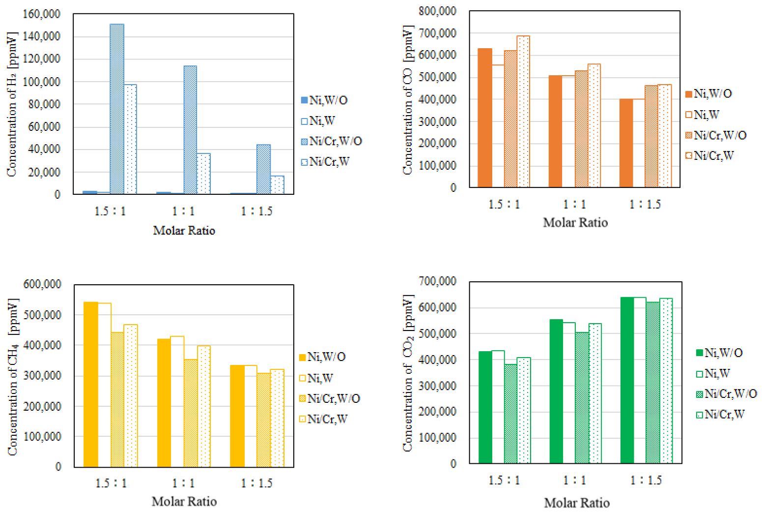
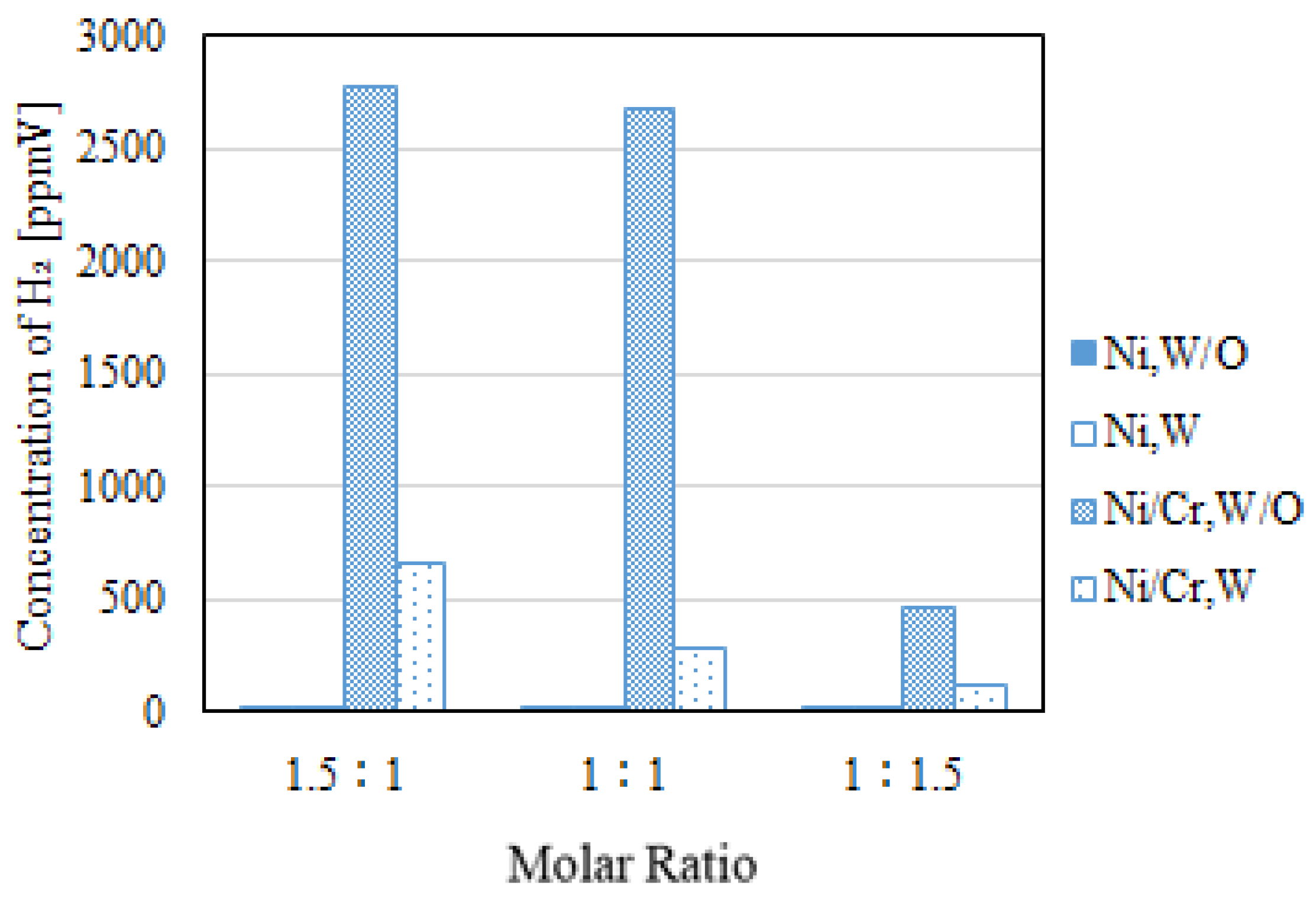
3.2. Impact of Molar Ratio of CH4/CO2

Figure 6 shows the impact of the molar ratio of CH4/CO2 on each gas concentration in the reaction chamber. Figure 7 shows the impact of the molar ratio of CH4/CO2 on the concentration of H2 in the sweep chamber. In these figures, the pressure difference between the reaction chamber and the sweep chamber is 0.010 MPa, and the reaction temperature is 600 °C. Additionally, W and W/O indicate the condition with a sweep gas and without a sweep gas in these figures, respectively.
We can see from Figure 6 that the highest concentration of H2 is obtained for the molar ratio of CH4:CO2 = 1.5:1 at 600 °C using the Ni/Cr catalyst. This study claims that some H2 remained in the reaction chamber as shown in Figure 4, although some H2 moved to the sweep chamber, as shown in Figure 5. In other words, all H2 produced by dry reforming does not move to the sweep chamber. Since the amount of CH4 is larger in this case, it can be explained as follows: (i) H2 is produced by the reactions shown in Equations (1) and (5); (ii) the produced H2 is consumed by the reaction shown in Equation (2), resulting in CO production; (iii) a part of CO produced by reactions shown in Equations (1) and (2) is consumed by Equation (6); (iv) H2O produced by the reactions shown in Equations (2) and (3) are consumed during Equation (4).
We can see from Figure 7 that the concentration of H2 in the sweep chamber is higher, which follows the concentration of H2 in the reaction chamber. Since the difference of the concentration of H2 between the reaction chamber and the sweep chamber is larger, the driving force for H2 separation increases. As a result, the concentration of H2 in the sweep chamber increases.
Comparing the concentration of H2 using a Ni catalyst with that using a Ni/Cr catalyst, as exhibited in Figure 6, the concentration of H2 using a Ni/Cr catalyst is larger regardless of the molar ratio of CH4/CO2. Although no study has investigated a Ni/Cr catalyst for biogas dry reforming, several Ni alloy catalysts have exhibit better performance compared with a pure Ni catalyst [5,6,7,8,9,10,11,12,13]. The composite catalysts of Ni alloys give synergistic interactions, which reduce the NiO species and the particle size, resulting in the enhancement of performance as well as resistance against a carbon formation [33,34].

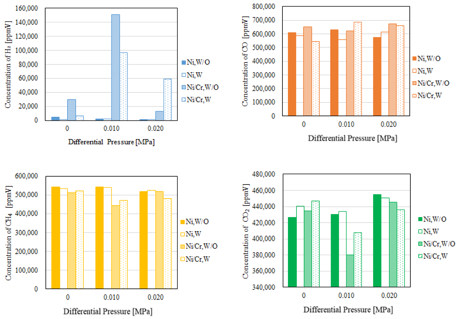
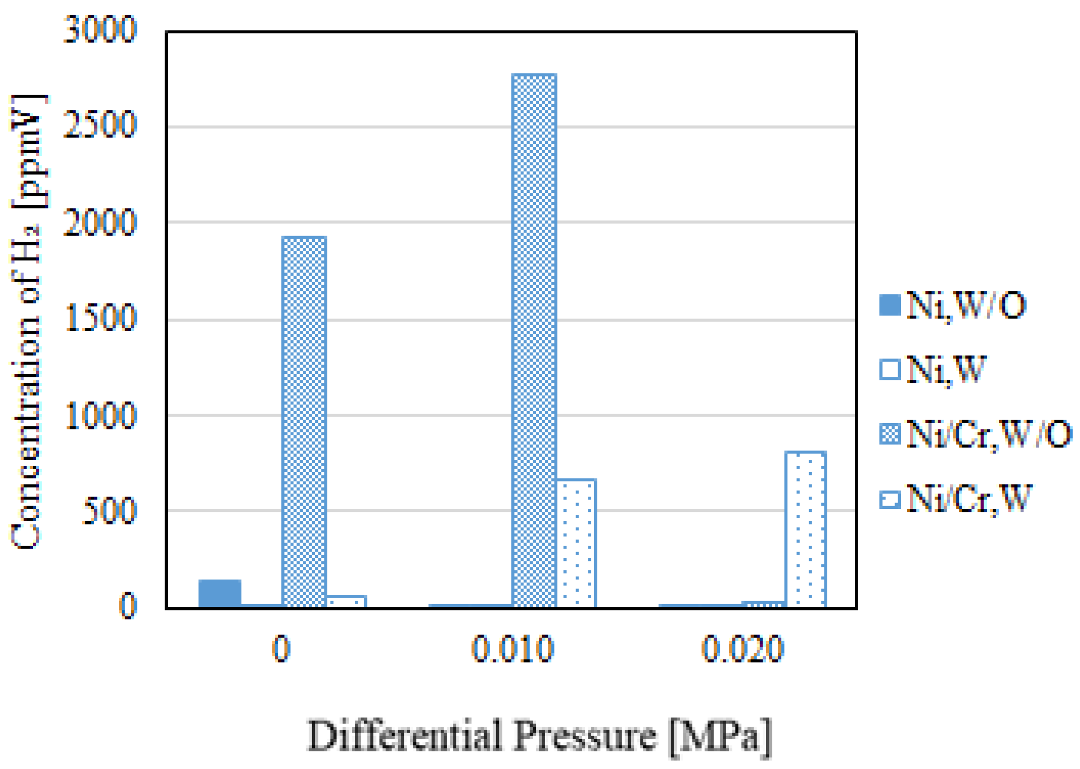
3.3. Impact of Differential Pressure

Figure 8 displays the effect of differential pressure on each gas concentration in the reaction chamber. Figure 9 exhibits the effect of differential pressure on concentration of H2 in the sweep chamber. The molar ratio of CH4/CO2 is 1.5:1, and the reaction temperature is 600 °C in these figures. In addition, W and W/O indicates the condition with a sweep gas and without a sweep gas in these figures, respectively.
Comparing the concentration of H2 using a Ni catalyst with that using a Ni/Cr catalyst indicated in Figure 8, the concentration of H2 using a Ni/Cr catalyst is larger irrespective of differential pressure. Although no study has investigated a Ni/Cr catalyst for biogas dry reforming, several Ni alloy catalysts have exhibited better performance compared with a pure Ni catalyst [5,6,7,8,9,10,11,12,13]. The composite catalysts of Ni alloys give synergistic interactions, which reduce the NiO species and the particle size, resulting in the enhancement of performance as well as resistance against a carbon formation [35,36]. In addition, according to a previous study reporting the performance of Ni/MgO with Sn, Ce, Mn and Co [16], the higher catalytic activity for Co-promoted catalysts can be attributed to its high affinity for O2 species due to promoting coke resistance properties. Another previous study reports that the performance of Ni/γ-Al2O3 [17] helps to promote catalytic activity and prevent carbon deposition. Therefore, the authors think that a Ni/Cr catalyst may more adequately prevent carbon deposition compared to a Ni catalyst and that the overall performance of a Ni/Cr catalyst is better than that of a Ni catalyst.
In addition, the concentrations of H2 using a Ni/Cr catalyst in the reaction chamber and the sweep chamber without a sweep gas are higher than those with a sweep gas at the differential pressure of 0.010 MPa, as shown in Figure 8 and Figure 9. With a sweep gas, the kinetic pressure in the sweep chamber is larger, resulting in a decrease in the static pressure in the sweep chamber. It is thought that the difference of static pressure between the reaction chamber and the sweep chamber is larger, resulting in the performance of the H2 separation membrane being improved. It is necessary to match the H2 separation rate of the H2 separation membrane with the H2 production rate of the catalyst in order to obtain higher H2 production performance. Since the H2 separation rate with a sweep gas is too fast, the performance of H2 production with a sweep gas is lower compared to that without a sweep gas. On the other hand, the concentrations of H2 using a Ni/Cr catalyst in the reaction chamber and the sweep chamber with a sweep gas are higher than those without a sweep gas at the differential pressure of 0.020 MPa, as shown in Figure 8 and Figure 9. Since the amount of produced H2 in the reaction chamber in the case of the differential pressure of 0.020 MPa is lower compared to the case of the differential pressure of 0.010 MPa, it is easy to separate H2 using a sweep gas. Considering H2 separation only, the H2 separation performance of the Pd-based membrane is promoted with the increase in the pressure difference between the reaction chamber and the sweep chamber [37]. Additionally, the H2 separation performance of the Pd-based membrane is better when the purity of H2 is higher [38]. According to Figure 8, it is seen that the highest concentration of H2 in the reaction chamber is achieved at the differential pressure of 0.010 MPa when using a Ni/Cr catalyst. The concentration of H2 in the reaction chamber is higher, i.e., the purity of H2 is higher, at the differential pressure of 0.010 MPa due to the higher performance of the Ni/Cr catalyst. As a result, the concentration of H2 in the sweep chamber is also higher because of better H2 separation performance.

4. Discussion

From the investigation of this study, the highest concentration of H2 is obtained using a Ni/Cr catalyst when the molar ratio of CH4:CO2 is 1.5:1 at the differential pressure of 0.010 MPa and the reaction temperature of 600 °C without a sweep gas. Under this condition, the H2 yield and H2 selectivity are 12.8% and 17.5%, respectively. In addition, the thermal efficiency is 174%. As for the stability, the total test time of each catalyst in this study was approximately 50 h. After finishing all experiments, the catalyst has kept the performance and apparent form. When using a Ni catalyst, the coke formation (carbon deposition) was observed after the experiments. Figure 10 shows the photo indicating the carbon deposition using a Ni catalyst after the experiments. To improve the performance of H2 production and thermal efficiency, the following subjects are considered: (i) the optimization of shape, i.e., the pore size and weight ratio of the Ni/Cr catalyst, which decides the performance of dry reforming; (ii) the optimization of the thickness and weight ratio of the Pd/Cu membrane, which decides the H2 separation performance; (iii) the matching of the H2 separation rate of the Pd/Cu membrane and the H2 production rate of the catalyst, which decides the optimum experimental condition. These are the future works that will follow this study.

5. Conclusions

This study has investigated the performance characteristics of biogas dry reforming conducted in a membrane reactor using a Ni/Cr catalyst and compared these characteristics with those obtained using a Ni catalyst. The effect of the pre-set reaction temperature, the molar ratio of CH4:CO2 and the pressure gap between the reaction chamber and the sweep chamber on the characteristics of biogas dry reforming is also investigated. As a result, the following conclusions are obtained:
(i)
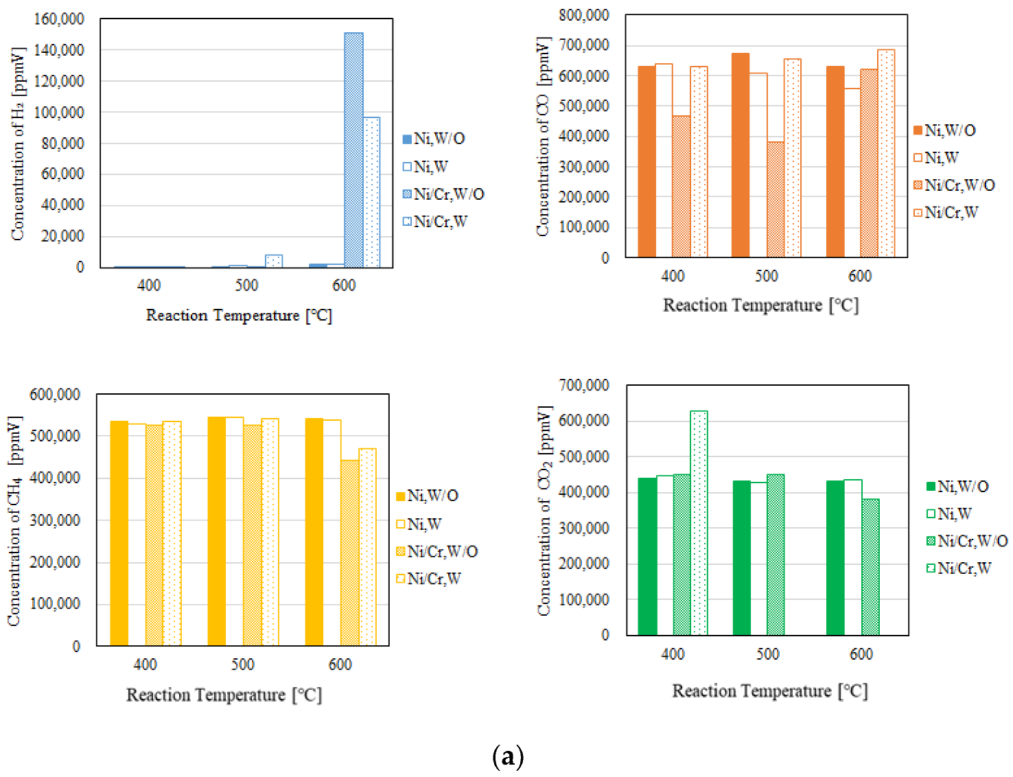
The concentration of H2 as well as the ratio of concentration of H2 to that of CO increase with the increase in the pre-set reaction temperature in the reaction chamber irrespective of the molar ratio of CH4/CO2. The concentration of H2 in the sweep chamber also increases with the increase in the pre-set reaction temperature.
(ii)
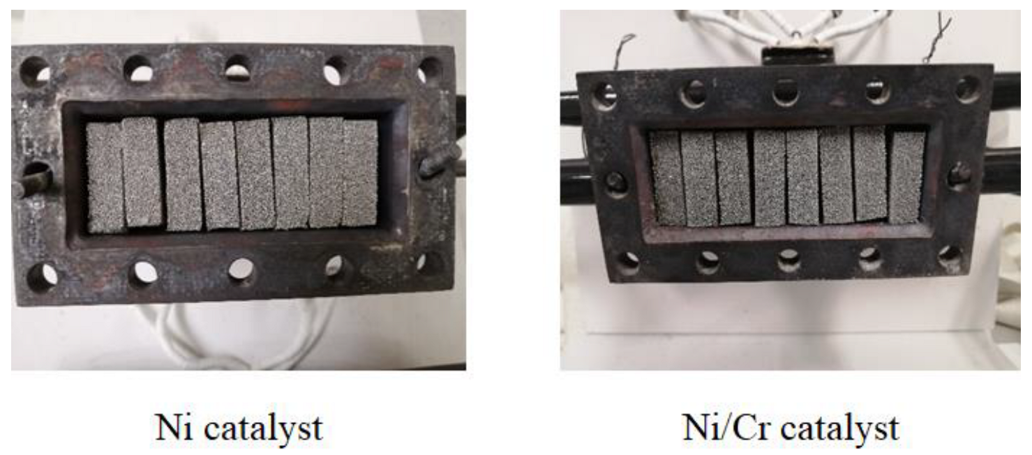
The concentration of H2 using a Ni/Cr catalyst is larger compared to that using a Ni catalyst regardless of the pre-set reaction temperature, the molar ratio of CH4/CO2 and the differential pressure.
(iii)
The highest concentrations of H2 in the reaction chamber and the sweep chamber are obtained when the molar ratio of CH4:CO2 is 1.5:1 using a Ni/Cr catalyst among the investigated molar ratio conditions.
(iv)
The concentrations of H2 using a Ni/Cr catalyst in the reaction chamber and the sweep chamber without a sweep gas are higher than those with a sweep gas at the differential pressure of 0.010 MPa, while the concentrations of H2 using a Ni/Cr catalyst in the reaction chamber and the sweep chamber with a sweep gas are higher than those without a sweep gas at the differential pressure of 0.020 MPa.
(v)
The highest concentration of H2 is obtained using a Ni/Cr catalyst when the molar ratio of CH4:CO2 is 1.5:1 at the differential pressure of 0.010 MPa and the pre-set reaction temperature of 600 °C without a sweep gas. Under this condition, H2 yield, H2 selectivity and thermal efficiency are 12.8%, 17.5% and 174%, respectively.

Author Contributions

Conceptualization and writing—original draft preparation, A.N.; experiment data curation, Y.H. and S.I.; writing—review and editing, M.L.K.; All authors have read and agreed to the published version of the manuscript.

Funding

The preset research was funded by the Iwatani Naoji Foundation and the joint research program of the Institute of Materials and Systems for Sustainability, Nagoya University.

Data Availability Statement

The authors agree to share the data of the article published in this journal.

Acknowledgments

The authors acknowledge the financial support from the Iwatani Naoji Foundation and the joint research program of the Institute of Materials and Systems for Sustainability, Nagoya University.

Conflicts of Interest

The authors declare no conflict of interest.

References

  1. Global Monitoring Laboratory. Available online: https://gml.noaa.gov/ccgg/trends/global.html (accessed on 15 December 2022).
  2. Kalai, D.Y.; Stangeland, K.; Jin, Y.; Tucho, W.M.; Yu, Z. Biogas dry reforming for syngas production on La promoted hydrotalcite-derived Ni catalyst. Int. J. Hydrog. Energy 2018, 43, 19438–19450. [Google Scholar] [CrossRef]
  3. World Bioenergy Association. Global Bioenergy Statistics. Available online: https://worldbioenergy.org./global-bioenergy-statistics (accessed on 15 December 2022).
  4. The Japan Gas Association. Available online: https://www.gas.or.jp/gas-life/biomass/ (accessed on 20 March 2023).
  5. Mao, C.; Chen, S.; Shang, K.; Liang, L.; Ouyang, J. Highly active Ni-Ru bimetallic catalyst integrated with MFI zeolite loaded Cerium Zirconium Oxide for dry reforming of methane. ACS Appl. Mater. Interfaces 2022, 14, 47616–47632. [Google Scholar] [CrossRef] [PubMed]
  6. Kaviani, M.; Rezaei, M.; Alavi, S.M.; Akbari, E. High coke resistance Ni-SiO2@SiO2 core-shell catalyst for biogas dry reforming: Effects of Ni loading and calcination temperature. Fuel 2022, 330, 125609. [Google Scholar] [CrossRef]
  7. Ha, Q.L.M.; Atia, H.; Kreyenschlte, C.; Lund, H.; Bartling, S.; Lisak, G.; Wohlrab, S.; Armbruster, U. Effects of modifier (Gd, Sc, La) addition on the stability of low Ni content catalyst for dry reforming of model biogas. Fuel 2022, 312, 122823. [Google Scholar] [CrossRef]
  8. Calgaro, C.O.; Lima, D.S.; Tonietto, R.; Perez-Lopez, O.W. Biogas dry reforming over Ni-Mg-La-Al catalysts: Influence of La/Mg ratio. Catal. Lett. 2021, 15, 267–280. [Google Scholar] [CrossRef]
  9. Moreno, A.A.; Ramirez-Reina, T.; Ivanova, S.; Roger, A.C.; Centeno, M.A.; Odriozola, J.A. Bimetallic Ni-Ru and Ni-Re catalysts for dry reforming of methane: Understanding the synergies of the selected promoters. Front. Chem. 2021, 9, 694976. [Google Scholar] [CrossRef]
  10. Fakeeha, A.H.; Fatesh, A.S.A.; Ibrahim, A.A.; Kurdi, A.N.; Abasaeed, A.E. Yttria modified ZrO2 supported Ni catalysts for CO2 reforming of methane: The role of Ce promoter. ACS Omega 2021, 6, 1280–1288. [Google Scholar] [CrossRef]
  11. Shah, M.; Mondal, P. Optimization of CO2 reforming of methane process for the syngas production over Ni/Ce/TiO2-ZrO2 catalyst using the Taguchi method. Int. J. Hydrog. Energy 2021, 46, 22799–22812. [Google Scholar] [CrossRef]
  12. Rosset, M.; Feris, L.A.; Perez-Lopez, O.W. Biogas dry reforming using Ni-Al-LDH catalysts reconstructed with Mg and Zn. Int. J. Hydrog. Energy 2021, 46, 20359–20376. [Google Scholar] [CrossRef]
  13. Sache, E.; Moreno, A.A.; Reina, T.R. Biogas conversion to syngas using advanced Ni-promoted pyrochlore catalysts: Effect of the CH4/CO2 ratio. Front. Chem. 2021, 9, 672419. [Google Scholar] [CrossRef]
  14. Chava, R.; Purbia, D.; Roy, B.; Janardhanan, V.M.; Bahurudeen, A.; Appari, S. Effect of calcination time on the catalyst activity of Ni/γ-Al2O3 cordierite monolith for dry reforming of biogas. Int. J. Hydrog. Energy 2021, 46, 6341–6357. [Google Scholar] [CrossRef]
  15. Sharma, H.; Dhir, A. Hydrogen augmentation of biogas through dry reforming over bimetallic nickel-cobalt catalysts supported on titania. Fuel 2020, 279, 118389. [Google Scholar] [CrossRef]
  16. Usman, M.; Daud, W.M.A.W.; Abbas, F. Dry reforming of methane: Influence of process parameters—A review. Renew. Sustain. Energy Rev. 2015, 45, 710–744. [Google Scholar] [CrossRef] [Green Version]
  17. Charisiou, N.D.; Douvartzides, S.L.; Siakavelas, G.I.; Tzounis, L.; Sebastian, V.; Stolojan, V.; Hinder, S.J.; Baker, M.A.; Polychronopoulou, K.; Goula, M.A. The relationship between reaction temperature and carbon deposition on nickel catalysts based on Al2O3, ZrO2 or SiO2 supports during the biogas dry reforming reaction. Catalysts 2019, 9, 676. [Google Scholar] [CrossRef] [Green Version]
  18. Bosko, M.L.; Munera, J.F.; Lombardo, E.A.; Cornaglia, L.M. Dry reforming of methane in membrane reactors using Pd and Pd-Ag composite membranes on a NaA zeolite modified porous stainless steel support. J. Membr. Sci. 2010, 364, 17–26. [Google Scholar] [CrossRef]
  19. Munera, J.; Faroldi, B.; Fruits, E.; Lombardo, E.; Cornaglia, L.; Carrazan, S.G. Supported Rh nanoparticles on CaO-SiO2 binary systems for the reforming of methane by carbon dioxide in membrane reactors. Appl. Catal. A Gen. 2014, 474, 114–124. [Google Scholar] [CrossRef]
  20. Simakov, D.S.A.; Roman-Leshkov, Y. Highly efficient methane reforming over a low-loading Ru/-Al2O3 catalyst in a Pd-Ag membrane reactor. AICHE J. 2018, 64, 3101–3108. [Google Scholar] [CrossRef]
  21. Liu, J.; Bellini, S.; Nooijer, N.C.A.; Sun, Y.; Tanaka, D.A.P.; Tang, C.; Li, H.; Gallucci, F.; Caravella, A. Hydrogen permeation and stability in ultra-thin Pd-Ru supported membrane. Int. J. Hydrog. Energy 2020, 45, 7455–7467. [Google Scholar] [CrossRef]
  22. Fontana, A.D.; Faroldi, B.; Cornaglia, L.M.; Tarditi, A.M. Development of catalytic membranes over PdAu selective films for hydrogen production through the dry reforming of methane. Mol. Catal. 2020, 481, 100643. [Google Scholar] [CrossRef]
  23. Jia, H.; Xu, H.; Sheng, X.; Yang, X.; Shen, W.; Goldbach, A. High-temperature ethanol steam reforming in PdCu membrane reactor. J. Membr. Sci. 2020, 605, 118083. [Google Scholar] [CrossRef]
  24. Roa, F.; Way, D. Influence of alloy composition and membrane fabrication on the pressure dependence of the hydrogen flux of palladium-copper membranes. Ind. Eng. Chem. Res. 2003, 42, 5827–5835. [Google Scholar] [CrossRef]
  25. Garcia-Garcia, F.R.; Soria, M.A.; Mateos-Pedero, C.; Guerrero-Ruiz, A.; Odriguez-Ramos, I.; Li, K. Dry reforming of methane using Pd-based membrane reactors fabricated from different substrates. J. Membr. Sci. 2013, 435, 218–225. [Google Scholar] [CrossRef]
  26. Ugarte, P.; Duran, P.; Lasobras, J.; Soler, J.; Menendez, M.; Herguido, J. Dry reforming of biogas in fluidized bed; process intensification. Int. J. Hydrog. Energy 2017, 42, 13589–13597. [Google Scholar] [CrossRef] [Green Version]
  27. Kumar, S.; Kumar, B.; Kumar, S.; Jilani, S. Comparative modeling study of catalytic membrane reactor configurations for syngas production by CO2 reforming of methane. J. CO2 Util. 2017, 20, 336–346. [Google Scholar] [CrossRef]
  28. Leimert, J.M.; Karl, J.; Dillig, M. Dry reforming of methane using a nickel membrane reactor. Processes 2017, 5, 82. [Google Scholar] [CrossRef] [Green Version]
  29. Li, H.; Goldbach, A.; Li, W.; Xu, H. PdC formation in ultra-thin Pd membrane during separation of H2/CO mixtures. Int. J. Hydrog. Energy 2016, 41, 10193–10201. [Google Scholar] [CrossRef]
  30. Nishimura, A.; Ohata, S.; Okukura, K.; Hu, E. The Impact of Operating Conditions on the Performance of a CH4 Dry Reforming Membrane Reactor for H2 Production. J. Energy Power Technol. 2020, 2, 8. [Google Scholar] [CrossRef]
  31. Rosha, P.; Mohapatra, S.K.; Mahla, S.K.; Dhir, A. Hydrogen Enrichment of Biogas via Dry and Autothermal-dry Reforming with Pure Nickel (Ni) Nanoparticle. Energy 2019, 172, 733–739. [Google Scholar] [CrossRef]
  32. Sache, E.; Johnson, S.; Pastor-Perez, S.; Horri, B.A.; Reina, T.R. Biogas Upgrading via Dry Reforming over a Ni-Sn/CeO2-Al2O3 Catalyst: Influence of the Biogas Source. Energies 2019, 12, 1007. [Google Scholar] [CrossRef] [Green Version]
  33. Wu, H.; Pantatloera, G.; Parolaa, V.L.; Venezia, A.M.; Collard, X.; Aprile, C.; Liotta, L.F. Bi- and trimetallic Ni catalysts over Al2O3 and Al2O3-MOx (M = Ce or Mg) oxidized for methane dry reforming: Au and Pt additive effects. Appl. Catal. B Environ. 2014, 156–157, 350–361. [Google Scholar] [CrossRef]
  34. Yusuf, M.; Farooqi, A.S.; Keong, L.K.; Hellgardt, K.; Abdullah, B. Contemporary trends in composite Ni-based catalysts for CO2 reforming of methane. Chem. Eng. Sci. 2021, 229, 116072. [Google Scholar] [CrossRef]
  35. Swirk, K.; Galvez, M.E.; Motak, M.; Grzybek, T.; Ronning, M.; Costa, P.D. Dry reforming of methane over Zr- and Y-modified Ni/Mg/Al double-layered hydroxides. Catal. Commun. 2018, 117, 26–32. [Google Scholar]
  36. Al-Swai, B.M.; Osman, N.; Alnarabiji, M.S.; Adesina, A.A.; Abdulah, B. Syngas production via methane dry reforming over Ceria-Magnesite mixed odide-supported Nickel catalysts. Indust. Eng. Chem. Res. 2019, 58, 539–552. [Google Scholar] [CrossRef]
  37. Abdi, H.; Pourmahmound, N.; Soltan, J. A novel CFD simulation of H2 separation by Pd-based helical and straight membrane tubes. Korean J. Chem. Eng. 2020, 37, 2041–2053. [Google Scholar] [CrossRef]
  38. Sanz-Villanueva, D.; Alique, D.; Vizcaino, A.J.; Sanz, R.; Calles, J.A. Pre-activation of SBA-15 intermediate barriers with Pd nuclei to increase thermal and mechanical resistances of pore-plated Pd-membranes. Int. J. Hydrog. Energy 2021, 46, 20198–20212. [Google Scholar] [CrossRef]
Figure 1. Schematic drawing of experimental apparatus set-up.
Fuels 04 00019 g001
Figure 2. Schematic drawing of detail of the reactor.
Fuels 04 00019 g002
Figure 3. Photo for catalyst charged in the reactor.
Fuels 04 00019 g003
Figure 4. Impact of pre-set reaction temperature on each gas concentration in the reaction chamber (pressure difference: 0.010 MPa; (a) CH4:CO2 = 1.5:1; (b) CH4:CO2 = 1:1; (c) CH4:CO2 = 1:1.5).
Fuels 04 00019 g004aFuels 04 00019 g004b
Figure 5. Impact of pre-set reaction temperature on concentration of H2 in the sweep chamber (pressure difference: 0.010 MPa; (a) CH4:CO2 = 1.5:1; (b) CH4:CO2 = 1:1; (c) CH4:CO2 = 1:1.5).
Fuels 04 00019 g005
Figure 6. Impact of molar ratio of CH4/CO2 on each gas concentration in the reaction chamber (pressure difference: 0.010 MPa; pre-set reaction temperature: 600 °C).
Fuels 04 00019 g006
Figure 7. Impact of molar ratio of CH4/CO2 on concentration of H2 in the sweep chamber (pressure difference: 0.010 MPa; pre-set reaction temperature: 600 °C).
Fuels 04 00019 g007
Figure 8. Impact of differential pressure on each gas concentration in the reaction chamber (molar ratio of CH4/CO2 = 1.5:1; pre-set reaction temperature: 600 °C).
Fuels 04 00019 g008
Figure 9. Impact of differential pressure on concentration of H2 in the sweep chamber (molar ratio of CH4/CO2 = 1.5:1; pre-set reaction temperature: 600 °C).
Fuels 04 00019 g009
Figure 10. Carbon deposition when using a Ni catalyst.
Fuels 04 00019 g010
Table 1. Experimental parameters.
Pre-set reaction temperature (°C)400, 500, and 600
Pressure of supply gas (MPa)0.10
Pressure difference between the reaction chamber and the sweep chamber (MPa)0, 0.010, and 0.020
Molar ratio of supplied CH4:CO2
(Flow rate of CH4 and CO2 (NL/min))
1.5:1, 1:1, and 1:1.5
(1.088:0.725, 0.725:0.725, and 0.725:1.088)
Feed ratio of sweep gas to supply gas (-)0 and 1.0
Table 2. Comparison of CH4 conversion, CO2 conversion, H2 yield, H2 selectivity, CO selectivity, H2 permeability, permeation flux and thermal efficiency (pressure difference: 0.010 MPa; (a) CH4:CO2 = 1.5:1; (b) CH4:CO2 = 1:1; (c) CH4:CO2 = 1:1.5).
(a)
Pre-Set
Reaction
Temperature (°C)
CatalystSweep GasCH4
Conversion (%)
CO2
Conversion (%)
H2 Yield (%)H2 Selectivity (%)CO Selectivity (%)H2
Permeability (%)
Permeation Flux (mol/(m2·s))Thermal
Efficiency (%)
400NiW/O10.8−9.867.35 × 10−31.39 × 10−21001.155.00 × 10−50.154
W11.7−11.34.24 × 10−47.98 × 10−410005.00 × 10−55.72 × 10⁻²
Ni/CrW/O12.2−12.02.49 × 10−46.10 × 10−410050.25.00 × 10−53.51 × 10⁻³
W10.6−9.703.36 × 10−46.16 × 10−410098.35.00 × 10−52.29 × 10⁻³
500NiW/O9.25−7.455.94 × 10−20.10599.90.1412.50 × 10−50.991
W9.11−7.100.1050.20599.87.97 × 10−22.50 × 10−51.11
Ni/CrW/O12.6−1.263.19 × 10−38.39 × 10−31002.682.50 × 10−55.20 × 10⁻²
W9.66−6.220.6741.1798.80.2602.50 × 10−57.16
600NiW/O9.62−7.590.1990.37499.68.40 × 10−25.00 × 10−62.74
W10.1−8.490.1450.31299.60.1735.00 × 10−61.28
Ni/CrW/O26.14.9212.817.582.51.845.00 × 10−6174
W21.6−19.28.1512.088.00.6775.00 × 10−671.3
(b)
400NiW/O12.5−7.524.34 × 10−48.40 × 10−410029.95.00 × 10−55.89 × 10⁻³
W14.1−9.146.99 × 10−41.33 × 10−310040.15.00 × 10−55.61 × 10⁻³
Ni/CrW/O13.3−8.271.00 × 10−42.42 × 10−410005.00 × 10−51.76 × 10⁻³
W11.1−6.074.49 × 10−48.31 × 10−410080.35.00 × 10−52.80 × 10⁻³
500NiW/O11.0−5.290.3470.65699.32.88 × 10−22.50 × 10−54.82
W10.3−4.950.1620.24899.86.16 × 10−22.50 × 10−51.44
Ni/CrW/O12.8−7.833.67 × 10−39.80 × 10−31005.762.50 × 10−54.82 × 10⁻²
W10.8−2.821.492.5297.50.2692.50 × 10−513.2
600NiW/O15.9−10.50.2000.38899.31.065.00 × 10−62.27
W13.9−8.610.1350.26699.70.3715.00 × 10−60.987
Ni/CrW/O29.1−1.3111.71.6084.02.345.00 × 10−61.31
W20.4−8.093.675.7094.30.7715.00 × 10−626.7
(c)
400NiW/O13.1−4.591.04 × 10−32.45 × 10−310005.00 × 10−51.46 × 10⁻²
W12.9−4.417.04 × 10−41.66 × 10−310005.00 × 10−56.31 × 10⁻³
Ni/CrW/O12.6−4.215.04 × 10−41.09 × 10−31002925.00 × 10−51.80 × 10⁻³
W13.5−4.813.77 × 10−48.91 × 10−41001965.00 × 10−51.14 × 10⁻³
500NiW/O14.8−5.410.2200.35299.60.6282.50 × 10−52.43
W14.2−5.217.55 × 10−20.11599.90.1662.50 × 10−50.534
Ni/CrW/O15.3−5.010.7831.2298.81.342.50 × 10−68.58
W13.1−4.609.40 × 10−41.65 × 10−310036.22.50 × 10−54.89 × 10⁻³
600NiW/O16.8−6.840.1390.27599.70.2705.00 × 10−61.27
W16.8−6.850.1360.26999.70.2775.00 × 10−60.793
Ni/CrW/O22.7−3.655.537.9492.11.055.00 × 10−650.1
W19.4−6.052.073.1796.80.6925.00 × 10−612.0
Disclaimer/Publisher’s Note: The statements, opinions and data contained in all publications are solely those of the individual author(s) and contributor(s) and not of MDPI and/or the editor(s). MDPI and/or the editor(s) disclaim responsibility for any injury to people or property resulting from any ideas, methods, instructions or products referred to in the content.

