
The Addition of Particles to an Alternative Jet Fuel


Abstract
:1. Introduction
2. Materials and Methods
2.1. Fuels Preparation and Properties
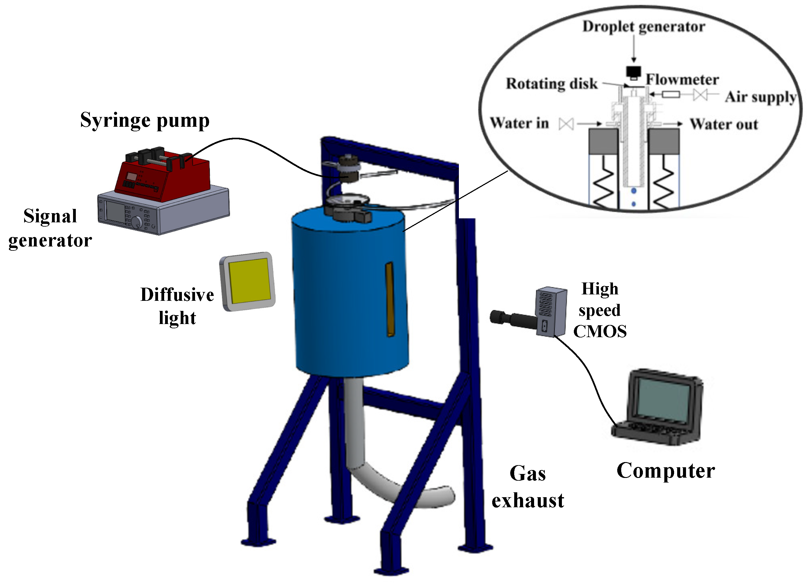
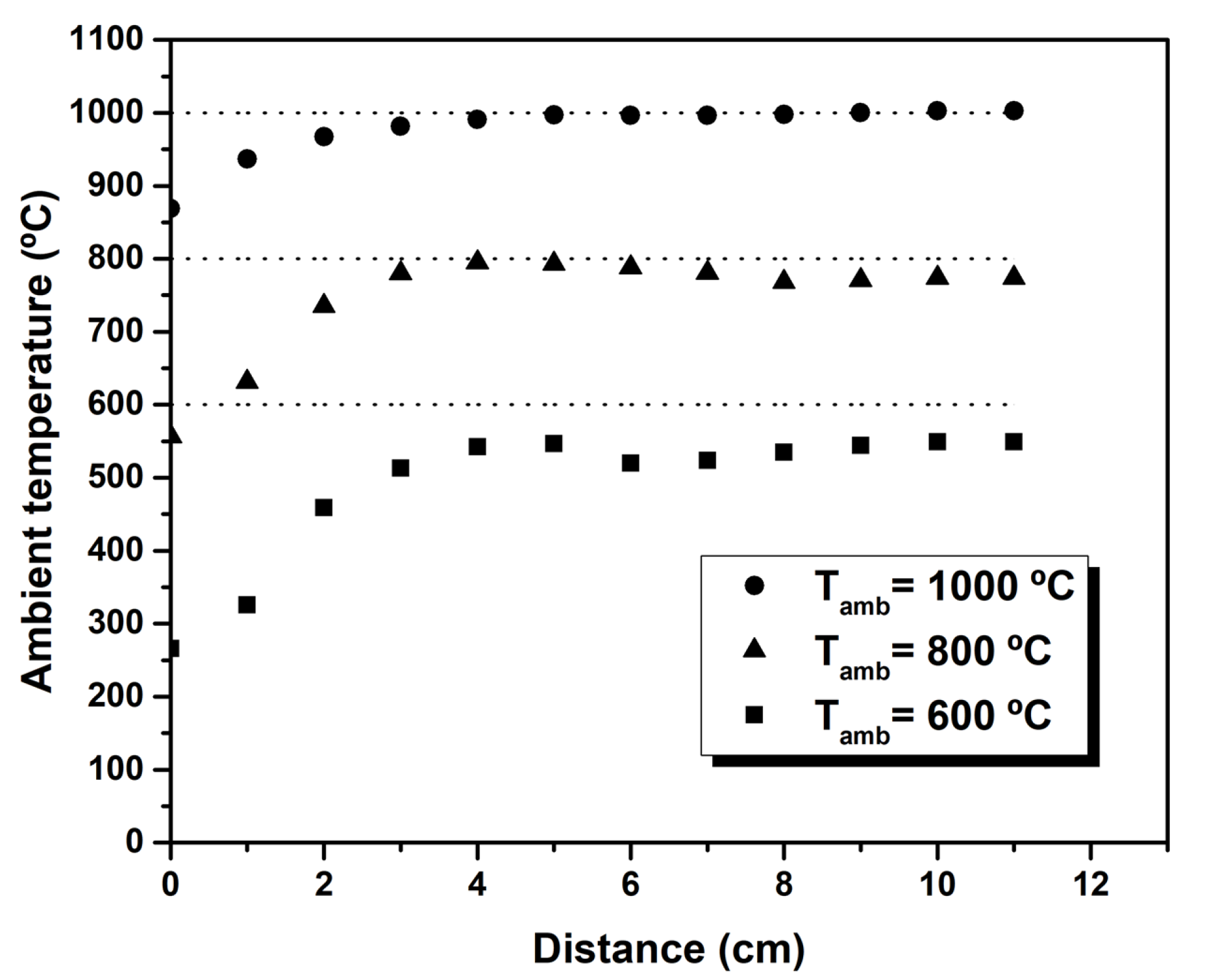
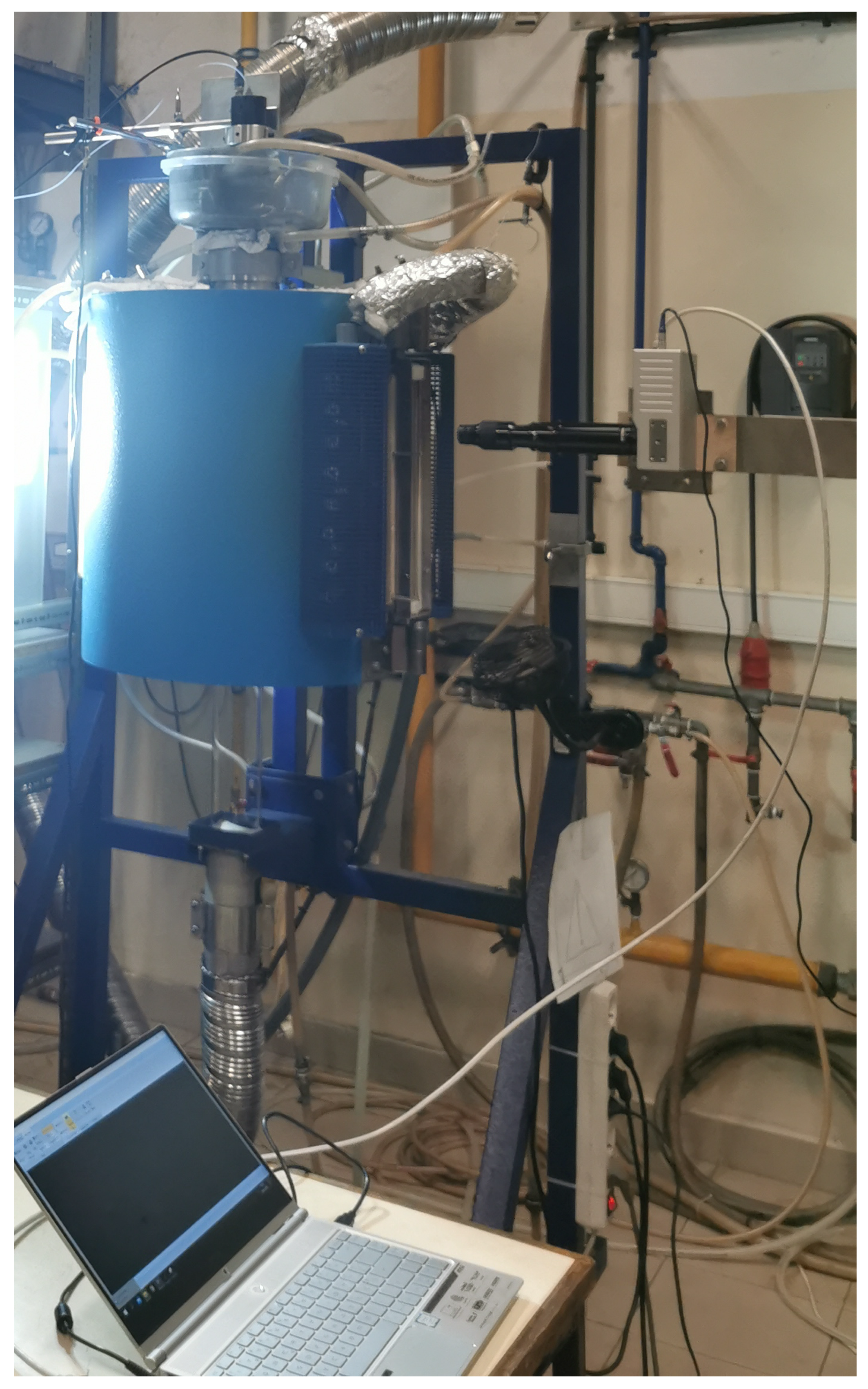
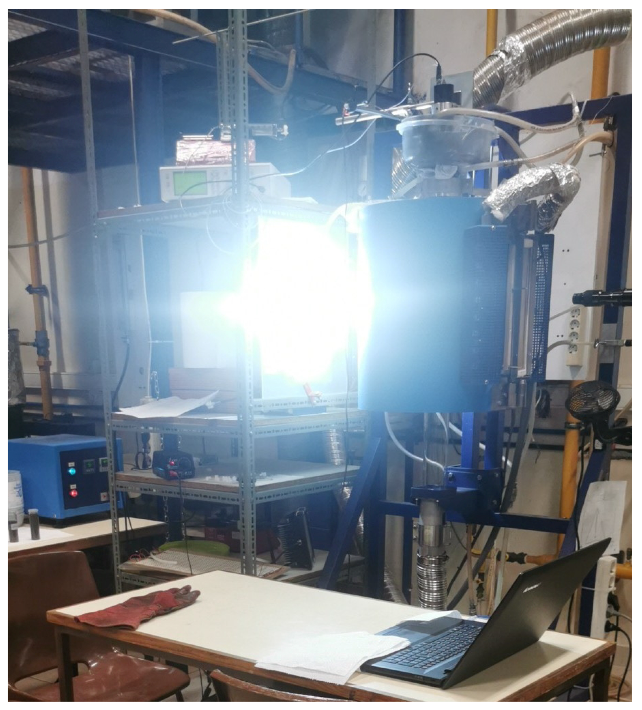
2.2. Experimental Setup
3. Results
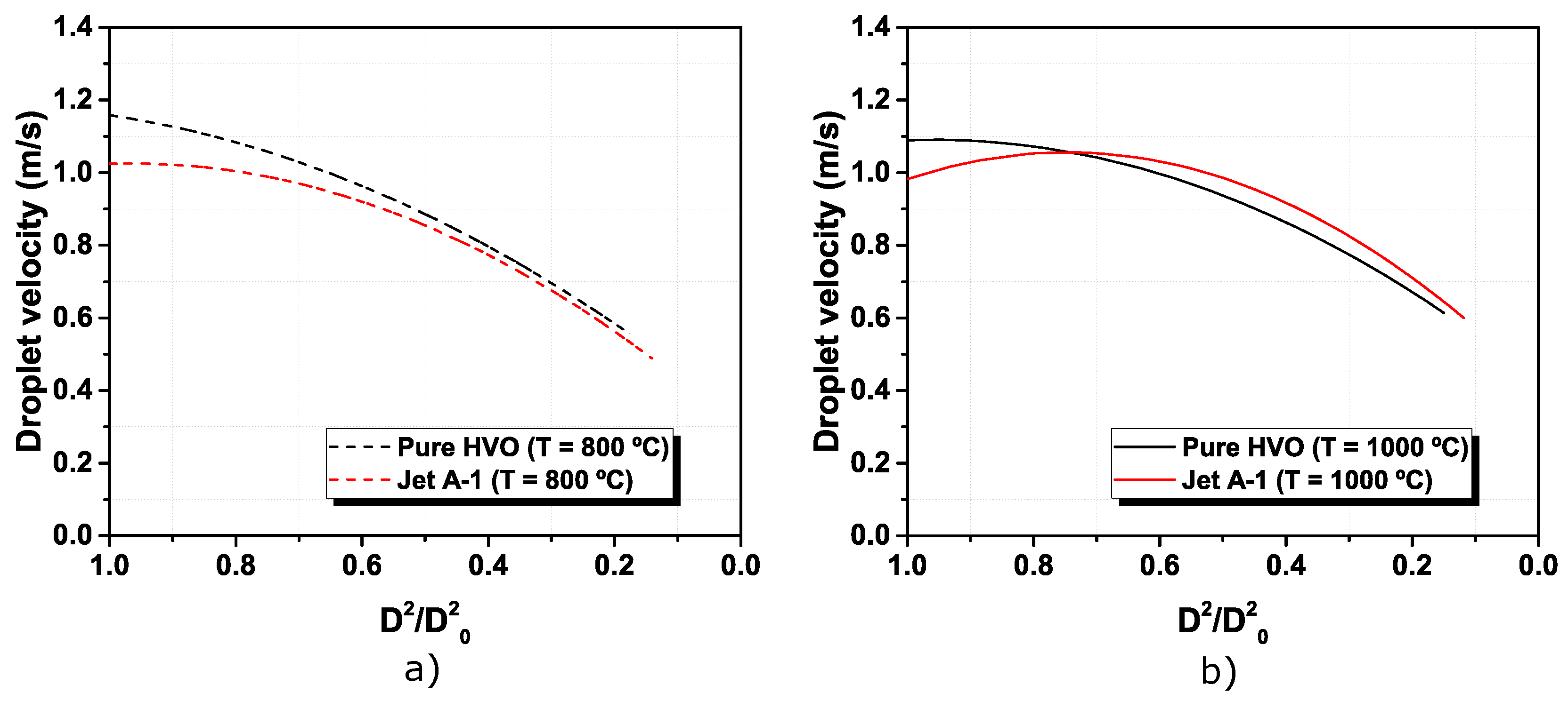
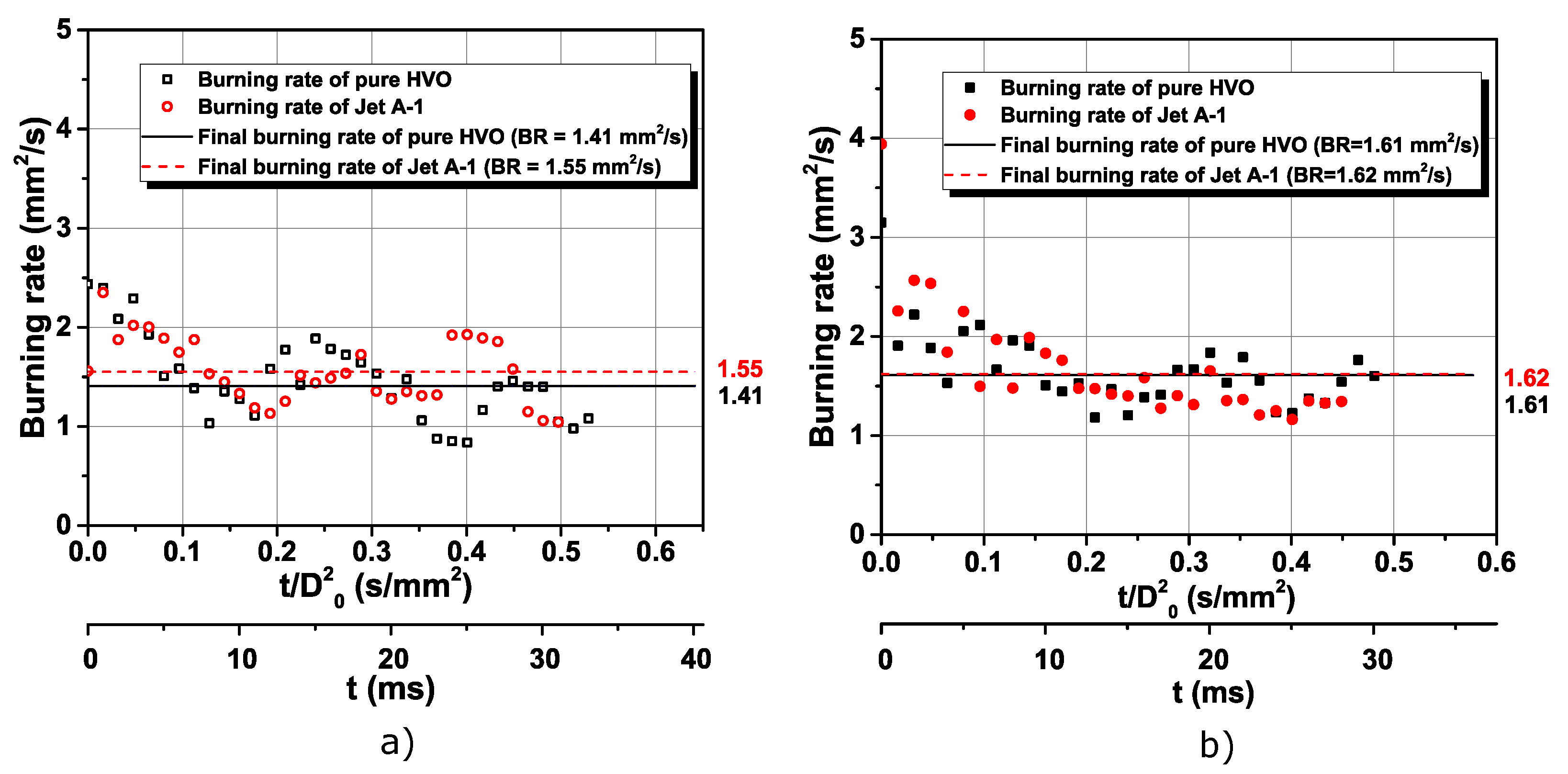
3.1. Visualization and Description of Pure Fuels Combustion
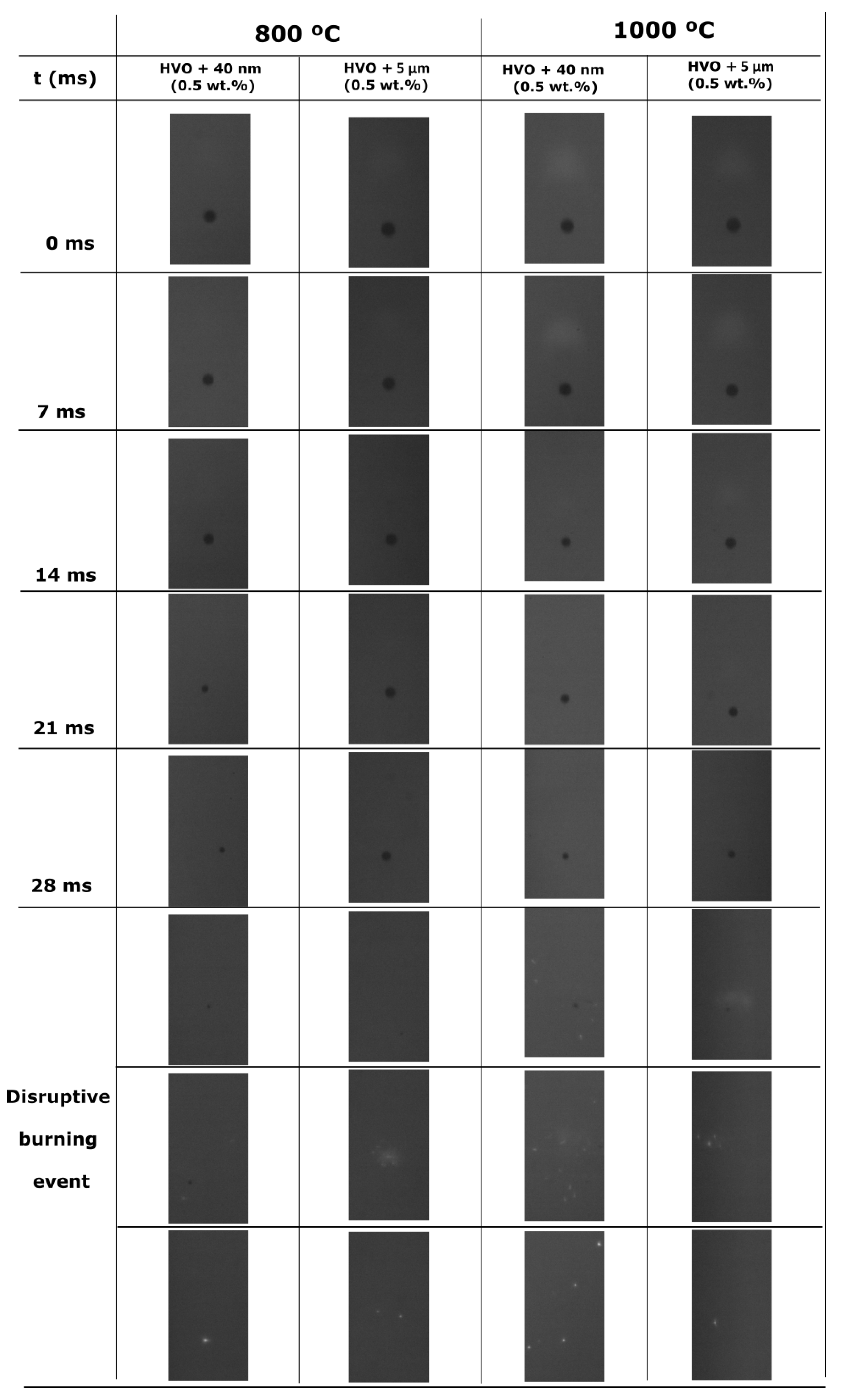
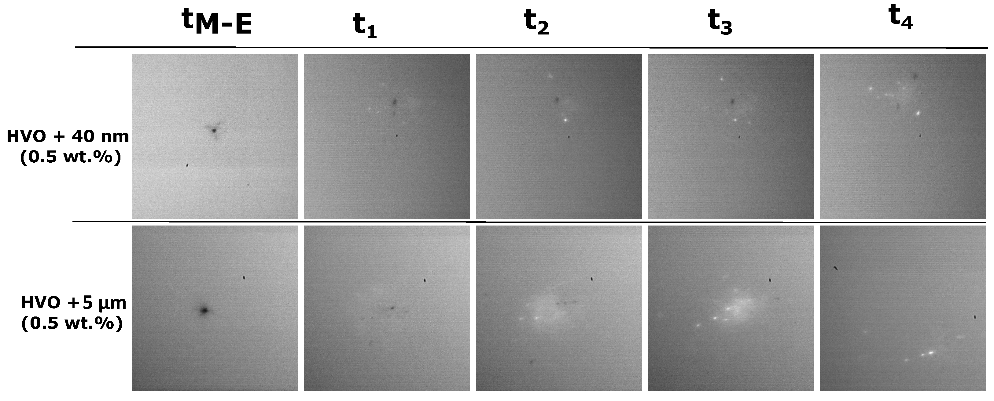
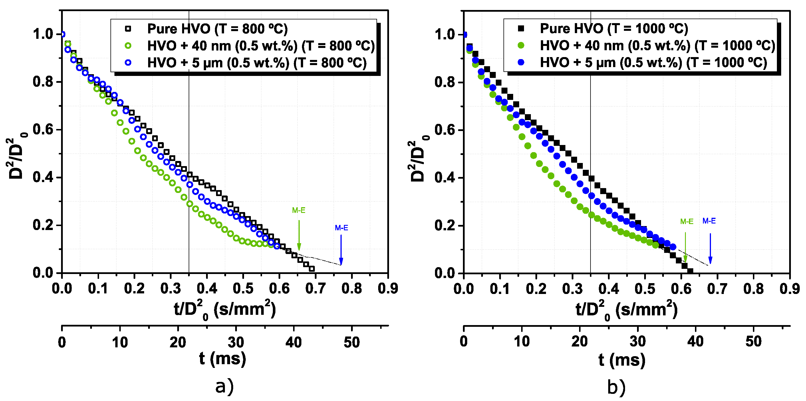
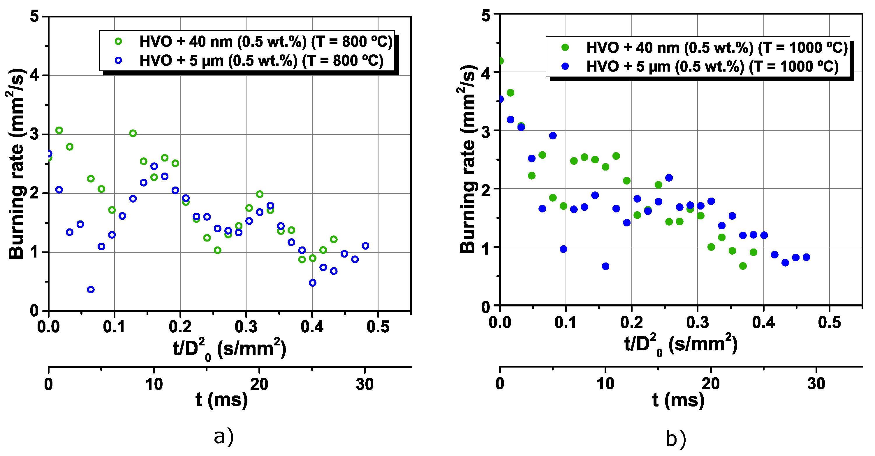
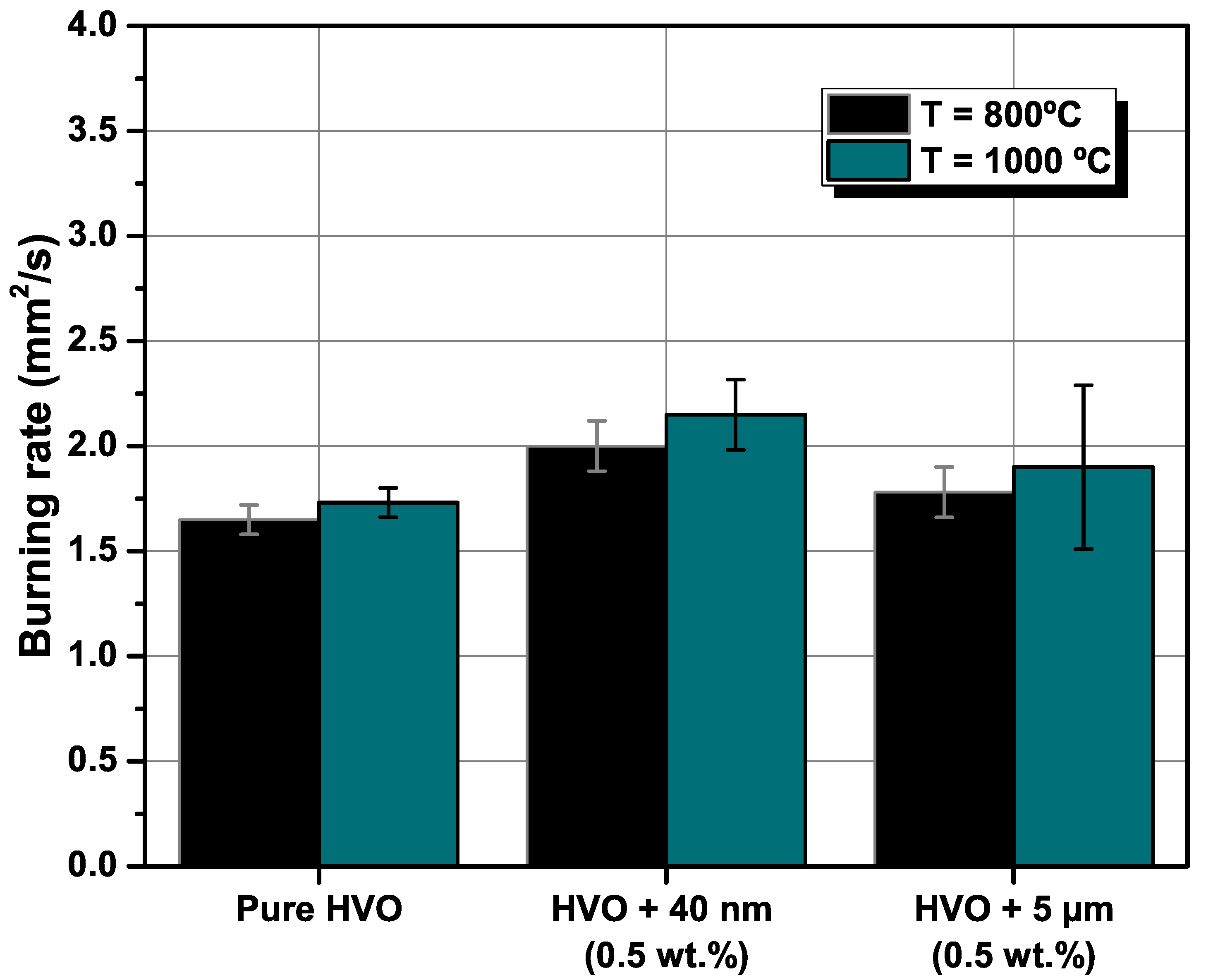
3.2. The Addition of Particles to an Alternative Jet Fuel
4. Conclusions
- Jet A-1 and HVO follow the D2 law, and no disruptive burning event was detected. However, the difference in the flame intensity was noticed, being the Jet A-1, the fuel with brighter flames, due to the aromatic content in its composition.
- The addition of aluminum particles to the HVO promotes the occurrence of disruptive burning phenomena. Thus, micro-explosions pronounce the end of the droplet lifetime for HVO + Al particles, inducing secondary atomization.
- Higher furnace temperature leads to a higher burning rate for all fuels. Finally, considering the particle size range used in this work, the most encouraging results were obtained for HVO + 40 nm (0.5 wt.%), presenting the higher burning rate and lower lifetime.
Author Contributions
Funding
Institutional Review Board Statement
Informed Consent Statement
Data Availability Statement
Conflicts of Interest
Abbreviations
| Al | Aluminum |
| ASTM | American Society for Testing and Materials |
| BR | Burning Rate |
| DTF | Drop Tube Furnace |
| HVO | Hydrotread Vegetable Oil |
| HEFA | Hydroprocessed Esters and Fatty Acids |
| JF | Jet-Fuel |
| M-E | Micro-explosion |
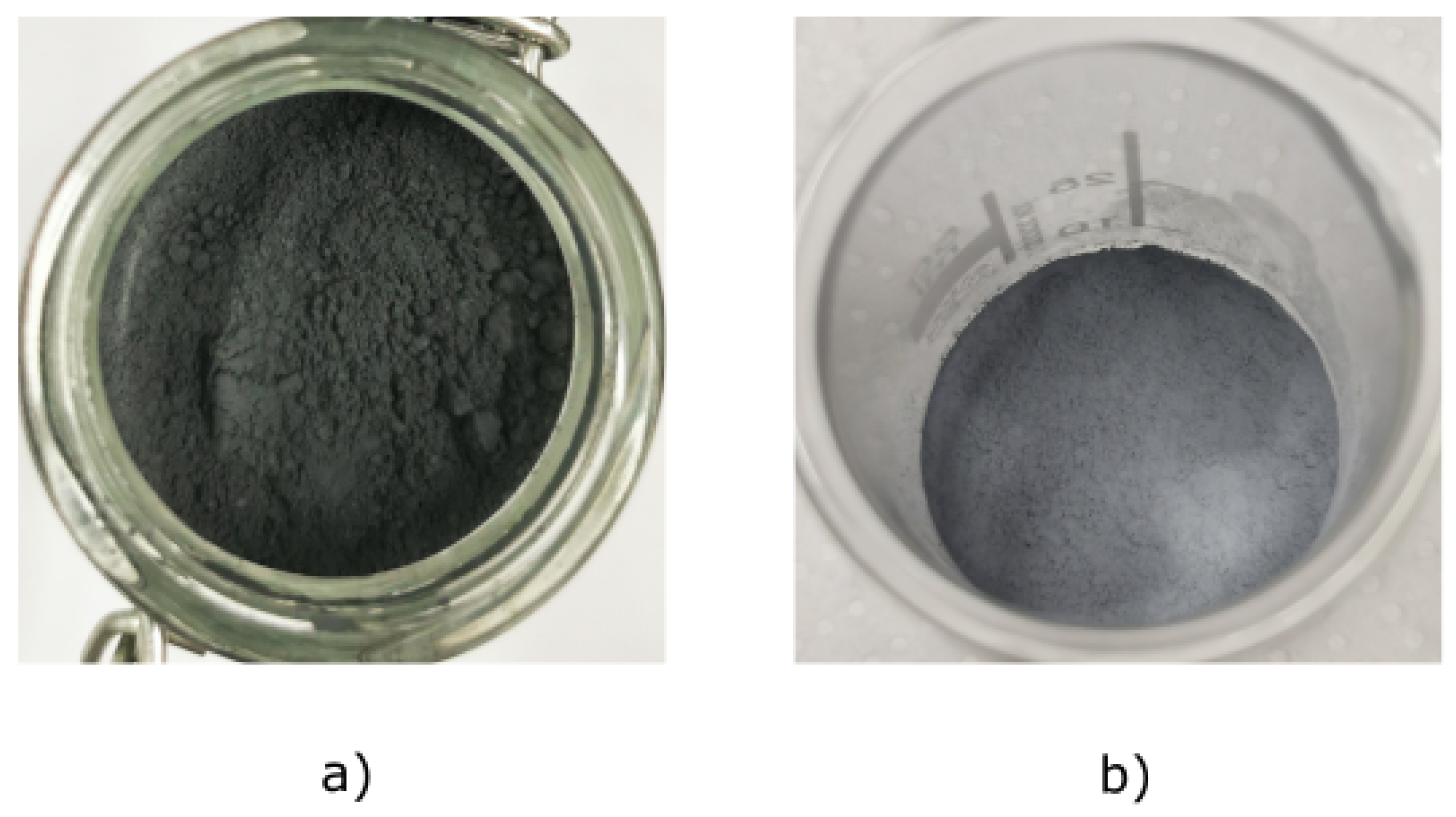
Appendix A
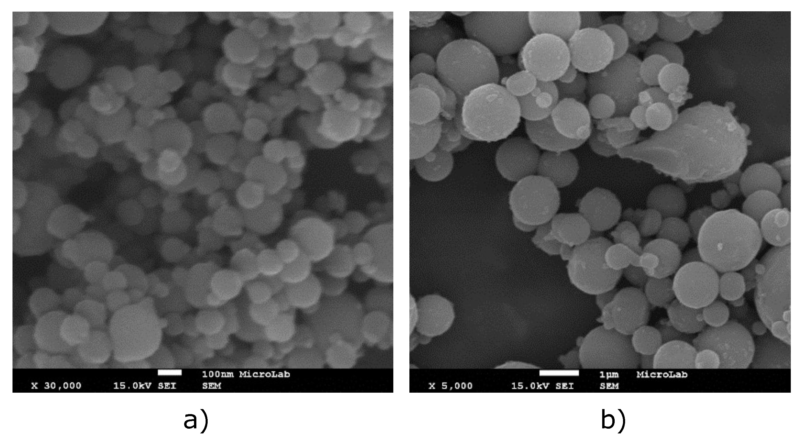
Appendix A.1. Particles Images

Appendix A.2. Experimental Setup


References
- Price, E.; Sigman, R. Combustion of aluminized solid propellants. In Solid Propellant Chemistry, Combustion, and Motor Interior Ballistics (Progress in Astronautics and Aeronautics); American Institute of Aeronautics and Astronautics: Reston, VA, USA, 2000; Volume 185, pp. 663–687. [Google Scholar]
- Berner, M.; Zarko, V.; Talawar, M. Nanoparticles of energetic materials: Synthesis and properties. Combust. Explos. Shock Waves 2013, 49, 625–647. [Google Scholar] [CrossRef]
- Sundaram, D.; Yang, V.; Zarko, V.E. Combustion of nano aluminum particles. Combust. Explos. Shock Waves 2015, 51, 173–196. [Google Scholar] [CrossRef]
- Dreizin, E.L. Metal-based reactive nanomaterials. Prog. Energy Combust. Sci. 2009, 35, 141–167. [Google Scholar] [CrossRef]
- Choudhury, P.R. Slurry fuels. Prog. Energy Combust. Sci. 1992, 18, 409–427. [Google Scholar] [CrossRef]
- Jones, M.; Li, C.H.; Afjeh, A.; Peterson, G. Experimental study of combustion characteristics of nanoscale metal and metal oxide additives in biofuel (ethanol). Nanoscale Res. Lett. 2011, 6, 246. [Google Scholar] [CrossRef] [Green Version]
- Baek, S.W.; Cho, J.H. Microexplosion of aluminum slurry droplets. Int. J. Heat Mass Transf. 1999, 42, 4475–4486. [Google Scholar]
- Wong, S.C.; Lin, A.C. Microexplosion mechanisms of aluminum/carbon slurry droplets. Combust. Flame 1992, 89, 64–76. [Google Scholar] [CrossRef]
- Valiullin, T.; Vershinina, K.; Strizhak, P. Ignition of Slurry Fuel Droplets with Different Heating Conditions. Energies 2019, 12, 4553. [Google Scholar] [CrossRef] [Green Version]
- Washburn, E.; Gross, M.; Smith, S.; Balachandar, S. Fundamental simulation of aluminum droplet combustion. In Proceedings of the 46th AIAA/ASME/SAE/ASEE Joint Propulsion Conference and Exhibit, Nashville, TN, USA, 25–28 July 2010; p. 6677. [Google Scholar]
- Beckstead, M.; Liang, Y.; Pudduppakkam, K. Numerical simulation of single aluminum particle combustion. Combust. Explos. Shock Waves 2005, 41, 622–638. [Google Scholar] [CrossRef]
- Liang, Y.; Beckstead, M. Numerical simulation of quasi-steady, single aluminum particle combustion in air. In Proceedings of the 36th AIAA Aerospace Sciences Meeting and Exhibit, Reno, NV, USA, 12–15 January 1998; p. 254. [Google Scholar]
- Megaridis, C.M.; Sirignano, W.A. Numerical modeling of a slurry droplet containing a spherical particle. J. Thermophys. Heat Transf. 1993, 7, 110–119. [Google Scholar] [CrossRef]
- Cravero, C.; Marogna, N.; Marsano, D. A Numerical Study of correlation between recirculation length and shedding frequency in vortex shedding phenomena. WSEAS Trans. Fluid Mech 2021, 16, 48–62. [Google Scholar] [CrossRef]
- Shi, L.; Yang, G.; Yao, S. Large eddy simulation of flow past a square cylinder with rounded leading corners: A comparison of 2D and 3D approaches. J. Mech. Sci. Technol. 2018, 32, 2671–2680. [Google Scholar] [CrossRef]
- Fan, X.; Lu, X. Numerical simulation of single droplet combustion characteristics in high temperature convection environment. In IOP Conference Series: Earth and Environmental Science; IOP Publishing: Bristol, UK, 2019; Volume 267, p. 062050. [Google Scholar]
- Shinjo, J.; Xia, J.; Ganippa, L.; Megaritis, A. Physics of puffing and microexplosion of emulsion fuel droplets. Phys. Fluids 2014, 26, 103302. [Google Scholar] [CrossRef]
- Takahashi, F.; Heilweil, I.; Dryer, F. Disruptive burning mechanism of free slurry droplets. Combust. Sci. Technol. 1989, 65, 151–165. [Google Scholar] [CrossRef]
- Yetter, R.A.; Risha, G.A.; Son, S.F. Metal particle combustion and nanotechnology. Proc. Combust. Inst. 2009, 32, 1819–1838. [Google Scholar] [CrossRef]
- Basu, S.; Miglani, A. Combustion and heat transfer characteristics of nanofluid fuel droplets: A short review. Int. J. Heat Mass Transf. 2016, 96, 482–503. [Google Scholar] [CrossRef]
- Tyagi, H.; Phelan, P.E.; Prasher, R.; Peck, R.; Lee, T.; Pacheco, J.R.; Arentzen, P. Increased hot-plate ignition probability for nanoparticle-laden diesel fuel. Nano Lett. 2008, 8, 1410–1416. [Google Scholar] [CrossRef]
- Gan, Y.; Qiao, L. Combustion characteristics of fuel droplets with addition of nano and micron-sized aluminum particles. Combust. Flame 2011, 158, 354–368. [Google Scholar] [CrossRef]
- Javed, I.; Baek, S.W.; Waheed, K. Effects of dense concentrations of aluminum nanoparticles on the evaporation behavior of kerosene droplet at elevated temperatures: The phenomenon of microexplosion. Exp. Therm. Fluid Sci. 2014, 56, 33–44. [Google Scholar] [CrossRef]
- Ojha, P.K.; Maji, R.; Karmakar, S. Effect of crystallinity on droplet regression and disruptive burning characteristics of nanofuel droplets containing amorphous and crystalline boron nanoparticles. Combust. Flame 2018, 188, 412–427. [Google Scholar] [CrossRef]
- Singh, G.; Esmaeilpour, M.; Ratner, A. Effect of carbon-based nanoparticles on the ignition, combustion and flame characteristics of crude oil droplets. Energy 2020, 197, 117227. [Google Scholar] [CrossRef] [Green Version]
- Tanvir, S.; Qiao, L. Effect of addition of energetic nanoparticles on droplet-burning rate of liquid fuels. J. Propuls. Power 2015, 31, 408–415. [Google Scholar] [CrossRef] [Green Version]
- Tanvir, S.; Biswas, S.; Qiao, L. Evaporation characteristics of ethanol droplets containing graphite nanoparticles under infrared radiation. Int. J. Heat Mass Transf. 2017, 114, 541–549. [Google Scholar] [CrossRef]
- Emekwuru, N.G. Nanofuel droplet evaporation processes. J. Indian Inst. Sci. 2019, 99, 43–58. [Google Scholar] [CrossRef]
- Gan, Y.; Qiao, L. Radiation-enhanced evaporation of ethanol fuel containing suspended metal nanoparticles. Int. J. Heat Mass Transf. 2012, 55, 5777–5782. [Google Scholar] [CrossRef]
- Ghamari, M.; Ratner, A. Combustion characteristics of colloidal droplets of jet fuel and carbon based nanoparticles. Fuel 2017, 188, 182–189. [Google Scholar] [CrossRef]
- Xiu-tian feng, E.; Zhi, X.; Zhang, Y.; Li, C.; Zou, J.J.; Zhang, X.; Wang, L. Jet fuel containing ligand-protecting energetic nanoparticles: A case study of boron in JP-10. Chem. Eng. Sci. 2015, 129, 9–13. [Google Scholar]
- Ng, K.S.; Farooq, D.; Yang, A. Global biorenewable development strategies for sustainable aviation fuel production. Renew. Sustain. Energy Rev. 2021, 150, 111502. [Google Scholar] [CrossRef]
- Hemighaus, G.; Boval, T.; Bacha, J.; Barnes, F.; Franklin, M.; Gibbs, L.; Hogue, N.; Jones, J.; Lesnini, D.; Lind, J.; et al. Aviation Fuels Technical Review; Chevron Products Company: San Ramon, CA, USA, 2006. [Google Scholar]
- Rochelle, D.; Najafi, H. A review of the effect of biodiesel on gas turbine emissions and performance. Renew. Sustain. Energy Rev. 2019, 105, 129–137. [Google Scholar] [CrossRef]
- Yilmaz, N.; Atmanli, A. Sustainable alternative fuels in aviation. Energy 2017, 140, 1378–1386. [Google Scholar] [CrossRef]
- Hari, T.K.; Yaakob, Z.; Binitha, N.N. Aviation biofuel from renewable resources: Routes, opportunities and challenges. Renew. Sustain. Energy Rev. 2015, 42, 1234–1244. [Google Scholar] [CrossRef]
- Patruno, A.; Amicarelli, V.; Lagioia, G. Aviation Fuel Evolution: A Review. 2017. Available online: www.asecu.gr/files/13th/conf_files/The-Aviation-Fuel-Evolution-A-Review.pdf (accessed on 5 January 2022).
- Blakey, S.; Rye, L.; Wilson, C.W. Aviation gas turbine alternative fuels: A review. Proc. Combust. Inst. 2011, 33, 2863–2885. [Google Scholar] [CrossRef]
- Yang, J.; Xin, Z.; Corscadden, K.; Niu, H. An overview on performance characteristics of bio-jet fuels. Fuel 2019, 237, 916–936. [Google Scholar] [CrossRef]
- Pizziol, B.; Costa, M.; Panão, M.O.; Silva, A. Multiple impinging jet air-assisted atomization. Exp. Therm. Fluid Sci. 2018, 96, 303–310. [Google Scholar] [CrossRef] [Green Version]
- Pacheco, G.; Silva, A.; Costa, M. Single-Droplet Combustion of Jet A-1, Hydroprocessed Vegetable Oil, and Their Blends in a Drop-Tube Furnace. Energy Fuels 2021, 35, 7232–7241. [Google Scholar] [CrossRef]
- Simacek, P.; Soucek, I.; Pospisil, M.; Vrtiska, D.; Kittel, H. Impact of hydrotreated vegetable oil and biodiesel on properties in blends with mineral diesel fuel. Therm. Sci. 2019, 23, 1769–1777. [Google Scholar] [CrossRef]
- Wang, L.; Chen, H.; Witharana, S. Rheology of nanofluids: A review. Recent Pat. Nanotechnol. 2013, 7, 232–246. [Google Scholar] [CrossRef]
- Arshad, A.; Jabbal, M.; Yan, Y.; Reay, D. A review on graphene based nanofluids: Preparation, characterization and applications. J. Mol. Liq. 2019, 279, 444–484. [Google Scholar] [CrossRef]
- Moita, A.S.; Laurência, C.; Ramos, J.A.; Prazeres, D.M.F.; Moreira, A.L.N. Dynamics of droplets of biological fluids on smooth superhydrophobic surfaces under electrostatic actuation. J. Bionic Eng. 2016, 13, 220–234. [Google Scholar] [CrossRef]
- Tanvir, S.; Qiao, L. Surface tension of nanofluid-type fuels containing suspended nanomaterials. Nanoscale Res. Lett. 2012, 7, 226. [Google Scholar] [CrossRef] [Green Version]
- Clayton, R.; Back, L. Physical and chemical characteristics of cenospheres from the combustion of heavy fuel oil. J. Eng. Gas Turbines Power. 1989, 679–684. [Google Scholar] [CrossRef]
- Jiang, L.; Elbaz, A.M.; Guida, P.; Al-Noman, S.M.; AlGhamdi, I.A.; Saxena, S.; Roberts, W.L. Cenosphere formation during single-droplet combustion of heavy fuel oil. Energy Fuels 2019, 33, 1570–1581. [Google Scholar] [CrossRef]
- Ferrão, I.A.; Silva, A.R.; Moita, A.S.; Mendes, M.A.; Costa, M.M. Combustion characteristics of a single droplet of hydroprocessed vegetable oil blended with aluminum nanoparticles in a drop tube furnace. Fuel 2021, 302, 121160. [Google Scholar] [CrossRef]
- Stöhr, M.; Ruoff, S.; Rauch, B.; Meier, W.; Le Clercq, P. Droplet vaporization for conventional and alternative jet fuels at realistic temperature conditions: Systematic measurements and numerical modeling. Proc. Combust. Inst. 2021, 38, 3269–3276. [Google Scholar] [CrossRef]
- Liu, Y.C.; Savas, A.J.; Avedisian, C.T. The spherically symmetric droplet burning characteristics of Jet-A and biofuels derived from camelina and tallow. Fuel 2013, 108, 824–832. [Google Scholar] [CrossRef]
- Buffi, M.; Valera-Medina, A.; Marsh, R.; Pugh, D.; Giles, A.; Runyon, J.; Chiaramonti, D. Emissions characterization tests for hydrotreated renewable jet fuel from used cooking oil and its blends. Appl. Energy 2017, 201, 84–93. [Google Scholar] [CrossRef]
- Chishty, W.A.; Davison, C.R.; Bird, J.; Chan, T.; Cuddihy, K.; McCurdy, M.; Barton, P.; Krasteva, A.; Poitras, P. Emissions assessment of alternative aviation fuel at simulated altitudes. In Proceedings of the Turbo Expo: Power for Land, Sea, and Air, Vancouver, BC, Canada, 6–10 June 2011; Volume 54617, pp. 51–61. [Google Scholar]
- Gan, Y.; Lim, Y.S.; Qiao, L. Combustion of nanofluid fuels with the addition of boron and iron particles at dilute and dense concentrations. Combust. Flame 2012, 159, 1732–1740. [Google Scholar] [CrossRef]
- Bennewitz, J.W.; Badakhshan, A.; Talley, D.G. Combustion characteristics of suspended hydrocarbon fuel droplets with various nanoenergetic additives. Combust. Sci. Technol. 2021, 193, 2111–2136. [Google Scholar] [CrossRef]
- Guerieri, P.M.; DeCarlo, S.; Eichhorn, B.; Connell, T.; Yetter, R.A.; Tang, X.; Hicks, Z.; Bowen, K.H.; Zachariah, M.R. Molecular aluminum additive for burn enhancement of hydrocarbon fuels. J. Phys. Chem. A 2015, 119, 11084–11093. [Google Scholar] [CrossRef]
- Li, H.; Rosebrock, C.D.; Wu, Y.; Wriedt, T.; Mädler, L. Single droplet combustion of precursor/solvent solutions for nanoparticle production: Optical diagnostics on single isolated burning droplets with micro-explosions. Proc. Combust. Inst. 2019, 37, 1203–1211. [Google Scholar] [CrossRef]
- Kim, D.M.; Baek, S.W.; Yoon, J. Ignition characteristics of kerosene droplets with the addition of aluminum nanoparticles at elevated temperature and pressure. Combust. Flame 2016, 173, 106–113. [Google Scholar] [CrossRef]
- Aboalhamayie, A.; Festa, L.; Ghamari, M. Evaporation rate of colloidal droplets of jet fuel and carbon-based nanoparticles: Effect of thermal conductivity. Nanomaterials 2019, 9, 1297. [Google Scholar] [CrossRef] [PubMed] [Green Version]


| Parameter | Standard Limit | Jet A-1 | HVO | |
|---|---|---|---|---|
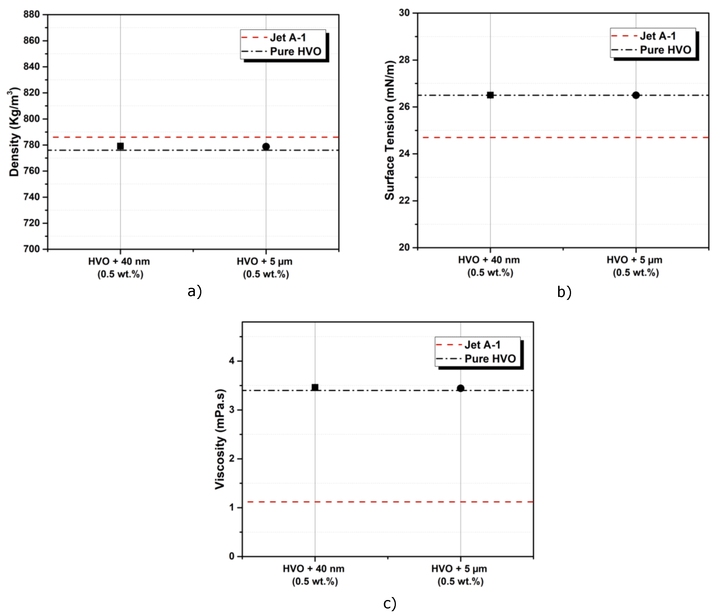
| Density (kg/m3) (at 20 °C) | 771–836 | 798 | 780.6 | |
| Kinematic viscosity (mm2/s) (at 25 °C) | 1.40 | 4.33 | ||
| Surface tension (N/m) (at 20 °C) | 0.0247 | 0.0265 | ||
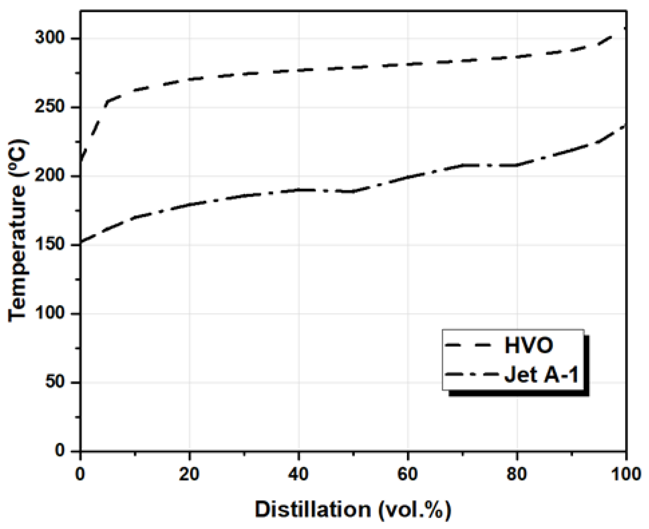
| Distillation | 10 vol.% (°C) | 170 | 262 | |
| 50 vol.% (°C) | 189 | 279 | ||
| 90 vol.% (°C) | 219 | 291 | ||
| Final boiling point (°C) | Max. 300 | 237 | 308 | |
| Flash point (°C) | Min. 38.0 | 38 | 77 | |
| Cloud point (°C) | −26 | −34 | ||
| Sulfur (wt.%) | Max. 30.0 | 0.3 | 0.09 | |
| Aromatics (wt.%) | Max. 25.0 (vol.%) | 13.8 | 0 | |
| Lower heating value (MJ/kg) | Min. 42.8 | 43 | 43.9 | |
| Higher heating value (MJ/kg) | 47 | 47.1 | ||
| Hydrogen content | 14.5 | 15.4 | ||
| Carbon content | 84.6 | 85.5 | ||
| H/C ratio | 1.91 | 2.18 | ||
| Carbon number | C8–C16 | C15–C18 | ||
Publisher’s Note: MDPI stays neutral with regard to jurisdictional claims in published maps and institutional affiliations. |
© 2022 by the authors. Licensee MDPI, Basel, Switzerland. This article is an open access article distributed under the terms and conditions of the Creative Commons Attribution (CC BY) license (https://creativecommons.org/licenses/by/4.0/).
Share and Cite
Ferrão, I.A.S.; Mendes, M.A.A.; Moita, A.S.O.H.; Silva, A.R.R. The Addition of Particles to an Alternative Jet Fuel. Fuels 2022, 3, 184-206. https://doi.org/10.3390/fuels3020012
Ferrão IAS, Mendes MAA, Moita ASOH, Silva ARR. The Addition of Particles to an Alternative Jet Fuel. Fuels. 2022; 3(2):184-206. https://doi.org/10.3390/fuels3020012
Chicago/Turabian StyleFerrão, Inês A. S., Miguel A. A. Mendes, Ana S. O. H. Moita, and André R. R. Silva. 2022. "The Addition of Particles to an Alternative Jet Fuel" Fuels 3, no. 2: 184-206. https://doi.org/10.3390/fuels3020012