
Organic Waste Gasification: A Selective Review


Detonation Laboratory, Department of Combustion and Explosion, Semenov Federal Research Center for Chemical Physics of the Russian Academy of Sciences, Moscow 119991, Russia
Fuels 2021, 2(4), 556-650; https://doi.org/10.3390/fuels2040033
Submission received: 15 November 2021
/
Revised: 22 November 2021
/
Accepted: 30 November 2021
/
Published: 7 December 2021
(This article belongs to the Special Issue Feature Papers in Fuels)
Abstract
:This review considers the selective studies on environmentally friendly, combustion-free, allothermal, atmospheric-pressure, noncatalytic, direct H2O/CO2 gasification of organic feedstocks like biomass, sewage sludge wastes (SSW) and municipal solid wastes (MSW) to demonstrate the pros and cons of the approaches and provide future perspectives. The environmental friendliness of H2O/CO2 gasification is well known as it is accompanied by considerably less harmful emissions into the environment as compared to O2/air gasification. Comparative analysis of the various gasification technologies includes low-temperature H2O/CO2 gasification at temperatures up to 1000 °C, high-temperature plasma- and solar-assisted H2O/CO2 gasification at temperatures above 1200 °C, and an innovative gasification technology applying ultra-superheated steam (USS) with temperatures above 2000 °C obtained by pulsed or continuous gaseous detonations. Analysis shows that in terms of such characteristics as the carbon conversion efficiency (CCE), tar and char content, and the content of harmful by-products the plasma and detonation USS gasification technologies are most promising. However, as compared with plasma gasification, detonation USS gasification does not need enormous electric power with unnecessary and energy-consuming gas–plasma transition.
1. Introduction
Modern society is faced with the problem of clean processing/utilization of organic wastes. Thermal processing of these materials is considered the most suitable solution due to relatively low environmental impact and partial recovery of energy and material resources. Available technologies of thermal processing are based on combustion/incineration, pyrolysis, and gasification, as well as on their combinations [1,2,3,4]. Combustion is the transformation of the matter due to overall exothermic self-accelerating chemical reactions induced by molecular/turbulent mass and energy transport. Pyrolysis and gasification usually involve endothermic thermal degradation of the matter in the absence/presence of gasifying agent, respectively. A mild form of pyrolysis, torrefaction, is another emerging technology aimed at improving the energy density, calorific value, and grindability of feedstocks by their heating in the temperature range of 200–300 °C [5].
Combustion of wastes results in the formation of airborne gaseous pollutants, like polyaromatic hydrocarbons (PAH), NOx, SOx, HCl, furans, dioxins, as well as organic and inorganic aerosol particulate, fly ash, ashes, etc. Thus, biomass consists of lignin, carbohydrates, extractives, and inorganic fractions that are present in different amounts. In the wood smoke, such toxic compounds as PAH, polychlorinated dibenzo-p-dioxins (PCDDs), polychlorinated dibenzofurans (PCDFs), and polychlorinated biphenyls (PCBs) are detected. Alkalis (potassium, calcium, silicon, etc.) present in the biomass can react with other minerals and cause fouling and slagging [6]. The same relates to SSW. The main groups of organic solids in SSW are carbohydrates, proteins, fats, and oils. During combustion/incineration of SSW, dioxins, and furans, as well as nitrogen, chlorine, and sulfur compounds are released as gaseous pollutants in various forms. As for MSW, it is heterogeneous and contains a variety of materials (paper, wood, yard trimmings, food, plastics, metals, glass, and possibly hazardous materials) with a high fraction of organic compounds (over 70–80%), which implies a possibility of appropriate separation before incineration. Recent studies show that burning biomass, SSW, and MSW with fossil fuels (coal) has a positive impact both on the environment and the economics of power generation [7,8]. This necessitates cleaning of the flue gas to meet strict emission limits.
Pyrolysis and gasification of wastes can potentially reduce the production of the various pollutants due to the absence or reduced amount of oxygen. However, for providing the required heat for pyrolysis and gasification reactions, the existing autothermal and allothermal technologies usually use the combustion of fossil fuels and/or feedstock or apply air/O2 as gasifying agents [9,10]. The use of combustion processes is then again related to harmful pollutants, whereas the use of air/O2 as gasifying agents promotes the formation of dioxins and furans. In view of it, the use of other substances as gasifying agents, like steam [11,12] and/or CO2 [13,14] looks very attractive, especially when the heat required for gasification is obtained by environmentally clean technologies (solar [15], microwave (MW) [16,17], plasma [18,19], etc.) different from combustion. Pyrolysis and gasification are usually implemented at temperatures 400–1000 °C and result in production of gases like H2, CO, CO2, light hydrocarbons, tar, and char [20,21]. The technologies based on gasification of solids and liquids (coal, lignin, biomass, plastics, crude oil, etc.), especially with steam as a gasifying agent, are used for the production of H2, syngas (a mixture of H2 and CO), olefins, etc. [22,23]. Large-scale coal gasification plants usually use high-pressure O2- or air-blown technologies [24]. However, for decentralized gasification of organic wastes atmospheric-pressure H2O/CO2 gasification is considered as promising alternative. In the small and medium-scale range of gasification plants, atmospheric-pressure H2O/CO2 gasification of organic wastes provides a significantly higher syngas quality than air-blown gasification. N2-free syngas possesses higher heating values and H2 content over 60vol%. This makes such technologies appropriate for the conversion of biomass, SSW, and MSW into synthetic fuels such as methanol, dimethyl ether, substitute natural gas (SNG), and Fischer–Tropsch (FT) diesel [25]. The conversion efficiency and gas yields are known to significantly increase with the pyrolysis/gasification temperature, whereas the yields of harmful substances are known to significantly decrease in these conditions. When the process temperatures exceed 1200 °C, further conversion steps are not needed anymore as the production of H2 and CO tends to maximum, and other side by-products do not form at all [26]. Furthermore, the conversion efficiency depends on the availability of catalytically active material, which is in some cases contained in biomass ash, and in other cases is present in gasifier bed material or purposely added to the process. The gasification of wastes with supercritical water (at above 374 °C and 22.1 MPa), despite many potential advantages, requires very high operation pressures, thus making the technology costly [27]. There is also interest in co-gasification of various carbon containing materials (CCMs) with different physical properties, e.g., wood and plastics, MSW and coal, etc., due to synergy effects.
Thus, there is a need for the technologies based on combustion-free, atmospheric pressure H2O/CO2 gasification of organic wastes with temperatures above 1200 °C. Processing of organic wastes in such an environment will be accompanied by their complete gasification to the syngas of high quality. The target value of the H2/CO ratio is always possible to adjust [14,28]. The resultant syngas could be used as a fuel gas for producing heat and/or electricity for other purposes. The S and Cl containing wastes will be transformed to the corresponding liquid acids (after steam condensation [29]), while solid inorganic materials will be transformed to the molten slag consisting of simple oxides and salts, an excellent construction material.
One of the known technological solutions in this respect is atmospheric-pressure plasma-based gasification, in particular steam-blown plasma gasification [30], known for its capability of treating complex feedstocks such as SSW and MSW while producing syngas of high purity and energy content. In this case, the heat required for gasification reactions comes solely from electricity to produce plasma torches in so-called plasma guns. In plasma gasifiers, tar is thermally decomposed into H2 and CH4 and ash is converted into vitrified and inert slag [31,32,33] due to high (over 1300 °C) effective temperatures of a heat carrier gas and availability of very chemically active species enhancing gasification reactions. However, for running plasma guns with such high temperatures enormous electricity consumption is required [31]. Other challenges are the need for advanced refractory materials for reactor casing and electrodes [34,35,36].
Another solution is based on using the USS with a temperature above 2000 °C obtained by burning environmentally clean H2–O2 mixture [37]. Combustion of a mixture of syngas with steam and O2 to obtain such a temperature could be an alternative solution [38]. Due to the wide flammability limits of H2, the amount of CO2 (greenhouse gas, GHG) in the combustion products could be considerably less than in the combustion products of fossil fuel. Such technologies are competitive to the plasma-based technologies as they do not involve energy losses due to unnecessary and energy-consuming transformation of electric energy to the thermal energy of a heat carrier gas through the state of plasma. Such technologies are capable of providing efficient processing of wastes of arbitrary chemical and morphological composition with full utilization of available resources without harmful emissions into water bodies and atmosphere. However, these technologies have not yet been implemented due to problems with the thermal insulation of combustors and gasifiers.
In our patent [39], we proposed a new method and devices for obtaining USS with temperatures above 2000 °C at atmospheric pressure, in which the problems of thermal insulation of combustion devices and reactors are solved by substituting conventional combustion by detonation in a pulse- or continuous-detonation steam superheaters (so-called pulsed or continuous USS guns) by means of cyclic or continuously rotating gaseous detonations of ternary fuel gas–oxidizer–steam mixture. Detonation is the transformation of the matter due to overall exothermic self-accelerating chemical reactions induced by volumetric compression and heating in strong self-sustaining shock waves (SWs). So far detonation of high explosives was primarily used for disposal of hazardous wastes like explosives and highly reactive materials (nitrocompounds, organic peroxides, etc. [40]). In patents [41,42], the novel gasification technologies based on pulsed USS guns are applied to USS gasification of CCMs [41] and to fly ash decontamination [42]. The fundamentals of gaseous and spray detonations and the operation principles of pulse-detonation and continuous-detonation combustors for propulsion purposes were reviewed in [43] and [44], respectively. Syngas, H2, natural gas, C3H8, etc. can be used as fuel gas, while pure air, O2, or air enriched with O2 can be used as oxidizer.
In the literature, there are several excellent books on biomass, SSW and MSW management and the fundamentals of incineration, pyrolysis, and gasification technologies (see, e.g., [1,2,3,4]), as well as multiple reviews on feedstock pretreatment/aftertreatment, advanced autothermal and allothermal, catalytic and noncatalytic gasifier designs and performances [31,45,46,47,48,49,50,51,52,53,54,55,56,57,58,59,60,61], and downstream technologies and syngas applications ([1,2,3,4,28]). We refer an interested reader to these references and do not consider these issues herein. Thus, the objective of this review is to consider the selective studies on environmentally friendly, combustion-free, allothermal, atmospheric-pressure, noncatalytic, direct H2O/CO2 gasification of organic feedstocks like biomass, SSW, and MSW, and demonstrate the pros and cons of the approaches and provide future perspectives. The main issue addressed is the effect of gasification temperature and H2O/CO2-to-feedstock ratio on the gasification efficiency, syngas quality and yield, as well as the feasibility of in-situ control of syngas composition. These objectives and issues are the novel and distinctive features of the present review.
2. Definitions
This section briefly provides the definitions of main terms and indices used in the paper, as well as the literature search approach and methodology limitations. Further details can be found, e.g., in [1,2,3,4].
2.1. Feedstocks
Biomass comprises a variety of CCMs with different properties consisting predominantly of C, H, and O elements. It is derived from biological objects using photosynthesis to transform solar energy into carbohydrates. Agricultural and forestry wastes comprise wood sawdust (WS), crop waste products; and foliage which are often uneconomical to transport. Wet biomass sources include food wastes, SSW, animal slurry, etc.
SSW is a heterogeneous by-product of municipal or industrial wastewater treatment with high moisture content (up to 80%) and with a range of organic contaminants.
MSW is a heterogeneous feedstock containing materials with widely varying compositions, sizes, and shapes. MSW of typical composition is represented by 47wt% paper and cardboard, 21wt% food waste, 12wt% glass, 3wt% iron and its oxides, 5wt% plastics, 5wt% wood, 3wt% rubber and leather, 2wt% textiles, 2wt% calcium carbonate, i.e., CCMs constitute over 80%.
Refuse derived fuel (RDF) is a processed form of MSW. Conversion of MSW into RDF includes several operations like shredding, screening, sorting, drying, and pelletization to improve the homogeneity of the material and its handling characteristics. The RDF possesses a significantly higher energy density than MSW.
Hazardous wastes (HW) are classified according to the form in which they appear and according to the hazardous material content. A list of waste materials includes hazardous liquids and gases (PCB-containing oils, chlorinated fluorocarbons (CFCs) and various widely used solvents); hospital solid wastes (HSW); contaminated soils; low level radioactive wastes; and other wastes (military, asbestos materials, etc.).
Coal is a solid fossil fuel with high C content and various fractions of H, O, N, and S. Coals are differentiated into categories in terms of the descending LHV, composition, content of volatiles and moisture, namely, anthracite, bituminous, sub-bituminous, and lignite. This review deals mainly with biomass, SSW and MSW, despite some technologies include co-gasification with coal.
2.2. Processing Technologies
Incineration is full oxidative combustion converting CCMs in an O2-rich environment, typically at temperatures above 800 °C, to a flue gas composed primarily of CO2 and H2O with harmful by-products. Inorganic materials are converted to ash. This is the most common and well-proven thermal process using a variety of combustible materials.
Pyrolysis is thermal decomposition of CCM due to the use of an external heat source, typically at temperatures 400–900 °C, in the absence or at small amount of free oxygen. During pyrolysis, volatile portions of CCMs are driven off, resulting in the production of syngas composed mainly of H2, CO, CO2, CH4, as well as higher hydrocarbons and harmful by-products. The condensed residue of the CCMs is left as tar and char. Inorganic materials form bottom ash.
Gasification is the thermal process of converting CCMs to syngas which can then be used for producing heat, electricity, and valuable products, such as H2, motor fuels, SNG, and chemicals. During gasification, partial oxidation reactions of all hydrocarbons with the aid of externally fed gasifying agent containing either free or bound oxygen (O2, air, H2O, CO2) producing syngas. The maximum conversion efficiency of feedstock to syngas is achieved if all carbon is oxidized to CO. A feedstock itself can contain enough bound oxygen needed for converting all carbon to syngas.
Plasma-based gasification is the high-temperature gasification process with plasma used as an external heat source for heating and converting CCMs into syngas in an O2-lean environment. The main element of the process is a plasma gun, containing two electrodes with an intense electric arc in the gap between them or an MW gun. The gasifying agent passing through the gun is heated up to temperatures above 5000 °C, but in the region where it contacts with the feedstock stream, the temperature is much lower (1500–2000 °C). Plasma technologies require large electricity consumption. Plasma arc electrodes are sensitive to a gasifying medium. The use of electrodes can be avoided by using MW energy for plasma production. During MW heating the energy is delivered directly inside CCM creating multiple spots of microplasma in the interior of material and causing the material to sustain a high temperature [62].
Detonation-based gasification is the novel high-temperature detonation-assisted gasification process converting CCMs into syngas in an O2-free environment, patented in [39,41,42]. The main element of the process is the USS detonation gun producing the H2O/CO2 gas by detonating a part of CCM gasification products (syngas) in a triple mixture with O2 and steam. The temperature of the gasifying agent exceeds 2000 °C, i.e., it is comparable with the temperature of plasma-based technologies, but detonation is not accompanied by energy loss inherent in electric energy conversion to plasma.
Combined processes are the combinations of the various thermochemical processes listed above. For example, two types of pyrolysis–gasification combination can be considered, namely subsequent and directly connected processes, both implying the preparation of char during pyrolysis followed by char gasification in the presence of a gasifying agent.
The choice of the most suitable processing technology for a given feedstock depends on the properties of the feedstock such as physical structure, moisture, metals, and ash content, which determine feedstock reactivity. This review deals solely with direct gasification of feedstock.
2.3. Gasifying Agents
Superheated steam is water vapor heated above the saturation temperature. The main driving force for choosing superheated steam as gasifying agent is its ability to gasify solid waste and produce no negative effects to the environment. The gasifying agent is composed only of H and O atoms thus no other gases dilute the produced syngas. Due to the high enthalpy of steam, a lower amount of agent is needed for energy supply into a gasifier. Currently, steam-gasification of organics wastes is considered as an economically viable and competitive technology for the near future, in particular for H2 production.
Ultra-superheated steam (USS) is the steam superheated to temperatures above 1200 °C. High steam temperatures prevent the production of tar, dioxins, furans, etc., which facilitates gas cleaning operations. Such steam can hardly be produced in boilers with heat exchangers because of the need for highly thermal-resistant (refractory) materials. There are several methods for producing USS. The method patented in [63] involves mixing the saturated or superheated steam with O2 in a ratio up to 60vol% O2 and continuously burning this blend with a fuel gas at a near stoichiometric composition to yield a product gas composed predominantly of H2O and CO2. Another method patented in [39] involves admixing of saturated or superheated steam to a fuel gas–oxygen mixture in a ratio up to 40 to 60vol% and intermittently or continuously detonating this blend to yield a gas mixture composed predominantly of H2O (up to 80vol%) and CO2 (up to 20vol%). One more approach for producing USS is plasma heating of steam. The main problem of steam as a plasma gas follows from high electrode erosion rates in arc guns.
Carbon dioxide is the promising gasifying agent capable of enhancing the gasification of CCMs. It is composed only of C and O atoms; thus, no other gases dilute the produced syngas. As CO2 has high enthalpy a lower amount of agent is needed for energy supply into a gasifier. CO2 can be used directly or together with steam or O2. The addition of CO2 in a blended H2O/CO2 gasifying agent allows manipulating the composition of syngas. The use of CO2, one of the main GHG, as gasifying agent can help decrease the GHG emissions which is a major cause of global warming. As CO2 is a pollutant from almost every industry, CO2-assisted gasification can be coupled with a power plant to use up the flue gas CO2. Additionally, the incentives for reducing the carbon footprint can make this process attractive for energy producers. CO2 can be also used as plasma gas, but energy efficiency is reduced as additional energy is needed for CO2 dissociation.
Oxygen is the gasification agent currently used in most gasification systems. Oxygen of 95–99% purity is usually generated using proven cryogenic technology. Oxygen gasification exhibits high energy efficiency as partial oxidation of CCM produces additional energy. Energy for O2 production is estimated as 1.1 MJ/kg O2 produced [64]. The problem of oxygen as a plasma gas follows from high electrode erosion rates in arc guns.
Air is a mixture of O2 (21vol%) and N2 (79vol%). It is often used as a gasifying agent, but the syngas is diluted by N2 and possesses low LHV and H2 content (8–14vol%). Air plasma is the cheapest option, but the gas produced is also diluted by a high amount of N2. Moreover, N2 presence can also contribute to the formation of NOx in output gases.
Nitrogen is used as a feedstock purging gas and as plasma gas because it provides higher arc voltages, which increase the plasma jet power [65].
Argon is used as plasma gas providing long electrode life. However, the low specific heat of Ar results in relatively low plasma gun power. Furthermore, reactive species such as O atoms are generated only indirectly through energy transfer from Ar to O2 with low energy transfer rates.
This review deals solely with H2O/CO2-assisted gasification of feedstock.
2.4. Gasification Products
Syngas is a mixture of H2 and CO, which is one of the most important intermediates to produce various chemicals and motor fuels. At present, syngas is mainly produced from natural gas, coal, or by-products from refineries. The syngas composition is highly dependent on the reaction conditions and gasification technologies used. Thus, in the bubbling fluidized bed (BFB) gasifiers syngas composition depends even on the point of feedstock injection, in-bed or above-bed. When superheated steam is used as gasifying agent, the syngas produced contains much more H2 as compared to conventional air-assisted gasification. As a result, the syngas in superheated steam and USS gasification is more energy dense. Syngas is also a good and environmentally friendly fuel exhibiting an LHV of 15–17 MJ/kg (12–16 MJ/nm3). The LHVs of its combustible constituents are 10.8 MJ/nm3 (H2), 12.6 MJ/nm3 (CO), and 35.8 MJ/nm3 (CH4). The syngas quality depends on the molar H2/CO and CO2/CO ratios. Depending on the level of H2/CO ratio, the syngas can be suitable for different applications. H2-rich syngas with large values of the H2/CO ratio can be used for NH3 synthesis or for producing pure H2. Syngas with the H2/CO ratio in the range of 1–2 is highly desirable for producing methanol and transportation fuels. The CO2/CO ratio is a measure of the contamination and should be kept preferable as low as possible. Currently, the usage of syngas is about 50% to NH3, 25% to H2, and the rest is methanol, FT products, etc. The most valuable component of syngas is H2. The amount of H2 in syngas depends on the molecular structure of feedstock, gasifying agent, system losses, etc. However, based on the feedstock elemental composition and on the gasification reaction pathway, one can readily estimate a theoretical maximum yield of H2. For example, in [66], wood biomass is represented as CH1.5O0.7, volume basis (vb). If steam is used as an oxidizer, then the theoretical maximum yield of 165 g H2/kg of feedstock is obtained. This value is a factor of ~3 higher than 60 g H2/kg of feedstock potentially available from the biomass alone. H2 exhibits very wide flammability limits in mixtures with air, so that combustion of H2-lean mixtures is accompanied by no harmful emissions. H2-rich syngas–air mixtures also exhibit wide flammability limits therefore their combustion produces no harmful pollutants and emits essentially reduced amounts of CO2.
Slag is a glass-like nonhazardous by-product of most solid and liquid feed gasifiers, which can be used in roadbed construction, as roofing material, etc.
Tar is a hazardous by-product of pyrolysis and gasification, which includes condensable aromatic organic species heavier than benzene, formed during thermal treatment of organic wastes. It is a major concern for CCM gasification due to its negative effect on downstream equipment and the environment. Syngas tar is also considered as an energy loss. The LHV of tar is 13–18 MJ/kg wet basis (wb) [3]. Tar reduction approaches can be in-situ and ex-situ. The in-situ reduction is achieved by adjusting a gasifier design and operation process, as well as by using additives and catalysts during operation. The ex-situ tar reduction does not affect the gasification process as tar is removed from the product syngas. The tar yield strongly depends on gasification conditions and therefore, very different results are obtained depending on the technology used.
Char is the remaining devolatilized residue of organic wastes. It is composed primarily of carbon (~85%), can contain some oxygen and hydrogen, and contains very little inorganic ash. The LHV of biomass char is about 32 MJ/kg [3], which is considerably higher than that of the original feedstock or its tar. Char surface is characterized by a large porosity and surface area. The char yields reported in the literature differ considerably depending on the technology used and feedstocks applied. Recent advancements in understanding char gasification can be found in [67,68,69,70,71].
Other harmful by-products include smoke, NOx and SOx, NH3, H2S, dioxins, furans, hydrocarbons, etc.
2.5. Gasification Reactions
The general objective of gasification is to reach complete conversion of carbon contained in the feedstock. Before gasification, the solid/liquid feedstock is usually homogenized by means of fine granulation/fragmentation. The gasification process starts from feedstock drying at temperatures up to ~200 °C and is followed by pyrolysis at temperatures up to ~900 °C, and thermal cracking and partial oxidation of produced gases, tar, and char at higher temperatures, leading to the formation of syngas. The composition, amounts, and characteristics of the syngas depend on the composition and structure of the feedstock, gasifying agent, and multiple process parameters. The gasification process of CCMs includes many heterogeneous and homogeneous endothermic and exothermic reactions between active radicals, atoms, and molecules, as well as electronically excited and ionized species in case of plasma gasification. The main set of highly simplified overall reactions is listed in Table 1.
Most of the reactants in Table 1 are the reduced forms of full oxidation products. The absence of oxidizing environment eliminates necessary steps of the dioxin synthesis mechanism and strongly reduces or completely avoids PCDD and PCDF formation. The reaction rates depend on the local temperature and reactant concentrations. Heterogeneous reactions between gas and char can be kinetically or diffusion controlled depending on char particle size, porosity, temperature, and the intensity of interphase heat and mass transfer. The latter is mainly determined by the local velocity slip between gas and particles. Besides chemical transformations, particle properties may be a factor causing slagging and fouling phenomena in gasifiers [72]. In general, the final composition of gasification products is determined by the rates of reactions and by catalytic effects important for tar decomposition reactions (14) and (15) in Table 1. Nevertheless, thermodynamic calculations, implying chemical equilibrium after an infinite time, provide some important trends. An excellent recent review of equilibrium models is reported in [73]. In general, the equilibrium calculations of CCM gasification show that (i) at temperatures ~600 °C, carbon, and oxygen exist as CO2, tar and char, i.e., tar and char conversion is low; (ii) at temperatures above ~900 °C, in presence of carbon, CO2 breaks down to CO and available oxygen mostly reacts with carbon to form CO and CO2 rather than with H2 to form water; and (iii) at temperatures above ~1500 °C tar and char are completely transformed to syngas composed mainly of H2 and CO. It is worth noting that equilibrium calculations may generally provide the trends rather than actual values of temperature and species concentrations. The differences between calculations and experiments are usually attributed to thermal losses, imperfect mixing of components, and finite rates of heat and mass transfer, and chemical transformations. This should be kept in mind when using the equilibrium data for design considerations. As compared to O2/air gasification, H2O/CO2 gasification provides lower reactivity. Moreover, due to reaction endothermicity, the local gasification temperatures are lower than the inlet temperature of the gasifying agent. Therefore, various approaches to accelerate gasification reactions by supplying additional heat to the reaction zone are implemented. Obviously, higher H2O/CO2 temperatures will result in higher rates of reactions. In fluidized bed gasifiers, a bed material or char are often used as solid heat carriers. The rates of gasification reactions can be also enhanced relative to the competing reactions by increasing the concentration of a gasifying agent. One of the major advantages of using H2O as the gasifying agent is the availability of more H atoms to produce H2 gas through reaction (7). This reaction is facilitated by the carbon input in the form of CO because it is the limiting factor as hydrogen and oxygen can be produced from steam. As a result, reaction (7) would be promoted with more available carbon resulting in higher H2 production. Thus, for the production of more H2, there is a need for both more C-content feedstock and more H atoms from steam.
2.6. Gasification Process Parameters
Feedstock composition and physical properties. The gasification process is affected by feedstock properties: elemental composition, LHV or higher heating value (HHV), ash content and composition, moisture, volatile matter content, other contaminants like N, S, Cl, alkalis, etc., bulk density and size [31]. For example, ultimate analysis of wood wastes yields a typical mass composition of 49wt% C, 44wt% O, and 6wt% H with the balance comprised of traces of N, S, and mineral species [74].
Gasifying agent and gasification temperature play a major role to determine the syngas composition and LHV [75]. According to the Le Chatelier principle, increased temperature favors the products of endothermic reactions and favors the reactants in exothermic reactions. In view of it, H2O and CO2 have their own advantages in gasification. Steam promotes endothermic reactions (6), (14), and (15) of char and tar, as well as exothermic reaction (7) in Table 1. CO2 promotes endothermic reaction (12) to produce CO [76,77,78]. In general, higher gasification temperatures favor H2 production and syngas yield.
Gasification pressure. According to [1], with increasing pressure at a constant gasification temperature of 1000 °C the mole fractions of H2 and CO in the syngas decrease, while those of CO2 and CH4 increase. The reason is that reaction (10) has a low rate except for high pressures, while the rate of reaction (7) does not change much with pressure [2,3]. A similar trend exists at temperatures above 1500 °C but the differences in product yield look negligible. In this review, we concentrate on atmospheric pressure gasification implying that atmospheric pressure provides the maximum yield of H2 and CO in syngas.
Oxygen-to-Steam Ratio, O/S. A blend of steam with O2 or air is often used as a gasifying agent. The O/S ratio affects the resultant concentrations of H2, CO, and CH4 in syngas tending to a higher degree of their oxidation. However, the availability of free oxygen promotes the formation of harmful by-products like dioxins, furans, etc. In this review, we focus on O2-free gasification of organic feedstocks, i.e., O/S = 0.
Oxygen-to-Fuel equivalence ratio (ER) is the ratio between the free O2 content in the gasifying agent and that required for stoichiometric combustion. A zero value of ER corresponds to pyrolysis conditions, i.e., combustion is entirely avoided. The value equal to 1 corresponds to stoichiometric combustion conditions. The values of ER less than 1 leave unconverted char and higher tar content, whereas the values of ER greater than 1 lead to the oxidation of part of syngas and the reduction of syngas LHV. In this review, we focus on combustion-free gasification of organic feedstocks, i.e., ER = 0.
Steam-to-Carbon Ratio, S/C, or Steam-to-Feedstock Ratio, S/F is defined either on vb or mass basis (mb). Increasing the S/C or S/F ratios increases the yields of H2 and CO2 and decreases the yield of CO. This is attributed to reactions (7) and (9), which lead to a decrease in CH4 content with the S/C or S/F ratio. The feedstock C-content is used to estimate the S/C or S/F ratio required for complete gasification of feedstock without formation of solid carbon. The condition, at which the amount of gasifying agent is exactly sufficient for complete carbon conversion is referred to as the Carbon Boundary Point (CBP). The studies in [79,80] show that the CBP is the optimum operation point with respect to exergy-based-efficiency for both gasification with air and steam. As the temperature increases, the CBP is reached at a lower S/F value. For example, while the S/F value is 0.9 at 600 °C, it reduces to 0.2 when the steam gasification temperature of rice husk is 900 °C [81]. The S/F values above 1.2–1.5 are not recommended because the major part of steam is not used in the syngas. The most appropriate range for S/F is between 0.40 and 1.0 [82].
CO2-to-Carbon Ratio, CO2/C, or CO2-to-Feedstock Ratio, CO2/F is the analog of S/C and S/F ratio for the case when CO2 is used as gasifying agent. It can be defined either on vb or mb. The gasification conditions corresponding to the CBP are also optimal for CO2-assisted gasification [52]. Like the S/C ratio, the optimal CO2/C ratio decreases with gasification temperature attaining large values on the level of ~5 at 600 °C and a nearly constant value below 0.5 at temperatures above 800 °C [52].
Residence time (RT) of feedstock and gases is the characteristic time the CCM is flowing through the gasifier reaction zone. It defines the completeness of gasification and depends on reactor type, design, and dimensions, as well as on the arrangement of the operation process [83]. The RT of granulated/fragmented feedstock can be varied from fractions of seconds to hours. A required RT is usually estimated based on the assumption that the slowest gasification reaction is char conversion. Strictly speaking, one should consider RT distribution (RTD) rather than a single value, which is caused by the complexity of gasifier designs with spatially nonuniform velocity fields and with feedstock particle size distribution. The concept of RTD was introduced in [84]. It was later used for analyzing the flows in various mixers and reactors both theoretically and experimentally (see, e.g., [85,86,87]) applying a tracer method. In experiments, the RTD is obtained by instantaneously or continuously injecting a tracer at the flow system inlet and measuring the concentration of tracer at the outlet as a function of time. In calculations, the RTD is obtained by solving the trajectory equations using the precalculated velocity and turbulence fields. Thus, RTDs of solid particles were studied both experimentally and theoretically [88] in a rectangular BFB under ambient temperature and atmospheric pressure. The RDTs quickly reached a peak value and then monotonously decreased in both simulations and experiments. The time when RDTs achieved their peak value was less than 6% of the time needed for all the tracer particles to leave the apparatus. The long tail characteristic of RTD profiles clearly indicated that the solids back-mixing in the BFB was significant.
Cold gas efficiency (CGE) is defined as the ratio of LHVs or HHVs of syngas and feedstock. It is referred to as cold efficiency since it includes only the potential chemical energy of syngas. The CGE describes the efficiency of a gasification process for further power applications of syngas.
Hot gas efficiency (HGE) is defined as the ratio between the sum of chemical energy and sensible heat of the produced syngas, on the one hand, and the sum of chemical energy and sensible heat of the feedstock fed to the plant, on the other hand. The hot-gas efficiency assumes that the heating of the unconverted char is a loss.
Carbon conversion efficiency (CCE) is defined as the ratio of the carbon in the syngas to carbon fed to the reactor with feedstock. The CCE is the unconverted carbon indicator and provides a measure of chemical efficiency of the gasification process.
Net process efficiency (NPE) is the ratio of the produced syngas LHV, on the one hand, to the feedstock LHV and the external energy needed for syngas production, on the other hand. Contrary to CGE, the NPE considers the energy needed for obtaining a high-temperature gasifying agent in the energy balance.
2.7. Gasification Technologies
Depending on the heat source for gasification and the level of gasification temperature, all gasification technologies can be categorized into allothermal/autothermal and low/high-temperature technologies.
Allothermal technology implies that heat for gasification is introduced from an external source such as heat exchangers, heat carriers, electric heaters, plasma guns, detonation guns, etc. A well-known example of allothermal technology is a dual fluidized-bed (DFB) steam gasifier [3].
Autothermal technology implies that the heat for gasification is produced within a gasifier, usually by adding air or O2 for partial combustion of the feedstock. The part of the feedstock to be burned at the combustion stage can be significant. A well-known example is a classical moving bed gasifier [1].
Low-temperature gasification is typically performed at temperatures below 1000 °C and along with syngas produces nonhazardous and harmful by-products (slag, char, tar, etc.). Low-temperature steam gasification of CCMs produces a syngas with a 30–60 vol% H2 content.
High-temperature gasification is performed at temperatures above 1200 °C, where the organic part of wastes is converted mainly into H2 and CO. High-temperature steam gasification of CCMs produces a syngas gas with a 50–60 vol% H2 content.
At present, the main problems of organic wastes gasification are high content of tar, low gasification efficiency, and difficult gas quality control. Available studies on lab- and pilot-scale installations indicate that these problems are mainly typical for autothermal low-temperature H2O/CO2 gasification and tend to be resolved with transitioning to the allothermal high-temperature gasification. As this review considers combustion-free gasification, we focus only on low-temperature and high-temperature H2O/CO2 allothermal direct gasification technologies with the atmospheric operation pressure. The gasification concepts dealing with combined technologies like pyrolysis–gasification, torrefaction–gasification, etc., are not included in the review, as well as those applying various catalysts, due to numerous possible variations of catalytic materials.
3. Low-Temperature H2O/CO2-Assisted Allothermal Gasification
The systematic research on allothermal noncatalytic low-temperature H2O/CO2 gasification of CCMs started in the 1980s. For the period till 2000, there were some papers on steam and CO2-assisted gasification (see, e.g., [84,89,90,91,92,93,94,95,96]) and CO2-assisted gasification (see, e.g., [97,98]). In recent years, research on this topic has become an area of growing interest because in addition to drastic decrease in waste volume it produces a gaseous fuel with relatively higher H2 content. The following is a summary of the research on low-temperature H2O/CO2 gasification for the previous 20 years. Here, we put them in chronological order.
3.1. Experimental Studies
3.1.1. H2O Gasification
Encinar et al. [99] conducted experiments on steam gasification of dry biomass (cardoon) in a lab-scale atmospheric pressure electrically heated cylindrical flow-type stainless-steel reactor at process temperatures 650–800 °C for a fixed process time of 90 min. Mixtures of N2 with H2O with the steam partial pressure of 0.26–0.82 bar were used as gasifying agents. The feedstock particles were 0.4–2 mm in diameter. The results of tests were compared with pyrolysis tests at similar conditions. Product syngas contained up to 60vol% H2, 20vol% CO, 17vol% CO2, and 3vol% CH4 dry and nitrogen-free basis (dnf), with trace amounts of C2H4 and C2H6. The amount of CH4, C2H4, and C2H6 in the syngas was independent of the steam partial pressure, indicating that these gases had pyrolytic origin and the contribution of reactions (10) and (11) was negligible. The highest content of H2 was attained at the highest temperature (800 °C) and the highest partial pressure of steam (0.82 atm). The particle size was shown to have an insignificant effect on the process. The LHV, HGE, and H2/CO ratio of the syngas were 10–11 MJ/nm3, 50–85%, and 3–8, respectively. As compared to biomass pyrolysis at similar conditions, the amounts of generated H2 and CO were factors of 10 and 2 higher. Also, the LHV of the gases was much higher than that obtained in pyrolysis. For example, at 800 °C the LHV value was a factor of 3.6 higher and, when considering the total LHV of the pyrolysis including gases and char, it was a factor of 1.5 higher. One more important finding is worth mentioning: the experimental equilibrium constants corresponding to reactions (6) and (7), calculated based on the final composition of the syngas, differed from the theoretical values, indicating that equilibrium was not reached under the actual experimental conditions. Extrapolation showed that equilibrium could be attained at temperatures 1100–1200 °C.
Franco et al. [100] studied experimentally steam gasification of wet forestry biomass (softwood, Eucalyptus globulus, and hardwood) in a lab-scale atmospheric pressure electrically heated fluidized bed reactor at temperatures 700–900 °C. The S/F ratio (mb) was varied from 0.4 to 0.85. The feedstock particle size was 1.25–2 mm. The moisture content of the wood was 9.5–12wt%. The results of experiments were compared with pyrolysis experiments in similar conditions. The following findings were reported. Firstly, the increase in process temperature led to higher gas yields with a reduction in tar and char content, indicating the presence of enhanced liquid cracking and char reactions with steam. Thus, the rise in temperature from 700 to 900 °C resulted in increasing the H2 content to reach 35–47vol% (db) and a reduction in heavier hydrocarbons by 30–50% to reach 1–3vol%. The syngas had HHV in the range of 16–19 MJ/nm3. Secondly, biomass gasification gave rise to H2/CO ratio (0.8–1.4) that was found to be 2 to 4 times higher than that obtained with pyrolysis (0.33–0.4). Thirdly, the S/F ratio was found to be an important parameter influencing the gasification process. The conditions with the S/F ratio around 0.6–0.7 and process temperature of 830 °C were optimal to produce higher energy syngas and CCE, greater gas yields, and gas composition favoring H2 formation. In addition to temperature and S/F ratio, the gas quality was shown to depend on the feedstock.
Hofbauer et al. [101] successfully demonstrated a steam gasification process of biomass on a medium-scale Combined Heat and Power (CHP) plant with a fuel capacity of 8 MW, an electrical output of 2 MW (electrical efficiency ~25%), and thermal output of 4.5 MW (thermal efficiency ~56.3%). Wood chips with a moisture of 20–30wt% were used as a feedstock. The plant included a DFB steam gasifier, a two-stage gas cleaning system, a gas-engine-based electrical generator, and a heat utilization system. The gasifier consisted of two zones, gasification and combustion. The gasification zone was fluidized with steam which was generated using waste heat of the process. The combustion zone was fluidized with air and delivered the heat required for the gasification process via the circulating bed material (quartz, olivine). The gasifier was continuously operated for 2500 h at gasification temperature 900 °C and produced the syngas with H2/CO ratio close to 2 and containing 35–45vol% H2, 20–30vol% CO, 15–25vol% CO2, 8–12vol% CH4 and 3–5vol% N2 with the LHV of about 12 MJ/nm3. The amount of tar in the syngas before its cleaning was 2 to 5 g/nm3 db, which was considerably less (by a factor of 4–10) than with air used as a gasifying agent. The heat of the plant was delivered to a district heating system that had a length of more than 20 km. Electricity was supplied to the electrical grid operator.
Demirbas [102] investigated both pyrolysis and steam gasification of biomass (hazelnut shell) in a lab-scale atmospheric pressure electrically heated reactor at pyrolysis temperatures from 330 to 750 °C and gasification temperatures from 700 to 950 °C with S/F ratios 0.7 and 1.9. Before pyrolysis and gasification, shell samples were powdered to obtain particles 0.6–1.1 mm in size. The moisture content of biomass was 8.7wt% (wet basis, wb). The RT of the gas in the hot zone of the reactor was less than 2 s. During pyrolysis, the yields of H2 increased with temperature from 32vol% at 330 °C to 48vol% at 750 °C. During gasification at temperatures higher than 700 °C, the yield of H2 was shown to increase with temperature and S/F ratio, while the yields of CO and CH4 decreased. The highest H2 yield (~60vol%) was obtained in the runs with the highest temperature (950 °C) and highest S/F ratio (1.9), thus indicating the contribution of tar and char oxidation reactions.
Demirbas [103] conducted comparative experimental studies on pyrolysis and steam gasification of biomass (beech wood, olive waste, wheat straw, and corncob) in a lab-scale atmospheric pressure electrically heated horizontal reactor at temperatures ranging from 500 to 950 °C. In the gasification experiments, two values of S/F ratio were used, namely 1 and 2. The H2 yield from steam gasification was higher than from pyrolysis and increased with the S/F ratio. Thus, with temperature increase from 500 to 750 °C the yields of H2 from conventional pyrolysis of beech wood, olive waste, wheat straw, and corncob increased from 35 to 43vol% (daf), from 23 to 30%, from 38 to 46%, and 33 to 40vol% (daf), respectively, while the yields of H2 from steam gasification of the corresponding feedstocks at S/F = 1 increased from 31 to 48vol% (daf), from 19 to 35vol%, from 39 to 51vol%, and from 29 to 45vol% (daf), and at S/F = 2 the yields of H2 further increased from 32 to 50vol% (daf), from 19 to 37vol%, from 39 to 55vol%, and from 29 to 47vol% (daf). The highest H2 yields were obtained from the pyrolysis (46%) and steam gasification (55%) of wheat straw. The lowest yields were obtained from olive waste.
Galvagno et al. [104] conducted experiments on pyrolysis and steam gasification of dry RDF in a pilot-scale atmospheric pressure rotary kiln plant at temperatures 850–1050 °C. The rotation speed and slope of the reactor were 2 rpm and 7°, respectively. The RTs of gas and solid in the reactor were estimated as 2–5 s and over 15 min, respectively. A mixture of H2O and N2 was used as a gasifying agent in gasification tests. The following findings are worth mentioning. Firstly, contrary to pyrolysis tests, in gasification tests the fraction of tar in the products was negligible. Secondly, the yields of syngas increased (up to 89wt%) and char yields progressively decreased (down to 17wt%) with the increase of the gasification temperature from 850 to 1050 °C. Thirdly, higher gasification temperatures resulted in higher H2 contents in the syngas attaining a value of 65vol%, while the contents of other gases gradually decreased with temperature (other than CO, the level of which remained constant at 17–18vol%), thus indicating the contribution of secondary cracking reactions. The H2/CO ratio in the syngas increased from 2.4 to 3.8 vb and the CO2/CO ratio decreased from 1.0 to 0.3 vb by changing the temperature from 850 to 1050 °C. The elemental composition of the syngas showed that, as the gasification temperature increased, the carbon content continuously decreased, while the H2 content increased; H2 being the main component of the syngas responsible for the progressive growth of gas volume at higher temperatures. At the highest temperature, the specific volume of H2 reached 1.31 nm3/kg over a total syngas production of 1.98 nm3/kg. Furthermore, the LHV decreased from 17.8 to 14.6 MJ/nm3, with a temperature increase from 850 to 1050 °C; however, the energy content of the syngas showed a remarkable increase from 18.3 to 28.9 MJ/kg. The proximate analysis of the char fraction clearly showed the increase in the gasification temperature led to the increase in the ash amount in the solid residue and a drastic decrease in the carbon content.
Wu et al. [105] reported the results of their experimental campaign on steam and air–steam gasification of biomass (wood) in a lab-scale atmospheric pressure electrically heated gasification facility with the capacity of 0.15–0.34 kg/h at temperatures 750–950 °C and S/F ratios 1.11–2.22. The feedstock was crushed and sieved to particles 1–2 mm in size. The moisture of the feedstock was 9wt%. The gasification facility consisted of two reactors. The primary reactor was designed as a fluidized bed gasifier, whereas the secondary one was designed as a reformer. The RTs in the reactors were up to 0.6 and 0.7 s, respectively. In steam gasification tests, the gasification temperature was identified as the most important factor influencing H2 generation in both noncatalytic and catalytic processes. At 900 °C, without employing a catalyst, H2-rich syngas containing 54.7vol% H2, 30.5vol% CO, 9.3vol% CO2 and 5.2vol% CH4 was extracted from feedstock at S/F ratio 1.91, thus providing the H2/CO and CO2/CO ratios of 1.9 and 0.3, respectively. The tar content was on the level of 0.3vol%.
Gupta et al. [106] performed experiments on steam gasification of biomass (paper, cardboard, and wood pellets, 8- and 12-mm size) in a lab-scale atmospheric pressure electrically heated horizontal fixed-bed reactor at temperatures 700–1100 °C. The feedstock was placed inside the reactor in a metal mesh basket. Pure steam as a gasifying agent was produced in an auxiliary combustor by combustion of stoichiometric H2–O2 mixture. The amount of steam entering the reactor was determined from the combustion reaction and the flow rates of H2 and O2. For controlling steam temperature, an additional electrical heater was applied. Experiments showed that increase in steam temperature resulted in enhanced contents of H2 in the syngas. Other gases detected included CO, CO2, and CH4. At 1000 °C, the concentration of H2 was 36.2, 21.3, and 24.1vol% when paper, 8-mm diameter wood pellets, and cardboard were used as feedstock samples. The concentration of CH4 in the syngas from paper in these conditions was 6vol%. The corresponding values of H2/CO and CO2/CO ratios were 1.14 and 0.72, respectively, and the LHV was about 11.6 MJ/kg. Gasification of wood pellets at 1000 °C resulted in syngas with H2/CO and CO2/CO ratios of 0.48 and 0.5, and the LHV was about 15.3 MJ/kg. Thus, paper or cellulose-rich materials were found to be favorable for enhanced H2 yield from waste. The gas chromatography showed the presence of trace amounts of higher hydrocarbons in the syngas, such as C2H2, C3H6, C3H8, or C3H6. At 1000 °C, the sum of these gaseous components was less than 2.5 and 4.9vol% for these feedstocks, respectively. The experimental results showed trends like in the equilibrium calculations, but the measured values of H2 and CO yields were less than the calculations presumably because of imperfect mixing between gasifying agent and waste in experiments.
Tian et al. [107] studied the conversion of fuel-N into NH3 and HCN during pyrolysis and steam gasification of biomass (cane trash), SSW, and coal (brown coal and three bituminous coals). The sizes of biomass particles were 106–150 μm (cane trash) and 125–212 μm (SSW). The moisture of biomass was 6wt%. Feedstock pyrolysis was studied in a lab-scale atmospheric pressure electrically heated one-stage fluidized-bed/fixed-bed reactor at fast heating rates (over 103 °C/min) to temperatures 600–800 °C. Feedstock gasification was studied in a two-stage fluidized-bed/tubular reactor at temperatures 600–1000 °C and holding time around 400 min. Analysis of experiments showed that during the pyrolysis and steam gasification of the feedstocks, the main route for the formation of HCN was thermal cracking of volatile-N, while some HCN was formed due to the breakdown of unstable N-containing substances in char. The results indicated that NH3 would be the main gaseous product from char-N, once the fuel-N (both in biomass and coal) was condensed/polymerized into the solid-phase char-N during steam gasification. An additional route of NH3 formation during steam gasification of biomass (e.g., cane trash) could be thermal-cracking/reforming of volatile-N, while this route could be ignored for the gasification of coal. The selectivity of char-N toward NH3 and HCN was mainly controlled by char-N stability and availability of active radicals during coal and biomass gasification.
Wei et al. [108] studied steam gasification of two kinds of biomass (legume straw and pine WS) in a lab-scale atmospheric pressure electrically heated gas–solid concurrent downflow free-fall reactor at temperatures 750–850 °C and S/F ratios 0–1 (mb). The biomass samples were sieved to get particles of 0.30–0.45 mm size. The gas yields were shown to increase and the tar and char yields to decrease with temperature and S/F ratio. The maximum gas yield (~100wt% daf) and H2 content in dry gas were obtained at 850 °C and S/F ratio 0.6. At these conditions, syngas with H2 and CO contents of 51 and 21vol% was produced from legume straw, while that with 44vol% H2 and 28vol% CO was obtained from pine WS, with the corresponding H2/CO ratios of 2.4 and 1.4, and CO2/CO ratios of 1 and 0.6, respectively. The tar yield from legume straw and pine WS decreased with temperature from 62.8 to 3.7 g/nm3 db and from 45.6 to 6.0 g/nm3 db, respectively, thus indicating that the presence of steam favored tar decomposition.
Gao et al. [109] conducted experiments on steam gasification of biomass (pine WS) in a lab-scale atmospheric pressure electrically heated fixed-bed updraft gasifier with a continuous biomass feeding system and a steam reformer with a porous ceramic packing layer used for tar cracking. The gasification temperatures were 800–950 °C; the S/F ratio was 1.0–3.5 by keeping constant the biomass feed rate while changing the steam flow rate. The feedstock particle size was 0.2 and 0.4 mm. The moisture of biomass was 4wt%. The gasifier RT ranged from 3 to 8 s. The objective was to determine the effects of gasifier temperature, S/F ratio, and porous ceramic reforming on the syngas parameters (composition, H2 yield, LHV, etc.). Experiments showed that with the temperature increase from 800 to 950 °C the H2 yield increased from 39 to 55vol%, CO yield decreased from 27 to 20vol%, CO2 yield decreased from 21 to 17vol%, CH4 yield decreased from 10 to 6vol%, and the yields of other hydrocarbons (C2H4, C2H6) were nearly constant at ~2vol% in total, while the absolute H2 yield increased from 75 to 135 g H2/kg biomass. The molar ratios of H2/CO and CO2/CO in the syngas were in the ranges 1.5 < H2/CO < 2.7 and 0.8 < CO2/CO < 1.1, respectively. With the increase in the S/F ratio from 1 to 3.5, the H2 yield increased from 47.6 to 60.6vol%, CO yield was nearly constant (17vol%), CO2 yield decreased from 27 to 15vol%, CH4 yield decreased from 8 to 7vol%, and the yields other hydrocarbons were nearly constant at ~2vol% in total. The S/F ratio of 2.05 was found to be optimal in all steam gasification runs. This value provided the molar ratios of H2/CO and CO2/CO in the syngas equal to 3.2 and 1.6, respectively, with an LHV of 11.3 MJ/kg and H2 yield of 90 g H2/kg biomass. The LHV of the produced syngas in all experimental conditions was 10.1–12.3 MJ/nm3. In some experiments, the syngas was passed through the porous ceramic layer of steam reformer, where the tar present in the gas was decomposed into small molecules such as H2, CO, CO2, etc. due to reactions (7) and (8). Experiments showed that the use of porous ceramic increased the carbon conversion up to 50vol%, leading to an increase in the H2 yield. Thus, in the experiments with steam reformer at 850 °C and S/F = 2.05, the H2 yield increased from 42 to 51vol%, CO yield decreased from 23 to 15vol%, CO2 yield increased from 23 to 25vol%, CH4 yield decreased from 10 to 7%, and the yields of other hydrocarbons decreased from 2 to ~1vol%.
Ahmed and Gupta [110] reported the results of experiments on pyrolysis and steam gasification of biomass (white paper) in the lab-scale atmospheric pressure electrically heated facility at temperatures 600–1000 °C. Steam for gasification was generated by well mixed stoichiometric H2–O2 combustion and introduced to the gasifier through the gasifying agent heater at a flow rate of 8 g/min. The results revealed the contribution of steam gasification of char on syngas flow rate, residuals, energy yield, H2 yield and variation in syngas chemical composition. Gasification was found to give better results than pyrolysis in terms of increased material destruction, and increased H2 yields and chemical energy under the same experimental conditions. If at low temperatures (600 °C), pyrolysis and gasification yielded almost the same amount of energy and H2, at higher temperatures the corresponding values differed significantly. During gasification, the syngas flow rate increased with the gasification temperature considerably and gasification lasted for a shorter time. The yields of H2 at pyrolysis and steam gasification at temperature 900 °C differed by a factor of 8, while the maximum yield of H2 was 65vol%.
Ahmed and Gupta [111] studied pyrolysis and steam gasification of polystyrene (PS) in a lab-scale atmospheric pressure electrically heated semi-batch reactor at temperatures 700–900 °C. A batch sample was introduced in the reactor at the beginning of the experiment. Pyrolysis runs were conducted with N2 as a carrier gas. In gasification runs, a mixture of N2 and steam was introduced continuously to the reactor at a constant flow rate. Steam was generated by the combustion of stoichiometric H2–O2 mixture and introduced first into a superheater and then into the reactor. The maximum duration of gasification runs was 14 min. During this time there were 9 sampling trials to obtain the time resolved behavior of syngas mole fraction. The differences between pyrolysis and gasification of PS under the same conditions were determined based on examining the evolution of syngas and H2 flow rates, output power, syngas yield, H2 yield, energy yield, CGE, and syngas quality. The behavior of PS under both pyrolysis and gasification process was compared to that of paper and cardboard. Experiments showed that the increase in reactor temperature had a positive effect on syngas and H2 flow rates in both pyrolysis and gasification. However, for the pyrolysis, the syngas and H2 flow rates increased linearly with temperature and for gasification they increased exponentially over the investigated temperature range. At 900 °C, the absolute amounts of syngas and H2 produced in the gasification process were 7 and 3 times larger than those produced in the pyrolysis process. However, at temperatures less than 800 °C H2 yield in the gasification process was less than in the pyrolysis. The same related to the chemical energy from the PS and CGE, which attained values of 11 and 47% at 800 °C and 900 °C, respectively. This effect was attributed to the contribution of a steam–PS reaction that yielded condensable hydrocarbons in the form of tar in the gasification process and competed with the steam–PS reaction (9) forming gaseous products. Therefore, if the goals from the pyrolysis and gasification of PS were to produce H2 gas or recover the chemical energy from PS in reformed gaseous form, then it was recommended to use gasification process only at temperatures exceeding 800 °C. This behavior of PS during pyrolysis and gasification was different from the behavior of cellulosic-based material. In the authors’ previous study [110] they showed that steam gasification always produced more syngas and H2 than pyrolysis at all temperatures from 700 to 900 °C. In view of it, worth mentioning are the differences between plastics and other solid fuels such as paper, cardboard, or biomass. Plastics have no fixed carbon content (char), whereas paper or biomass contains about 20% fixed carbon and some ash depending on the sample heating rate. At pyrolysis, plastics produce almost 99wt% as volatile products, leaving around 1% of ash and carbon-containing material, whereas biomass or cellulose yield only volatile parts, leaving the char in the reactor. The absence of fixed carbon content in plastics makes a significant difference in the case of gasification. Since at low temperatures the reactions between gasifying agents with the solid-phase sample are slow, syngas can be produced only at temperatures sufficient to accelerate the gasifying agent—sample reactions to a rate comparable to pyrolysis reaction rates. The temperature at which the gasifying agent becomes effective depends on the type of gasifying agent. Further studies in [111] addressed the syngas quality. The criteria determining the syngas quality were based on overall H2 volume fraction and overall percentage of pure fuel. An increase in temperature caused a linear increase in the percentage of pure fuel in the case of gasification up to 93vol% at 900 °C, while had no effect on pure fuel percentage in the case of pyrolysis (99vol% at 900 °C), i.e., despite gasification yielded much more energy than pyrolysis, pyrolysis was shown to produce better syngas quality at all temperatures based on both criteria. Worth noting is that the criteria used were only the mole fraction and not the total yield of pure fuel or H2. The fuel percentage for both pyrolysis and gasification experiments was anyway higher than that for cardboard pyrolysis (80vol% at 900 °C) and gasification (78vol% at 900 °C).
Ahmed and Gupta [112] studied experimentally the evolutionary behavior of syngas chemical composition and yield for cardboard in a lab-scale atmospheric pressure electrically heated semi-batch reactor during steam gasification at a temperature of 900 °C and steam flow rates 3.31–8.9 g/min. As in previous experiments in [110,111], the steam for gasification runs was generated in the combustor burning the stoichiometric H2–O2 mixture. The batch sample was introduced at the beginning of the experiment and the gasifying agent was introduced continuously to the reactor at a constant flow rate. The sample mass was fixed at 35 g. The maximum duration of gasification runs was 7 min. During this time there were sampling trials to obtain the time resolved behavior of syngas mole fraction. This allowed examining the time histories of syngas chemical composition in terms of H2, CO, CO2, and CH4 mole fractions, as well as H2/CO and CO2/CO ratios, LHV, H2 flow rate, and percentage of combustible fuel in the syngas. Several important findings are worth mentioning. Firstly, the results showed that the time histories of syngas properties at all the steam flow rates provided the same qualitative trend. At the beginning of the gasification test (first 2 min), while the sample temperature was raised from room to target temperature, pyrolysis was a dominating process. This followed from the time histories of H2, CO, and hydrocarbon (CH4 and CnHm) mole fractions. The hydrocarbons were formed in considerable amounts at the beginning but rapidly depleted between the first and third minute. This behavior was consistent for both pyrolysis and gasification tests. Consequently, the yield of hydrocarbons in the gasification process was mainly attributed to sample pyrolysis at the initial stage of gasification. From the third min, the gasification process started to play a dominant role. The results showed an increase in the H2 and CO2 mole fractions and a decrease in CO mole fraction. This was attributed to the effect of reaction (7) which favored the formation of H2 and CO2 at the expense of CO because of the gradual increase of S/F ratio with time in the batch reactor. This increase in the S/F ratio increased the steam concentration in the reactor which accelerated the forward reaction rate. Secondly, the results of the study clearly demonstrated that the syngas properties changed with time. It was proposed to characterize the overall behavior of syngas by the time integral of syngas properties. For example, the overall syngas yield (in liters) was the time integral of syngas flow rate (in liters per minute, LPM) and overall syngas LHV was the time integral of output power (kJ/min) divided by the time integral of syngas flow rate (kg/min or LPM). Thirdly, with the increase in the steam flow rate from 3.32 to 8.9 g/min, the integral mean H2 mole fraction in the syngas gradually increased from 33 to 40vol%, while the CO mole fraction gradually decreased from 33 to 28vol%, CO2 mole fraction decreased from 23 to 20vol%, CH4 mole fraction was constant at 8vol%, and the mole fraction of other hydrocarbons stayed at the level of 4–5vol%. The corresponding values of H2/CO and CO2/CO ratios, syngas LHV, and CGE varied in the ranges: 1 < H2/CO < 1.43, CO2/CO = 0.7, 14 < LHV < 16 MJ/kg, and 78% < CGE < 98%. The increase in the steam flow rate increased the yield of pure fuel (syngas yield minus CO2) from 22 to 32 L and slightly increased the percentage of pure fuel from 77 to 80% which was a direct result of reaction (9). The yield of pure fuel increased due to the increase in the reaction rate with steam concentration in the reactor which in turn increased the syngas yield.
Galvagno et al. [113] conducted experiments on pyrolysis and steam gasification of three different waste types (RDF, poplar wood, and scrap tires) in an atmospheric pressure rotary kiln plant at process temperature 850 °C and S/F ratio 2.1. The rotation speed and slope of the reactor were 2 rpm and 3°, respectively. The RTs of gas and solid in the reactor were estimated as 9 and 15 min, respectively. A mixture of H2O and N2 was used as a gasifying agent in the gasification tests with the partial pressure H2O equal to 0.8 bar. The samples of RDF with high moisture content (25–30wt%) were dried and milled into particles up to 2 mm in diameter. Samples of poplar WS were dried and milled into particles up to 4 mm in diameter. The scrap tire samples were dried and shredded to 2 mm diameter particle size. About 250 g of material was used in each test. The corresponding yields of syngas and char for the steam gasification of the feedstocks were as follows: 81.3 and 36wt% for RDF, 89.9 and 14.4wt% for poplar, and 60.8 and 41.2wt% for tires. Due to steam contribution to the reaction, the sum of the various fractions, compared to the incoming feedstock, exceeded 100% in all tests. The data accounted for a negligible liquid content; it is noteworthy that the oil fraction was determined by the weight difference of the cold trap, and no evidence of condensed matter was observed in the cleaning system. The H2, CO, CO2 and CH4 contents in the syngas were found to increase in the sequences: H2: RDF < poplar < tires, increasing from 42.7 to 51.5vol%; CO: tires < RDF < poplar, increasing from 6.3 to 23vol%; CO2: tires < RDF < poplar, increasing from 4.7 to 20.8vol%; and CH4: poplar < RDF < tires, increasing from 8.6 to 27.6vol%. The corresponding values of H2/CO and CO2/CO ratios were 2.7 and 1.1 for RDF, 2 and 0.9 for poplar, and 7.8 and 0.7 for tires. The corresponding values of syngas LHV were 17.8 MJ/nm3 for RDF, 13.4 MJ/nm3 for poplar, and 25.3 MJ/nm3 for tires. Poplar syngas had the highest content of CO and CO2, whereas waste tire syngas had the highest CH4, C2H4, and C2H6 contents, and was the only one with an appreciable C3 content (~1%). Such a trend was attributed to different compositions of the feedstocks. The presence of oxygen-containing species, such as cellulose and hemicellulose in the poplar, favored the formation of large quantities of CO and CO2. As for the waste tires, the content of high hydrocarbons depended on the rubber degradation process. RDF presented an intermediate situation, as it was rich in oxygenated products due to the presence of paper and wood, and contained appreciable amounts of CH4 and C2H4 due to the degradation of the plastic fraction. In general, the presence of significant amounts of CH4, unsaturated C2 (C2H4 and C2H2), and C2H6 (and C3) indicated limited extensions of the steam cracking processes in the gas phase regardless of the CCM nature. As for the char analysis, char from RDF was largely composed of ash. The other two CCMs showed high contents of organics and small ash contents. Moreover, the similarity between poplar and RDF in terms of the char organic content, whose value became 13.4% (for poplar) and 12.0% (for RDF) if normalized against the char yields (36.0% and 14.4%, respectively), was notable. Together with the similar volatile content in the starting material, this result suggested that the RDF composition accounted for a high lignocelluloses fraction. Accordingly, conversion for RDF and poplar was almost coincident, while for waste tires conversion was low. A high sulfur content (~3wt%) was shown only by char from tires. Considering a 2.3wt% S content on waste tire feeding and a 41.2wt% char yield, it was evident that a normalized final 1.2wt% S (almost 50% of the starting S) was retained in the solid residue of tires.
Guoxin et al. [114] conducted experiments on pyrolysis of wet biomass (pine WS) in a lab-scale atmospheric pressure electrically heated reactors of two types, a stainless-steel reactor for slow-heating pyrolysis, and a quartz tube reactor for fast-heating pyrolysis at temperatures 300–800 °C. Experiments implied the use of biomass moisture for increasing the H2 yield in the product syngas due to steam gasification reactions. Wet pine WS (particle size less than 0.15 mm) was used as feedstock. To study the effect of moisture, the wet pine WS was dried to different moisture contents. In the experiments, three different samples were used, namely, (1) wet biomass, BW, the as-received wet pine WS, with a moisture content of 47.4wt%; (2) a partially dried fraction of the as-received wet pine WS, BPD, with a moisture content of 33.7wt%; and (3) totally dried biomass, BTD, with a moisture content of 7.9wt%. In slow-heating tests, a sample of 1 g mass was placed in the reactor prior to the experiment and then heated and purged with the purging gas (N2). In fast-heating tests, a sample of 0.1 g mass was placed in the reactor purged by N2 and preheated to the target temperature. After 5 min, the boat with the sample was taken out from the reactor. The gas cleaning and collection systems were the same for both types of tests. In general, experiments with biomass samples of different moisture showed that syngas and H2 yields increased with the moisture content, sample heating rate, and reactor temperature, and decreased with the purging gas flow rate. In more detail, experiments showed that with moisture increase from 7.9 to 47.4wt%, the H2 yield increased from 47 to 86 mL/g, and the gas yield and the H2 content were increased by about 30% and 40%, respectively. When comparing the results from both the slow- and the fast-heating pyrolysis, it was found that under fast-heating conditions the effect of moisture was stronger than that under slow-heating conditions. It might be caused by the different interactions between the autogenerated steam and the intermediate reaction products at various heating rates. For the slow-heating pyrolysis, the steam autogenerated from moisture would be partially purged away by N2 before interacting with the intermediate products due to the long duration of drying and pyrolysis, leading to a weakened effect of moisture on the subsequent process. For the fast-heating pyrolysis, both the evaporation of moisture and the generation of the intermediate products occurred in a shorter time, which greatly enhanced the steam–volatile and the steam–nascent char interactions. The moisture had also an effect on the char yield. With the increase of moisture, the char yield decreased, especially for the fast-heating pyrolysis, indicating the negative effect of drying on biomass pore permeability, a positive effect of partial steam pressure on nascent char gasification, and the lower RT of volatile in biomass matrix. The effect of the increase in the reactor temperature from 300 to 800 °C was also studied. In the experiments with BW (slow-heating rate) the yield of gas increased with the reactor temperature attaining the value of ~14wt%, while the yield of char decreased from 50 to 12wt% due to the thermal cracking reaction. The yield of tar first increased and then decreased attaining the maximum value of 76.2wt% at 500 C. Furthermore, 86.1wt% of biomass fed to the reactor was transformed into volatiles (gas, tar, and water) at 600 °C, but this value increased slightly with the reactor temperature, only reaching 87.1wt% at 800 °C. The results indicated that most of the volatiles were released from biomass before 600 °C, and after that point, the increase of the reactor temperature had only a slight effect on biomass decomposition. With the increase of the reactor temperature, the contents of H2 and CH4 increased from 14.7 to 27vol% and from 8.6 to 13.4vol%, respectively; CO had a smaller decrease from 39.4 to 36.6vol% between 500 and 800 °C; CO2 decreased from 48.9 to 23vol% with the temperature. The synchronous increase of the gas yield and the H2 content suggested that the H2 yield increased with the reactor temperature. This was attributed to the thermal cracking and steam reforming at high temperatures to produce more H2.
Kantarelis et al. [115] conducted comparative experiments on pyrolysis and steam gasification of mixed plastics (electric cable shredder residues) in a lab-scale atmospheric pressure fixed bed batch reactor at temperatures 700–1050 °C with a constant steam flow rate of 0.6 kg/h in gasification tests. In each test, the reactor with a massive honeycomb placed upstream of the sample basket was heated to 100–150 °C above the target temperature by burning a CH4–air mixture in an auxiliary combustor. Thereafter the flow of combustible mixture was replaced by the flow of N2 in the case of pyrolysis or H2O in the case of gasification, which was purged inside the reactor and heated up by the hot honeycomb attaining a constant temperature. After temperature stabilization, the sample was placed inside the reactor by a support shaft where the basket was screwed. The raw material was first shredded to a particle size of 5–10 mm and pretreated to remove copper. The copper free cables were subject to wet separation, where PVC content was separated from the light part of the waste. The remaining material consisted mainly of polyethylene (PE) with some crosslinked PE (PEX). Finally, the raw material was dried and its ultimate and proximate analyses were made. The chemical formula of the feedstock was CH1.68O0.24. In each test, about 30 g of sample was used. The results of pyrolysis and gasification tests were compared for the same conditions and reaction time (up to 700 s). Tests showed that steam gasification at 1050 °C resulted in higher feedstock conversion (~92wt%) as compared to pyrolysis (~88wt%). At these conditions, steam gasification produced a larger amount of syngas (64vol%) than pyrolysis (61vol%). A drawback of the pyrolysis process was the high tar content in the syngas which created the need for further processing. The values of H2/CO ratios in the syngas produced by gasification were relatively lower than by pyrolysis: at 1050 °C and reaction time of ~200 s it was 5.6 vs. 9.5.
Kriengsak et al. [116] conducted experiments on steam gasification of biomass (paper, yellow pine woodchips) and bituminous coal in a lab-scale atmospheric pressure electrically heated batch-type flow reactor at temperatures 700–1200 °C, reaction duration over 3 min, and two different values of steam flow rate (3.3 and 6.3 g/min) to analyze the effect of S/F ratio on syngas composition. Feedstock samples had a fixed mass of 30 g. The reactor allowed the gasification of different types of wastes in a batch form using different gasifying agents at desired temperatures. Superheated steam produced from the combustion of the H2–O2 mixture was first directed into an electrically heated furnace, which raised its temperature to the target value. In the tests, the yields of both H2 and CO increased while CO2, CH4, and tar decreased with temperature. The maximum H2 yields of 54.7vol% for paper, 60.2vol% for woodchips, and 57.8vol% for coal were achieved on a db, with a steam flow rate of 6.3 g/min at a steam temperature of 1200 °C. Compared to lower temperatures, a 10-fold reduction in tar content was detected at higher temperature steam gasification. The lower tar yields were attributed to cracking of heavy hydrocarbon chains at high temperatures and reacting with steam to form H2, CO, and CO2. Steam gasification temperature did not affect much the LHV of syngas, which was on the level of 225 kJ/mol. A higher S/F ratio had a negligible effect on the H2 yield. It was concluded that gasification temperature could be used to control the amounts of H2 or CH4 as well as the H2/CO ratio in the syngas.
Skoulou et al. [117] conducted steam gasification experiments of olive kernel particle 1.4–3 mm size in a lab-scale atmospheric pressure combustion-heated co-current fixed bed gasifier at steam temperatures 750–1050 °C and RT varied between 120 and 960 s to investigate the conditions required for obtaining the maximum H2 yield in the syngas. The amount of H2 in syngas was shown to increase with the RT reaching 40vol% at 1050 °C and 800 s. At these conditions, almost complete reforming of light hydrocarbons (CH4 and C2Hx) was achieved, whereas the LHV of syngas was 14 MJ/nm3 and the H2/CO and CO2/CO ratios took values of 4 and 2 vb, respectively. The char contained 79wt% of fixed carbon, low Cl and S content, and LHV of 25.5 MJ/kg. Tar content in the syngas at 1050 °C reached 25 g/nm3, which was 80% less than at 750 °C.
Umeki et al. [118] conducted experiments on steam gasification of biomass (cedar chips and woody biomass) and PE and plastic wastes in a lab-scale atmospheric pressure electrically heated updraft fixed-bed gasifier coupled with catalytic reformer at temperatures 500–900 °C and S/C ratios 1–5. Sample particles had sizes of 2–5 mm for biomass and 3–4 mm for plastics. The feedstock, carrier gas (N2), and preheated steam were continuously fed to the reactor. The mean RT of the gas in the reactor was 0.7–2 s. In tests with PE, the gasification temperature below 700 °C could not be obtained because of plugging the measurement lines by tar. The effect of process temperature was studied at an S/C ratio of 1 and RT of 2 s. Tests with biomass showed that an increase in temperature led to a drastic increase in H2 content and decrease in tar content in the syngas during gasification. Comparison of measured syngas composition with the equilibrium constant of reaction (7) showed that this reaction was dominating the gasification process at temperatures above 800 °C. The yields of H2, CO, CO2, CH4, and tar at 900 °C attained 40, 30, 18, and 9vol%, and 0.12 g/g sample, respectively. The H2/CO and CO2/CO ratios were 1.33 and 0.6. Experiments with plastics also showed a drastic increase in H2 content and decrease in tar content in the syngas with a temperature increase from 800 to 900 °C. The yields of H2, CO, CO2, CH4, and tar at 900 °C attained 52, 35, 2, and 7vol%, and 0.1 g/g sample, respectively. The H2/CO and CO2/CO ratios were 1.49 and 0.06. Contrary to tests with biomass gasification, tests with gasification of plastics showed no char in syngas. The effect of the S/C ratio on syngas composition was studied at 900 °C and an RT of 2 s. With the increase in the S/C ratio from 1 to 4.5, H2 content increased from 40 to 52vol% for biomass, and from 52 to 58vol% for plastics. The corresponding H2/CO and CO2/CO ratios were 3.85 and 2.1 for biomass, and 4.5 and 1.2 for plastics. The tar contents decreased to 0.09 and 0.04 g/g sample, respectively. The effect of mean gas RT was studied at 900 °C and S/C ratio of 5. The main effect of RT was a drastic decrease in the tar yield for PE gasification: it decreased from 0.15 g/g sample at an RT of 0.7 s to 0.04 g/g sample at 1.7 s.
Ahmed and Gupta [119] conducted experiments on pyrolysis and steam gasification of biomass (food waste simulated as dog’s food) in a lab-scale atmospheric pressure electrically heated semi-batch reactor at temperatures 800 and 900 °C and steam flow rate of 8 g/min. In pyrolysis tests, N2 was used as a purging gas. In gasification tests, a mixture of N2 and H2O was introduced in the reactor at a constant flow rate. The steam was generated in the combustor burning the stoichiometric H2–O2 mixture. The sample mass was fixed at 35 g. The duration of tests was up to 100 min at 800 °C and 50 min at 900 °C. During this time the syngas composition was sampled continuously by on-line gas chromatography to obtain the time resolved behavior of syngas mole fractions. This allowed examining the time histories of syngas chemical composition in terms of H2, CO, CO2, and CH4 mole fractions, as well as H2/CO and CO2/CO ratios, LHV, H2 flow rate, and percentage of pure fuel in the syngas. Gasification was shown to be more beneficial than pyrolysis, but a longer time was needed to complete the gasification process. A longer time of gasification was attributed to slow reactions between char and steam.
Nipattummakul et al. [120] used SSW as well as paper, food wastes, and plastics as the feedstock and steam temperatures 700–1000 °C for gasification in a lab-scale atmospheric pressure electrically heated experimental facility. High-temperature steam at atmospheric pressure was generated from stoichiometric combustion of H2–O2 mixture and then heated electrically to control the inlet temperature to the gasifier. The steam flow rate was set to 3.0 g/min. The SSW sample was collected from a water treatment plant, dried, and kept in containers to maintain the moisture. The amount of sample material used in gasification tests was 35 g. Tests showed that the increase in process temperature revealed multiple advantages of steam gasification over pyrolysis. H2 yield was shown to increase with temperature and reach 76 g H2/kg CCM at 1000 °C. The increase in process temperature enhanced tar reforming reaction (9) to consequently provide increased energy yield and the HGE. At 1000 °C, the HGE for gasification was 128% instead of 80% for pyrolysis. Gasification duration was decreased with temperature: reaction time was ~200, 142, 61 and about 40 min at reactor temperatures 700, 800, 900, and 1000 °C, respectively. Interestingly, despite steam gasification of SSW was shown to be slower than that of other samples, but it yielded more H2 than paper and food waste at the same conditions and generated approximately three times more H2 than that from air gasification.
Nipattummakul et al. [121] used a wastewater SSW as the feedstock for pyrolysis and steam gasification in the lab-scale atmospheric pressure electrically heated semi-batch gasifier at a fixed temperature of 900 °C and S/F ratios 3.05, 5.62, and 7.38 vb. High-temperature steam was generated by the combustion of stoichiometric H2–O2 mixture and then heated electrically to control the inlet temperature to a gasifier. The SSW was collected from a water treatment plant and was dried. The amount of sample material in gasification tests was 35 g. In general, experiments showed that the presence of steam increased the yield of syngas: approximately double the amount of syngas was generated from gasification as compared to pyrolysis. The objective was to examine the role of the S/F ratio on the resulting syngas characteristics. The variation of steam flow rate had a two-fold effect. On the one hand, the increase in steam flow rate increased steam concentration inside the reactor and accelerated steam involved reactions. On the other hand, the increase in steam flow rate decreased the RT which decreased the time for steam involved reactions so that the effective use of the available steam in the reactor was reduced. This implied that optimum use of steam in the reactor required examination of the S/F effect on the evolutionary behavior of syngas. The change in S/F ratio mainly affected the reaction time and the H2 content in the syngas. The increase in S/F ratio decreased the reaction time, which was attributed to increased contributions from reactions (6) and (7). The increase in S/F ratio increased the H2 content, but there was no considerable change in CO, CO2, CH4, and hydrocarbons contents. However, an increase in the S/F ratio had only a slight effect on syngas yield. The average syngas yield obtained from gasification was 36.9 g with the initial 35-g sample. The syngas yield had a peak value at S/F ratio of 5.62. At these conditions, the contents of H2, CO, CO2, and CH4, and syngas HHV and HGE were 53, 17, 19, and 7vol%, 18 MJ/kg, and 123%, respectively. It was concluded that SSW was a good source of sustainable feedstock after its reforming with steam. The use of steam was shown to provide value added characteristics to the SSW with increased H2 and total energy contents.
Umeki et al. [122] studied a gasification process for generating H2-rich fuel gas from biomass (wood chips) using steam with temperatures 530–930 °C in an atmospheric pressure demonstration plant with a capacity of 1.2 tons of feedstock per day. The plant included an updraft fixed bed gasifier to enhance the reaction rate of char gasification with steam due to arranging contacts between steam and char at the highest steam temperature. Steam for the gasification process was generated in a heat exchanger using the combustion products of C3H8–air mixture. The injected steam temperature was 940–1060 °C. Steam flow rates ranged from 106 to 176 nm3/h. The feedstock was continuously fed into the gasifier at feed rates 35–41 kg/h db. The S/C ratio was 2.8–5.4. Wood chips were produced by crushing transport pallets to the average size of 15 × 20 mm. The feedstock moisture was 19wt%. It was found that the gas temperature sharply decreased closely downstream from the steam inlet 500–600 °C followed by further decrease along the gas flow direction to reach 450–500 °C. A major part of heat loss was attributed to the water-cooled char extraction unit at the gasifier bottom. Experiments showed that about 90% of steam remained unreacted in the gasifier exit, which was presumably caused by relatively low process temperatures and high S/C ratios. Under the test conditions, the S/C ratio and RT were the two parameters that affected the gas composition since the process temperature was constant in all tests. The syngas contained over 40vol% H2 and exhibited the H2/CO and CO2/CO ratios of 2.8–3.8 vb and 0.5–0.9 vb, respectively. It was argued that reaction (7) was the most important reaction controlling the gas composition. With the increase of the S/C ratio, the H2 fraction attained its maximum value presumably because of the trade-off between the reaction rate and the RT. As compared with the O2-blown gasification, the tar content was quite high (50–100 g/nm3). The highest CGE was 60%.
Howaniec et al. [123] studied steam co-gasification of biomass (bush wood) and hard coal in a lab-scale atmospheric pressure electrically heated updraft fixed bed reactor at temperatures 700–900 °C. Samples of 10 g of biomass, coal, or their blends with a ratio of 20, 40, 60, and 80wt% were placed on quartz wool at the bottom of the reactor and heated to the target temperature in the N2 atmosphere (flow rate 8.33 cm3/s). After the temperature was stabilized, steam was injected upward to the gasifier with a flow rate of 5.33 × 10⁻² cm3/s. The composition of dry and clean syngas produced in the biomass and coal co-gasification tests was analyzed on-line. The objective was to determine the influence of gasification temperature and blend composition on the syngas yields, composition, and CCE. Comparison of biomass, coal, and biomass/coal blend reactivities determined in terms of the time needed for 50% carbon conversion, making it possible to reveal several synergy effects in co-gasification of biomass and coal. The first synergy effect consisted of an increase in the volume of H2 produced when compared to the tests of separate biomass and coal gasification. This effect manifested itself for all blend ratios and all temperatures examined. The maximum (15–16%) and minimum (3–4%) increases in the H2 yield were detected for the blends with 40 and 80% biomass, respectively. Another synergy effect was reflected in the higher total amount of syngas, when compared to separate biomass and coal gasification observed in tests with blends containing 20 and 40wt%. This effect manifested itself at all temperatures examined, as well. The total amounts of syngas generated in the co-gasification tests on blends of 20 and 40wt% biomass content were respectively 5–7% and 10–12% higher than the amount of syngas produced in the process of biomass and coal gasification, indicating chemical interaction between biomass and coal in the temperature range of 700–900 °C. Surprisingly, the LHVs of syngas generated at 800 °C in co-gasification of blends of 20 and 40wt% biomass appeared to be comparable (11.16 and 11.06 MJ/nm3) to the respective values obtained in coal gasification (11.08 MJ/nm3). This was also confirmed by the calculated CGE values for coal gasification (80%) and co-gasification of blends of 20 and 40wt% (75 and 72%, respectively). The synergy effects observed in the co-gasification tests were attributed to high reactivity of biomass as well as the possible catalytic effects of alkali metals present in biomass.
Karmakar et al. [124] conducted experiments on steam gasification of biomass (rice husk) in a lab-scale atmospheric pressure electrically heated fluidized bed reactor at temperatures 650–800 °C and S/F ratios 0.6–1.7. Feedstock moisture was 10wt%. Steam for gasification was obtained from a boiler and was further superheated in an electric furnace to 200–250 °C. The superheated steam was supplied to the gasification reactor at the bottom for better fluidization of sand particles 0.334 mm in size. The objective was to determine the effect of process temperature and S/F ratio on syngas composition and yield. Two series of tests were conducted. In the first, the syngas was generated at varying process temperature between 650 and 770 °C at a fixed S/F ratio of 1.32. In the second, the S/F ratio was varied in the range of 0.6–1.7 while maintaining the gasifier temperature at 750 °C. Experiments showed that with the increase in the process temperature at the S/F ratio of 1.32 the contents of H2 and CO monotonically increased from 42.3 and 11.3vol% at 650 °C to 52.2 and 17.9vol% at 770 °C, whereas the contents of CO2 and CH4 decreased from 31.9 and 9.6vol% at 650 °C to 23.9 and 5.2vol% at 770 °C. The HHV of the syngas slightly decreased with temperature from 11.3 MJ/nm3 at 650 °C to 11.1 MJ/nm3 at 770 °C, while the CGE slightly increased from 63 to 66%. With the increase of S/F ratio at 750 °C, the measured values of H2 and CO2 contents showed a trend of gradual increase from 47.8 and 18.1vol% at S/F ratio 0.6 to 51.9 and 24.8vol% at S/F ratio 1.7, whereas the concentrations of CO and CH4 decreased from 27.5 and 6.6vol% at S/F ratio 0.6 to 17.4 and 5.9vol% at S/F ratio 1.7. The HHV of the syngas decreased with the S/F ratio from 12.2 MJ/nm3 at 0.6 to 11.2 MJ/nm3 at 1.7, whereas the CGE was nearly constant at 66%. For all the runs in the study, the overall CCE was within 84–90%.
Nipattummakul et al. [125] conducted experiments on pyrolysis and steam gasification of biomass (palm trunk wastes consisted of 79.8wt% volatile matter) in a lab-scale atmospheric pressure electrically heated semi-batch reactor at temperatures 600–1000 °C with a fixed flow rate of steam at 3.1 g/min. The moisture of biomass was 8.3wt%. Hot steam for gasification was generated from the combustion of a stoichiometric H2–O2 mixture in an auxiliary combustor. During experiments, the steam exiting the combustor was introduced to a steam conditioner, where it was heated electrically up to the target temperature and introduced to the gasifier containing a 35-g oil palm trunk sample. The physical size of a sample was controlled to be ~25 mm in length. To help monitor the amounts of various components in the syngas, N2 with a constant flow rate was introduced. The objective was to determine the conditions for producing H2-rich syngas of high HHV by studying the effect of process temperature on syngas characteristics and overall syngas yield. To examine the share of devolatilization, the evolutionary behavior of syngas in the gasification process was compared with that from the pyrolysis. Such a comparison showed that during the initial stages of gasification, syngas evolution was mainly from pyrolysis, which lasted for 3 to 5 min, depending on the process temperature. The increase in gasification temperature increased the syngas flow rate and reduced the gasification time duration. At 600, 700, 800, 900, and 1000 °C, gasification durations were 200, 98, 49, 34, and 29 min, respectively. At 600 °C, the char–steam reaction was very slow contrary to higher temperatures. In the case of pyrolysis, the overall (integrated) yield of syngas increased with temperature attaining 12.4, 15.3, 17.6, 24.8, and 29 g at 600, 700, 800, 900, and 1000 °C, respectively. As for gasification, the overall (integrated) yield of syngas was considerably larger but was not significantly impacted by the gasification temperature and attained 43 to 54 g. Interestingly, at 600 °C, the fraction of syngas obtained from pyrolysis as compared to gasification was about 25%, while at 1000 °C this fraction increased to 60%. Based on these findings, it was concluded that most of the syngas yield at 600 °C was obtained from steam-reforming and char–steam reactions. However, at 1000 °C, devolatilization accounted for more than 50% of the syngas yield. The process temperature affected char residue. The char weight decreased with temperature from 9 g at 600 °C to 6 g at 1000 °C for pyrolysis and from 3 g at 600 °C to 1.7 g at 1000 °C for gasification. Experiments showed that the increase in gasification temperature was favorable in terms of H2 and CO yields, syngas HHV, and HGE. Despite H2 yield from gasification being nearly constant for all temperatures (~3 g), a substantial increase in H2 yield at gasification as compared to pyrolysis (0.5 g) was observed. The yield of CO significantly increased with temperature for both pyrolysis and gasification attaining 21 and 13 g at 1000 °C, respectively. At 1000 °C, the H2/CO and CO2/CO molar ratios in syngas attained the values of 1.7 and 0.45. Interestingly, steam consumption in gasification decreased considerably with process temperature. The overall (integrated) S/F ratio dropped from 18.8 at 600 °C to 2.1 at 1000 °C. The syngas HHV increased with temperature under both pyrolysis and gasification, attaining the maximum values of 15 and 17.5 MJ/kg, respectively. Improvement to syngas HHV at gasification was attributed to steam-reforming and char–steam reactions. The HGE was increased with gasification temperature from 80% at 600 °C to 120% at 1000 °C.
Pfeifer et al. [126] conducted experiments on steam gasification of biomass in a pilot-scale atmospheric pressure 100-kW power DFB steam gasifier at temperatures 770–850 °C, S/F ratios 0.3–1.1, and feedstock moisture 6–40wt%. The heat required for the gasification process was provided by a combustion reactor separated from the gasifier. In the combustion reactor, the residual char from gasification was burned. To control the gasification temperature, light fuel oil was used as auxiliary fuel. It was a pilot plant similar to the 8-MW power demonstration plant [101] but smaller in size. The BFB in the gasification reactor was fluidized with superheated steam produced by an electrically heated steam drum. The combustion reactor was fluidized with preheated ambient air. The objective was to examine the fuel flexibility of the plant by testing its operation on wood pellets, wood chips with different moisture, bark, willow wood chips, straw, and wood/straw mixtures (80/20 and 60/40 mb), SSW, lignite, hard coal, and coal/biomass mixtures (from 0 to 100%). The study included variation of the gasification temperature, S/F ratio, as well as CCM feedstocks and bed materials. Despite some quantitative differences, the qualitative effects of increasing the gasification temperature and S/F ratio were found to be independent of the feedstock and bed material used. Thus, tests with wood pellets at S/F ratio of 0.8 showed that increase in the gasification temperature from 770 to 850 °C resulted in the increase of H2 content from 35 to 41vol%, decrease in CO content from 29 to 26vol%, nearly no variation of CO2 content at 19vol%, decrease in CH4 content from 12 to 9vol%, and significant decrease in the tar content, indicating that higher temperature promoted the conversion of CH4 and reforming reactions. Experiments with wood pellets at 850 °C showed that an increase in the S/F ratio from 0.7 to 1.1 led to the increase of H2 content from 38 to 39vol%, decrease in CO content from 31 to 25vol%, increase in CO2 content from 16 to 19vol%, decrease in CH4 content from 9 to 8vol%, and decrease in the tar content. The effect of feedstock moisture was studied in the tests with fixed boundary conditions in terms of the gasification temperature, mass flow of water-free feedstock, and the amount of fluidization steam entering the gasifier. Worth noting is that holding the gasification temperature constant required additional fuel co-fired in the combustion reactor to compensate for the energy necessary for vaporizing the feedstock water. Tests with wood chips at 810 °C showed that the increase in the feedstock moisture from 6 to 40wt% led to an increase in H2 content in syngas from 34 to 37vol%, decrease in CO content from 22 to 18vol%, increase in CO2 content from 25 to 27vol%, and decrease in CH4 content from 12 to 10vol%. The lowest tar content (5 g/nm3) in the syngas was obtained at feedstock moisture of 20wt%. Reduced and excessive feedstock moisture resulted in elevated tar yields. When studying the effect of feedstock on the gasification process, the bed inventory (100 kg olivine) and gasification temperature of 850 °C were kept constant. Tests showed that the gas composition for the different biomass was in the same range, whereas coal and lignite exhibited generally higher values for H2 and lower hydrocarbon levels, including CH4. Coal was tested in blends with wood pellets in ratios of 0 to 100%, and generally, the tar content in the syngas of coal gasification was about half the value as for wood gasification. Overall, it was stated that the different alternative biomass fuels could be used for gasification without major problems. Only fuels with high ash contents (like straw) and therefore low ash melting points, might create operational problems.
Pieratti et al. [127] conducted experiments on steam gasification of biomass (spruce wood pellets) in a lab-scale atmospheric pressure electrically heated 11-kW fuel power co-current fixed bed gasifier at temperatures 700–800 °C and S/C ratios 2–3. The gasifier was equipped with a steam generator supplying steam with a temperature up to 600 °C. The biomass was fed in the reactor from the top by means of a screw. The moisture of biomass was 7wt%. The feedstock feed rate was 1, 1.5 and 2 kg/h. The objective was to produce a syngas suitable for solid oxide fuel cells, implying high H2 and low tar content. Two series of tests were conducted. In the first, the influence of process temperature, S/C ratio, and steam inlet temperature (200 to 600 °C) was investigated. The reactor operated in a semi-continuous mode: the biomass was fed at a rate of 1 or 1.5 kg/h, and the char discharged once every hour. In the second, the attention was focused on the H2S measurement with and without the presence of a catalyst; the reaction temperature (800 °C), S/C ratio (2.5), and steam inlet temperature (600 °C) were kept constant. In this series, the gasifier operated in a continuous mode: the biomass and char were continuously added and discharged, respectively. The feeding rate was increased to 2 kg/h. In general, experiments showed that the yield of syngas was 0.6–0.7 nm3/kg pellets. The char produced during the gasification tests was about 18% of the initial biomass weight. In the first series of tests, the H2, CO, CO2 and CH4 contents in syngas were 63–64, 4–7, 27–30, and 1–3vol%, respectively, and the LHV of syngas was 7.8–8.7 MJ/kg. Neither reaction temperature, nor S/C ratio played a significant role in these numbers. In the second series of tests, the H2 content in syngas decreased to 51–53vol%, CO and CH4 contents increased to 10–13 and 6–7.5vol%, and CO2 content was at the same level of 26–29vol%, while the LHV of syngas increased to 9.3–10.2 MJ/kg. In one of the tests, the H2S content in the syngas produced by the steam gasifier was around 85 ppm. These changes in the gasification performance were attributed to the difference in the gasifier operation mode. In the second series of tests, the gas RT inside the gasifier was reduced because of continuous operation, which implied lower H2 and higher CH4 and CO contents in the syngas. Moreover, the syngas LHV increased due to higher content of fuel gas. It was concluded that the obtained syngas was a suitable fuel for fuel cells in terms of its composition and energy content. The main critical issue was the necessity of gas cleaning from tar and H2S.
Soni et al. [128] conducted experiments on steam gasification of CCM (meat and bone meal) in lab-scale atmospheric pressure electrically heated single and two-stage fixed-bed gasifiers at process temperatures 650–850 °C and S/F ratios 0.4–0.8. The first stage was used for gasification, while the second stage was used for the thermal cracking and reforming of tar as well as for some additional secondary reactions. The feed material was placed inside the first-stage reactor and the inert packed-bed material (sand of 150–1290-μm size) was placed inside the second-stage reactor. The reactors were connected by a tube and placed inside separate furnaces. The heating rate of the first-stage reactor was kept at 25 °C/min. Nitrogen was used as an inert carrier gas with flow rate maintained at 45 mL/min. Water was injected into the reactor by a syringe pump at the desired flow rate when the temperature of the first-stage reactor reached 110 °C. It took 25–33 min to reach the final temperature of 650–850 °C in the case of single-stage experiments. The particle sizes of the biomass were in the range of 5–3228 m. The moisture and volatile content of biomass were 4.3wt% wb and 73.8wt% db. The sample size of biomass was 2 g for all experiments. The objective was to examine the effects of the process temperature, S/F ratio, and packed-bed height in the second-stage reactor (varied from 40 to 100 mm) on product yield and syngas composition. Steam was found to be an effective gasifying agent as compared to O2 to increase the H2 yield in the syngas. A higher temperature of 850 °C in both stages was favorable for higher syngas and H2 yields in the temperature range studied. The two-stage process was effective to reduce the tar yield and increase the yield of syngas and its LHV. It was also observed that with an increase in the S/F ratio, H2 (36.2–49.2vol%) and syngas (29.2–36.7wt%) yields increased, while char (27–13wt%), CH4 (23.2–15.1vol%), and other H/C yields decreased. Gas (29.5–31.6wt%) and H2 (45–49.2vol%) yields increased with an increase in the packed-bed height from 40 to 100 mm. The syngas LHV increased and attained the value of 17.7 MJ/nm3.
Wilk et al. [129] reported the results of experiments on steam gasification of biomass (soft wood pellets, wood chips from forestry, bark, and waste wood) in an atmospheric pressure 100-kW fuel power DFB steam gasifier at process temperature around 850 °C and S/F ratio 1.6–1.8. It was a pilot plant similar to the 8-MW power demonstration plant [106] but smaller in size. The heat required for gasification was provided by a combustion reactor separated from the gasifier. In the combustion reactor, the residual char from gasification was burned. To keep the gasification temperature at 850 °C, light fuel oil was used as auxiliary fuel. Gasification of soft wood and bark pellets was shown to produce syngas of similar composition with up to 42–45vol% H2, 23–24vol% CO, and 8–9vol% CH4, whereas wood chips from forestry and waste wood showed comparable amounts of H2 (34–35vol%) and CH4 (11–12vol%) but differed significantly in CO (20 vs. 30vol%) content. The tar and dust content augmented with increase in fine particles in the feedstock.
Koppatz et al. [130] studied the impact of bed particle size on steam gasification of biomass (wood pellets) in the 100-kW fuel power pilot-scale DFB gasifier. In the experiments, two solid particle inventories of natural olivine were used, coarse (520 μm) and fine (260 μm). Experiments were conducted at the gasification temperatures 833–863 °C, S/F ratios 0.5–1.0 mb, and biomass feed 15.2–20 kg/h. It was implied that the bed particle size influenced the fluidized bed characteristics, like minimum fluidization velocity and minimum bubbling velocity, and therefore could affect the hydrodynamics, turbulence, gas−solid contact behavior, and the conversion characteristics of the gasification process. Wood pellets were cylindrically shaped with a diameter of 6 mm and a mean particle length of 20 mm. Experiments showed that the combination of higher temperature and higher gas RT in the bubbling bed with higher specific surface area and increased turbulence produced by fine particles favored the decomposition of tar. For fine particles, the tar content was found to be significantly lower than for coarse particles at similar temperatures and S/F ratios: tar content (naphthalene) in the syngas was decreased from 3.0–3.5 g/nm3 for coarse particles to 1.2–1.4 g/nm3.
Nipattummakul et al. [131] continued their experimental campaign on the investigation of pyrolysis and steam gasification of biomass (palm trunk wastes) in a lab-scale atmospheric pressure electrically heated semi-batch reactor. In addition to the variation of gasification temperature in [125], the authors varied steam flow rate at 3.10, 4.12, and 7.75 g/min at a fixed gasification temperature of 800 °C. The moisture of biomass was 8.3wt%. Hot steam for gasification was generated by combustion of a stoichiometric H2–O2 mixture in an auxiliary combustor. The steam was introduced to a steam conditioner, where it was heated electrically up to the target temperature and introduced to the gasifier, containing a 35-g oil palm trunk sample with a physical size of approximately 25 mm in length. For monitoring the amounts of various components in the syngas, N2 was introduced at a constant flow rate. Examination of steam gasification and pyrolysis processes revealed that the former consisted of two distinct regimes. The first was the pyrolysis stage, which started from the beginning of the experiment. The role of steam as the gasifying agent occurred mostly at the second, char gasification stage, which started after approximately the 7th min of the process (i.e., after initial pyrolysis of the sample). In the first stage, a high yield of volatile matter was observed as the oil palm trunk contained 79.8wt% volatile matter. This was much higher than that from other types of biomasses like paper, cardboard, and wood chips. The second stage of syngas production was distinctly different from the first stage. At this stage, the reaction time depended on the S/F ratio. At increased values of the S/F ratio, a reduction in char gasification time occurred. The presence of steam clearly revealed increased cracking of the residual char and carbonaceous materials that remained or were produced during the first stage. Note that the characteristic amounts of char and tar formed during pyrolysis could be as much as 30% so that much energy was available in the char and tar after the pyrolysis process. Therefore, gasification allowed the additional chemical energy recovery from the feedstock. The study of the evolutionary behavior of syngas properties in the gasification process allowed observing its quality in terms of time histories of its composition, H2/CO ratio, and CGE. With the increase in the steam flow rate from 3.1 to 7.1 g/min, the instantaneous H2 content in the syngas after 20-min gasification at 800 °C was shown to increase from 62vol% at 3.1 g/min to 66vol% at 7.75 g/min. In these conditions, the H2/CO ratio was also increased from about 4.6 to about 6.5, whereas the CGE value was nearly constant and equal to 110%.
Peng et al. [132] conducted experiments on co-gasification of SSW (80wt% moisture) and forestry waste (WS, branches, leaves; 8.6wt% moisture) using steam in situ generated from the moisture of SSW. Experiments were made in a lab-scale atmospheric pressure electrically heated fixed bed gasifier at temperatures 700–900 °C. The material was shredded into particle size between 0.125 and 0.25 mm. The blend samples were prepared by different mixing ratios of the feedstocks. The SSW content added in the blend was 0, 30, 50, 70, and 100%. The feedstock was continuously fed into gasifier with a feed rate of 1.2 kg/h. The holding time of the feedstock in the reactor was controlled at 45 s. The co-gasification performance was evaluated in terms of syngas yield and composition, as well as H2 yield. Two series of experiments were made. In the first, the effect of blend composition on the gasification process was examined at 800 °C. In the second, the effect of process temperature on the gasification process was examined for the blend with SSW content of 30wt%. When the feedstock was fed in the gasifier, the initial drying process occurred, and the SSW moisture generated a steam-rich atmosphere in the gasifier. With variation of SSW content in the feedstock from 0 to 100%, the yields of syngas and H2 were dramatically decreased from 0.59 to 0.07 nm3/kg (a factor of 8.4) and from 5.4 to 0.86 mol/kg (a factor of 6.3), respectively, while the H2/CO ratio and CGE increased from 0.83 to 1.47 and from 59 to 72%. The corresponding decreases in the char yield and syngas LHV were from 18.9 to 6.6% and from 14.95 to 11.27 MJ/nm3. These changes were attributed to the decrease in db-matter in the blends with SSW addition. Also, the steam generated from the SSW moisture was partly condensed into liquid fraction. A closer view on the syngas and H2 yields indicated that local maxima of these properties were attained at an SSW content of 30% with the corresponding values of 0.62 nm3/kg and 8.97 mol/kg, indicating the existence of synergetic effects in the co-gasification at given conditions. The increase in process temperature from 700 to 900 °C resulted in the increase of syngas yield from 0.46 to 0.7 nm3/kg, H2 yield from 4.7 to 11.7 mol/kg, H2/CO ratio from 0.93 to 1.23, and CGE from 59 to 70%. The corresponding decreases in the char yield and syngas LHV were from 19 to 9% and from 12.7 to 11.9 MJ/nm3. It was suggested based on the thermogravimetric (TG) analysis of 3.5-g samples of pure and blended feedstock that the thermal decomposition property of the blends would be improved by adding forestry waste in appropriate proportion.
Saw et al. [133] conducted experiments on steam gasification of blends of SSW and wood pellets in an atmospheric pressure pilot-scale 100-kW fuel power BFB gasification reactor at a temperature of 730 °C and S/F ratio of 1.1 with the constant fuel feed rate of 15.5 kg/h. The reactor design and operational principles were similar to those discussed above [129,130]. The SSW was supplied as bulk samples in granular form with moisture of 8wt%. Batches of premixed pure feedstocks and blends of SSW and wood pellets were made up with the SSW proportion at 0, 10, 20, 40, 60, 80, and 100wt%. The batches were fed to the gasifier with ~5 L/min of N2 as a purging gas to counter the back pressure of the syngas from the BFB. The feedstock was fed into the base of the BFB, where the gasification process occurred, forming the syngas. This was achieved by intimate mixing of the feedstock with the bed of sand particles, fluidized by the steam. The objectives were to investigate the influence of SSW proportion on syngas yield and composition, CGE, and tar content, and to compare the syngas compositions of this study with previous studies which used air, O2, and CO2/N2 as gasifying agents. With variation of SSW content in the feedstock from 0 to 100%, the yields of syngas and H2, and CGE were decreased from 0.75 to 0.34 nm3/kg, from 0.18 to 0.14 kg/kg, and from 45 to 25%, respectively, while the H2/CO ratio increased from 0.58 to 0.87 and the syngas LHV was nearly constant at 15 MJ/nm3. The percentage of the SSW loading in the feedstock had a significant influence on syngas composition. The H2 content was found to be constant at 23vol% with the SSW proportion varying from 0 to 20%, however it increased gradually from 23 to 28% with further increasing of the SSW proportion from 20 to 100%. The CO content decreased linearly from 40 to 32vol% as the SSW loading was increased from 0 to 100%. The content of CO2 increased significantly from 17 to 23vol% as the loading of SSW was increased from 0 to 10%. Conversely, the CO2 content gradually decreased from 23 to 10% as the loading of SSW was further increased from 10 to 100%. The contents of CH4 and light hydrocarbons in the syngas were constant. The N2 content increased gradually from 0.1 to 10% as the loading of SSW was increased from 0 to 100%. The increase of N2 content in the syngas resulted from the increase of N-content in the SSW within the blend. The total tar content in the syngas increased with SSW fraction in the feedstock except for one point of 60% SSW loading. The total tar content was found to increase from 2.7 to 5.9 g/nm3 as the loading of SSW was increased from 0 to 100%. The observation of the increase in tar content with SSW loading was opposite to expectation but this might show that the syngas from the wood pellets gasification had a lower tar content than that from the SSW gasification. Finally, it was shown that steam gasification in the BDB gasifier had the advantage over gasification with air, O2, and CO2/N2 because it was able to produce higher contents of H2 and CO, compared with other types of gasifiers and gasifying agents. The contents of H2 and CO were 40% higher than for those using other gasifying agents. Furthermore, the content of CO2 was 35% lower than that using O2 or CO2/N2. Therefore, the syngas from steam gasification had a much higher LHV.
Dascomb et al. [134] conducted experiments on steam gasification of biomass (wood pellets) in a pilot-scale atmospheric pressure electrically heated 115-kW fuel power fluidized bed gasifier at process temperatures 650–850 °C, S/F ratios 0.7–4.5, and RT ranging from 1.3 to 4.5 s. Steam entered the settling chamber at the base of the gasifier at 525 °C and was further heated in the chamber before entering the fluidized bed. The heating system provided all the necessary energy for maintaining bed temperature and gasifying the feedstock. The gasifier was filled with inert sand to a static height of 1.0 m. The average bed particle (sand) size was 0.28 mm. When fluidized, the bed height reached 1.5–2.5 m depending on the steam flow rate. Wood pellets had an average diameter of 8 mm and a maximum length of 32 mm. The feedstock moisture was 5.8wt%. The system could gasify up to 20 kg/h of biomass pellets at 650 °C and 9 kg/h at 850 °C. The H2 concentration in the dry syngas was shown to gradually increase with temperature and S/F ratio and attain the maximum value of 51vol% at 853 °C, S/F ratio of 2.9, and RT of 4.5 s. The value of CGE in these conditions was 124%. Experiments showed that the syngas composition did not reach equilibrium at the RTs tested, and the increased RTs were expected to produce syngas with higher H2 content. The RT was limited by the minimum steam flow required to achieve proper fluidization. The gas RT had a greater effect on H2 content at lower temperatures due to slower reactions and higher concentrations of heavier hydrocarbons which were cracked in the gas phase to produce H2, CO, and CO2. The CGE increased with temperature and S/F ratio and exceeded 100% at 850 °C and S/F ratio higher than 2.5.
Erkiaga et al. [135] conducted experiments on steam gasification of plastics (high density PE) in a lab-scale atmospheric pressure electrically heated, continuous feed conical spouted bed reactor at temperatures 800–900 °C and S/F mass ratios 0–2. The isothermicity of the fluidized bed was ensured by the vigorous circulation of sand used as a bed material (particles 0.35–0.4 mm in diameter). The feedstock was represented by chippings (4 mm) with the HHV of 43 MJ/kg. The steam flow rate was 1.86 L/min in all the studied conditions, which was approximately 1.5 times that corresponding to the minimum spouting velocity. The tests were carried out in a continuous regime by feeding 1.5 g/min of plastics and using an S/F ratio of 1. In the tests with an S/F ratio of 2, the plastic feed rate was reduced to 0.75 g/min to maintain the same steam flow rate. Consequently, the RT of the products in the reactor and the hydrodynamic performance were similar, which allowed comparing the results under different S/F ratios. The operation without steam was also studied by using N2 at a flow rate of 2 L/min. The effect of temperature on gasification was studied in the 800–900 °C range at S/F ratio of 1, and the effect of the S/F ratio was studied at 900 °C by varying this parameter between 0 (using N2 as fluidizing agent) and 2. To stop the volatile stream entering the feeding vessel, a very small N2 flow rate was additionally introduced into the vessel with the feedstock. The plastic feed rate could be varied from 0.2 to 5 g/min. Experiments showed that an increase in temperature improved the process efficiency, i.e., increased the gas yield and CCE and reduced the yields of both tar and char. The yield of syngas and CCE increased from 148.1 g per 100 g of plastic and 86% operating at 800 °C to 178.7 g per 100 g of plastic and 91% at 900 °C, respectively. The yield of tar (65–75% benzene) decreased with temperature from 8.9 g per 100 g plastic at 800 °C to 6 g per 100 g plastic at 900 °C due to the enhancement of thermal cracking. Similarly, an increase in gasification temperature reduced the yield of char, which was recovered as a fine powder in the cyclone and filter, from 1.41% at 800 °C to 0.45% at 900 °C. As for syngas composition, an increase in temperature from 800 to 900 °C led to an increase in the contents of H2, CO, and CH4 up to 60.3, 28.2, and 7.2vol%, respectively, giving the H2/CO ratio of 2.14. Temperature had an opposite effect on the remaining gaseous products, i.e., CO2 and C2–C5 hydrocarbons (made up mainly of olefins, with C2H4 being the prevailing one), which were ~2 and 2.3vol%, respectively, at 900 °C, giving a very low CO2/CO ratio of 0.07. Regarding the effect of S/F ratio on PE gasification, an increase in S/F ratio from 1 to 2 increased the gas yield and CCE only slightly: from 179 to 188 g per 100 g of plastic and from 91 to 93.6%. It was noteworthy that in pyrolysis tests performance was poor, given that CCE was as low as 68.6% due to the high tar and char yields. The lack of steam in the reactor at high temperatures favored the formation of aromatic compounds, thus increasing the tar yield to values as high as 19vol%. The syngas consisted of H2 (28.7vol%), CH4 (28.6vol%), C2H4 (35.4vol%), and other light olefins (C3H6 and butenes). Consequently, its LHV was as high as 40 MJ/nm3, which was much higher than that corresponding to the syngas obtained with an S/F ratio of 1 and 2 (15.5 and 15.1 MJ/nm3, respectively).
Kern et al. [136] continued an experimental campaign on steam co-gasification of various CCMs in a pilot-scale atmospheric pressure 100-kW fuel power DFB gasifier at gasification temperatures 650–870 °C (see [129,130]). This time the CCM was composed of pure wood pellets, lignite, and the blends thereof. Wood pellets were similar to those in previous tests. Lignite was provided with a particle size of 2–6 mm and was characterized by a relatively low content of S (0.3wt%), N (0.7wt%), and ash (3.4wt%) compared to other types of lignite. In addition to the pure substances, two blends with lignite ratios of 33% and 66% in terms of energy were tested. During the co-gasification test series, the S/C ratio was kept constant at 1.2–1.3 mb. To ensure the increased RT of feedstock particles in the gasifier and therefore better carbon and water conversion rates, the lignite was fed into the gasifier at the half height of the bubbling bed, while the wood pellets were fed into the freeboard above the splash zone of the bed. The objective was to gain knowledge about the influence of lignite and wood co-gasification on the performance of the DFB system and on the syngas quality. The most important change in the syngas composition was observed for H2, as it increased from 32.8vol% db for the gasification of pure wood nearly linearly up to 49.4vol% db for lignite. All other syngas components decreased with higher lignite ratios: CO decreased from 34.7 to 29.5vol% db, CO2 from 14.6 to 12.9vol% db, and CH4 from 10.3 to 4.4vol% db. Also, C2H4 decreased from 2.7 to 0.7vol% db while C2H6 was nearly unaffected by the different feedstock as its content in syngas was around 0.1vol% db for all lignite ratios. Despite the S/F ratio being kept constant, the water content in the syngas showed significant changes with the lignite ratio: from 36vol% for wood pellets to 18vol% for pure lignite. This meant that more water was consumed for the gasification and steam reforming reactions for lignite than for wood pellets. The values for dust and char entrained with the syngas were independent of the lignite ratio and were in the range between 7 and 17 g/nm3 db. The tar content also decreased with higher lignite ratios from 9.7 g/nm3 db for the gasification of wood pellets to 0.8 g/nm3 db for pure lignite, which was a reduction of 92%. The most drastic abatement of tars (by about 75%) occurred with an increase in the lignite ratio from 0 to 33%. The values of NH3 and H2S were increasing with the lignite ratio as the content of S and N were much higher in lignite compared to wood. The net effect of these changes on the syngas LHV was a linear decrease from 14.23 to 10.95 MJ/nm3 db. These values for lignite and wood co-gasification showed the significant influence of the feedstock on the syngas composition and the absence of synergy effects. A suitable blend could be chosen to obtain the required syngas composition in terms of H2/CO ratio, which varied from 0.9 to 1.7 at a nearly constant CO2/CO ratio of 0.4.
Kore et al. [137] studied atmospheric-pressure steam gasification of coffee husk in a lab-scale electrically heated BFB gasifier at gasification temperature of 800 °C, S/F ratio of 0.83, and biomass particle size less than 5 mm. The heat required for the endothermic gasification reactions was provided by electrical heating and transferred into the bed via heat pipes. Silica sand with an average particle size of 0.25 mm and minimum fluidization velocity of 0.034 m/s was used as a bed material. The study showed that the coffee husk could be considered as a feedstock capable of producing H2-rich syngas with up to 40vol% H2, 21vol% CO, 20vol% CO2, and 6vol% CH4. This composition was very close to that obtained for wood pellets at the same gasification conditions. The tar content was found negligible and the syngas LHV was 17.2 MJ/kg.
Portofino et al. [138] conducted experiments on steam gasification of waste tires in a lab-scale atmospheric pressure electrically heated apparatus at temperatures 850–1000 °C holding all the other operational parameters constant (S/F ratio of 2, carrier gas (N2) flow rate of 1 L/min, solid RT of 100 min, and gas RT of 5.3–6.2 s). The waste tires were granulated to a maximum size of 6 mm and kept at ambient conditions. The data of proximate analysis of the feedstock showed that it shared for more than 65wt% db into the volatile fraction and for 26wt% into the solid residue, together with the ash (6.8wt%). Accordingly, the ultimate analysis showed a significant sulfur amount, nearly 2wt%, due to the rubber vulcanization process, and a very high carbon content (77.3wt%). The material had a high LHV, while there was no evidence of chlorine. Experiments showed that with increasing the process temperature the gas yield progressively increased from 34.7wt% at 850 °C to 64.5wt% at 925 °C and to 85.9wt% at 1000 °C, while char and tar yields decreased from 43.4 and 27.0wt% at 850 °C to 38.5 and 21.8 at 925 °C and to 33.3 and 5.3 at 1000 °C. As seen, the gasification temperature mainly affected the condensable fraction rather than the solid residue, thus indicating an increase of the secondary cracking reactions in the vapor phase. The increase in temperature in presence of steam led the gas volume per kilogram of feedstock increased from 0.7 to 1.7 nm3/kg, i.e., nearly tripled. The shares of combustible gases, H2, CO, and CH4 at 1000 °C reached values of 1.12, 0.30, and 0.15 nm3/kg, respectively, thus constituting 92.3wt% of the total gas yield. As for the syngas composition, increase in temperature led to the increase of H2, CO, and CO2 contents from 51 to 65vol%, 7 to 17vol%, and 2 to 8vol% respectively, while the contents of CH4 and C2H4 decreased from 29 to 8vol% and from 9 to 1vol%. At 1000 °C, the H2/CO and CO2/CO ratios attained the values of 3.8 and 0.47, respectively. The amounts of other hydrocarbons at 1000 °C were negligible. Despite the syngas LHV decreased from 25.1 MJ/nm3 at 850 °C to 14.6 MJ/nm3 at 1000 °C, the energy content of the syngas showed a remarkable increase from 16.8 to 25.0 MJ/kg of feed. In general, the data showed that the process seemed promising in view of obtaining a good quality syngas.
Saw et al. [139] continued the experimental campaign on steam co-gasification of biomass (pine WS) with various materials, in this case, lignite, using the pilot-scale atmospheric pressure 100-kW fuel power BFB gasification reactor (see [133]) at temperature 800 °C, S/F ratio 0.9–1.0, and feedstock feeding rate 11–17 kg/h. To prevent the back flow of the syngas to the feeder, approximately 5 L/min of N2 was introduced into the hopper throughout the experiment, which corresponded to 1–2% of the syngas yield. Lignite was blended with pine WS at mass lignite-to-wood (L/W) ratios being 0, 40, 70, and 80%. The blends were pelletized for the tests. For the 100% lignite run, as-supplied lignite particles were used. The moisture of wood and lignite was 8 and 34.6wt%, respectively. The objective was to investigate the possible synergetic effects caused by co-gasification. Experiments showed that the syngas yields, and compositions were nonlinearly correlated to the L/W ratio, which indicated a synergy effect. The syngas concentrations changed significantly for L/W ratio from 0 to 40%, in which the H2 content increased asymptotically from 32 to 48vol% and the CO2 content increased from 16 to 19vol%, whereas the CO content decreased asymptotically from 32 to 23vol% and the CH4 content decreased from 11 to 7vol%. With further increase in lignite loading, the H2 content increased slightly from 48 to 52vol%, while CO and CO2 concentrations remained at similar values as at 40% L/W ratio. As the L/W ratio was increased from 0 to 100%, the H2/CO and CO2/CO ratios vb increased significantly from 1.0 to 2.4 and 0.5 to 1, respectively. With the increase of the L/W ratio, the tar content and tar yield decreased from 9.0 to 2.7 g/nm3 and from 6.6 to 2.3 g/kg dry feedstock, respectively. From these findings, the optimum H2/CO ratio of 2 for FT synthesis of liquid fuel could be achieved by using an L/W ratio of 40%.
Wilk et al. [140] conducted experiments on steam gasification of plastic materials in a pilot-scale atmospheric pressure 100-kW fuel power DFB gasifier at temperature 850 °C and S/F ratio 2.1–2.3 mb. As the gasifier was normally operated on wood chips, the objective of the study was to check the feasibility of its operation on alternative feedstocks. Several types of plastics were investigated, namely PE, polypropylene (PP), and blends of 40%PE + 60%PS, 20%PE + 80%polyethylene terephthalate (PET) and 50%PE + 50%PP (mb). Additional experiments were made for pure PP at lower gasification temperatures (640 and 760 °C). The PE + PP and PE + PET blends were made of granulates of the pure substances. The PE + PS blend was in the form of flakes that were waste material from a foil production process. In addition to these blends, separate gasification of PE and PP was carried out using original polymers to investigate the conversion process in more detail and to provide a basis for comparison. The materials were highly volatile (over 96wt%) and mainly composed of C (~86wt%) and H (~14wt%) and contained no water. Experiments showed that the main gasification products of PE and PP were H2 (38 vs. 34vol%), CH4 (30 vs. 40vol%), and C2H4 (15 vs. 12vol%). Gasification of PE resulted in a high content of the monomer C2H4, whereas PP yielded a higher content of CH4 and less C2H4 as it contained a methyl group, which apparently favored CH4 formation. During gasification of PE or PP, the CO and CO2 contents were 7 vs. 4vol% and 8vol%, respectively. As neither polymer contained oxygen, CO and CO2 were the reaction products of carbon with steam. In contrast, the mixture of PE + PET contained about 27% O2 and the syngas consisted of about 50% CO and CO2. The S/C ratio was significantly lower than during the gasification of the other polymers. When wood was gasified, an increase in S/C ratio increased the yields of H2 and CO2 and lowered the yields of CO and CH4. The mixtures of PE + PS and PE + PP yielded the highest concentrations of H2 in the range of 50%. The concentrations of CO were relatively high (20%), although there was no oxygen in the mixtures of PE + PS and PE + PP. The reaction of carbon with steam formed CO, and H2 was also produced from steam. Thus, an increase in CO and H2 occurred together and indicated more interaction with steam. This was also supported by the decrease in CH4 and C2H4 compared to pure PE. Interestingly, gasification of the PE + PS and PE + PP blends resulted in nearly 2-fold yields of syngas than the separate gasification of PE or PP, as well as higher concentrations of H2 and CO in the syngas. When PE or PP were gasified separately, the syngas was rich in CH4 and C2H4, i.e., larger molecules led to lower syngas production from a fixed amount of feedstock. Due to higher contents of CH4 and C2H4, the syngas LHV from PE or PP amounted to about 26 MJ/nm3. The syngas from PE + PET had a lower LHV because of the formation of 28% CO2 which diluted the syngas and did not contribute to the LHV. The syngas from PE + PS and PE + PP blends had an LHV of about 18 MJ/nm3, because more H2 and CO were formed compared to gasification of pure PE or PP. Gasification of plastics led to a markedly higher (by a factor of 5–10) tar content as compared to wood gasification at similar conditions, except for PE + PP blend. The latter was attributed to the interaction of decomposition products of PE and PP. The tars which formed during gasification of plastics were like tar from wood and were mainly condensed ring and aromatic systems with naphthalene as the major compound. In general, this study demonstrated that the tested polymers were suitable feedstocks for the DFB gasifier. In contrast to incineration, steam gasification could also be applied for the chemical recycling of polymer wastes. In addition to heat and power production, the selective separation of valuable compounds, such as CH4 and C2H4, could also be an interesting application for the product gas from plastic gasification.
Erkiaga et al. [74] continued the experimental campaign of [135] on steam gasification of various CCMs in a lab-scale atmospheric pressure electrically heated continuous feed conical spouted bed reactor at temperatures 800–900 °C. This time they studied biomass (pine WS) gasification at S/F ratio 0–2 mb and particle diameter 0.3–4 mm. The feedstock was crushed and ground to a particle size below 4 mm and sieved to obtain three different fractions, 0.3–1 mm, 1–2 mm and 2–4 mm. The feedstock moisture was below 10wt%. The isothermicity of the fluidizing bed was ensured by the vigorous solid circulation of the sand used as a bed material (particles 0.35–0.4 mm in diameter). All the tests have been performed in continuous mode for 20 min to ensure a steady state process. Steam flow rate was 1.86 L/min under all the conditions studied. The tests were carried out in continuous mode by feeding 1.5 g/min of feedstock, which corresponded to an S/F ratio of 1. In the tests with an S/F ratio of 2, the biomass feed rate was reduced to 0.75 g/min to maintain the same steam flow rate. Consequently, the RT of the products in the reactor (below 0.5 s) and the hydrodynamic performance were similar, which allowed comparing the results under different S/F ratios. The operation without steam (with N2) was also studied with N2 flow rate of 2 L/min. The S/F ratios were higher when the biomass moisture was considered. Accordingly, the S/F ratios corresponding to 0, 1, and 2 were 0.11, 1.22, and 2.33, respectively. The objective was to gain the basic knowledge on the performance of the conical spouted bed reactor for the steam gasification of biomass (it was never used previously for biomass gasification). The effect of gasification temperature was studied in the 800–900 °C range with S/F ratio of 1 and with 1–2-mm particles. The effect of the S/F ratio and WS particle diameter was studied at 900 and 850 °C, respectively. Experiments showed that increase in temperature increased H2 and CO2 contents from 28 and 13% at 800 °C to 38 and 16% at 900 °C and decreased CO and CH4 contents from 41 and 11% at 800 °C to 33 and 8% at 900 °C, thus resulting in the increase of the H2/CO ratio from 0.70 to 1.15. In this temperature range, the content of C2-hydrocarbons was nearly constant (~5%), whereas the contents of C3 and C4 hydrocarbons at 900 °C were vanishing. The volumetric yields of H2 and CO at 900 °C were 0.36 and 0.31 nm3/kg of biomass fed into the gasifier, respectively. The increase in the gasification temperature reduced both the tar content (from 370 to 150 g/nm3) and the char yield (from 8.9 to 4.5wt%) and, consequently, increased the CCE from 50 to 70%. The limited tar cracking was attributed to the short RTs inherent in the conical spouted bed reactor (below 0.5 s). An increase in the S/F ratio and, consequently, in the concentration of steam in the reaction environment favored reaction (7) as well reactions (8) and (9) for CH4 and other hydrocarbons. Consequently, an increase in the S/F ratio promoted H2 and CO2 formation, but hindered CO and hydrocarbon formation, with this trend being especially noteworthy when the S/F ratio was increased from 0 to 1. The maximum H2 content of 41vol% was obtained operating with an S/F ratio of 2, with an H2/CO ratio being of around 1.4. At this condition, the contents of CO2, CH4, and C2-hydrocarbons were 18, 8, and 4vol%, respectively. The increase in the S/F ratio reduced both the tar content (from 155 to 142 g/nm3) and char yield (from 10.4 to 3.5wt%) and, consequently, increased the CCE from 62 to 70%. As for the effect of biomass particle size on syngas composition, it was of little significance in the range studied.
Hwang et al. [141] conducted experiments on pyrolysis and steam gasification of different CCMs in a lab-scale atmospheric pressure electrically heated reactor at temperatures 500–900 °C and two values of steam flow rate, 0.25 and 0.5 mL/min. Feedstocks were represented by woody biomass chips (WBC) obtained from construction and demolition wastes, RDF, and refuse paper and plastic fuel (RPF). WBC was shredded wood waste discharged from the construction and destruction industry. RDF was composed of 50% paper and fiber, 28% wood, 9% plastics, 7% food waste, and 6% incombustibles. RPF was comprised of 70% paper and 30% plastics. Thus, the biomass-to-plastic weight ratios of RDF and RPF were about 9 to 1 and 7 to 3, respectively. All the CCMs were shredded to under 2 mm. Nitrogen was injected at the rate of 1 L/min and the temperature of the reactor was set in the range of 500–900 °C. When the temperature reached a preset value, the boat containing a 7-g sample of CCM was inserted in the reactor. The RT was 60 min for pyrolysis and 30 min for gasification. In gasification tests, steam and N2 were injected simultaneously. Steam was supplied at a constant rate of 0.25 to 0.5 mL/min. Experiments showed that regardless of the CCM type, the gas generation amount rapidly increased under steam gasification in the temperature range of 700–900 °C. As compared with the amounts of syngas during pyrolysis of WBC, RDF, and RPF at 700 °C and 900 °C, those increased to 1.7, 2.1, and 1.4 times at 700 °C and to 2.4, 2.4, and 1.8 times at 900 °C under gasification condition. RDF showed the highest gas yield among the three CCMs under gasification at 700 °C, while WBC showed the highest syngas yield under gasification at 900 °C. Despite high conversion ratio of RPF at gasification condition, syngas yields were entirely smaller than those of other two CCMs, indicating that much RPF conversed to tar rather than syngas during gasification. The H2 content in the syngas increased with temperature attaining at 500 °C the minimum values of 5 vs. 8, 11 vs. 16, and 7 vs. 10vol% for WBC pyrolysis vs. gasification (p-vs-g), RDF p-vs-g, and RPF p-vs-g, respectively, and at 900 °C the maximum values of 25 vs. 42, 22 vs. 42, and 20 vs. 38vol% WBC p-vs-g, RDF p-vs-g, and RPF p-vs-g, respectively. Unlike the results of gas composition, steam injection did not influence the composition of tar at any temperature conditions and depended on the CCM. The major compounds of tars at 900 °C were PAHs. Almost all fixed carbon of CCMs remained as char under pyrolysis condition whereas it started to decompose at 700 °C under steam gasification condition.
Kaewpanha et al. [142] conducted experiments on steam gasification of biomass (brown seaweed, apple branch, cedar, and mixed biomass) in a lab-scale atmospheric pressure electrically heated fixed-bed reactor at temperatures 650–750 °C and steam flow rate 0.3–1 g/min. For each run, 0.6 g of oven-dried biomass was loaded into the vertical fixed-bed reactor. The reactor heater was started at room temperature with a heating rate of 20 °C/min and held at the desired temperature. Steam was introduced to the reactor together with argon (carrier gas). The reaction time was fixed at 2 h for each test. The objective was to clarify the promoting effects of seaweeds on the gasification of land-based biomass because of large content of alkali and alkaline earth species in brown seaweed exhibiting catalytic effects on steam gasification. Experiments with separate gasification of the two feedstocks were carried out in the fixed bed reactor at a reaction temperature of 700 °C with a water flow rate of 0.09 g/min at room temperature. Steam gasification of brown seaweed gave the largest amount of syngas, especially H2 and CO2 (25 vs. 17vol%), and no char formation, as compared to apple branch (10 vs. 8vol% with 9% char) and cedar (6 vs. 4vol% with 12% char). Small quantities (~1vol%) of CH4 were observed for all feedstocks, indicating the occurrence of reforming reactions. Compared to land-based biomass which consisted of cellulose, hemicelluloses, and lignin, the brown seaweed was mainly composed of carbohydrates (sugars), while protein and simple lipids were other constituents. The effect of process temperature on steam gasification of brown seaweed was studied at a constant steam flow rate at 0.09 g/min and temperature variation from 600 to 750 °C. The syngas production yield was shown to sharply increase with temperature, especially H2 (from 4 to 30 mol/kg sample, daf) and CO2 (from 7 to 18 mol/kg sample, daf), and the char content showed an opposite trend: it decreased from 8 mol/kg sample, daf, at 600 °C to 5 mol/kg sample, daf, at 650 °C and to zero at 700 °C. The effect of steam flow rate on gasification of brown seaweed was studied at 700 °C and steam flow rate variation from 0 to 0.3 g/min. With the introduction of steam, the yield of syngas increased sharply, especially for H2 (from 2 to 25 mol/kg sample, daf) and CO2 (from 5 to 17 mol/kg sample, daf) yields. However, more increase in the water flow rate led to a slow decrease in H2 and CO2 production. A simple explanation for this effect was the insufficient amount of biomass to react with all the steam supplied to the reactor. Furthermore, excessive steam could result in temperature drop on the biomass surface, and in this case, the rates of the tar steam reforming and water–gas shift reactions could decrease to some extent. Thus, the optimum value of steam flow rate to achieve the maximum H2 yield occurred at a value of 0.09 g/min. The co-gasification tests of land-based biomass and brown seaweed showed that the syngas yields were higher than expected based on the linear dependence on the weight ratio, suggesting that synergy effect happened in all cases. For example, for the blend with a weight ratio of 0.5, the total syngas yield from cedar was found to increase sharply with the increase in temperature from 650 to 750 °C, especially for H2 (from 3 to 28 mol/kg sample, daf) and CO2 (from 3 to 16 mol/kg sample, daf), and the char content showed an opposite trend: it decreased from 12 mol/kg sample, daf, at 650 °C to 4 mol/kg sample, daf, at 700 °C and to zero at 750 °C, indicating that all char in cedar was converted to syngas. Moreover, co-gasification tests at 700 °C produced approximately 1.62 times more syngas than could be expected, thus indicating that alkali and alkaline earth species in brown seaweed acted as a catalyst to enhance the gasification of cedar.
Lee et al. [143] conducted experiments on steam gasification of four different types of feedstocks (synthetic MSW and its components like forest waste, automobile tire rubber, and water bottle plastic (PET)) in a lab-scale atmospheric pressure thermally insulated fixed-bed reactor at a temperature of 1000 °C, steam mass flow rate of 1.2 kg/h, and test duration of 10–12 min. The components of the synthetic MSW were collected, ground, and mixed based on the typical data. There were seven major components: paper, wood, yard trimmings, food scrap, plastics, rubber, and textile. Unlike other materials, food scrap was hard to define and collect due to its nonhomogeneous nature. To avoid this, ground dog food was utilized to represent food scraps. To mimic the real MSW food scrap, a proper amount of water was added. The moisture of synthetic MSW was about 15wt%. All the components were ground to increase the surface area for reaction and to avoid congestion in the feeder that also enhanced the homogeneity of the resulting feedstock. Some of the components of the synthetic MSW were used in separate experiments to evaluate the syngas production from specific feedstock streams. The objective was to investigate the feasibility of producing clean syngas from plastics, automobile tire rubber, MSW, and woody biomass feedstocks using a pure-steam gasification process. Experiments showed that there were only minor differences among the different types of feedstocks in terms of the syngas composition, thus indicating that the steam gasification system used could convert any CCM into a gaseous fuel with a high content of H2 (50–60vol%), CO and CO2 (each around 10vol%), and CH4 (around 3vol%). Since only H2, CO, CO2, and CH4 were analyzed, the lumped volume content of the residual gases was within 10–20vol%. Comparing among the four syngas species, the plastics produced the syngas with the highest H2 content (61vol%) and lowest contents of CO (6vol%), CO2 (12vol%), and CH4 (1.5vol%). The wood feedstock had the lowest H2 content (50vol%) and the highest CO content (20.5%). The averaged feedstocks LHV attained the values of 9.7, 7.8, 10.8 and 8.2 MJ/nm3 for wood, plastic, rubber, and synthetic MSW, respectively. These values were approximately 2.5 times higher by weight and 1.6 times by volume as compared to those from the typical air-blown gasification systems.
Balu et al. [144] used the same lab-scale gasifier as in [143] to conduct experiments on steam gasification of woody biomass at process temperatures 877 and 1000 °C and S/F ratios 3–7. Experiments showed that the syngas from steam gasification exhibited high H2 content (50vol% at 1000 °C) with 21vol% CO and 5vol% CH4, providing the LHV of ~10 MJ/nm3. The results of the experiments were compared to the predictions of the thermodynamic equilibrium model. In the model, the biomass comprised of only C, H, and O elements was represented by the general chemical formula, CHXOY. The reaction products in steam gasification reaction were assumed to consist of 6 species, namely, C(s), H2, CO, CO2, CH4, and H2O. Steam gasification was governed by three reactions: (6), (7), and (8). In such model formulation, the list of unknowns contained 7 parameters, namely gasification temperature and the numbers of moles for the reaction products. When the number of moles of solid carbon C(s) dropped to zero the model excluded the presence of C(s) and the number of unknowns was reduced to 6. The seven equations required to solve for the seven unknowns were formulated using three mass balances for the C, H, O elements in the global equation together with the equilibrium constant equations for the three chemical reactions considered. Finally, the seventh equation was obtained as the energy balance for the whole system assuming no external work and heat exchange with the surroundings. The model was successfully verified by experimental results. Based on the results of the model, an optimal range of the S/F ratio was recommended. Based on the numerical simulations, it was recommended that for 1000 °C steam gasification, the S/F ratio should be greater than 1.3 to avoid solid carbon deposit and less than around 10 as beyond that there would be no more useful fuel gases that could be produced.
Fremaux et al. [145] used the lab-scale atmospheric pressure electrically heated fluidized-bed steam gasifier to study the effect of gasification temperature, S/F ratio, biomass (wood residue) particle size, and test duration on H2 yield and tar content in produced syngas, as well as CGE. Batch tests were performed at reactor temperatures 700–900 °C, S/F ratios 0.5–1.0, with particles of three different sizes 0.5–1 (small), 1–2.5 (medium), and 2.5–5 mm (large), and test duration 20–40 min. The increase in gasification temperature led to a significant increase in H2 output, tar reforming, and CGE. For medium-size particles, temperature increase from 700 to 900 °C at fixed values of S/F ratio (0.6) and test duration (40 min) resulted in the growth of H2 yield from 40 to 60 g/kg wood, in the drop of tar yield from 18 to 14 g/nm3, and in the increase of CGE from 112 to 154%. With the increase in the S/F ratio, H2 content in the syngas slightly increased (by ~3%), while CO and tar contents decreased (up to ~20%). A decrease in particle size led to a significant enhancement in H2 production. Thus, 40-min gasification of small-size particles at 900 °C resulted in the growth of H2 yield to 68 g/kg wood. The increase in test duration from 20 to 40 min resulted in increasing the H2 yield nearly linearly at all temperatures, ranging for medium particles from 43 to 60 g H2/kg of biomass at 900 °C and S/F ratio of 1.
Hongrapipat et al. [146] continued the experimental campaign on steam co-gasification of biomass and lignite in a pilot-scale atmospheric pressure 100-kW fuel power DFB gasifier [129,130,140] at 800 °C and S/F ratio of 1–1.1. Blends of lignite and pine wood with the L/W ratio ranging from 0 to 100% mb were tested. Five feedstocks used included pure wood pellets; pellets of blended lignite and wood at mass ratios of 40/60, 70/30, and 80/20; and pure lignite particles. The pure wood pellets had dimensions of 6 mm (diameter) by 15 mm (length). The pure lignite particles had particle sizes of 1–8 mm. The pellets of blended lignite and wood had dimensions of 7 mm (diameter) by 20 mm (length). The objective was to investigate the influence of L/W ratio on the NH3 and H2S contents in the syngas from co-gasification of blends in the DFB steam gasifier. Tests revealed the synergetic effect of blends in terms of the exponential increase of the NH3 and H2S concentrations with the L/W ratio. This influence was attributed to higher contents of N and S in lignite compared with those in wood. Moreover, nonlinear relationships between the conversions of fuel-N or fuel-S and the L/W ratio were discovered. The optimization of the L/W ratio in the co-gasification process could be conducted to reduce the concentrations of NH3 and H2S in the syngas.
Li et al. [147] conducted experiments on steam gasification of original and bioleached SSW in a lab-scale atmospheric pressure electrically heated fixed-bed reactor at temperatures 600–900 °C and a fixed S/F ratio of 1.08. Original SSW was collected from an urban wastewater treatment plant. The SSW pH and moisture content were 8.6 and 80.4wt%. Bioleaching of SSW resulted in a pH decrease to ~2. Then, 5-g SSW samples with different concentrations of solids (from 6 to 14% w/v) were placed in the heated reactor purged with steam. The objective was to investigate the effect of bioleaching on H2-rich syngas production by steam gasification of SSW and to determine whether changes of SSW physicochemical characteristics after the bioleaching process favored steam gasification. Characterization of samples showed that bioleaching treatment, especially in 6% w/v sludge solids concentration, led to metal removal effectively and modifications in the physicochemical property of SSW which was favored for gasification. The maximum gas yield (49.4vol%) and H2 content (46.4vol%) were obtained at 6% w/v sludge solids concentration and reactor temperature of 900 °C. SSW after the bioleaching treatment was shown to be a feasible feedstock for H2-rich syngas production.
Lopez et al. [148] continued their experimental campaign on steam gasification of various CCMs in a lab-scale atmospheric pressure electrically heated conical spouted bed gasifier [74,135] at a temperature of 900 °C and S/F ratio of 1. Blends of high-density PE and biomass (pine WS) with the PE/wood ratios 1, 0.5, 0.25, and 0 mb were gasified. The PE was in the form of chippings of 4-mm size. The biomass was crushed and ground to a particle size below 4 mm. The WS was sieved to obtain particles of 1–2 mm size and dried to moisture below 10wt%. All tests were performed in continuous mode for at least 20 min to ensure a steady state process. The objective was to examine the effect of the PE/wood ratio in the feed on the steam gasification process by comparing the results with those obtained in the gasification of single materials and look whether the synergies regarding syngas yield and composition and tar content in the syngas could exist. Tests revealed significant differences between the two individual feeds. The yield of syngas at steam gasification of PE (3 nm3/kg) was more than a factor of 2.5 higher than that obtained in the gasification of wood (1.2 nm3/kg). The tar content was an order of magnitude higher for wood (58.2 g/nm3, db) than for pure PE (5.1 g/nm3, db). The higher tar content for wood was partially due to the much lower syngas yield (tar content was given on vb in dry gas). Finally, the char yield reached a value of 4.3wt% for the gasification of wood and was negligible for PE (0.3wt%). The cofeeding of PE and wood revealed a synergetic effect. Despite the increase in the syngas yield being proportional to the amount of PE fed into the gasifier, the reduction in both the tar and char yields in the gasification products was higher than the values obtained by balancing the results for the separate gasification of PE and wood. Thus, a 25% PE in the feed caused a two-fold reduction in tar content (58.2 vs. 32 g/nm3), indicating the synergetic effect of PE in wood gasification. With 50% of PE in the feed, the tar content was reduced to 9.7 g/nm3, which was a factor of 6 less than for pure wood gasification. The advantage of increasing PE content above 50% was limited, given that the tar content in the gasification of pure PE was 5.1 g/nm3. The char yield also decreased more than the average corresponding to the PE content in the feed, also indicating a synergetic effect of the blend. Both results showed significant improvement in CCE, reaching 94% for 50% of PE in the feed compared to 80% for pure wood.
Akkache et al. [149] conducted experiments on steam gasification of various CCMs in a lab-scale atmospheric pressure electrically heated semi-batch gasifier at temperature 850 °C and steam flow rate of 2.22 mg/s. Steam was generated in a heating mantle and was introduced in the gasifier close to a 6-g CCM sample in the form of a thin layer. The reaction time was 15 min. In the tests, five different types of CCMs were used, namely, waste wood (WW), reed, olives pomace (OP), solid recovered fuel (SRF), paper labels (PA), and plastic labels (PL) possessing moisture 2–22wt%. In addition, two different types of SSW were selected, secondary (SSSW) from the wastewater treatment plant, which was only mechanically dewatered, and digested (DSSW), which was aerobically digested to reduce carbon content and avoid its fermentation in end-use. Both SSW had moisture of 81wt%. After drying all feedstocks had the same moisture level of 0.5–5.8wt%. The feedstock LHVs indicated that all were appropriate to the thermochemical conversion process especially PL, OP, SRF with the LHVs of 32.9, 23.6, and 23.1 MJ/kg (dm). One of the objectives was to evaluate the behavior of the different feedstocks during their gasification in terms of gas quality and pollutant released. In the tests, the conversion rate (the mass ratio of gas yield to feedstock daf) ranged from 77 to 89% except for OP (48%), which behavior was explained by the low reactivity compared to other feedstocks. A high amount of CH4 (15–25vol%) and C2-hydrocarbons (C2H2, C2H4, and C2H6, 2–10vol%) were collected along the tests, which indicated that the reforming was limited in the device. This might be because the volatiles released during devolatilization left the reactor at the temperature they were produced. To compare the behavior of different feedstocks, SSW were used as references. There were no significant differences between the behavior of SSSW and DSSW. The syngas obtained from both SSW was rich in fuel gas (total fuel gas volume fraction at 72% with about 33vol% H2 and 20vol% CO). The OP produced the highest amount of H2 (45vol%), followed by PA, SRF, and WW (36.3 and 30vol%, respectively). Lower H2 production than SSWs was noted to LP at 24vol% and reed at 13vol% WW, SRF, and PA produced a similar amount of CO compared to SSW (17, 18, and 19vol% compared to 21 and 20vol% for SSSW and DSSW, respectively). LP and reed produced the highest amounts of CO (27 and 31vol%) and the lowest value of CO was obtained for OP at 15vol%. The LHV obtained for all feedstocks during the whole test time, except reed and PL, were typical for steam gasification. The highest LHV was obtained for PL followed by OP and SRF (20.4, 16.0, and 12.5 MJ/nm3). The high LHV noted to PL and SRF were due to CH4 and C2 in that syngas mostly released during devolatilization. SSSW and DSSW presented LHV at 11.7 and 11.5 MJ/nm3, PA and WW presented similar LHV at 10.1 MJ/nm3. The reed had the lowest LHV of 5.8 MJ/nm3, due to the low H2 and high CO2 production (13 vs. 34vol%). It was shown that NH3 released during gasification tests had the same kinetics trend for all feedstocks: production started at about 300 °C and the maximum production was reached at about 550 °C with the maximum NH3 content of 7vol% for SSSW, 6vol% for DSSW, and 3vol% for WW.
Lee et al. [150] conducted experiments on steam gasification of dried SSW, rubber from used tires, and MSW in a lab-scale atmospheric pressure electrically heated batch-type gasifier at a temperature of 1000 °C and steam flow rate of 5 g/min. Dried SSW (moisture 6.3wt%) was pelletized and comprised of semi-solid-state materials formed during wastewater treatment. Rubber (moisture 1.5wt%) from used tires was homogeneous with various particle sizes available. MSW (moisture 15wt%) was a complex feedstock and unlike dried SSW pellets or rubber, it was not homogeneous, and the energy density was relatively low. A 3-g sample of feedstock was placed in a mesh cartridge allowing for interaction between steam and feedstock. Once the system reached the designated temperature in the argon environment, the cartridge was dropped to the center of the reactor where the temperature was at its maximum. Steam was supplied simultaneously at that time (to replace the argon flow) so that the feedstock could be gasified by a steam flow. The objective was to study the gasification of the three different waste materials. In the tests, the production of major species (H2, CO, CO2, and CH4) reached a peak and then decreased with time, typically for a batch process. The CO and CH4 reached their respective peaks first, but it took more time for H2 to reach its maximum value. The H2 production rate usually peaked when the CO production rate started to decrease. All results for the various steam flow rates and feedstocks showed similar trends except for the time scale and the syngas generation peak. In terms of syngas composition, experiments with SSW showed that initially, the CO content in syngas was very high, and it then decreased sharply with time while the H2 content increased with time and both species tended to reach relatively steady values after about 330 s. The H2 content reached around 60vol%. CH4 was generated only at the beginning of the test, and it then reacted with steam to produce H2 and finally, the CH4 content was decreased to ~1vol%. This was mainly because of the higher temperature condition in the reactor after the initial period where CH4 was rapidly reacting with steam. For the other two types of feedstocks, the trends were very similar. The syngas LHV attained a steady value of about 9.5 MJ/nm3. For evaluating the production of each gas species and total syngas energy content, the syngas concentration data were integrated with the gas production rate data. Considering the average gas volume content data over the entire gasification period for the syngas constituents, the following results were worth mentioning. First, it was noted that for SSW and MSW the CO contents (35–36vol%) were almost as high as those for H2 (40–43vol%) except for the rubber case (22 vs. 55vol%). This was probably caused by the pyrolysis process before the feedstock could start reacting with steam. The feedstock was first placed inside the reactor and then steam started to flow. Therefore, pyrolysis would start before steam–feedstock chemical interaction. During pyrolysis, the amount of steam available for gasification was rather limited so the CO production was dominating due to a low rate of reaction (7). The results showed that the total syngas volume produced by rubber gasification was much higher than the other two, which was mainly caused by the substantially higher H2 production by rubber. This was explained with the carbon content of each feedstock. As the carbon content for SSW, rubber, and MSW was 35.8, 79.95, and 36.9wt%, respectively, rubber produced much more syngas. As a result, the amount of carbon in the feedstock was a critical factor for the H2-rich syngas generation. Based on this finding, the authors derived the linear correlation between syngas mass production and the weight of carbon input from the feedstock, which agreed with the experimental data.
Niu et al. [151] conducted experiments on steam gasification of biomass (pine WS) in a lab-scale atmospheric pressure electrically heated fixed bed downdraft gasifier at temperatures 600–1000 °C and steam flow rates 0.3–0.9 kg/h. The feedstock was preliminarily granulated to obtain particles 10 mm in diameter. The feedstock moisture was 2.3wt%. For preventing the thermal deformation caused by the temperature increase with the empty gasifier, 300 g feedstock was fed when the reactor temperature reached 600 °C. When the temperature reached 700 °C, gasification test was ready to be carried out. At first, the steam generator was turned on and the required steam flow rate was attained. Following this, 1000 g feedstock was fed, and the gas sample was collected after gasification was stabilized. The effect of gasification temperature was studied at a steam flow rate of 0.6 kg/h. Variation of temperature from 700 to 900 °C led to an increase in the H2 yield nearly sixfold from 18 g/kg at 700 °C to 101.81 g/kg at 900 °C. This increase in temperature led to an increase in the H2 content in the syngas from 23 to 45vol% and a decrease in the CO, CO2, and CH4 contents from 32 to 24vol%, from 16 to 14vol%, and from 19 to 14vol%, respectively. The effect of steam flow rate on gasification performance was studied for all temperatures in the range from 700 to 950 °C. When the temperature was below 800 °C, the effect of steam flow rate on syngas yield was not obvious. However, the syngas yield increased rapidly with the steam flow rate when the temperature was above 850 °C. When the temperature was 950 °C, the syngas yield increased from 18.7 L/min at steam flow rate of 0.3 kg/h to 29.8 L/min at 0.9 kg/h. At 900 °C, the increase in steam flow rate from 0.3 to 0.9 kg/h led to the increase in H2 content in syngas from 37 to 48vol%, whereas CO content was nearly constant at 23vol%, CO2 content decreased from 18 to 15vol%, and CH4 content decreased from 13 to 10vol%. Note that the increase of steam flow rate decreased the steam RT in the reactor causing incomplete gasification. Nevertheless, the CCE increased with both temperature and steam flow rate attaining a value of 87–88% at 950 °C and 0.9 kg/h.
Schweitzer et al. [152] conducted experiments on steam gasification of various CCMs in a pilot-scale atmospheric pressure 20-kW fuel power DFB reactor at gasification temperatures 710–820 °C and S/C ratio of 1.5 vb with silica sand as bed material. The plant consisted of a BFB and circulating fluidized bed reactors like that used in [101]. The feedstocks included wood pellets, SSW, pig manure, and cattle manure. The fermented SSW was obtained from wastewater treatment plants. The raw SSW was dried and appeared as dense particles with a particle size of several centimeters and a high bulk density. It was crushed into the desired particle size using a beater mill. The raw cattle and pig manure were dried and appeared as fibrous materials with a low bulk density. The moisture of feedstock was 7.8–12.1wt%. For each test, a stable operation of at least 1 h was maintained. In the tests, all the feedstocks showed good gasification behavior with high syngas yields and no bed agglomeration. At 820 °C, the yields of H2, CO, CO2, CH4, and C2–C4 hydrocarbons for SSW attained 0.41, 0.11, 0.25, 0.06, and 0.02 nm3/kg at a total syngas yield of 0.85 nm3/kg. At these conditions, a high tar yield of about 80 g/kg was detected, while at lower gasification temperatures, even higher values were measured. SSW contained heavy aromatic compounds, which were volatilized during gasification, and due to their low RT in the fluidized bed, only a small fraction was cracked into gases or lighter tars. Due to the high molar weight of these aromatic compounds, they were detected as gravimetric tar, while they could not be detected by gas chromatography. Such heavy tars could still include N-, S- and Cl-containing organic and inorganic compounds. Another unexpected trend observed in the experiments was nearly the same level of tar yield (20–30 g/kg) for SSW and all other CCMs tested when measured by gas chromatography–mass spectrometry (GC–MS). Despite the syngas composition did not vary much between the different CCMs, this was different with respect to harmful impurities in the syngas. The high N, S, and Cl content in the CCMs caused high NH3, H2S, and Cl contents in the syngas. NH3, H2S, and Cl contents of up to 6, 0.7, and 0.13vol% were measured, respectively. In the case of NH3, a good correlation between the NH3 content in the syngas and the N content in the feedstock was observed. In the case of H2S and Cl, such a dependence between the content in the syngas and feedstock composition was less evident.
Cortasar et al. [153] continued their experimental campaign on steam gasification of biomass (pinewood waste and WS) in a lab-scale atmospheric pressure electrically heated conical spouted bed reactor at constant temperature 850 °C and S/F ratio of 2 (steam flow rate at 1.86 nL/min and biomass feeding rate at 0.75 g/min). Feedstock was crushed and ground to a size in the 1–2 mm range and dried to a moisture content below 10wt%. The reactor was modified as compared to [74,135,148]. Modification consisted of the incorporation of fountain confiner to increase the RT and improve the contact between the gasifying agent and heat carrier bed particles. The fountain confiner was a tube welded to the lid of the reactor, which had the lower end of the tube close to the surface of the bed and confined the gases generated during the gasification process, forcing them to follow a downwards trajectory. Hydrodynamic performance of the reactor strongly depended on the bed material particle size. For checking the effect of gas velocity and turbulence in the bed, two bed particle sizes were used: 90–150 μm and 250–355 μm. In the tests performed with the finer particles, the gas velocity was about four times higher than with coarse particles. A comparative study was carried out to ascertain the influence the confinement system in the standard and enhanced spouting mode had on biomass gasification. All the tests were performed in continuous mode for 20 min to ensure a steady state process. The main objective was to study the possible reduction of tar content in the syngas due increase in the RT and the flow velocity in the bed. Other process parameters such as syngas yield and composition, tar composition, and CCE were also analyzed. Experiments showed that in the modified reactor H2 content in the syngas increased from 36 to 42vol%, whereas CO content decreased from 33 to 30vol%, so that the H2/CO ratio increased from 1.09 to 1.4. The effect on CO2 content was less pronounced (17–18vol%). The contents of CH4 and other gaseous hydrocarbons decreased from 10 to 8vol% and from 4 to 3vol%, respectively. These results were related to the increase in the gas RT and the better contact of the gas with bed particles attained when the fountain confiner was used. As for the use of fine particles in the bed, despite the improvement in turbulence and gas-solid contact by increasing the gas velocity in the bed, the influence on gas composition was limited. The most significant effect of the operation under the enhanced fountain regime was the increase in H2 content to 43.2vol%. This result revealed the potential of this mode to produce H2-rich syngas. As for the tar content, the fountain confiner caused a decrease in the syngas from 46 to 36 g/nm3. The higher extent of steam reforming of tar and gaseous hydrocarbons improved the gas yield and H2 production when using the confinement system, with specific gas production being 1.23 nm3/kg. The CCE also increased when the confinement was used, i.e., a value of 83.6% was attained instead of 81.5%. The CGE was also increased from 74.7 to 82.5%. Under the enhanced fountain regime, the reduction of tar content was even more remarkable: from 34.6 g/nm3 under the conventional spouting regime to 20.6 g/nm3. This result was associated with the overall increase in the gas–bed heat transfer in the fountain region due to the higher fountain height.
Lee et al. [154] conducted experiments on steam gasification of dry SSW in a lab-scale atmospheric pressure electrically heated reactor at temperature 1000 °C and steam flow rate varied from 2.5 to 20 g/min. In the reactor, a mesh cylindrical cartridge was used to load a 3-g feedstock sample. The cartridge was placed in the central part of the reactor. The steam flowed through the mesh and reacted with the feedstock. Experiments showed that a higher steam flow rate led to faster conversion. The total gasification time was shorter at higher steam flow rates, but a saturation condition was reached when the flow rate attained a threshold value, i.e., higher steam flow rate did not always increase the reaction rates. The contents of major species in the syngas showed a weak dependence on the steam flow rate and amounted ~43vol% H2, 30–34vol% CO, 12–15vol% CO2, and 8–10vol% CH4.
McCaffrey et al. [155] conducted experiments on steam gasification of biomass (almond shell and hull) in a lab-scale atmospheric pressure electrically heated fluidized bed gasifier at a temperature of 1000 °C and S/F ratio of 1 (steam flow rate of 4.4 kg/h and biomass feed rate of 90 g/min). Biomass particles had a size of 2 mm and were injected in the reactor using a N2-blown pneumatic feeder. The moisture of feedstocks was 9–12wt%. The objective was to investigate the potential effects of air and steam gasification on gas composition and fluidized bed agglomeration using a composite feedstock of almond shell and hull. Gasification tests showed that H2, CO, CO2, CH4, and N2 contents in syngas ranged from 14.3 to 17.2vol%, from 16.4 to 19.0vol%, from 16.7 to 17.4vol%, from 3.0 to 3.6vol%, and 43.0 to 49.2vol% using air, and 36.2 to 39.6vol%, 18.6 to 21.1vol%, 15.9 to 18.1vol%, 5.4 to 6.7vol%, and 17.4 to 20.3vol% using steam. The steam gasification experiments still had a high N2 content mainly due to the N2-blown feeder (0.02 nm3/min) and small purge flows, however for a larger scale gasification system the purge gas could expect to have a smaller effect. The CGE ranged from 36 to 70%, and 48 to 89% for air and steam gasification tests, respectively, and reflected the intrinsic differences in the gas quality between the two fluidizing media.
3.1.2. CO2 Gasification
Ahmed and Gupta [156] studied experimentally the evolutionary behavior of syngas chemical composition and yield for paper and cardboard in a lab-scale atmospheric pressure electrically heated semi-batch reactor at temperatures of 800–1000 °C using CO2 as gasifying agent. The batch sample was introduced at the beginning of the experiment and the gasifying agent was introduced continuously to the reactor at a constant flow rate. The sample mass was fixed at 35 g. The maximum duration of gasification tests was 30 min. During this time there were 9 sampling trials to obtain the time resolved behavior of syngas mole fraction. Increasing flow rates of CO2 in the reactor outlet indicated production of CO2 due to pyrolysis, whereas decreasing values of the CO2 flow rate indicated the consumption of CO2 in the gasification process. At the beginning of the process, char pyrolysis was dominating. At this stage, the H2 mole fraction peaked and kinetics of char gasification by CO2 was found to be much slower than the kinetics of pyrolysis. In about 3–5 min the gasification process started to dominate with the formation of CO due to reaction (12). The role of temperature on kinetics of the CO2 gasification process was investigated. Increased conversion of the CCM to syngas with temperature was registered. Thus, at 900 and 1000 °C substantial enhancement of the reaction rate occurred as compared to the sample conversion at 800 °C. The effect of temperature on CO mole fraction was also examined. Increase in the temperature was shown to significantly increase the contribution of the gasification process to CO production, whereas the contribution of the pyrolysis process did not change much. At 900 and 1000 °C, the pyrolysis, char–CO2, and CO2–volatiles reactions took place simultaneously, but the overall contribution of gasification to CO production was a factor of 2–2.5 higher than that of the pyrolysis. The results showed the important role of CO2 in the gasification of wastes and low-grade fuels to clean syngas.
Lai et al. [157] used the TG analysis technique to study the thermal decomposition of MSW in N2, CO2, and CO2/N2 atmospheres at temperatures ranging from 100 to 1000 °C at the heating rate of 10, 20, and 40 °C/min. The flow rate of the gas was kept at 0.0001 nm3/min. The raw MSW was collected in summer and contained organic constituents such as paper (11.6wt%), plastic (10.7wt%), leather (24.0wt%), cloth (11.1wt%), wood (0.7wt%), food waste (38wt%), and inorganic constituents such as metal (0.1wt%) and sand (3.8wt%). It was broken, ground, pulverized and passed through a sieve with a mesh size of 178 μm. The uniformity of MSW samples was ensured by a micro rotary mixer rotated inside the reactor at a constant speed of around 20 rpm for more than 2 h. After mixing, the samples were dried and stored in desiccators until they were used. In each experiment, a 6-mg sample was heated in a micro-furnace and its temperature and weight were measured accurately. Experiments showed that in the N2 atmosphere the heating rate did not affect the residual mass. However, in the CO2-containing atmosphere, the higher heating rates resulted in a larger mass of residue. The latter effect was attributed to two reasons. Firstly, reaction time was shortened and therefore reaction was less complete. Secondly, micropore volume and surface area were reduced and therefore the reaction with CO2 was resisted. The volatiles from the MSW sample were released between 200 and 550 °C, while the mineral thermal decomposition and char gasification in CO2-containing atmosphere occurred above 650 °C. At higher temperatures, incremental replacement of N2 by CO2 promoted char gasification and influenced the residual mass, which decreased from 39.2% (in 100% N2) to 36.9% (in 80% N2/20% CO2), and to 33.2% (in 60% N2/40% CO2). When the CO2 concentration was over 60%, the residual mass remained almost the same (32.2%). In 100% CO2 atmosphere, the residues were ash almost completely.
Pilon et al. [158] conducted experiments on pyrolysis and CO2 gasification of biomass (switchgrass) in a lab-scale atmospheric pressure electrically heated fixed bed batch-type reactor at three relatively low temperatures (300, 400, and 500 °C) for a 2.5 min RT. Before tests, the biomass was cut into pieces less than 10 cm. A sample contained about 25 g of feedstock. Feedstock moisture leveled from 4 to 9wt%. The heating rate was 55 °C/min. Gas inflow used for experiments was either N2 or CO2, and the flow rate was set at 0.5 L/s. The objective was to compare the yields of chars, tars, and noncondensable gases in pyrolysis and CO2 gasification conditions. Experiments showed that in the presence of CO2 the yield of tar at 300 °C was significantly lower than in the N2 atmosphere (18.0 vs. 24.6%), while the char yields were higher (59.2 vs. 54.4%) and gas yields were nearly the same (12.8 vs. 14.8%). Since no major noncondensable gas yield variation with respect to the gas environment was observed in these conditions, this meant that fewer products converted into the tar. Increasing temperature from 300 to 400 °C led to lower char yields (35.9 vs. 36.7%) and favored an increase in tars (33.7 vs. 35.6%) as well as noncondensable gases (30.4 vs. 27.7%). Gas composition, with respect to temperature only, showed a decrease in CO2 content from 86.8 vs. 84.8% at 300 °C to 74.5 vs. 64.1% at 400 °C, while the CO content increased from 12.8 vs. 14.8% at 300 °C to 24.5 vs. 34.6% at 400 °C both in CO2 and N2 environments. This could result from oxygen trapped in biomass reacting with carbon; however, being in limited amounts within biomass, the incomplete reaction (1). With further increasing temperature from 400 to 500 °C, feedstock conversion was enhanced. Char yields decreased to 28.1 vs. 28.2%, tar yields increased to 36 vs. 37.7%, and noncondensable gas yields increased to 35.9 vs. 34.1% in CO2 and N2 environments. With respect to gas composition, the CO2 environment appeared to enhance the formation of CO content to 42.8 vs. 32.4%. The authors claimed that the formation of CO instead of tar could be explained by a contribution of reverse reaction (12) due to the catalytic effect of Ni from stainless steel material or from feedstock inorganic content.
Guizani et al. [159] conducted experiments on pyrolysis and CO2 gasification of biomass (beech wood chips) using a lab-scale atmospheric pressure electrically heated horizontal tubular reactor at 850 °C in three atmospheres: pure N2, a blend of 20% CO2 and 80% N2, and a blend of 40% CO2 and 60% N2. Biomass particles had a size in the range of 4–5 mm and a thickness of about 1 mm. The moisture of wood chips was 10wt%. A load of 20–25 wood chips with a total weight of about 0.5 g was placed in a basket. The wood chips were spaced widely enough to avoid chemical and thermal interactions. The flow rate of the pyrolysis gas medium (pure N2 or blends of CO2 and N2) was set to 2 L/min. After stabilization of the reactor temperature at 850 °C, the basket with a feedstock sample was introduced in the hot reactor. The objective was to assess the effect of the presence of CO2 in the surrounding gas on feedstock conversion in terms of product yields and composition, char properties, and reaction rate. Experiments showed that pyrolysis and CO2 gasification of biomass in atmospheres with 100% N2, 20% CO2 in N2, and 40% CO2 in N2, led to the major change in CO yields. The CO yield increased from 427 g/kg wood (daf) in pure N2 to 520 g/kg wood (daf) when introducing 20% CO2, and further to 561 g/kg wood (daf) in a 40% CO2-containing atmosphere. The CH4 and C2-hydrocarbons yields increased slightly in a 40% CO2 medium compared to N2 medium. The H2 yield decreased slightly from 11.8 to 11.4 g/kg wood (daf) when increasing the CO2 content from 0 to 40%. In N2 medium, the CO2 was produced with a yield of 168 g/kg wood (daf). It was not possible to obtain a reliable result on the CO2 yield in experiments with CO2 addition due to high uncertainties: the amount of produced CO2 was much smaller than the amount of CO2 added with the gasifying agent (ratio of ~60) as the added CO2/F ratio was 6.5 and 13 g/g wood (daf), respectively for tests with 20% CO2 and 40% CO2 in N2. The total gas yield (excluding CO2) increased with the CO2 concentration in the medium from 576 g/kg wood (daf) in an N2 medium to 667 g/kg wood (daf) with 20% CO2 and further to 719 g/kg wood (daf) with 40% CO2 in the gasifying agent. The energy content represented by the CGE increased by 13% from 66% (0% CO2) to 75% (40% CO2). However, the H2/CO ratio decreased with the CO2 concentration in the gasifying agent.
Cho et al. [160] conducted experiments on pyrolysis and CO2 co-gasification of different CCMs (ligno-cellulosic biomass and sub-bituminous coal) in a lab-scale atmospheric pressure electrically heated tubular reactor at temperature 540–720 °C. In the tests, ligno-cellulosic biomass was represented by cellulose and hemicellulose (xylan). The biomass and coal composed of 1.5wt% N, 89.3wt% C, 5.0wt% H, 0.8wt% S, and 3.4wt% O were used in the powder form. For investigating the influence of CO2 in the co-pyrolysis of the feedstocks, coal was mixed with cellulose and xylan separately. A 3-g sample of CCM was loaded into the center of the reactor and subject to N2 or CO2 atmosphere in case of pyrolysis or gasification, respectively. Tests with coal showed that the evolution of major product gases (H2, CO, and CH4) at temperatures lower than 550 °C was very similar in N2 and CO2, but the enhanced generation of CO in the CO2 environment occurred at temperatures higher than 550 °C, implying that the influence of CO2 was selectively effective starting from this temperature. Interestingly, the contents of H2 evolved from the CO2 environment at temperatures higher than 550 °C were substantially lower than in N2, and the content of CH4 was not sensitive to the experimental temperatures and atmospheres. This effect was attributed to the enhanced generation of CO and therefore enhanced dilution of H2. This explanation was justified by additional tests with N2–CO2 mixtures. In general, the enhancement of syngas production in the presence of CO2 was substantial. In biomass–coal co-gasification tests, a very similarly enhanced generation of CO occurred at temperatures higher than 550 °C. Thus, one could conclude that the influence of CO2 characterized by the enhanced thermal cracking behaviors and reaction between CO2 and volatile organic compounds (VOCs) evolved from the thermal degradation of a CCM sample was universally effective. The H2/CO ratio derived from coal–cellulose, and coal–xylan co-gasification followed the same pattern and varied from 1 to 5 in N2 atmosphere and from 0.6 to 2.5 in the CO2 atmosphere. This experimentally justified that the H2/CO ratio could be adjusted via using different amounts of CO2 during the gasification process.
Kim et al. [161], following [160] conducted experiments on pyrolysis and CO2 gasification of biomass (lignin) in a lab-scale atmospheric pressure electrically heated fixed bed gasifier at temperatures 390–720 °C. Two types of lignin were used, extracted, and purchased. The extracted lignin was obtained by separating and drying a solid residue from the ammonia solution of grounded oak wood kept at 50 °C for 7 days. A 2-g sample of lignin was loaded into the gasifier and subject to N2 (pyrolysis) or CO2 (gasification) flow. Experiments with pyrolysis showed that the generation of H2 was proportional to the process temperature due to the thermal cracking (dehydrogenation). The temperature showing the highest concentration of CH4 was significantly lower than that of H2. This observation suggested that dehydrogenation would be the major thermal decomposition mechanism at temperatures higher than 500 °C. Similarly, the contents of CO were significantly lower than those of H2. This could be explained by dehydrogenation since it expedited char formation. However, the evolution of the major gases in the gasification was different from that in the pyrolysis. The enhanced generation of CO was initiated at 550 °C. This could be the effect induced by CO2 used as gasifying agent. This enhanced generation of CO was discrepant from the effect of dehydrogenation. However, the concentration profiles of H2 followed a very similar trend with those during pyrolysis. This latter effect with the content of H2 in the CO2 environment was attributed to the dilution arising from the enhanced generation of CO. The H2/CO ratio derived from gasification of both types of lignin followed the same pattern and varied from ~0.7 to ~5 in pyrolysis and from 0.1 to 2 in gasification. This experimentally justified that the H2/CO ratio could be adjusted via using different amounts of CO2 during the gasification process.
Sadhwani et al. [162] conducted experiments on CO2 gasification of biomass (pine WS) in two lab-scale atmospheric pressure electrically heated gasifiers, a fluidized bed gasifier, and a fixed-bed gasifier. WS was dried, ground, and sieved to obtain particles of 315-μm mean size. The WS moisture was 8wt%. In the fluidized bed gasifier, the fluidizing and oxidizing gases (N2 and CO2, respectively) entered the bottom of the gasifier through a distributor plate. The bed material (sand), biomass, and gases mixed inside the reactor. The average biomass feed rate was 300 g/h. Wood was gasified at temperatures 700–934 °C. Each run was continued for about 40 min after achieving steady state. The N2 flow rate was 10 L/min and CO2 flow rate was varied from 1 to 2.24 L/min according to the CO2/C ratio. The overall superficial velocity for the gases was between 0.10 and 0.13 m/s. The minimum fluidization velocity for the setup was 0.064 m/s. Four different CO2/C ratios in the range of 0.6–1.6 mb were used. Experiments showed that all three products of gasification (gas, char, and tar) were significantly affected by process temperature. With a temperature increase from 700 to 934 °C, the yields of gas, char, and tar changed from 51.4, 34.3, and 14.3wt% to 76.5, 12.9, and 10.6wt%, respectively, thus indicating a significant increase in the gas yield and significant decrease in the char yield. Micropore analysis of char structure showed that increase in temperature led to a significant increase in microporosity of the char, which facilitated the diffusion of CO2 into the char particle further enhancing reaction (12). Gasification temperature also influenced the syngas composition. At 700 and 790 °C, the amount of CO2 in the syngas was almost the same as that of CO2 fed into the reactor. This implied that any CO2 that might be consumed through the gasification reactions was restored by the CO2 evolution during the pyrolysis step. Hence, pyrolysis was the dominant step at these temperatures. The temperature had a noticeable effect on almost all the primary gases: the contents of H2, CO, CH4, C2H2, and C2H4 changed from 5 to 20, 216 to 924, 104 to 100, 1.2 to 0.6, and from 81 to 59 g/kg biomass (db). The CCE increased from 61% at 700 °C to 82% at 934 °C, while the syngas HHV increased from 11.7 to 12.1 MJ/nm3. The effect of CO2/C ratio was studied at 850 °C. As a result of CO2/C ratio variation from 0.6 to 1.6 the yield of CO changed from 290 to 470 g/kg biomass (db), whereas the yields of other species, the conversion of biomass to gaseous product, and the HHV of the syngas changed insignificantly.
Eshun et al. [68] conducted experiments on pyrolysis and CO2 gasification of biomass (WS) in a lab-scale atmospheric pressure electrically heated tubular reactor at a temperature ranging from 100 to 800 °C. WS mainly from poplar wood species with moisture of 8.4wt% was used as a feedstock. A 10-g milled sample with particle sizes 300–600 μm was used in tests. The sample was heated to a final temperature at a heating rate of 80 °C/min. Nitrogen was used as a purging and carrier gas at a flow rate of 0.23 L/min/g-WS. Once the target temperature was reached, N2 was switched to CO2 at a flow rate of 0.23 L/min/g-WS to further gasify the char for 60 min. Pyrolysis at each target temperature for 60 min was conducted for comparison. The objective was to investigate the structural and physicochemical changes of biomass particles during the pyrolysis and subsequent CO2 gasification. Experiments showed that at 100 and 200 °C no tar and syngas were generated and the weight losses (9.9–11.5% of the original mass) were mainly caused by drying. When the pyrolysis temperature further increased to 300 °C, small volatile molecules started to be detected. The tar obtained at 300 °C was 10.8% of the WS original mass, which was contributed by biomass moisture. At pyrolysis temperature of 300 °C, the yield of noncondensable gas was 6.9%. With a further increase in temperature, the yields of noncondensable gases and tar increased while the char yield decreased. When the pyrolysis temperature increased from 300 to 800 °C, the syngas and tar yields increased from 6.9 to 23.4%, and from 10.8 to 49.3%, respectively, while the char yield decreased from 82.3 to 27.3%. The increase in syngas yield with the pyrolysis temperature was attributed to the thermal decomposition of WS and part of tar. The secondary reactions of volatiles such as thermal cracking, water-gas shift, and methanation reactions were also responsible for the growth of syngas yield at temperatures above 500 °C. When the char was gasified with CO2 at 300 °C, the yields of syngas, tar, and char were 10.5, 7.9, and 81.6%, respectively, compared to 6.9, 10.8, and 82.3% for pyrolysis at 300 °C. The yield of syngas for the combined pyrolysis–gasification at 800 °C was as high as 40.7%, compared to 23.4% for the pyrolysis at 800 °C. The yield of char for the combined pyrolysis–gasification at 800 °C was 17.1% compared to 27.3% for the pyrolysis. The final weight of 17.1% at 800 °C after gasification showed that gasification efficiency improved with temperature. The tar yield increased from 10.8% at 300 °C to 49.3% at 800 °C for the pyrolysis while an increase from 7.9% at 300 °C to 42.2% at 800 °C for the combined pyrolysis–gasification was observed. The combined pyrolysis–gasification led to the generation of more syngas and less char compared to the pyrolysis, which was caused mainly by reactions of CO2 with char. The lower tar yield in the combined pyrolysis–gasification compared to the pyrolysis at the same temperature was attributed to tar cracking with CO2. The slight increase of the tar yield for the combined pyrolysis–gasification when the temperature increased from 700 to 800 °C might be caused by the oxidation of some gas products with CO2 to form H2O.
Tang et al. [163] conducted experiments on pyrolysis and CO2 gasification of various MSW components, like tire rubber (TR), recycled PVC pellets, WS, paper mixture (PM), kitchen waste (KW), and textile, with the moisture 0.2–5.7wt% using a TG technique at atmospheric pressure with heating the 6-g samples from room temperature to 1000 °C at the heating rate 30 °C/min. Tests showed that the TG curves of all feedstock samples in N2 atmosphere (pyrolysis) agreed well with those in CO2 atmosphere (gasification) below 600 °C, and nearly identical DTG curves trended up to 600 °C. This indicated that CO2 behaved as an inert atmosphere at low temperatures. With temperature increase, a major difference was observed in the TG curves for PVC, WS, PM, and textile between N2 and CO2 atmospheres. The weight loss rate displayed an obvious increase in CO2 atmosphere over 900 °C. For the DTG peak above 600 °C, the atmosphere altered the location as well as the formation mechanism. The residual mass at the final temperature was also affected by atmosphere type, and the replacement of N2 by CO2 decreased the residual mass. The ultimate weight loss of the pyrolysis was closer to the sum of the proximate volatile and moisture than that in CO2, and this confirmed that the gasification produced less char due to both the inhibiting effect of CO2 on secondary char formation by breaking and reacting with tar and the direct reaction of CO2 with char according to reaction (12).
Policella et al. [164] conducted experiments on pyrolysis and CO2 gasification of waste tires in a lab-scale atmospheric pressure electrically heated fixed-bed semi-batch reactor at temperatures 400–900 °C (pyrolysis) and 700–1000 °C (gasification). The feedstock used had a shape of waste tire cubes (including textile fibers) of an average size of 2 × 2 cm. The reactor was named semi-batch because CO2 was continuously fed to the reactor, while a feedstock sample was introduced as a batch. The electric furnace was placed upstream of the reactor to ensure that the carrier gas had the desired temperature. N2 was used in both pyrolysis and gasification tests as a tracer and purging gas. However, in gasification tests, the N2 flow (2.1 sccm) was replaced with the same flow of 75% CO2 and 25% N2. The objective was to study the influence of process temperature on syngas yield, quality, and energy content, product gases evolution kinetics, and CO2 consumption in the gasification of waste tires. In gasification tests, a strong increase in syngas yield and significant reduction in char yield were found as the temperature reached 1000 °C implying the rapid enhancement of reaction (12). At high temperatures, pyrolysis showed superior H2 and CH4 yields and therefore energy yields at all temperatures, while gasification resulted in higher quality syngas yields with higher amounts of CO yields. The yield of CO was 1.05 mmol/g for pyrolysis and 4.56 mmol/g for gasification at 800 °C (an increase of 3.3 times). At 900 °C, it was 2.7 mmol/g for pyrolysis and 10.4 mmol/g for gasification (an increase of 2.85 times). A monotonically increasing trend was obtained for the CGE, for both pyrolysis and gasification. The CGE from pyrolysis showed a linear dependence on temperature and was higher than that from gasification for each temperature. The highest CGE for CO2 gasification obtained at 1000 °C was 62.3%. Gasification of waste tires provided a direct pathway to utilize GHG that showed CO2 of 0.75 g/g of scrap tire gasified at 1000 °C, and produced significant amounts of CO.
3.1.3. Mixed H2O/CO2 Gasification
Minkova et al. [165] conducted simultaneous pyrolysis and gasification of biomass samples of different origin (beach wood, bagasse, olive wastes, Miscanthus pellets, straw pellets) in a lab-scale atmospheric pressure electrically heated flow-type horizontal rotating/stationary reactor with a fixed process temperature of 750 °C for a fixed process time of 2 h. The moisture of feedstock was 6–12wt%. Steam, CO2, and their mixture, as well as Ar were used as gasifying agents. Several findings were reported. Firstly, reactor rotation favored the gasification reactions, as the yield of syngas was 60–70wt% vs. less than 40wt%, and the yields of tar were less than 10wt% vs. more than 40wt%, indicating the importance of heat and mass transfer processes. Secondly, thermal treatment of biomass in presence of H2O and CO2 resulted in considerably lower yields of tar and char as compared with Ar treatment, indicating the chemical effect of gasifying agents promoting feedstock conversion into energy-rich liquid and gaseous products.
Butterman et al. [166] reported the results of experimental studies of the impact of CO2 addition to steam on H2O-assisted gasification of biomass (11 feedstocks based on woods and grasses). Experiments were conducted on the gasification test facility based on the TG technique with thermal analyzer. Gasification temperature was varied from 200 to 1000 °C; the S/F ratios were very high and varied from 5.5 to 48 vb; the content of CO2 fed into the facility ranged from 0 to 50% of steam flow rate to ensure that the biomass was the limiting agent in the gasification reactions. The concentrations of H2, CO, CO2, and CH4 as a function of temperature were quantified for various S/C and CO2/C ratios. For all woods and grasses, the effect of CO2 addition on H2 and CO evolution became significant at temperatures above 700 °C. All samples exhibited similar mass decay curves that were terminated by 900–1000 °C and were independent of CO2 amount. It was found that CO2 improved char conversion. The biomass feedstocks and their ashes were analyzed by atomic absorption spectroscopy and scanning electron microscopy/energy dispersive X-ray analysis. With no CO2 addition, significant amounts of highly corrosive ash residues were observed, while with CO2 addition, their amounts were much less. The experimental results were compared to simulations based on ASPEN Plus software to understand the effect of CO2 recycling for biomass feedstocks, and they showed good agreement.
Prabowo et al. [167] conducted experiments on pyrolysis as well as H2O, CO2, and mixed H2O/CO2 gasification of biomass (rice straw) in a lab-scale atmospheric pressure electrically heated fixed-bed downdraft gasifier at temperatures 750–950 °C by changing the CO2 molar fraction in gasifying agent to the ratio of 0, 30 and 60vol% in balance with steam. The feedstock was cut to the size of 15–20 mm in the longitudinal direction. In the tests, samples of fixed 3.5 g weight were used. The moisture of samples was 5.6wt%. The total flow rate of gas was 590 mL/min with 60vol% gasifying agents (H2O and CO2) and 40vol% N2 for gasification and 100vol% N2 for pyrolysis. The objective was to explore the feasibility of CO2 as an alternative gasifying agent of H2O to obtain higher thermal efficiency in biomass gasification. In general, in the presence of H2O and CO2, the syngas yield showed a considerably higher value than that in pyrolysis with higher contents of H2 at all temperatures tested. The results also showed that substitution of H2O with CO2 in the gasifying agent would generally lower the H2 yield and enhance the CO yield. These results showed the important role of H2O and CO2 in yielding the syngas, especially the combustible species. In gasification tests at 750 °C H2 yield decreased with the addition of CO2 in the gasifying agent from 500 to 50 L/kg sample, CO yield was constant at 250 L/kg for H2O-containing agent and increased to 300 L/kg for H2O-free agent, and CO2 yield decreased from 370 L/kg sample to nearly zero level. In gasification tests at 850 °C H2 yield decreased with addition of CO2 from 800 to 120 L/kg sample, CO yield was constant at 360 L/kg for H2O-containing agent and increased to 620 L/kg for H2O-free agent, and CO2 yield decreased from 370 L/kg to a negative level of −200 L/kg sample, indicating that CO2 was involved in gasification reactions. Finally, in gasification tests at 950 °C H2 yield decreased with addition of CO2 from 1020 to 120 L/kg sample, CO yield increased from 500 to 800 L/kg, and CO2 yield decreased from 400 L/kg to a negative level of −200 L/kg sample. In the latter case, the continuous increase of CO and decrease of CO2 implied the strong activity of reaction (12). A positive effect of CO2 blending ratio on the thermal efficiency of gasifier was observed at 850 °C and above. The highest thermal efficiency of gasifier, 52%, was gained under CO2-only atmosphere at 850 °C.
3.2. Theoretical Studies
3.2.1. H2O Gasification
Schuster et al. [168] developed a thermodynamic equilibrium model for steam gasification of biomass. With this model, the operation of a decentralized CHP station based on a medium scale DFB steam gasifier of 10-MW thermal power was simulated. It was assumed that the energy required for the gasification process was supplied by burning a part of the char and a part of the syngas; heat and char were transported by the bed material (sand) from the gasification zone to the combustion zone. A considerable amount of the syngas (37%) was used to maintain the gasification process. The gasification temperature, S/F ratio, biomass moisture, biomass C/H ratio, and biomass oxygen content were varied over wide ranges: from 650 to 1000 °C, from 0.034 to 0.68 mb, from 0 to 70wt%, from 0 to 60wt%, and from 3 to 100 (coke), respectively. Calculations allowed evaluating the influence of these governing parameters on amount, composition, and LHV of syngas and process efficiencies. Among these parameters, gasification temperature and oxygen content of biomass appeared to be most important.
Jand et al. [169] analyzed available experimental data on steam gasification of biomass in terms of the correspondence of the measured molar concentration ratio [H2][CO2]/[CO][H2O] in the produced syngas to the value of the equilibrium constant of reaction (7) at temperatures 600–900 °C. At temperatures above 800 °C, the measured molar ratio was shown to approach the equilibrium value in most of the experiments with catalytic fluidized-bed gasifiers. However, when sand was used as the gasifier bed inventory and no catalytic conversion was used downstream, the gas composition was far from equilibrium condition: the H2 yield and H2O conversion both decreased essentially, and the measured values of the concentration ratio in reaction (7) were smaller than the corresponding theoretical values. Therefore, a direct application of thermodynamic models to isothermal noncatalytic biomass gasifiers was shown to lead to significant discrepancies from realistic behavior in terms of CH4 yield, tar formation, and CCE. Based on this finding, it was suggested to treat the biomass gasification process as occurring in two successive stages: equilibrium (fast biomass devolatilization) and nonequilibrium (slow conversion of CH4 and char). To account for the presence of CH4 and char contents in the gasifier output, which were underestimated in the equilibrium model of the system, it was proposed to modify the elemental balance conditions for the carbon and hydrogen atomic species by including three empirical parameters, namely, the CCE (~80–90%), the number of moles of CH4 produced in the devolatilization step (~5.5 mol/kg of biomass daf), and CH4 conversion by steam reforming (~0.3). As a result, a semiempirical model was proposed, which predicted quantitatively the major gasification products based on standard routines available in software packages.
Proll et al. [170] analyzed the CHP-concept and its practical implementation in the medium-scale gasification plant [101] in terms of possible optimization of plant operation. A validated simulation software was used for this purpose, which was based on solving mass and energy balance equations for all process units for four classes of substances (gases including N and S containing species, water/steam modeled as real fluids, organic substances (consisting of C, H, O, N, S, and Cl) in different states of aggregation (biomass, fuel oil, rapeseed oil methyl ester (RME), tar and char in gas streams, etc.), and inorganic solids (solid streams in fluidized bed system, ash in organic streams, dust in gas streams, etc.). In addition to the balance equations, several commonly accepted empirical correlations for complex physicochemical processes and those describing the behavior of different devices were applied. The simulation tool allowed the inclusion of a maximum number of measurements and avoided unknown boundary quantities, which would appear if the system is divided into sub-systems. The objective was to optimize the operation parameters for the existing CHP plant without changing process configuration. The variation of all governing parameters within reasonable ranges led to an optimized plant operation state, allowing for the increase in the output of electrical generator by 18% due to the decrease in the part of syngas used in the boiler from 11 to 5%. The latter could be attained by decreasing the gasification temperature from 900 to 850 °C, decreasing feedstock moisture from 28 to 15%, and decreasing steam mass flow rate from 600 to 500 kg/h. It was also shown that the CHP-concept could reach high fuel utilization rates and electric efficiencies even at plant fuel capacities of 10 MW.
Jangsawang et al. [171] conducted equilibrium calculations for the atmospheric pressure steam gasification of biomass (cellulose) at temperatures 530–1530 °C and S/F ratios 0.2–10 using the Element Potentials Method based on minimizing the Gibbs free energy. The calculations were aimed at determining optimum conditions for the gasification of wood pellets and understanding the limitations and influence of preheated gasifying agent on the syngas composition. The contents of H2 and CO were shown to increase with temperature, especially H2, while the content of CH4 decreased with temperature tending to zero at ~950 °C. H2 concentration attained the maximum value at an S/F ratio of 1, when the carbon contained in cellulose was completely converted. Further temperature increase did not change much the H2 and CO yields. Thus, steam temperature variation from 930 to 1530 °C at S/F = 1 resulted in the increase of H2 yield from 50 to 51vol% only. An increase of the S/F ratio from 1 to 1.6 in the same temperature range resulted in the decrease of H2 yield from 50 to 48vol%. The highest contents of H2 (50vol%) and CO (50vol%) were attained at a temperature of about 930 °C. At this temperature, the LHV of syngas reached the value of 17.8 MJ/kg. In addition to calculations, wood gasification experiments in a fixed bed reactor were conducted using the combustion products of C3H8–air mixture as gasifying agent. The gasification temperature was varied from 530 to 1000 °C. The results showed good trends with the calculated data in terms of syngas composition.
Dupont et al. [172] investigated various modeling approaches to simulate steam gasification of biomass at atmospheric pressure and temperatures 800–1000 °C with regard to chemical and physical kinetic limitations. The reactivity of gas was described by two independent reactions: reaction (8), which was kinetically limited, and reaction (7), which would be close to equilibrium at such temperatures. For modeling the reactivity of solid, a time scale analysis of the main relevant physical and chemical phenomena was performed. According to estimates, pyrolysis of biomass occurred in chemical kinetic mode for particles smaller than 0.1 mm up to 850 °C. In other cases, the transformation was controlled by both chemical kinetics and heat transfer. Gas-to-particle heat transfer occurred mainly by convection, but radiation might become significant for large particles. Thus, for larger biomass particles (0.5 mm and larger), the chemical transformation was suggested to be modeled as two successive steps: pyrolysis, which was both chemically and heat-transfer controlled, followed by steam gasification of a small residue particle, which was chemically controlled.
Baratieri et al. [173] developed an equilibrium gas–solid model based on the minimization of the Gibbs free energy for estimating the theoretical yield and the equilibrium composition of the syngas produced from a biomass during various thermochemical conversion processes (pyrolysis, partial oxidation, gasification). The model considered 61 chemical species, 60 for the gas phase, which were combinations of C, H, O, N, and S that were the typical biomass elements, and 1 for the solid phase represented by the graphite allotropic form of carbon (tar fraction was assimilated to solid carbon). The model was applied to steam gasification of different feedstocks (pine and poplar WS, bagasse, almond shells, and grape stalks). The analysis was made for temperatures 400–1200 °C, pressures 1–80 bar, and S/C ratios 0–6. The maximum predicted yield of H2 at atmospheric pressure gasification of pine WS attained a value over 50vol% at 800 °C and S/C ratio less than 0.5. At these conditions, H2/CO and CO2/CO ratios attained the values of 1.17 and 0.07, respectively. An increase in the S/C ratio to 1 led to the increase in the H2/CO and CO2/CO ratios to 1.92 and 0.4, respectively. For understanding the limitations of the approach, the results of calculations were compared with experimental measurements of syngas composition and char yields. A satisfactory agreement was obtained for syngas yields, H2, CO, and CO2 concentrations, syngas HHV, and for the equilibrium yields of char. However, CH4 concentrations were predicted poorly. The computed equilibrium CH4 contents in the syngas were on average on the level of 0.01vol% for the entire parameter range tested, whereas experiments showed the values on the order of a few percent. This deviation was explained by various nonequilibrium factors inherent in gasification experiments, like incomplete conversion of pyrolysis products, temperature gradients in gasifiers, catalytic activity of reactor walls, etc. Regarding model limitations, the simplifying assumption that tar fraction was assimilated to solid carbon could be a major source of errors, in particular, in CH4 equilibrium content.
Corella et al. [174] analyzed the effects of various gasifier design and operational parameters influencing the syngas composition during steam gasification of biomass in DFB gasifiers, namely type of biomass; feedstock moisture; type and location of biomass feeding point; bed design and composition; gasifier bed temperature; S/F ratio; gas and biomass RT in the bed; temperature, volume, topology, and hydrodynamics in the freeboard; simultaneous CO2 capture; and even the experience of gasifier operator. The gasifier bed temperature was claimed to be the most important parameter: for low tar content, it should be as high as possible. The difficulties accompanying biomass gasification with pure steam at 800–900 °C and above were pointed out. Also provided was the literature review indicating that steam gasification of biomass allowed the production of H2-rich syngas with H2 content up to 70–80vol% with using a CO2 sorbent in the gasifier bed and a tar content as low as 0.25 g/nm3 when active catalyst was used in the gasifier bed.
Detournay et al. [175] reported the results of calculations of the thermodynamic equilibrium state for a system initially composed of biomass and water for evaluating the influence of gasification temperature (600–1000 °C), pressure (0–20 bar), S/F ratio (0–2), and the type of biomass (oak, CH1.36O0.67, and fir, CH1.45O0.67; particle diameter 315–400 μm) on the efficiency of gasification system in terms of several criteria related to syngas yield and quality, char content, and energy recovery potential. The calculations were based on the Gibbs free energy minimization concept and included 6 major gasification products C(s), H2O(g), H2(g), CO(g), CO2(g), and CH4(g). Simulations showed that in the examined conditions steam gasification of biomass was dominated by reactions (6), (7), and (12). The results of calculations were compared with available experimental data. Based on this comparison, several conclusions were made. The gasification temperature was shown to play a dominating role in the system efficiency. It promoted endothermic reactions (6) and (12) but penalized exothermic reaction (7). The S/F ratio between 0 and 0.4 did not affect the system efficiency. Above this threshold, it had a significant effect on the syngas composition and H2/CO ratio. The pressure increase did not promote the system efficiency. The type of biomass (oak or fir) had only a small effect on theoretical and experimental results. The calculations showed that the thermodynamic equilibrium could be considered as a limit for the experimental results and that the use of catalyst allowed reaching a state close to the thermodynamic equilibrium state in a short time.
Loha et al. [176] developed the equilibrium model of steam gasification to predict the performance of H2-rich gas production from biomass. The model assumed that biomass contained only C, H, and O elements, and was represented by formula CHxOy. Biomass conversion was described by the overall gasification reaction of CHxOy by steam to five species: H2, CO, CO2, CH4, and H2O, which appeared with unknown numbers of moles. To solve for these unknowns, one needed five equations. Three equations were obtained from the material balance of C, H, and O atoms. In addition, the species were assumed to participate in two equilibrium reactions (7) and (10). Therefore, other two equations were obtained from two standard relationships for equilibrium constants. Finally, five algebraic equations for five unknowns were solved. The model was applied to biomass feedstock represented by rice husk with moisture of 10wt%, and model predictions were compared with a set of own experimental data. The gasification temperature and S/F ratio were varied from 690 to 770 °C and from 1 to 1.7. The error in this comparison was estimated by the root-mean-square (RMS) values. Despite the trend of changing the syngas compositions with temperature and S/F ratio were matching with the experimental results, the model underpredicted the measured values for H2, CO, and CH4 and overpredicted the value of CO2. The average RMS error between measured and modeling data was about 3.3% with respect to species molar fractions. The lack of equilibrium conditions in a gasifier was assumed to be the probable reason for the discrepancy. Therefore, to introduce the kinetic effect in the process, the model was modified by correcting the equilibrium constants of reactions (7) and (10) by multiplying each by a pre-factor. The best fit between predictions and measurements was obtained with the values of the pre-factors of 0.71 and 0.93. With the corrected model, the average RMS value decreased from 3.3 to 2.6%.
Groebl et al. [177] applied a commercial process simulation software IPSEpro to design the SNG production process based on a combination of pressurized steam gasification with the Biomass Heatpipe Reformer (HPR), hot gas cleaning, and methanation. The mathematical model for allothermal steam gasification of biomass was based on elementary mass balances, energy balance, and thermodynamic equilibrium equations. Since the gas phase was more likely to react to thermodynamic equilibrium than the solid phase, only reactions (6) and (8), supplemented by C2H4, C2H6, and C3H8 steam reforming reactions (9), as well as ammonia NH3 synthesis and cyanide HCN formation were considered. These reactions involved 14 syngas species, including C, H, O, N, Cl, and S containing compounds. The amount and composition of char leaving the gasification zone was user defined. The char was not included in the equilibrium calculation and was fed into the combustion zone. Further, the tar content in the syngas as well as the composition of tar was also user defined. The biomass gasification process was assumed to be not completely governed by thermodynamic equilibrium. To account for nonequilibrium effects, a factor describing deviation from equilibrium was introduced as a model parameter. It was defined as the logarithm of the ratio of the actual partial pressure product and the equilibrium constant. If this factor was less than zero, the actual state of the syngas was still on the side of the reactants and further reaction in direction of the products was thermodynamically possible. If this factor was larger than zero, the actual state of the syngas was on product side and thus the reaction could only proceed towards the reactants. Otherwise, thermodynamic equilibrium was fulfilled. In the model, this factor for a certain reaction could optionally be user defined or calculated as a result for a given syngas composition. If set, calculated species of the syngas could be fitted to experimental data by adjusting the corresponding factor. The model was successfully validated against the experimental data obtained in a lab-scale biomass (wood pellets) gasifier developed for experimental analysis of the methanation process and at a 500-kW fuel power pilot plant developed for steam gasification of wood chips. Finally, the model was applied for the optimized design of the SNG production plant.
Umeki et al. [178] studied numerically the performance of an allothermal updraft demonstration-scale steam gasifier based on the 1D two-fluid gas–solid model with pyrolysis and gasification reactions. The operation condition for the simulation assumed steam temperature 940 °C, S/C ratio 4.3 vb, biomass (wood chips) feed rate 40 kg/h, and biomass particle diameter 20 mm. Simulation results were validated by comparison to the experimental results obtained from 1.2 ton/day scale demonstration plant. The effects of steam temperature (950–1230 °C), S/C ratio (3–5), biomass feed rate (40–170 kg/h), and particle diameter (10–30 mm) on gas composition were analyzed. Only particle diameter did not show a significant effect on gas composition among these operation parameters. With the increase in steam temperature and S/C ratio, the solid temperature at the bottom of the gasifier increased and promoted char gasification reactions. Hence, at higher steam temperature and S/C ratio, H2 fraction was higher and CO fraction was lower. With the increase of the biomass feed rate, the contribution of pyrolysis to gas production increased. As H2 was produced mainly from char gasification, low H2 content was obtained at low biomass feed rate.
Doherty et al. [179] developed a model based on Aspen Plus software to simulate a fast internally circulating fluidized bed (FICFB) gasifier and validated the model against available experimental data. The 0D model was based on the following main assumptions: isothermal and steady state operation at atmospheric pressure; ideal gases; negligible pressure drop; char composed of 100% C; all fuel-N converted to NH3; all fuel-S converted to H2S; all fuel-Cl converted to HCl; instantaneous drying and pyrolysis; negligible tar formation; negligible heat loss from the gasifier. The model used the Gibbs free energy minimization. The restricted equilibrium method was applied to calibrate the model. The model was validated against experiments on steam gasification of wood chips [171] at 850 °C and S/F ratio of 0.75. The results were in very good agreement with actual plant data giving errors of 0% for H2 (45.8vol%), CO (21.6vol%), and N2 (1.4vol%) contents, ~5% for CO2 (20.2vol% as compared to measured 21.2vol%), and 9% for CH4 (11vol% as compared to measured 10vol%) contents. The predicted LHV was 11.6 MJ/nm3 as compared to a measured value of 11.3 MJ/nm3, which was only ~3% higher. Moreover, the level of syngas impurities (NH3, H2S, and HCl) on a volumetric part per million basis (ppmv) were predicted quite accurately (NH3: 1514 ppmv as compared to measured 1100–1700 ppm; H2S: 66 ppmv as compared to 22–170 ppmv; and HCl: 150 ppmv as compared to 100 ppmv). The validated model was employed to perform sensitivity analyses of the main operating variables: gasification temperatures 650–1050 °C, S/F ratios 0.25–2, and biomass moisture 5–40wt% with respect to gasifier performance, implying that fluidized bed biomass gasifiers should operate below 1000 °C to avoid ash melting, which would cause agglomeration and defluidization. Note that the S/F ratio included the biomass moisture. The effect of process temperature was studied at an S/F ratio of 0.75 and feedstock moisture of 20wt%. The process temperature was shown to exert a very strong influence on syngas composition however this effect was saturated above 1000–1050 °C. Over the range, 650–950 °C H2 and CO contents increased from 9.2 to 55.8vol% and from 2 to 29.1vol%, respectively. Both CO2 and CH4 contents decreased from 43.2 to 12.4vol% and from 44 to 1.5vol%, respectively. As for LHV, its value increased from 14 to 15.2 MJ/kg over the range 650–950 °C. Gasifier CGE attained its minimum value (72%) at 725 °C and maximum value (80%) at 950 °C. It was stated based on these findings that the gasifier should be operated in the temperature range 850–950 °C to maximize CGE and produce a high heating value syngas with high H2 and CO content. The effect of the S/F ratio was studied at a process temperature of 850 °C and feedstock moisture of 20wt%. The S/F ratio was shown to affect considerably the syngas composition up to a value less than approximately 1.35. Over the range of S/F ratio from 0.25 to 1.35, the H2 and CO2 contents increased from 28 to 55vol% and from 15 to 23vol%, CO and CH4 contents decreased from 34 to 17vol% and from 21 to 5vol%, respectively. As for LHV, its value decreased from 16.5 to 13.2 MJ/kg over the S/F ratio range 0.25–1.35. Gasifier CGE attained its maximum value (77%) at S/F ratio of ~1.35. The effect of feedstock moisture was studied at 850 °C and S/F ratio of 0.75. The biomass moisture was found to have little impact on syngas composition, e.g., increased the H2 content from 44.8 to 48% over the moisture range 5–40wt%. This was explained by the seemingly greater influence on gas composition displayed by the S/F ratio as the letter included the effect of biomass moisture.
Sreejith et al. [180] applied the Gibbs free energy minimization method in Aspen Plus software to study steam gasification of biomass (dry soft wood) in a 0D gasifier based on the thermodynamic equilibrium concept with a more realistic real gas Redlich–Kwong equation of state (R–K EOS) for gaseous phases instead of the ideal gas approach. The main assumptions of the model included the uniformity of all properties inside the gasifier volume, no heat loss to the environment, thermodynamic equilibrium of all processes, only H2, CO, CO2, and CH4 species with no tar and char in the syngas, and all gases obeying the R–K EOS. The chemical reactions included in the analyses were reactions (1), (2), (4), (6), (7), (8), (10), (12). The objective was to examine the influence of the EOS on the syngas composition, LHV, combustible gas yield, and energy and exergy efficiencies at process temperatures 300–1200 °C, S/F ratios 0.2–2, and process pressure 1–8 bar. The simulation results were compared with simulation results of another Gibbs free energy model based on the simulated annealing algorithm in MATLAB and with experimental results of [176]. The effect of gasification temperature was examined for a wood feed rate of 1 kg/s at S/F ratio of 1, and pressure of 1 bar. H2 content was shown to increase with gasification temperature reaching a maximum value of 59.3vol% at 700 °C and further decrease to 48vol% at 1200 °C. The trends for CO and CO2 were increasing with temperature from ~1% at 300 °C to 31% at 1200 °C and decreasing from 36% at 300 °C to 10vol% at 1200 °C, respectively, while CH4 mole fraction was nearly constant and close to 5vol%. These trends were explained by analyzing the gasification reaction chemistry adopted. The syngas LHV was decreasing to a minimum of 8.9 MJ/nm3 at 650 °C and then increasing to 9.80 MJ/nm3 at 1200 °C. This implied that temperature above 700 °C was favorable to gasification. The effect of S/F ratio was examined for a wood feed rate of 1 kg/s at 730 °C and 1 bar. The contents of H2 and CO2 increased with steam addition from 51vol% at S/F ratio of 0.2 to 62vol% at S/F ratio of 2, and from 8 to 26vol%, respectively. The content of CO showed a sharp decrease from 39% at the S/F ratio of 0.2 to 10.9% at S/F ratio of 2. CH4 content was negligible and decreased slightly with the S/F ratio. The syngas LHV decreased with S/F ratio from 11 to 8 MJ/nm3. Based on the sensitivity analysis, it was concluded that temperature and S/F ratio significantly affected the gasification process while contributions of gasification pressure and the type of EOS were negligible.
Hajjaji et al. [181] applied Aspen Plus software to investigate steam gasification of biomass (poultry tallow) at temperatures 300–1000 °C and S/C ratios 2–9 in terms of perspectives in H2 production, system energetic performances, and environmental impact. The average molecular composition of feedstock was C55.2H101.42O6. All data required for simulations were obtained from literature sources. The equilibrium model used was based on the concept of minimum Gibbs free energy. The species included in the simulation were only H2, CO, CO2, CH4, and H2O. The problem of carbon deposition was not posed as all considered configurations had process temperature exceeding 300 °C and S/C ratio exceeding 2. Simulations showed that the amount of H2 produced at temperatures below 400 °C was relatively low (from 10 to 45 mol/kg feedstock at S/C from 2 to 9) compared to that at 650 °C (from 155 to 175 mol/kg feedstock at S/C from 2 to 9). The H2 yield increased with temperature, reached a maximum between 550 °C (S/C ratio 9) and 650 °C (S/C ratio 2), and then slightly decreased to 140 mol/kg feedstock at S/C ratio of 2 and 170 mol/kg feedstock at S/C ratio of 9. The amount of CO produced at temperatures below 400 °C was vanishing compared to that at 1000 °C (from 36 to 14 mol/kg feedstock at S/C ratio from 2 to 9). As for the CH4, its amount at 300 °C was maximal (42 vs. 34 mol/kg feedstock at S/C ratio from 2 to 9) and nearly vanished at temperatures exceeding 700 °C. It was concluded based on these simulations that the syngas with the maximum H2 content and minimum CO and CH4 contents could be achieved at gasification temperatures of 650 °C and S/C ratio of 5. With this condition, H2 yield of 170.6 mol/kg feedstock and CO content in the syngas of 3.9vol% with a trace amount of CH4 (0.03vol%) could be obtained. These conditions were used in the design of the entire feedstock-to-H2 process.
Ku et al. [182] developed a CFD–DEM (discrete element method) methodology capable of simulating dense, thermal, and reactive multiphase flows inherent in biomass steam gasification in a fluidized bed reactor. The methodology was based on the Eulerian–Lagrangian concept, which used the Eulerian method for gas phase and a DEM for dispersed phase. Each particle was individually tracked and possessed multiple physical (size, composition, density, and temperature) and thermo-chemical (inert or reactive) properties. Hydrodynamics of dense gas-particle flow with particle collisions, heat and mass transfer, turbulence, radiation, pyrolysis, particle shrinkage, and homogeneous/heterogeneous chemical reactions were considered during biomass steam gasification. The methodology was applied to simulate steam gasification of pine wood particles (1.5 mm in diameter, 11.8wt% moisture) in a lab-scale fluidized bed reactor [183]. Calculations showed that biomass particles before entrainment occurred, changed their moving direction, and fell back into the bed many times due to gas–particle interactions, particle–particle collisions, and boundary effects near the bed top. Moreover, most of the biomass particles had a relatively lower temperature compared to bed particles. This mechanism made biomass particles have a long RT in the reactor and high carbon conversion, which favored the syngas production from char gasification. In general, the calculated results agreed well with the experimental data. In addition, a sensitivity analysis was performed to test the response of the integrated model to variations in reactor temperature, S/F ratio, and biomass injection position. Simulation results were analyzed qualitatively and quantitatively in terms of particle mixing, entrainment, and flow pattern, product gas composition, bed pressure drop, and CCE. Higher temperatures were shown to favor the products (e.g., H2 and CO) in endothermic reactions. The increase of S/F ratio led to the increase in H2 and CO2 contents and decrease in CO content. The carbon conversion decreased with the height of the injection point presumably due to both an increase of solid entrainment and a decrease of particle RT and particle temperature. This indicated that the proposed model and simulations were successful, and the model could be used in the multiscale simulation of biomass gasification.
Couto et al. [184] used ANSYS FLUENT software for simulating steam gasification of MSW in a lab-scale atmospheric pressure electrically heated fixed bed catalytic reactor operating at temperatures 700–850 °C and S/F ratios 0–2.08. The MSW was composed of 42.3wt% kitchen garbage, 9.6wt% plastics, 11.4wt% wood and yard waste, 16.7wt% paper, and 20wt% textile; with LHV of 20 MJ/kg. The objective was to investigate the potential of steam gasification in the treatment of MSW. The gasifier operation was simulated based on the 2D Eulerian–Eulerian approach to handle both gas and dispersed phases. The kinetic theory of granular flows was used to evaluate the properties of the dispersed phase, and the gas-phase behavior was simulated by the k–ε turbulence model. The main interactions between phases via mass, momentum, and heat exchange were modeled. To account for the heterogeneity of MSW, the devolatilization section was modified. The reaction scheme included gas-phase reactions (7), (8) and (9) (for C2H4 steam reforming), heterogeneous reactions (6) and (12), as well as 5 overall pyrolysis reactions for cellulose, hemicellulose, lignin, plastics, and primary tar. The numerical model was shown to predict reasonably well the measured syngas composition at different operating conditions. Relative errors lower than 20% were found for all the presented fractions. Based on the results of calculations, the authors presented the analysis for the RDF gasification plant operating at 750 °C and S/F ratio of 1.5 with the capacity of 50 kg/h, considering a syngas composition comprising 36.2vol% H2 and a 1.51 m3 of syngas produced per kg of RDF, which in turns, gave 0.55 m3 of H2 per kg of RDF. Steam gasification of RDF appeared to be well balanced, displaying an average efficiency and a low production cost.
Liu et al. [185] developed a 3D CFD model using the Multiphase Particle-In-Cell (MP-PIC) method for simulating a pilot-scale 1-MW fuel power biomass gasification plant with the capacity of 6 ton/day. The simulated DFB system included a BFB gasifier, a riser-combustor, a cyclone separator, and a loop-seal. The multicomponent gas phase was composed of 8 species (H2, CO, CO2, H2O, CH4, C2H4, C2H6, and C3H8) described by the Large Eddy Simulation (LES) while the particulate phase was described by the blended particle acceleration equation. To simulate biomass steam gasification, the momentum, mass, and energy transport equations were integrated with the equations of chemical kinetics of feedstock pyrolysis (single overall reaction), heterogeneous gas–solid reactions (6), (10), and (12) between char (C) and gaseous species, and homogeneous reactions (1), (4), (7), (8), and (5) for oxidation of CH4, C2H4, C2H6, and C3H8. Almond pruning (moisture 5.2wt%) with a particle diameter of 5.7 mm was used as biomass feedstock in both experiments and simulations. The simulation results such as syngas composition and reactor temperature were compared with experimental data to validate the model at different operating conditions. The effects of gasifier temperature, S/F ratio, and air supply to the combustor were also analyzed. The CFD simulations demonstrated salient features of the transient operation process with nonuniform distributions of feedstock and bed particles as well as the various gaseous species in the gasifier. The CFD model confirmed that no produced gas escaped to the combustor and no air leaked to the gasifier in the presence of steam as a sealing gas in the current DFB system. Therefore, the produced syngas was free of N2. With the increase in the gasifier temperature, H2 and CO contents increased, and CO2 and CH4 contents decreased. The study also showed that high gasifier temperature promoted syngas production and increased H2 content in syngas. Similar trends were also observed in the study of the S/F ratio. However, the effect of the S/F ratio was much smaller than gasifier temperature. The effect of the air supply on syngas composition and H2 production was minor since air was only supplied to the combustor and was not directly involved in biomass gasification.
Yan et al. [186] developed a 1D two-phase model for simulating steady-state biomass steam gasification in a BFB gasifier using Aspen Plus software. The model assumed that the BFB gasifier contained a high-density bed region and a low-density freeboard region of different structures with uniform-size spherical biomass particles exhibiting instantaneous pyrolysis followed by finite-rate gasification due to heterogeneous reactions (5), (9), and (13), and homogeneous reactions (6), (8), (9), (14), and (15). Both the hydrodynamic and kinetic processes were coupled and simulated. The model predictions agreed well with the experimental data reported in the literature. Sensitivity analyses were also performed to investigate the effects of different operating parameters, including the inlet biomass flow rate, S/F ratio, sand circulation flux in the bed, etc. Under the benchmark conditions, the mole fractions of H2 and CO2 were shown to increase along the height of the BFB, while those of CO and CH4 decreased. The gasification temperature decreased slightly against the height in the bed zone but increased in the freeboard zone. The superficial velocity slightly increased and the bubbles grew against the height in the BFB.
Yan et al. [187] developed a computational tool for simulating fluidized bed gasification with the MP-PIC approach (see [185]) and implemented it as a user-defined solver to OpenFOAM software. After validation against available experimental data the tool was used to simulate the hydrodynamics and the reaction kinetics of an existing pilot scale DFB steam gasifier. The hydrodynamic model in the tool was based on the 3D two-phase turbulent reactive flow equations with heterogeneous reactions (1), (6) and (12), and homogeneous reactions (2), (4), (5), (7), and (8). The tool was first tested against experiments and then used for preliminary predictions of steam gasification of biomass in a DFB gasifier. The predictions agreed well with the results of the experiments. The circulation loop of bed material in the DFB was formed automatically giving a bed height of about 1 m. The void fraction gradually increased along the height of the bed zone. The U-bend and cyclone separated the syngas in the BFB and the flue gas in the circulating fluidized bed. The content of gasification products was relatively higher in the conical transition section, and the dry and N2-free syngas at the BFB outlet was composed of 55vol% H2, 20vol% CO, 20vol% CO2, and 5% CH4.
Adnan et al. [188] used Aspen Plus software to study the effect of the H/O ratio in the feed biomass (rice husk (0.043), palm frond (0.095), algae (0.133), and mangrove tree charcoal (0.150) on the H2/CO ratio in the product syngas on the atmospheric pressure steam gasification at temperatures 600–1200 °C and zero S/C ratio. The nonstoichiometric equilibrium approach based on the minimization of Gibbs free energy was used for modeling the gasification process which involved solid, liquid and gas phases. In the model, the biomass feedstock and gasifying agent were fed separately to the gasifier. The product syngas was then sent from the gasifier to a cyclone to remove the remaining char and ash. The clean syngas was then fed to a reformer for improving the syngas quality by promoting both the CO2 and CH4 reforming reactions. After the reformer, the syngas was sent to a CO2 absorber with an assumed CO2 removal efficiency of 90%. CO2 from the absorber was then cooled to 150 °C and the syngas was cooled to 25 °C. In general, gasification involved a set of reversible chemical reactions (1), (2), (4), (6), (7), (8), (10), (12), and (13). The effect of tar formation during gasification was neglected. The moisture of feedstocks was 5.3–9.5wt%. A biomass feed rate of 100 kg/h was used in all simulations. The model was validated against other thermodynamic studies [52,189]. The results of all simulations agreed closely with each other. The effect of the gasification temperature was studied at reformer temperature of 800 °C. It was found that the biomass H/O ratio had a considerable effect on the H2/CO ratio of the syngas: it was linearly proportional to the increase of H/O ratio from 0.043 to 0.15 in the biomass and increased with the gasification temperature for rice husk from 0.5 to 1 and for algae from 1 to 2.
Eri et al. [190] proposed a multicomposition multistep pyrolysis and steam gasification kinetic model, relating the biomass composition to tar composition of syngas. The biomass was assumed to mainly consist of cellulose, hemicellulose, and lignin, which constituted the solid phase. The primary pyrolysis reactions were modeled with the first-order Arrhenius kinetics. In these reactions, all product gases except H2, CO, CO2, CH4, C2H4, and H2O contributed to the tar composition. The secondary pyrolysis reactions (tar cracking reactions) led to formation of noncondensable gases and char. After pyrolysis, the char continued reacting with the gases. For pure H2O gasification process, the char heterogeneous reactions in the model were represented by reactions (6), (10), and (12), whereas gas phase reactions were given by reactions (7), (8), and (9) for C2H4 with only reaction (7) considered reversible. ANSYS FLUENT software was used to perform simulations of H2O gasification of biomass (almond shell) in a fluidized bed gasifier based on the kinetic theory of granular flow. In the simulation, the steam was introduced from the bottom of the bed, whereas at the top of the bed the atmospheric pressure boundary condition was used. The biomass was fed from the side of the bed. Both biomass and sand particles were assumed to be spherical. The gas phase consisted of noncondensable gases, steam, and tar. The analysis showed that it was reasonable to consider the primary pyrolysis reactions as the instantaneous devolatilization reactions. The primary and secondary pyrolysis reactions occurred in the region of dense bed, and the height of the fluidized bed had no effect on the pyrolysis products. However, the rates of gas phase reactions varied with the height of the bed, so that the latter had an obvious effect on syngas composition. In the freeboard of the bed, with the decrease in concentration and temperature of gases, the rates of gas phase reactions were smaller. Thus, due to the secondary pyrolysis, the tar at the bed outlet consisted of C2H5OH, CH3HCO, CH3OH, CH2O, C6H6O3, and CH3COCH3. With the increase in height, the mole fractions of C6H6O3 and CH3COCH3 decreased because they took part in the gas-phase reactions of secondary pyrolysis. With the increase in steam gasification temperature the tar content decreased whereas the char yield increased. The effect of the S/F ratio on tar and char yields was not obvious. With the increase of the S/F ratio, the tar content decreased slightly, while the char yield changed nonmonotonically. The proposed kinetic model was shown to be suitable for the simulation of steam gasification process and could predict the composition of tar.
Hejazi et al. [191] developed a simple reactor model for predicting the performance of steam gasification of biomass in a BFB gasifier. In the model, biomass particle pyrolysis was simulated by a two-step kinetic mechanism with the primary and secondary pyrolysis steps. The primary pyrolysis was modeled by three parallel first-order reactions producing noncondensable gas, tar, and char. The secondary pyrolysis was modeled by a first-order reaction producing noncondensable gas from thermal cracking of tar. In addition to four pyrolysis reactions, five gasification reactions (6), (7), (8), (10), and (12) were included in the model. An ideal reactor model was used for the BFB gasifier assuming perfectly mixed solids and plug gas flow. The model was validated against the experimental data [96] on steam gasification of different types of biomass (WS, wood chips) in a BFB gasifier in the temperature range 650–780 °C and S/F ratios 0.4–3. The effects of reactor temperature and S/F ratio on the distribution of products generated from steam gasification of biomass were predicted and compared with experiments. The product gas composition from steam gasification showed good agreement with model predictions.
Kaushal et al. [192] applied Aspen Plus software to consider steam gasification of biomass in a fluidized bed gasifier including drying, devolatilization, and char gasification steps along with tar formation and cracking coupled with reactor hydrodynamics. The gas phase reactions were defined by Gibbs equilibrium and reaction rate kinetics were used to determine the products of char gasification. The process was assumed to be steady state and isothermal, the products of devolatilization were composed of H2, CO, CO2, CH4, H2O, tar, and char, with the latter being ash free and containing carbon only. A simplified approach was formulated to model drying. It was assumed that the moisture present in the biomass irreversibly and instantaneously changed its phase from liquid to gas at a temperature above 100 °C. To model devolatilization process, a simplified semi-kinetic approach with 3 competing reactions representing the formation of volatile matter (gas and tar) and fixed carbon (char) was used. Char gasification was modeled with both homogeneous (2), (4), (5), (7), (8), and heterogeneous reactions (1), (3), (6), (10), and (12). The primary tar produced during devolatilization step was subject to cracking in the gasification step to produce a mixture of noncondensable gases and light hydrocarbons. The simulation results were validated against two sets of experimental data obtained from pilot-scale BFB gasification systems reported in the literature. The model could predict gasifier performance under various operating conditions. The model predictions were in good agreement with measured values. Defining tar and its kinetics significantly improved model performance and its credibility.
Kraft et al. [193] used the CPFD Barracuda code to simulate the operation and performance of the industrial-size 8-MW fuel power DFB steam gasification system [101]. The model was set up according to system geometry and operating data. A conversion model for the biomass particles was implemented which covered the drying, devolatilization, and gasification processes. At the first, drying, step the moisture was released from biomass. In the following primary pyrolysis step the volatiles, wood gas, and tar were released, whereas the remaining char was solid and consisted of inert ash and fixed carbon. During the primary pyrolysis step, the particle size decreased, which was considered in the model. The kinetics for the drying and primary pyrolysis was modeled with a zero-order Arrhenius type reaction. The secondary pyrolysis step was modeled as a homogeneous reaction of tar decomposition to a wood gas. Furthermore, the simulation included homogeneous reactions (2), (4), (5), and (7), and heterogenous reaction (1). As in the real plant reaction (7) was not in equilibrium condition, its equilibrium constant was adapted to match real conditions. As the time scales of reactions (6) and (12) were large compared to the time scales of drying and devolatilization processes, they were omitted for simplicity. In general, the simulation model correctly predicted the different fluidization regimes and pressure drops in the reactor system. It was also able to predict with reasonable accuracy the compositions of the syngas and flue gas, as well as the temperatures inside the reactor.
Huang et al. [194] used Aspen Plus software to study atmospheric pressure steam co-gasification of wet SSW (moisture 80wt%) and torrefied biomass (spruce, birch) at temperatures 400–1000 °C. The approach was based on the nonstoichiometric thermodynamic equilibrium model with the Gibbs free energy minimization. For co-gasification of wet SSW and torrefied biomass, the water in the SSW acted as the gasification agent. The blending ratio of the SSW was adjusted to achieve no solid carbon formation at a fixed temperature. The effects of torrefaction temperature, blending ratio, and gasification temperature on solid carbon formation behavior, carbon conversion, dry syngas composition, and H2 yield were addressed. The optimal condition and blending ratio of SWW were determined by the maximum H2 yield. Calculations showed that a high blending ratio of SSW and high gasification temperature were required for the high CCE. The gasification temperature of 850 °C was a favorable level for the H2 yield and energy input. The optimal blending ratio range of SSW for low and middle temperatures torrefied biomass samples was between 30 and 40%, while that for higher temperatures was ~55%. The maximum yield of H2 was 33.60 and 32.17 mol/kg for mixtures of torrefied spruce/SSW and torrefied birch/SSW at 850 °C. The authors provided a feasible technical route and basic data for the resource and energy utilization of SSW and biomass.
Yan et al. [195] used ANSYS FLUENT software to simulate steam gasification of biomass (hardwood and softwood pellets) in a pilot-scale atmospheric pressure DFB gasification plant. The Eulerian–Eulerian model was developed in the form of user defined functions to predict the gasification and combustion processes in the DFB reactors simultaneously. The model was validated against several experiments to assess its accuracy and reliability with respect to both the fluidization hydrodynamics and gasification kinetics. Then, the effects of operation parameters including the biomass flow rate (5–15 kg/h), S/F ratio (0.5–1.5), and gasification temperature (700–900 °C) on the biomass steam gasification properties in the DFB reactor were analyzed. The highest CGE (82.9%) was obtained for the case with the biomass feeding rate of 15 kg/h, S/F ratio of 1.5, and gasification temperature of 900 °C. For this case, the H2 content in the syngas was 46.6vol% dnf.
Qi et al. [196] applied a coupled 3D CFD—Coarse Grain Model (CGM) for simulating biomass H2O gasification in a BFB gasifier of [183]. The CGM approach used the concept of parcels. In the model, the gasification process consisted of several sub-processes (evaporation, devolatilization, homogeneous, heterogeneous reactions). In the BFB, when biomass feedstock was fed into the system, particles were heated up by the gas and the bed material immediately. Water vapor was released first, then the devolatilization occurred, which produced the volatile, tar, and char. Meanwhile, the gaseous species reacted with the ambient gas, and the char gasification took place with gasifying agent. These processes affected each other through heat and release of products in a smaller time and length scales compared with that of the whole system. For modeling these processes, overall reaction schemes for the homogeneous and heterogeneous reactions, and 0D particle models were used. The CFD-CGM was used to study the effects of different operating temperatures and S/F ratios on the gasification process and syngas composition. The results showed that higher temperature enhanced the production of CO, and a higher S/F ratio improved the production of H2, while it suppressed the production of CO. For the main product, H2, the maximum relative error was less than 4%. For the syngas yield and H2 yield, the maximum relative errors were less than 7%. The predicted contents of different product gases were in good agreement with experimental data.
Yang et al. [197] demonstrated that numerical simulation became a powerful and valuable tool for studying the internal two-phase gas-solid flow in gasification reactors. They proposed and validated the MP-PIC model coupled with heat transfer and heterogeneous/homogeneous reactions and applied the model for better understanding the bed hydrodynamics in a lab-scale spouted bed steam gasifier. The predicted spatial distributions of biomass particles, gas species, gas–solid fluxes, and spout–annulus boundary, together with the effects of operating parameters were analyzed. The results revealed the phenomenon of segregation of biomass and sand particles which resulted in the accumulation of large biomass particles near the bed surface. High temperature did not change the general distribution of the spout–annulus boundary. The gaseous products were shown to mainly concentrate in the fountain. The S/F ratio had a promoting effect on H2 production while higher gasification temperature reduced the H2 yield.
Larsson et al. [198] provided reference data and discussed differences and similarities in design and operational strategies used in existing large-scale DFB gasifiers to facilitate the development of the steam gasification technology, as well as the downstream equipment. The gasification temperature on the level of 750–870 °C (bed temperature) in the existing DFB gasifiers was shown to have a limited impact on the gas quality compared to the impact of active (catalytic) compounds. The optimal gasification temperature in a large steam gasifier was shown to be plant specific as it was the result of a tradeoff between availability of catalytic compounds, heat demand of the process, char conversion rate, composition of the tar, total yield of tar, and in the case of fluidized bed gasifiers also the risk of agglomeration. The key to a good conversion was to ensure access of the volatiles to the active components. In DFB gasifiers this could be achieved with a well-fluidized bed. Both in-bed and on-bed fuel feeding could result in low tar yields. Finally, the data from six large-scale DFB gasifiers showed a relatively low sensitivity of the gas composition to the size, design, operation, and control strategies chosen, which indicated that the technology was robust and could be upscaled. Thus, the presented gas and tar compositions constituted relevant reference data for large scale steam gasification of biomass.
3.2.2. Mixed H2O/CO2 Gasification
Renganathan et al. [52] performed a thermodynamic analysis of gasification of CCMs (dry wood, coal, etc.) by CO2 or H2O/CO2 mixture using Gibbs free energy minimization concept. Simulations were implemented with Aspen Plus software and were aimed at better understanding of the effect of different operating conditions on gasification products. The analysis was made for the gasification temperatures 500–1200 °C, pressures 1–10 bar, CO2/C ratios 0–0.5, and H2O/CO2 ratios 0–0.8 vb. For biomass gasification with pure CO2 with CO2/C ratio of 0.5, when the temperature was increased, the H2 producing reactions (6) and (8) and H2 consuming reverse reaction (7) were favored. The net effect was an increase in H2 content from 22vol% at 500 °C to 32vol% at 700 °C followed by a gradual decrease to about 30vol% at 1200 °C. Accordingly, the H2/CO ratio gradually decreased with temperature from 3.5 to 0.5. The content of CH4 decreased with temperature from ~6vol% at 500 °C to nearly 0 at 800 °C due to the positive and negative influence of temperature on reactions (8) and (10), respectively. Variation of CO2/C ratio from 0 to 0.5 at 850 °C was shown to result in the maximum CO2 conversion at the CBP, when CO2/CO ratio was equal to 0.3. With an increase in CO2/C ratio, content of CO increased due to a shift of reaction (12) in the forward direction and reaction (7) in the backward direction. The content of CO reached a maximum value (~62vol%) at CBP and then remained almost constant at this level. The content of H2 decreased from 50vol% at zero CO2/C ratio to 30vol% at CO2/C of 0.5 due to increasing backward shift of reaction (7). The H2/CO ratio varied from about 1 to 0.5 over the range of the CO2/C ratios examined. The content of CO2 remained very small until the CBP due to its utilization in gasification through reaction (12). After the CBP, the content of CO2 gradually increased since it was not utilized in gasification. The content of CH4 was negligible due to the high operating temperature (850 °C) of the gasifier. A CGE greater than 100% was obtained at CO2/C ratio exceeding 0.1. Simulations were also carried out by gasifying biomass using an H2O/CO2 blend (both entering at 230 °C) as gasifying agent at an operating temperature of 850 °C. The flow rate of the gasifying agent was varied keeping the molar composition at a chosen value (0–80% H2O). At any CO2/C ratio, more carbon conversion took place with increasing H2O content in gasifying agent due to enhanced gasification caused by the increased presence of H2O relative to CO2. Thus, with 80% H2O in the CO2/H2O blend, full carbon conversion was attained at a CO2/C ratio of 0.06 rather than 0.3. Based on the value of the minimum energy required for complete carbon conversion, an optimal operating temperature of 850 °C was identified for gasification of any biomass feedstock. Thus, the use of H2O as a co-gasifying agent to CO2 could reduce the CO2 and energy requirement but also reduce CO2 conversion. Syngas with a wide ranging H2/CO ratio could be obtained using CO2 gasification. Trends of simulation predictions were qualitatively consistent with experiments.
Chaiwatanodom et al. [189] conducted the thermodynamic analysis of biomass (CH1.4O0.6) gasification using CO2, H2O, and H2O/CO2 combination applying Aspen Plus software at temperatures 800–1200 °C, CO2/C ratios 0–1, and process pressures 1–60 bar. Simulations assumed isothermal operation in gasifier with a biomass feed rate of 100 kg/h and the syngas composed of C(s), H2, CO, CO2, CH4, H2O, and O2 with a fixed H2/CO ratio of 1.5. The objective was to examine whether the recycle of CO2 to biomass gasification in these conditions showed the potential benefit on the syngas production. Several important results obtained are worth mentioning. Firstly, allothermal CO2 gasification of biomass was shown to be the most thermodynamically efficient and environmentally friendly mode of gasifier operation as compared to autothermal gasification for all temperatures, CO2/C ratios, and pressures in the ranges adopted. Secondly, for the analysis, in addition to CGE the authors introduced a new index referred to as the gasification system efficiency or NPE defined as the energy output-to-input ratio. The output energy included the energy of product syngas and energy produced from syngas cooling. The input energy included the energy of biomass feed and the energy required for gasifier, steam production, and CO2 absorption. The variations in CGE and NPE for CO2 gasification at CO2/C ratio ranging from 0 to 1 was simulated for 900 °C. Despite the CGE being shown to be constant at a level of 119%, the NPE decreased sharply from 86% at zero CO2/C ratio to 69% at CO2/C ratio of 1, thus indicating that the energy requirement to produce syngas increased with CO2/C ratio. This suggested that CO2 did not increase much syngas production, while its effect on energy requirement was high.
Parvez et al. [199] used Aspen Plus software to simulate the performance of a perspective atmospheric pressure fluidized bed gasifier processing 40 ton/h of biomass (rice straw) with steam and CO2 considered as gasifying agents. The flow rate of steam (150 °C and 5 bar) was 12 ton/h, while the flow rate of CO2 (25 °C and 1 bar) was 10 ton/h. The gasifier was assumed to operate at 1 bar and 900 °C. In the equilibrium model, the main gasification reactions under steam and CO2 atmosphere included reactions (1), (6), (7), (8), (10), and (12). First, the gasifiers using steam and air as gasifying agents were compared. The use of steam with external heat input to the gasification system was shown to provide better gasification performance than the use of air in terms of the combustible gas production (91 vs. 85vol%) and H2 content (54 vs. 47vol%). Furthermore, calculations were made for the composition of syngas (H2, CO, CO2, and CH4) at various CO2/F ratios (from 0 to 0.87) when temperature and S/F ratio were kept constant at 900 °C and 0.3, respectively. The percentage of H2 gradually decreased from 54 to 34vol% while that of CO increased from 37 to 40vol% resulting in a gradual decrease of the H2/CO ratio in syngas. The content of CH4 was negligible in all cases. The CGE increased with CO2/F ratio from 66 to 93% due to the rising partial pressure of CO2 enhancing carbon conversion. Therefore, higher efficiencies could be achieved by selecting a proper CO2/F ratio. The enhancement of CO production with the increase of CO2 content was attributed to reactions (7) and (12). Reaction (12) also favored the formation of more CO2, which competed with CH4 formation reaction. As most of the gasification reactions were endothermic, the product gas composition was sensitive to temperature, which was a major parameter for gasification. For both conventional H2O and CO2-enhanced H2O gasification, H2 content increased sharply when temperature increased from 600 to 1100 °C, while CO2 content showed an opposite trend. The CO content increased considerably with temperature and reached the maximum at about 900 °C for both cases. At temperatures of 500–600 °C, endothermic reactions of char gasification and steam reforming were very slow, and the pyrolysis of biomass played a more significant role. As the CGE did not consider the heat supplied to the gasifier, it was not applicable for evaluating the benefits of CO2 addition as the extra energy required might offset the advantage of the additional production of syngas. Therefore, for evaluating the CO2-enhanced steam gasification the concept of NPE was adopted. The NPE was shown to be 50% lower than the CGE. Despite the CO2 addition increased syngas production, this had a significant influence on energy requirement. At lower CO2/F ratios, e.g., 0.25, the NPE for conventional H2O gasification was higher than that of CO2-enhanced H2O gasification. This suggested that CO2 addition had more significant impact on energy requirements. In contrast, with the increase in CO2/F, which resulted in higher syngas production, less energy was required and the NPE increased. The results showed that the NPE was a better index to evaluate the performance of CO2-enhanced H2O gasification process than CGE. The addition of more CO2 in the gasification process contributed to an increased NPE. When CO2/F ratio exceeded 0.37, the NPE of CO2-enhanced H2O gasification became higher than that of conventional H2O gasification and attained a maximum value of ~58% at CO2/F ratio 0.87. CO2 could be used as gasifying agent to obtain a desired H2/CO ratio and an acceptable CO2 content in syngas. Moreover, the utilization of CO2, which is known to be a GHG, could produce a positive effect on the environment. Thus, the increase in the CO2/F ratio from 0 to 0.87 changed the H2/CO ratio and CO2 content in the syngas from 1.46 and 3vol% to 0.85 and 11vol%, respectively.
3.3. Discussion
The literature review indicates (Table 2 and Table 3) that the main bottlenecks of existing allothermal, atmospheric pressure, noncatalytic, direct low-temperature H2O/CO2 gasification technologies of CCMs consist in low-quality syngas due to high content of tar (up to 27wt% db) and CO2 (up to 30vol% db), low gasification efficiencies due to high char residues (up to 40wt% db), difficult in-situ gas quality control due to the need in long RTs of feedstock in the reaction zone (up to 100 min), and low yields of syngas due to low gas yields (below 90wt% db), high tar and char contents and partial use of syngas (together with product char) for the production of heat required for gasification in the existing DFB gasifiers [140]. The current R&D efforts are mainly directed on feedstock preprocessing (e.g., biomass torrefaction) and postprocessing (reforming) of produced syngas, as well as improving feedstock reactivity by adding various catalysts. Despite some improvements in the CCE and other performance indices, all these activities lead obviously to the increase in the syngas production costs. As for the positive effect of catalysts on carbon conversion at 800–900 °C, it indicates that the feedstock conversion is kinetically controlled, i.e., heat and mass transfer is, in general, faster than chemical transformations. This kinetically controlled gasification is provided even by small fluidization velocities and low turbulence intensities in fluidized bed gasifiers on the level of 1 m/s. The increase in the gasification temperature other conditions being equal (e.g., at fixed flow rate of steam) results in the increase of both, the reaction rate and the intensity of heat and mass transfer, and by the decrease in the gas RT in a gasifier. The latter is due to the increase in the flow velocity of the gasifying agent caused by its density decrease with temperature. If the process is still kinetically controlled then all observed improvements in syngas quality detected in the experiments discussed above are mainly due to higher mixing intensity and trade-of between enhanced reactivity and reduced RT.
These considerations imply that for improving the process performance the kinetically controlled mode must be replaced by the diffusion-controlled mode when the chemistry is fast compared with heat and mass transfer processes. This can be attained only by increasing both the gasification temperature and velocity slip between phases (gasifying agent and feedstock particles). With increasing the gasification temperature and velocity slip between phases the rates of chemical reactions will increase drastically only if interphase and intraphase transport processes ensure the availability of hot reactants due to turbulent and molecular heat and mass transfer in both phases.
The optimal conditions for diffusion-controlled gasification could be obtained by applying the modern CFD approaches, which allow the optimization of gasifier design to ensure a required RT for gases and solids. Despite significant progress in understanding the various hydrodynamic and thermal processes in gasifiers and successfully simulating their overall performance, the existing approaches fail to adequately represent the gasification chemistry, one of the most important aspects of the process. Firstly, the chemistry used in the CFD studies is based on overall molecular reactions (see Table 1) between valence-saturated molecules with high apparent activation energies. As a matter of fact, chemical reactions proceed through active intermediates like atoms and radicals via different reaction channels, and the corresponding reactions possess zero activation energies. Secondly, the reaction rates in the CFD studies are calculated based on the mean temperature and species concentrations. In reality, reaction rates are governed by local instantaneous temperatures and species concentrations, which could differ considerably from their mean values, in particular, at the presence of intense turbulent transport.
4. High-Temperature H2O/CO2-Assisted Allothermal Gasification
At high gasification temperature exceeding 1200 °C externally supplied hot gas offers the possibility of all C and H atoms in organic material to be transformed to syngas. The energy for the gasification process can be supplied in different ways, e.g., by combustion, electrical or solar heating, plasma, etc. This energy is spent for drying, volatilization, vaporization of solid/liquid material and for multiple chemical reactions of syngas formation. In such systems, the gasifying agent is heated prior or upon entering the reactor, so it acts as both reactant and heat carrier. The systematic research on high-temperature H2O/CO2 gasification of organic wastes started in 2000-es. In recent years, research on this topic has become an area of growing interest because in addition to a drastic decrease in waste volume it produces a gaseous fuel with relatively higher H2 content which could be used in various clean energy technologies. Presented below is a summary of the research work on high-temperature H2O/CO2 gasification for the previous 20 years. We put them in chronological order. Excellent reviews of the publications on plasma gasification of wastes were previously reported in [49,200,201,202,203,204].
4.1. Experimental Studies: Conventional Heating
Kruesi et al. [205] conducted experiments on steam gasification of biomass (bagasse) in a lab-scale atmospheric pressure electrically heated combined type drop-tube and fixed-bed reactor at temperatures 800–1300 °C and S/B ratio 0.94 at biomass feed rate of 0.48 g/min. The objective was to study allothermal steam-assisted gasification of bagasse under conditions simulating solar radiation. The reactor was assembled from a heat-resistant alumina tube placed inside an electrical tube furnace. The tube was equipped with a reticulated porous ceramic foam with a centered hole (diameter 10 mm) serving as a grate at the center of the hot zone. The feedstock was dry sieved bagasse. The mean particle size was 455 μm. Bagasse was fed from an Ar-purged hopper on the reactor top via a calibrated screw feeder and mixed at the top of the tube with N2-entrained steam generated in an external generator. Experiments showed that the production of H2 gradually increased with temperature to a value of 54vol% at 1300 °C, thus approaching the concentration predicted by equilibrium model (55vol%). The CO content remained relatively constant at a level of 34vol% over the whole temperature range investigated. At 800 °C it was higher than that predicted by equilibrium model (34 vs. 30vol%). For all other experimental conditions, CO levels were over-predicted by the model. The measured CO2 contents decreased with temperature but were significantly higher than those predicted by the model. At 1300 °C, the measured and calculated values were 11 vs. 5vol%. Although the presence of CH4 was not thermodynamically favored at above 950 °C, it was still detected in tests (~1vol%) at temperatures as high as 1300 °C. C2-gases, especially C2H4 were detected in very small amounts (~0.1vol%) up to 1000 °C. Increased temperatures yielded a high-quality syngas with H2/CO ratios of up to 1.60, CO2/CO ratios as low as 0.31, and the LHV as high as 15.3–16.9 MJ/kg (11.8–16.1 MJ/nm3). The CCE increased with temperature from 65 to 84%. Despite at 1000 to 1200 °C a steady syngas composition was observed, the low CCE values implied that neither gas nor solids spent sufficient time at high temperatures.
Li et al. [206] conducted experiments on steam gasification of biomass (wood) in a lab-scale atmospheric pressure electrically heated fixed-bed gasifier at temperatures up to 1435 °C and steam flow rates 0–18 g/min. The rated power of the furnace was 8 kW, and its allowable maximum temperature was 1700 °C. Wood pellets 20 mm in diameter and 30 mm heigh were used as feedstock. A 10-g biomass sample was fed to the top of the reactor. The objective was to determine the proper temperature and steam flow parameters through experiment and chemical equilibrium calculation for obtaining the highest H2 yield. The effect of gasification temperature was studied by varying it from 700 to 1435 °C at a fixed steam flow rate of 9 g/min. It was found that syngas composition changed nonmonotonically with temperature. From 700 to 900 °C the effect of temperature on H2 yield was strong because most reactions were endothermic, whereas from 900 to 1400 °C the effect of temperature was relatively weak. At 900 °C, the H2 yield attained a value of 59.8vol% and further increased up to ~60vol% at 1300–1400 °C. The contents of CO, CO2, and CH4 in the syngas at 1300–1400 °C was 15, 20, and ~1vol%, respectively, giving the values of 4 and 1.3 for the H2/CO and CO2/CO ratios. The contents of higher hydrocarbons (C2H4 and C2H2) decreased with temperature from 3.3 and 1.7vol% to vanishing values at 1300–1400 °C, indicating that steam gasification of biomass at temperatures above 1200 °C help produce a high quality and easy-to-use syngas. The absolute H2 yield in these conditions attained the maximum value of 0.8–0.9 nm3/kg of biomass, i.e., 75–77% of the potential theoretical H2 yield from the feedstock.
Billaud et al. [207] conducted experiments on pyrolysis and steam or CO2 gasification of biomass (beech WS) in a lab-scale atmospheric pressure electrically heated drop tube reactor at temperatures 800–1400 °C and steam flow rates 12.1–18.8 L/min with keeping a gas mean RT constant at 4.3 s in the reactor. In tests, different atmospheres were studied: N2, H2O, and CO2. The feedstock WS was sieved in a size range of 0.315–0.450 μm. In all tests the wet biomass (moisture 8.7wt%) feeding rate was 1 g/min. Wood particles were continuously injected into the reactor with transport N2 stream at 1.5 L/min through a water-cooled feeding probe equipped with a dispersion dome for distributing the particles over the reactor cross section. The main gas stream, which could be N2, or a blend of N2 with H2O or CO2 was electrically pre-heated before entering the reactor. For the introduction of H2O into the reactor, a steam generator working at 180 °C was used. The objective was to study biomass gasification between 800 and 1400 °C by H2O and CO2 gasifying agents both experimentally and theoretically. The addition of H2O or CO2 was shown to have a significant influence on carbon distribution especially at 1200 and 1400 °C. In pyrolysis experiments, the conversion of carbon into gas reached a maximum at 1000 °C (67%) and remained constant between 1200 and 1400 °C. In H2O and CO2 gasification experiments, the maximum was reached at 1400 °C with respectively 77% and 71% of carbon from initial biomass. This was attributed mainly to char gasification reactions. The presence of steam or CO2 led to a decreasing amount of carbon in tar and soot, certainly because of the consumption of soot precursors. As for the syngas composition, H2, CO, CO2, CH4, and H2O were the major species, followed by C2H2, C2H4, C6H6, C2H6, and C3H8. Experiments showed that H2 and CO yields always increased with temperature in both H2O- and CO2-experiments attaining the values of 40 vs. 26vol% and 22 vs. 40vol% at 1400 °C. In these conditions, the contents of CO2 and H2O in the syngas were 6 vs. 24vol% and 8 vs. 12vol%. As compared to pyrolysis experiments, the addition of H2O or CO2 had a notable effect on H2 and CO yields above 1000 °C. At 1200 and 1400 °C, H2 yield increased in H2O-experiments and decreased in CO2-experiments, while CO yield did not change in H2O-experiments but increased in CO2-experiments. For light hydrocarbons (CH4, C2H2, C2H4, C2H6, and C3H8) and benzene, the addition of CO2 or H2O had no influence even at high temperatures. Comparison of experiments with equilibrium calculations showed that reaction (7) was at equilibrium at 1200 and 1400 °C, whatever the gasifying agent. This reaction then was concluded to control the relative H2, CO, CO2, and H2O contents in the syngas. In general, the equilibrium calculations provided good predictions of carbon conversion and char consumption with temperature and reproduced satisfactorily the effects of H2O and CO2. Moreover, the model allowed reproducing the major gas yields with good accuracy in terms of trends and absolute values of species concentrations.
4.2. Experimental Studies: Thermal Plasma
Murthy et al. [208] conducted experiments on steam-assisted plasma gasification of ozone depleting substances (ODS) such as CCl2F2 and CBrF3. In the experiments, an Ar plasma jet was produced by means of a 50-kW atmospheric pressure DC plasma gun. The ODS was injected with a gasifying agent (O2 or steam) at the end of the plasma gun to the zone with estimated temperature on the level of 2000 °C. The mixture of hot post-plasma gases flowed through a water-cooled flight tube in which the temperature dropped substantially. A fine liquid spray quenched the hot acidic gases, and the exhaust gas was analyzed by GC-MS to determine the composition and quantity of the ODS residual compounds. It was shown that the use of H2O rather than O2 as gasifying agent resulted in a significant decrease in the production of CClF3 and CF4: the formation of CF4 was completely eliminated, whereas the level of CClF3 in the exhaust gas was decreased by a factor of nearly 10 relative to the case of O2-assisted gasification.
Kim et al. [209] applied non-transferred DC steam plasma process for atmospheric pressure treatment of liquid hazardous waste such as PCBs, chlorinated solvent wastes, pesticide wastes, etc. at process temperatures between 1200 and 1400 °C. The test waste was the mixture PCB/CCl4 at 27%/73%. Superheated steam was used as a plasma gas, heat carrier and a reactive gas, whereas N2 or Ar were used as the protection gases of a cathode with tungsten. The amount of steam was properly controlled to decrease the power consumption of plasma gun and to obtain the conditions of zero H2 productions for complete transformation of chlorines in PCB to HCl. The lab-scale apparatus was equipped with a 100-kW plasma gun, vertical circular reactor, quencher, high-purification wet scrubber, and demister. The waste was fed by a feeding unit mounted between plasma gun and the reactor. To improve the contact between steam plasma and waste, the waste was injected tangentially to plasma jet. The system was designed to ensure that the temperature of the reaction region maintained at least 1300 °C for 10–20 ms. The objectives were to minimize the toxic byproducts such as dioxins and furans and to evaluate the possibility of using steam plasma for waste-to-fuel gas transformation. Experiments showed that content of combustible gas in the syngas was about 30% wb with 29% CO and 1% CH4, whereas the emission level of PCDD and PCDF was below emission standard for incineration. It was concluded that the steam plasma process was more effective for waste-to-energy and hazardous waste treatment than the air plasma process. The lifetime of electrodes for plasma gun was in the range of 300–500 h.
Nishikawa et al. [210] applied the atmospheric pressure DC steam plasma gun to determine whether it could be used for the gasification of CCMs. Graphite was used as feedstock. A lab-scale experimental apparatus consisted of hermetically sealed plasma gun, gas control system, steam generator, reaction chamber, and exhaust system. A sample of graphite was placed in the reaction chamber and was subject to either Ar or Ar–H2O plasma. Ar was used as a plasma gas in every experiment. Stable steam plasma was generated by spraying Ar plasma with steam. In the tests, weight reduction and the temperature of graphite sample surface were measured. In Ar plasma, the weight reduction occurred because of pyrolysis, whereas in the case of steam plasma, the weight reduction occurred because of both pyrolysis and gasification. In steam plasma the graphite had 10 times larger weight reduction compared to Ar plasma though the surface temperatures of graphite for both plasmas were almost similar (~1300 °C). Moreover, in steam plasma, high concentrations of H2 (5.1vol%) and CO (2.3vol%) were measured by gas chromatography compared to the case of Ar plasma (below 0.01 and 0.02vol%). These results clearly indicated the contribution of reaction (6).
Van Oost et al. [211] conducted experiments on combined H2O/CO2 gasification of CCMs (wood) in a pilot-scale atmospheric pressure 140-kW plasma reactor with the DC gas/water plasma gun. The reactor was designed to operate at wall temperatures up to 1700 °C with biomass flow rate up to 20 kg/h. All parts of the reactor were water-cooled, and the inner lining of the reactor was made from special refractory ceramics. The plasma gun with an electric arc stabilized by a combination of Ar flow and water vortex generated an O–H–Ar plasma jet with extremely high plasma temperature. The hybrid gas–water stabilization provided the possibility of controlling the parameters of the plasma jet and plasma composition in a wide range. The gun was attached at the reactor top. The anode of the gun was a rotating water-cooled copper disc, which was positioned outside the arc chamber downstream of the gun exit nozzle. Plasma entered the reactor volume through the nozzle in the wall of anode chamber. In addition to water (0.2–0.3 g/s), CO2 (4 slm) was added into the reactor to increase the bound oxygen content and to reduce the production of solid carbon deposits within the system. The exit centerline velocity and temperature of plasma jet was estimated at 4–5 km/s and 19,000–22,000 °C, respectively. The 20-kg feedstock container was equipped with a controlled flow rate, continuous supply system. The pressure in the supply system was kept higher than the pressure inside the reactor by N2 flow to prevent reactor gases from penetrating the system. Crushed biomass (moisture 7wt%) was injected into the plasma jet ~30 cm downstream of the plasma entrance nozzle at the reactor top and was partly gasified during its flight within the jet. The ungasified part of biomass fell to the bottom of the reactor where it was gasified in the hot gas flow. The exit tube for syngas was in the upper part of the reactor, forcing the produced gases to pass through the high-temperature zone within the plasma jet or close to it. The syngas produced in the reactor flowed through the connecting tube to the quenching chamber. At the upper entrance of the cylinder the gas was quenched by a water spray. Experiments at process temperatures 1100–1300 °C showed that the product gas contained more than 90% H2-rich combustible gas with the contents of H2, CO, and CH4 of 41.3–53.4, 36.2–44.7, and ~1vol%, and relatively low contents and CO2, O2, N2, and Ar (and 1–4, 0.1–2.4, 0.8–1.1, and 5.1–8.2vol%), respectively, with Ar concentrations corresponding to the amount of Ar fed to the gun, and N2 concentrations corresponding to the amount of N2 input in the feedstock feed conveyer. Measurements of tar content with liquid chromatography showed that the amount of PAH was on the level of 2–3 g/nm3 with the maximum yield of pyrene (0.8–2.3 g/nm3). The results showed that all feedstock was decomposed in the reactor and heat transfer between plasma, feedstock and produced gases was sufficient for complete conversion.
Shie et al. [212] used the batch-type atmospheric pressure pilot-scale reactor for biomass (rice straw) pyrolysis and gasification in a 10-kW thermal plasma gun to assess the feasibility of plasma gun gasification of waste biomass with different water contents and to examine the effects of operation parameters. For this purpose, the pelletized biomass samples (10-mm diameter and 20 mm long cylinders made of 0.4–0.6 mm particles) were adjusted by wet impregnated method to 5, 15, 35, and 55wt% water contents. A 10-g biomass sample was used in the tests. The carrier gas (N2) was delivered to the apparatus at a controlled flow rate. The reactor contained a crucible of ~1 L capacity, where the plasma contacted with the biomass sample directly. For refractory insulation in the reactor, two shells were used which could tolerate high temperatures. For measuring the surrounding temperature of plasma gas, a thermocouple was inserted into the reactor. Despite the gas temperature initiated in the core of thermal plasma gun was very high, the measured process temperatures were kept on the level of 500 to 700 °C. This temperature range was selected to diminish useless heat losses by radiation and conduction to the surroundings. To control the process temperature, the specific power for plasma gun was set in the range of 2–6 kW. In experiments, both instantaneous and accumulated gas compositions were measured. The maximum concentrations of gaseous products were detected at process times less than 1 min. Almost 90% of gas was produced in 4 min reaction time. Experiments showed that with increasing the process temperature and sample moisture the yields of syngas and H2 increased. Thus, at the same sample moisture (5wt%), the syngas ratio (mass of syngas/mass of biomass db) increased from 20wt% at 500 °C to 24wt% at 700 °C. At 600 °C, the yields of syngas increased from 23wt% at 5wt% moisture to 47wt% at 55wt% moisture. As for H2 content in the accumulated syngas, at the same sample moisture (5wt%) the yield of H2 increased from 43vol% at 500 °C to 48.6wt% at 700 °C. At the same process temperature (600 °C) it increased from 46.9wt% at 5wt% moisture to 48.3wt% at 55wt% moisture, while the mass of H2 increased by a factor of nearly 2.3. The lowest residue content of ~7.5wt% was obtained at the highest temperatures with the highest moisture in the investigated range, implying that the higher process temperature and moisture favored the reaction completeness. Based on these results, it was concluded that the optimum process condition should be controlled at 600 °C and 55wt% moisture. The H2/CO and CO2/CO ratios at these optimal conditions were 1.1 and 0.16 vb, indicating a very good syngas quality.
Yuan et al. [213] conducted experiments on atmospheric pressure gasification of aqueous phenol by DC water plasma in the absence of inert gases or air injected. The experimental system included a feed tank and pump, plasma gun and power supply, condenser and liquid collector, and gaseous measurement instrument. The arc power was 0.84–0.98 kW with an arc current of 6 A. The energy consumption in the arc was lower than in conventional thermal plasma devices, performing a relatively high energy efficiency of 90%. The arc was ignited by a short contact of anode and cathode. A nozzle-type copper was used for the anode design. The cathode was made of hafnium embedded into a copper rod. The initial content of phenol in distilled water was 0.1vol% (5.23 g/L), 0.5vol% (26.3 g/L), and 1vol% (52.8 g/L). The aqueous phenol solution was introduced into the gun with a constant feed rate (0.16–1.7 mg/s). When the arc was ignited, the phenol solution was evaporated spontaneously to a plasma supporting gas. Quartz wool was a route for loading up the liquid into the arc discharge region. The RT of phenol solution in the plasma was about 1 ms as estimated based on the plasma jet velocity (~100 m/s) and length of effective decomposition zone (~0.1 m). Phenol would be decomposed rapidly in the arc region, where the nozzle temperature of the plasma gun was estimated to be higher than 5000 °C. The objective was to study water-plasma assisted phenol decomposition and the composition of the product syngas. Experiments showed that the decomposition of aqueous phenol was successfully achieved in DC water plasma at atmospheric pressure. Phenol was effectively decomposed in high concentration of 5.23–52.8 g/L. Furthermore, H2, CO, CO2, and CH4 were detected as the major products in the syngas with volumetric contents of 63–68, 3.6–6.3, 25.3–28.1, and 0.1–0.2%, respectively, while HCHO and HCOOH were the major byproducts in the liquid effluents. The estimated energy yield from decomposition of 0.1–1% mol aqueous phenol solutions was 0.19–3.48 g/kWh. It was noted that some C2H2 and C6H6 formed at high phenol loading conditions. Therefore, additional efforts would be needed to deal with suppressing these intermediates by means of increasing arc power or modifying cathode materials.
Narengerile et al. [214] continued their experimental campaign on atmospheric pressure gasification of aqueous phenol by DC water plasma started in [213]. As compared to their previous study, the phenol CCE and energy yield were significantly increased to 99.99% and 8.12 g/kWh by changing arc current from 6 to 8A and the voltage from 110 to 150 V. The concentration of phenol was reduced from 52.8 g/L down to 10−5 g/L at an arc current of 8 A. Major gaseous compounds in the syngas were H2, CO2, CO, and CH4 with the corresponding contents of ~66–70, 4–6, 24–25, and 0.1–0.2vol%, respectively. At a low arc current, trace levels of C6H6, and C5H6 were detected in effluent gas, and HCOOH and HCHO in liquid effluent. The phenol decomposition mechanisms, as well as the by-product formation mechanisms, were also studied in detail. The analysis of reaction intermediates and carbon balance allowed the main reaction pathways to be proposed. After phenol decomposition, the intermediate species were assumed to participate in reactions to form stable compounds in plasma region. The favorable mechanism was CO formation through the ring open step of C6H5O and C6H6 by thermal decomposition or the attachment of active species like O, H, and OH with respect to CO formation. In downstream region, the intermediate species were easily recombined with H or oxidized by OH to form unwanted products like HCHO, H2O2 and HCOOH.
Hlina et al. [215] conducted experiments on steam and CO2-assisted gasification of biomass (WS, pellets, waste plastics, and pyrolysis oil) using a medium-scale atmospheric pressure DC H2O/Ar plasma gun with arc power of 100–110 kW. The plasma gun with water cooled jacket was mounted at the top of a reactor. The plasma gun involved the combination of arc stabilization by Ar and H2O. Water was injected tangentially to the arc and formed a vortex surrounding the arc. Produced plasma had a very high temperature (above 10,000 °C) and low mass flow rate (around 0.3 g/s H2O and 0.2 g/s Ar). Gasification temperature monitored by thermocouples in the reactor ranged between 1200 and 1400 °C. The feedstock included WS (spruce, 10.5wt% moisture), wood pellets (spruce, 6-mm diameter, 7.4wt% moisture), waste plastics (pieces of 1–6 mm, 89%PE, 10%PP, 1%PET, CH1.99 vb), and pyrolysis oil from thermal decomposition of waste tires (complex mixture of PAH, CH1.47 vb). A hopper for feedstock was connected to the reactor by a screw feeder on the top of the reactor. The flow rates of feedstocks ranged from 9 and 30 kg/h. The flow rates of gasifying agents ranged from tens to hundreds of slm for CO2 and 11 kg/h for H2O. The outlet for syngas was also located in the upper part of the reactor. The produced syngas entered a quenching chamber, where it was cooled down to 300 °C by water spray. Experiments showed that H2 and CO formed approximately 90vol% of produced syngas for all feedstocks. The contents of H2, CO, CO2 and CH4 were in the ranges 41–60, 30–52, 3–7, and 0–4.5vol%, respectively, with the highest and lowest H2 yields for WS and pyrolytic oil, respectively. High syngas yields (320–960 slm) were caused by extreme properties of plasma and by low dilution of the syngas by plasma gas. The CCE ranged between 80 and 100%, with the lower values caused by the formation of solid carbon. Feedstocks with smaller particle size (WS) exhibited higher CCEs. Low CO2 concentrations, even when CO2 was used as a gasifying agent, showed sufficient reaction time and temperature in the reactor. Moreover, extremely high centerline plasma velocity (estimated as ~5 km/s at the gun exit) caused strong turbulence in the reactor. Measured compositions of syngas corresponded well with theoretical predictions.
Agon et al. [216] conducted experiments on steam and combined H2O/CO2 gasification of RDF in a medium-size atmospheric pressure plasma gasification reactor with a hybrid DC H2O/Ar stabilized plasma gun of [211]. The plasma gun was mounted on top of the reactor and could operate at currents 350–550 A and arc powers of 90–160 kW. The feedstock was processed from waste excavated from landfill sites and had moisture of 4.6wt%. It was composed of MSW (59wt%) and industrial waste (41wt%) and had an LHV of 22.37 MJ/kg db. The maximum particle size was 25 mm. The feedstock was continuously supplied from a hopper by a screw conveyer and fell into the reactor. The inlets for the gasifying agents (liquid H2O and gaseous CO2) were in the upper part of the reactor. The reactor wall temperatures in tests with H2O and combined H2O/CO2 gasification of RDF were 1120–1160 °C and 1170 °C, respectively. Tests with steam gasification conducted with water flow rates of 300 and 385 mL/min showed that H2 was the largest fraction in the syngas composition with ~53vol% for both cases. The contents of CO, CO2 and CH4 were 30 vs. 28vol%, 3.5 vs. 6vol%, and 4.1 vs. 4.2vol%, respectively. The rest (9–10vol%) was Ar. The H2/CO and CO2/CO ratios attained the values of 1.77 vs. 1.95 and 0.1 vs. 0.2, respectively, indicating a high-quality syngas. As seen, the addition of extra water led to a decrease in CO content and increase in CO2 content due to a shift in equilibrium of reaction (7) towards the products. The syngas content corresponded well to the theoretically expected composition, except for the presence of some CH4, suggesting that the conditions inside the reactor during plasma gasification were close to thermodynamic equilibrium. The syngas produced by plasma gasification with a H2O/CO2 blend exhibited lower contents of H2 (37vol%), CO (42vol%) and CH4 (3.5vol%), while the content of CO2 (8.5vol%) was higher, and the content of Ar was the same (~9%). The H2/CO and CO2/CO ratios attained the values of 0.9 and 0.2, respectively. The plasma gasification of RDF yielded the syngas with an LHV of up to 10.9 MJ/nm3. The tar content in the syngas was very low and ranged from 130 to 540 mg/nm3, which was considerably lower than for conventional gasification. Note that the actual syngas composition showed a higher Ar concentration than the theoretical composition, while the exact same amount of Ar was used in the tests. This means that the total volume of produced syngas was lower than the theoretical calculated volume considering complete conversion. The CCE thus achieved was 82–83%.
Hrabovsky et al. [217] conducted experiments on steam and combined H2O/CO2 gasification of different CCMs (WS, wood pellets, pyrolytic oil, RDF, lignite, and waste plastics) using a 140-kW power atmospheric pressure plasma gasification reactor with a hybrid DC H2O/Ar stabilized plasma gun of [211,216]. The mass flow rate of plasma (18 g/min) in the plasma gun was very low compared with the flow rate of feedstocks (up to 1 kg/min). Nevertheless, the high-speed plasma jet in the reactor produced homogeneous heating of the whole reactor volume due to high level of plasma temperature and jet induced turbulence. The wood feedstock was fir WS with moisture 7.7wt% and wood pellets 13 mm long and 6 mm in diameter with moisture of 7wt%. Pyrolytic oil produced from waste tires had an overall formula C5H8O and contained various PAHs and 21wt% water. The pyrolytic oil was fed into reactor through a water-cooled feeding nozzle 0.5 mm in diameter. The RDF was processed from waste excavated from land sites and composed of MSW (59wt%) and industrial waste (41wt%). The material was composed of plastics 47wt%, wood and paper (24wt%), textiles (10wt%), and fines (18wt%). Lignite was a fine powder of soft brownish coal with moisture of 45wt%. Waste plastics from bottles were crashed to pieces with dimensions 2–10 mm. Before feeding the feedstock, the reactor was heated to the wall temperatures about 1000 °C by an electrical heating unit. Thereafter the plasma gun was ignited, and the reactor was heated to the wall temperatures 1200–1300 °C. After starting feedstock feed together with the gasifying agent, the temperature of reactor walls decreased and reached a steady state value depending on the gun power and feedstock feed rate. The feedstock feed rates were 25 and 41 kg/h for WS, 30 and 60 kg/h for wood pellets, 8.8 and 10.6 kg/h for pyrolytic oil, 40 and 60 kg/h for RDF, 60 kg/h for lignite, and 11 kg/h for waste plastics. The CO2 flow rate was 86 to 125 slm for WS, 248 slm for wood pellets, 182 slm for pyrolytic oil, 191 and 215 for RDF, and 300 slm for waste plastics. The H2O flow rate was 10.6 kg/h for pyrolytic oil, 143, 293, 301 and 465 g/min for RDF, 18 g/min for lignite and 18 g/min for waste plastics. Syngas composition was measured on-line by the mass spectrometer. In tests on CO2 gasification of WS, syngas consisted mainly of H2 (35–42vol%), CO (42–54vol%), CO2 (3–15vol%), and CH4 (~1vol%) with an LHV of about 10–11 MJ/nm3. Syngas produced by CO2 gasification of wood pellets contained 38–40vol% H2, 40–54vol% CO, 2–3vol% CO2, and (~1vol%) CH4 with an LHV of 11 MJ/nm3. In tests on CO2 gasification of pyrolytic oil, syngas consisted mainly of H2 (19–27vol%), CO (53vol%), CO2 (16–25vol%), and CH4 (~2vol%) with an LHV of 9.4–10.7 MJ/nm3. Syngas produced by H2O gasification of pyrolytic oil contained 58vol% H2, 33vol% CO, 4vol% CO2, and (5vol%) CH4 with an LHV of 12.1 MJ/nm3. After experiments with pyrolytic oil, soot samples were withdrawn from the reactor. Particles had a regular spherical shape and their size ranged between 100 and 1000 nm with the prevailing size of 100–200 nm. Also, small amounts of sulfur were detected. In tests on CO2 gasification of RDF, syngas consisted mainly of H2 (33vol%), CO (56vol%), CO2 (10vol%), and CH4 (~1vol%). Syngas produced by H2O gasification of RDF contained 58–59vol% H2, 34–36vol% CO, 2–4vol% CO2, and 4–5vol% CH4. Syngas produced by combined H2O/CO2 gasification of RDF contained 41vol% H2, 44–47vol% CO, 9vol% CO2, and 4–5vol% CH4. In tests on H2O gasification of lignite, syngas consisted mainly of H2 (61vol%), CO (25vol%), CO2 (13vol%), and CH4 (~1vol%) with an LHV of ~10.1 MJ/nm3. Syngas produced by combined H2O/CO2 gasification of waste plastics contained 42vol% H2, 50vol% CO, 7vol% CO2, and no CH4 with an LHV of ~10.8 MJ/nm3. For all tested materials, the content of tar and higher hydrocarbons in the syngas was substantially below 10 mg/nm3. This content was lower than in most nonplasma gasifiers, where the tar content varied from 10 mg/nm3 to 100 g/nm3. The syngas composition was close to that determined by thermodynamic equilibrium calculations.
Wang et al. [218] conducted experiments on CO2 gasification of textile dyeing sludge using an atmospheric pressure rotating DC arc plasma system. The system consisted of a plasma gun, injector, quenching unit, and sampling device. The gun of inner diameter of 25 mm consisted of water-cooled tube-shaped copper anode and a rod-shaped tungsten cathode. The anode and quenching section were connected by flanges. A field coil was designed around the copper anode for generating a magnetic field, which would make the arc rotating with a high speed. The rotating arc formed a uniform and stable high-temperature jet and contributed to the mixing between feedstock and working gas (CO2). The estimated arc rotational speed was 7800 r/s. Experiment was started by turning on the cooling water and power supply and adjusting the experimental parameters and excitation current. Thereafter, the working gas was introduced to form the plasma reaction zone. Finally, feedstock particles were injected to the reactor by means of a screw feeder and carrier gas (Ar), and the gas products were sampled and analyzed at the outlet. Before gasification tests the textile dyeing sludge was pretreated. It was dried to constant weight and after grinding and screening, the 100–200 mesh sludge particles were selected as feedstock. The sludge powder was injected into plasma gun at a feed rate of 36 g/min, with a carrier gas flow rate of 35.7 g/min, and a magnetic flux intensity of 0.077 T. The input power was about 15 kW, and the CO2 flow rate varied from 0.075 to 0.71 nm3/h (23.24 g/min). The objective was to study the effect of CO2 flow rate on the gasification efficiency of sludge and the fixing efficiency of heavy metals in sludge. A series of experiments were conducted to investigate the effect of CO2 flow rate on sludge gasification at a fixed input power. The CO2 flow rate greatly affected sludge conversion. Under all CO2 flow rates, the gaseous products were rich in H2 and CO, whereas solid products were rich in metal elements. The yields of H2 and CO both reached the peak value at a CO2 flow rate of 0.43 nm3/h, and then declined slightly when the CO2 flow rate continued to increase to 0.71 nm3/h. The H2 and CO contents in the syngas increased firstly and then decreased with the CO2 flow rate, reaching the peak values of 27.5 and 48.6vol%. The CO2 content in the product gas was zero from 0.075 to 0.34 nm3/h, and gradually increased from 0.34 to 0.71 nm3/h attaining a value of 11vol%. When the CO2 flow rate was small, H2 and CO contents increased with the CO2 flow rate, because more CO2 could generate more reactive species and improve the mixing of sludge and gasifying agent, which made the gasification reactions more complete. When the CO2 flow rate continued to increase, CO2 was gradually overloaded, and the excess CO2 became part of the product syngas and thereby reduced the percentage of H2 and CO. The CCE reached a peak value of about 100% at a CO2 flow rate of 0.34 nm3/h, after which it slightly decreased to 93.4% at the CO2 flow rate 0.71 nm3/h. The system NPE was related to the yield of syngas, the feed rate of sludge and the input power and attained a maximum value of 72% at the CO2 flow rate of 0.43 nm3/h. In these conditions, the syngas LHV was 8.9 MJ/nm3. The solid products of gasification (slag) were black and rigid, with different sizes and irregular shapes. The density of solid products was 1.566 g/cm3, which was considerably higher than the bulk density of dried sludge (0.921 g/cm3), indicating that textile dyeing sludge reached a considerable volume reduction after CO2 thermal plasma gasification. The test of toxicity characteristic leaching procedure indicated that the solid slag was harmless. The fixing efficiency of heavy metals was found to be more than 99%, which was superior to MW-assisted pyrolysis of textile dyeing sludge. Overall, the treatment of texting dyeing sludge by CO2 thermal plasma technology provided new opportunities for the treatment of textile dying sludge and other hazardous wastes and could achieve the multiple goals of “perfect” hazardous waste treatment, including harmlessness, minimization, and reclamation.
4.3. Experimental Studies: Microwave Plasma
Sekiguchi et al. [219] experimentally studied atmospheric pressure pyrolysis and steam gasification of 3-mm diameter PE pellets in an MW heated vertical reactor attached to a MW waveguide, in which electromagnetic field was concentrated from the 2.45-GHz, 600-W MW generator. In experiments, pure Ar and a 20% H2O + 80% Ar blend were used as pyrolysis and gasifying agents. A crucible with a 1-g PE sample was set at 45 mm below the waveguide. The reaction time was 5 min. Experiments showed that H2O addition promoted the sample weight decrease and significantly enhanced production of H2, CO, CO2 and CH4 as compared to Ar-plasma treatment. The conversion of PE to H2 and CH4 in steam plasma was a factor of 3–4 higher than that in Ar plasma, and conversion of PE to CO and CO2 attained 25% and 13% as compared to the zero level in Ar plasma, thus indicating the contribution of reactions (6) and (7). At H2O addition, the treatment was finished in 3 min, while sample remained at the same time in Ar plasma. The crucible temperature measured with a thermocouple indicated that the apparent temperature in 1 min was 130 °C and increased to 470 °C in 3 min. Since the true local temperature of PE sample was considerably higher than that of the crucible, the pyrolysis likely became dominant after 1 min. In Ar plasma, the pyrolysis was considered to take place in every part of PE in contrast to the surface reaction with the H2O plasma, resulting in the continuous weight decrease in PE and the reduction in the syngas production rate. In general, experiments demonstrated that addition of H2O to Ar plasma promoted PE gasification and the treatment of MSW plastics with MW plasma was effective to obtain syngas.
Lin et al. [220] conducted comparative experiments on CO2 gasification of biomass (dry sugarcane bagasse) in a lab-scale atmospheric pressure reactor with conventional electrical heating system and with MW heating system at temperatures 450–550 °C. The dried bagasse was ground and sieved to particle sizes of 0.12–0.45 mm. The flow rate of CO2 was controlled at 75 mL/min (25 °C). In the experiments with conventional heating, the reaction unit comprised a quartz reaction tube and tubular furnace. The bagasse (20 g) was placed in the tube situated in the furnace. In the experiments with MW-assisted heating, the reaction unit was also made up of a quartz tube. The feedstock was the blend of bagasse (10 g) and charcoal (blending ratios 0.1 or 0.3) used as the MW absorber. Char coal was preliminarily ground and sieved to particle sizes of 0.12–0.45 mm. The blend was packed at the bottom of the tube. The reaction temperature was fixed at 550 °C. The objective was to examine the gasification behavior of biomass under different heating modes (conventional and MW heating) and to evaluate the potential of CO2 as a gasifying agent. Experiments indicated that the yields of gasification products were greatly influenced by the heating modes. In the conventional heating, the prime product was liquid tar, and its yield was in the range of 51–54wt%, whereas biochar was the major product in MW-assisted heating and its yield ranged from 61 to 84wt%. The solid yield decreased when the absorber blending ratio decreased from 0.3 to 0.1, while the gas and tar yields increased. This was attributed to more energy consumed for biomass gasification at the lower blending ratio. Hydrogen was produced under the MW gasification and its concentration was between 2 and 12vol%. This indicated that the secondary cracking of vapors and the secondary decomposition of biochar in CO2 environment with MW heating was easier than those with conventional heating.
Vecten et al. [221] conducted experiments on steam gasification of biomass (wood pellets) in a lab-scale atmospheric pressure moving-bed MW-induced plasma reactor using pure steam as the plasma gas. This study was the first to use MW technology for biomass gasification in pure steam. The MW gun was a plasma source connected to a MW generator operating at 2.45 GHz with power up to 6 kW. The MWs were directed through a standard waveguide to a quartz tube in which the plasma was generated. The steam was produced in a steam generator providing up to 50 g/min of steam at 200 °C. The plasma was ignited by inserting a tungsten rod in the quartz tube. The reactor was equipped with a syngas outlet near the top. The feedstock inlet composed of an inclined tube connected to the feeding system with a ball valve was located on the opposite side. Wood pellets (moisture 6.8wt%) were pushed into the reactor using the plunger. Thereafter the ball valve was closed for preventing air ingress in the reactor. The pellets were dropped in the inclined tube and set at the reactor bottom. The tube with the plunger was removable and rechargeable with wood pellets for additional feedstock injection. Three wood pellets injections of 50 g with 20 min intervals were made for each set of MW gun operating conditions. According to estimations, only 0.2–0.3% of H2O passing through the plasma gun was converted to H2 and O2. Once wood pellets were injected, the measured O2 content dropped to zero as O2 was consumed in oxidation reactions enhancing the overall gasification, while the H2 from H2O dissociation enriched the produced syngas. For each injection of wood pellets, two gasification periods were distinguished: fast and slow. The fast period was attributed to the rapid conversion of wood pellets to syngas upon entering the reactor and was defined as the gasification with CO production (CO concentration above 1.5% at condenser exhaust). This period was driven by wood pyrolysis into char and volatile hydrocarbons, which then reacted with H2O in reactions (6) and (9). Because these reactions are endothermic, the temperature at the reactor bottom (defined as the gasification temperature) dropped by about 30–50 °C after feedstock injection. After wood devolatilization, the gasification process evolved to slow period attributed to the conversion of the remaining char to syngas. The slow period produced mainly H2 and CO2. It was driven by the conversion of char to gas through reaction (6), but due to the abundance of H2O, all the CO was then converted to CO2 through reaction (7). The slow period lasted long time. The gasification tests were repeated for forward MW of 3, 4, 5, and 6 kW. The gasification temperature was directly proportional to the forward MW power and followed a near linear increase over time explained by the slow reactor warm-up. Therefore, the gasification of the second and third batch of wood pellets occurred at higher temperatures than the first injection. When increasing the forward MW power from 3 to 6 kW, the average gasification temperatures increased from 500–560 to 770–900 °C. Temperature was one of the main drivers of gasification reactions. Thus, the volume of syngas produced during fast mode increased from 24 L at 510 °C to almost 60 L at 900 °C. The increase in syngas volume was mainly driven by enhanced H2 production at elevated temperatures, but also an increase in CO2 and CO production at a lower level. The presence of higher concentrations of chemically active species like ions, electrons, excited species, and photons at elevated MW power served to enhance the chemical reactions and H2 production, i.e., syngas production was not only influenced by the temperature but also by plasma characteristics through the plasma catalysis effect. Contrary to H2, the CH4 production remained relatively constant. This was explained by a balance between CH4 release from biomass devolatilization and conversion through steam reforming, both enhanced at elevated temperatures. The syngas was mainly composed of H2 with volume fraction ranging between 45 and 65% and positively correlating with forward MW power. In contrast, the content of CO ranged between 15 and 30% across the same MW power range but decreased with the forward MW power. Similar results were observed for CH4 content, which was between 5 and 10vol%. The content of CO2 remained relatively constant at ~15%. The results indicated that the elevated gasification temperature enhanced CH4 and other hydrocarbons conversion to H2 because of reaction (9). Consequently, the syngas LHV was in the range 10.5–12 MJ/nm3. The system efficiency was determined by calculating three performance parameters: CGE, NPE and CCE. The CGE and NPE were calculated for both the fast and the total (fast + slow) gasification periods, whereas the CCE could only be estimated for the total gasification period. All efficiencies were improved when increasing the forward MW power. The CCE increased from 58.5 to 98.4% when increasing the forward MW power from 3 to 6 kW. The highest MW power enabled a near complete conversion of the introduced biomass and the remaining char was mainly carbon (83 to 90wt% carbon). The CGE varied between 34.8 and 65.2% for the fast gasification period and 40.5% to more than 100% for the whole process. Nearly two thirds of the biomass energy was recovered during the fast period and one third during the slow period. Nevertheless, for a continuous solid feedstock supply, the fast and slow gasification could occur simultaneously. The CGE was directly proportional to the CCE but also related to the nature of the gasifying agent. This study demonstrated that complete energy recovery was achievable when using steam. The NPE was calculated through a global energy balance of the system including the energy of the MWs. The NPE of fast gasification increased from 13.1% at 3 kW to 22.7% at 6 kW, whereas the NPE of the total gasification increased from 8.3% at 3 kW to 10.2% at 6 kW. The NPE improved with the forward MW power as it improved the energy recovered from biomass into syngas in a greater proportion than the additional energy applied through the MW gun. Nevertheless, the NPE was low. Further work using a continuous biomass feeding is necessary to estimate the potential NPE of the process and to investigate the presence and composition of tar in the product syngas.
4.4. Experimental Studies: Solar Heating
Piatkowski et al. [222] conducted experiments on steam gasification of coal, biomass, and carbon-containing waste feedstocks in a solar-driven beam-down packed-bed reactor. The solar reactor configuration featured two cavities in series. The upper cavity functioned as the solar absorber and contained a small quartz window to accept concentrated solar radiation. The lower cavity functioned as the reaction chamber and contained the packed bed on top of the steam injector. The cavities were separated by an emitter plate, which was irradiated directly and acted as solar absorber and radiant emitter to the lower cavity. Its main objectives were to provide uniform heating of the bed through re-radiation and ensure a clean window during operation by eliminating contact between the quartz window and the reactants/products and preventing deposition of particles and condensable gases. An H2O/Ar mixture at 130 °C with water flow rates up to 8 mL/min and an Ar flow rate of 2 L/min was injected through injection nozzles in lower cavity. Experiments were performed at PSI solar simulator composed of an array of Xe-arcs with ellipsoidal reflectors, which simulated a concentrating solar system. Up to 7 Xe-arcs were ignited in sequence at 1 to 7 min intervals. The maximum radiative flux at the quartz window was equivalent to a solar concentration ratio of 2953 suns (1 sun = 1 kW/m2). The test duration was 120 to 180 min. The process temperature was estimated based on temperature measurements by a thermocouple at the top of the lower cavity and was 1150–1220 °C. The lower cavity thermocouple was mounted on the outer surface of the SiC walls to protect them from direct steam and ash exposure, i.e., the actual process temperature could be considerably higher. The feedstocks used in the steam-gasification experiments (industrial sludge, SSW, scrap tire powder, fluff, lignite, and beach charcoal) represented a wide range of physical and chemical properties. Feedstock particle sizes ranged from 0.1 to 30 mm, and bed porosity ranged from 0.28 to 0.7. In the gasification tests, a high-quality syngas with a typical H2/CO and CO2/CO ratios of 1.5 and 0.2 vb and with an energy content up to 30% increased over that of the input feedstock, was produced. Efficiencies of solar energy conversion varied between 17.3 and 29%. During heating of the packed bed, pyrolysis was identified through the evolution of higher gaseous hydrocarbons and liquid tars.
4.5. Theoretical Studies
Van Oost et al. [223] following their experimental campaign on combined H2O/CO2 gasification of CCMs (wood) in a pilot-scale atmospheric pressure 140-kW plasma reactor with the DC hybrid gas/water plasma gun [212] estimated the performance of their gasification plant in terms of syngas quality and NPE at different process temperatures (500–1800 °C), feedstock moisture (0–30wt%), and feedstock feed rate (7–47.2 kg/h) using equilibrium calculations. It was shown that depending on operation conditions, the main components of produced syngas at temperatures above 1200 °C were H2 (43% mol/g) and CO (57 mol/g), while other species (CO2, CH4, etc.) had trace contents. The tar content was below the sensitivity of the analysis method (1 mg/nm3). No effect of arc power on gas composition and flow rate was observed for tested feed rates up to 47.2 kg/h. The estimated value of NPE defined as the ratio of produced syngas LHV to available energy spent for its production depended on the process temperature and decreased from 330% at 1200 °C to 270% at 1800 °C. Available energy increased with the arc power and decreased with the process temperature. Thus, at reactor wall temperatures 1100–1200 °C, the ratio of energy available for wood treatment (after all losses subtracted) to total arc energy was estimated at 0.35–0.41 for arc power 95–100 kW and 0.41–0.46 for arc power above 130 kW. The NPE was maximum for the dry feedstock and gradually decreased with feedstock moisture. The mixing processes in the reactor were more intense at higher feed rates, so conversion efficiency increased with the feedstock feed rate, indicating that the maximum possible feed rate was not reached in the tests. It was concluded that the conditions within the reactor ensured complete feedstock conversion due to homogeneous heating of the reactor volume and proper mixing of plasma with treated material occurred despite the relatively low plasma mass flow rate and constricted plasma jet.
Hrabowski [224] and Hrabowski et al. [217] reported the results of thermodynamic calculations for high-temperature gasification of CCM aimed at determining the maximum CCM-to-syngas conversion efficiency when all carbon was oxidized to CO. It was presumed that for a sufficiently long RT an equilibrium state was achieved, and the composition of gasification products could be determined by thermodynamic calculations. Calculations were made for wood and pyrolytic oil with added CO2 and/or H2O. The pyrolytic oil was represented by formula C5H8O. The gas phase was represented by H2, CO, CO2, CH4, H2O, C2H2, and C2H4. The ratio of solid carbon moles to a number of all moles in the gas phase was attributed to solid carbon Cs. Formation of Cs could be suppressed by adding more oxidizing medium. Both wood and oil were seen to produce syngas with the joint content of H2 and CO close to 100% at temperatures above 930 °C. At wood CO2/H2O gasification with the mass flow rates of wood, CO2, and H2O at 8.33 g/s, 85.4 slm, and 0.3 g/s the contents of H2 and CO in these conditions were 44 and 56vol%, i.e., the H2/CO ratio was about 0.8. At steam gasification of oil with the mass flow rates of oil and steam at 9.91 L/h and 3.25 g/s the contents of H2 and CO in these conditions were 62 and 38vol%, i.e., the H2/CO ratio was about 1.6.
Popov et al. [225] performed comparative analysis of different schemes of biomass gasification (updraft, downdraft, twin-fire, cross-draft, entrained flow, and fluidized bed) in terms of their feasibility for implementing thermal plasma technologies. A conclusion was made that the downdraft and twin-fire gasification schemes were most appropriate for this purpose due to the interaction of pyrolysis products with plasma jet and due to long RT of solid pyrolysis products in a high-temperature zone. Also presented are the results of thermodynamic calculations on plasma-assisted gasification of biomass (wood) considering air, CO2, and H2O as plasma-forming gases. It was shown that with the use of air plasma the increase in the specific power (per 1 kg of biomass) led to the increase in contents of H2 and CO and decrease in contents of CO2 and N2 in the syngas. With the use of CO2 or H2O as plasma-forming gases, the trend was opposite. This was caused by the fact that besides providing heat for endothermic gasification reactions, a part of plasma energy was consumed for decomposition of gasifying agent molecules, and this part of energy increased with the input power. The calculated values of H2/CO ratio varied from 0.64 to1.07 for air plasma, from 0.18 to 1.07 for CO2 plasma, and from 1.07 to 3.65 for H2O plasma. The presence of H2/CO ratio 1.07 common for all the plasmas was explained by the common pyrolysis stage with zero flow rates of plasma-forming gases.
Campo et al. [226] developed a mathematical model describing a trailer-scale biomass steam gasification system coupled with a solar collector heat source and a micro gas turbine providing the output of 20 kWe. The model was based on several submodels including those of gasifier, syngas heat recovery, solar collector, and micro gas turbine (with compressor, combustor, and turbine units), coupled with mass and energy balance equations. The main input parameters of the gasifier model were the steam temperature, S/F ratio, and types of feedstocks. The main outputs included the equilibrium gasification temperature and syngas composition. The syngas was assumed to be composed of 5 species, namely, H2, CO, CO2, CH4, and H2O (tar production was omitted). The biomass feedstocks were wood, rubber, plastic, and MSW. The objective was to evaluate and optimize the performance of the system at gasification temperatures 800–1200 °C and S/F ratios 0–20. In the simulations, biomass feed rates were increased from 1 kg/h in an iterative process until the power output of 20 kWe was obtained. Simulations showed that biomass feed rates under optimal conditions (steam temperature 800 °C and S/F ratio 2–4) ranged between 23 and 63 kg/h depending on the feedstock type and other parameters. With temperature increase, the biomass feed rate decreased insignificantly. The effect of S/F ratio on the biomass feed rate was significant. At 800 °C, H2 and CO had relatively low contribution to syngas yield at low S/F ratios and increased until they reached a steady state with S/F ratios above 6–8 for wood (8.3 vs. 3.5 kg/h), plastics (8.2 vs. 4 kg/h) and MSW (8.7 vs. 2 kg/h) except for rubber where steady conditions (8.5 vs. 1.8 kg/h) were reached after a S/F ratio of 14; CH4 had a different behavior, it started with a high contribution at low S/F ratio and decreased to nearly zero at these steady-state values of S/F ratio. As for CO2, similarly to H2 and CO, it started with relatively low contribution at low S/F ratio and increased steadily until reached a steady condition at higher S/F ratios (83, 88, and 94 kg/h for wood, plastics and MSW at S/F ratio above 6–8 and 73 kg/h for rubber at S/F ratio above 14). When comparing the magnitude of other species production, it was clear that CO2 had a much greater contribution in general, however because this species was not combustible, it only decreased the syngas LHV therefore reducing the performance of the micro gas turbine. Water consumption was low at low S/F ratios and a maximum and steady condition was obtained at higher S/F values (54, 68, and 50 kg/h for wood, plastics and MSW at S/F ratio above 6–8 and 67 kg/h for rubber at S/F ratio above 14). In the optimized system configuration, consumption of water was reduced using a condensation and recirculation process in a heat recovery unit. Also, the required solar energy was reduced using a recuperator extracting heat from the combustion products. A utilization factor evaluating the overall system performance was found to range between 30 and 43%. When comparing this system to a baseline case of an air-blown gasification system of a similar scale, it was found that LHV of the produced syngas was over twice as high as that obtained by air gasification. Steam gasification also led to a 25 and 50% reduction in CO2 and NOx emissions respectively relative to the baseline case.
Messerle et al. [227] reported the results of thermodynamic calculations of the high-temperature steam gasification of MSW. The chemical composition of the MSW included 34.15wt% C, 5.85wt% H, 6.29wt% O, 8.16wt% N, 0.94wt% S, 5.3wt% Cl, 32.31wt% H2O, 3wt% Fe2O3, 2wt% SiO2, and 2wt% CaCO3. The calculations were made for temperatures 30–2700 °C at an atmospheric pressure without accounting for energy loss. Steam gasification of MSW was calculated for the mass of the working fluid (WF) consisting of 10 kg of MSW and 1 kg of steam. The yield of syngas was shown to increase with temperature attaining nearly constant value above 930 °C. In these conditions solid-phase carbon was completely transformed to CO in the gas phase. The maximum yield of syngas reached 94.5vol% (60.9% H2, 33.6% CO). The content of oxidants at high temperatures was very low (fractions of percent). The concentration of ballasting N2 remained virtually constant in the temperature range 930–2700 °C, amounting to 3.4%. The content of HCl changed little in the considered temperature range, varying from 1.2 to 1.6vol%. Up to 1630 °C, sulfur was represented by H2S, which, with increasing temperature, dissociated into S and H atoms. At temperatures above 1330 °C, CaCl2, Fe, SiO and Cl with a total content of less than 1vol% appeared in the gas phase. This ensured 100% carbon conversion. In the temperature range 930–1930 °C, the mineral part of the feedstock was mainly represented by SiO2, CaSiO3, Fe3C, and Fe. At temperatures above 1930 °C, the mineral components of the feedstock completely passed into the gas phase, forming the corresponding gaseous compounds. Of particular importance was the fact that there were no harmful impurities in the gas and condensed products of high-temperature steam gasification of MSW. The LHV of the syngas obtained by steam gasification was 19.4 MJ/kg. As the mass of syngas obtained was equal to 11 kg, the total energy of the syngas was 213.4 MJ (59.3 kWh) and the specific energy was 5.93 kWh/kg of feedstock. The specific energy consumption per 1 kg of feedstock for the gasification process increased with temperature in the entire range under study. Thus, at 1230 °C it was about 2.3 kWh/kg of feedstock, whereas at 1730 °C it increased to 2.7 kWh/kg of feedstock.
Fadeev et al. [228] performed thermodynamic calculations of the high-temperature steam gasification of various CCMs (PE production wastes, textiles, and WS). The amount of steam added was that required for stoichiometric gasification of 1 kg of feedstock. Unlike PE, textiles contained internal oxidants: bound oxygen and water. Wood differed from PE and textiles in that it contained enough oxygen and water for complete stoichiometric gasification of available carbon. A significant excess of the oxidizing agent in the form of its most energy-intensive part, H2O, increases the specific energy consumption for gasification, therefore, before processing WS, it was partly dried. At the same time, the dried WS also contained enough oxidizing agent for complete gasification of the available carbon. The yield of syngas for all three feedstocks at 1230 °C considered was 98–100%. In case of PE, to each 1 kg of PE, 1.285 kg of H2O was added to the reaction zone of the gasifier. With such an amount of H2O, reactions (1) and (6) took place. As a result, the H2/CO ratio was equal to 2, and the syngas LHV was 11.57 MJ/nm3. The use of H2O as gasifying agent for textile provided syngas with the LHV of 11.27 MJ/nm3. In the calculation for WS, 0.2 kg of moisture was removed from 1 kg of WS and the remaining 0.8 kg of WS were introduced into the gasifier, while the elemental composition of the WS changed significantly. In this case, the mass of the added H2O as gasifying agent was formally equal to zero, i.e., it corresponded to pure pyrolysis. For the WS, the syngas LHV was 11.27 MJ/m3 and its volume was 1.24 nm3/kg of feedstock. The authors claimed that the calculated gas composition and the LHV of MSW and WS corresponded well to the experimental data obtained in plasma reactors and the arising differences (10 to 15%) were attributed to energy losses not included in the thermodynamic calculations.
4.6. Discussion
The literature review (Table 4) indicates that the main advantages of existing allothermal, atmospheric pressure, noncatalytic, direct plasma and solar high-temperature H2O/CO2 gasification technologies of CCMs consist in high-quality syngas due to negligible or low content of tar (less than 1 g/nm3) and CO2 (less than 6vol% db), high gasification efficiencies with CCE attaining 100% due to negligible or small tar and char residues, easy in-situ gas quality control due to relatively short RTs of feedstock (less than 5–10 min) in the reaction zone, and high yields of syngas due to the use of electric or solar energy for the production of heat required for gasification.
The conventional heating systems with the operation temperatures up to 1400 °C could be considered as exception, because the lab-scale experiments with fixed bed and drop tube reactors show relatively low CCEs (77–84%) due to different reasons (residual char in locally cold zones, short RT, etc.).
The highest CCEs are attained in arc plasma systems evidently due to availability of high temperature and high velocity (up to ~1 km/s) gasifying agent. The presence of ions, electrons, excited molecules, and photons in the arc plasma jet enhances chemical transformations.
MW plasma is also efficient due to a specific heating mechanism of a feedstock. When a CCM is exposed to electromagnetic field, delocalized p-electrons start to move through broad regions of the material inducing its heating due to electrical resistance and formation of multiple localized hot spots (“microplasma”) with temperatures above 5000 °C. Chemical transformations in these hot spots are enhanced by the high-velocity microjets of plasma gases facilitating heat and mass transfer with the material. As for solar gasification of CCMs it can be considered as a means of storing solar energy in feedstock gasification products in a controlled form.
Despite many advantages, high-temperature plasma and solar gasification technologies have certain drawbacks which limit their widespread applications. Due to high operating temperatures water-cooling systems and or special construction materials and refractory liners are required for gasifier walls. Industrial scale arc and MW plasma technologies require enormous electric power. Moreover, the efficiency of plasma guns is at most 70–80%, and the lifetime of arc electrodes amounts hundreds of hours only. Despite very high plasma temperatures in the arc-jet (above 10,000 °C) and MW “microplasma,” the typical working temperatures in plasma gasifiers are only 1300–1700 °C to keep the reactor wall temperatures at an acceptable level dictated by refractory material of the wall. The question then arises what is the energy-consuming gas–plasma transition needed for if most of the feedstock is gasified at such a relatively low working temperature? As for the MW plasma, in addition to electric energy requirements its gasification efficiency highly depends on feedstock properties, which requires sorting operations. Also, there is often a need in mixing a feedstock with special materials possessing appropriate polarization properties in electromagnetic field, i.e., an additional operation which requires optimization is introduced. The main drawback of solar gasification is its intermittent character depending on time of day and weather conditions. Also, there is always a need in keeping a reactor window clean and providing uniform heating of feedstock.
In addition, plasma and solar gasification plant optimization requires highly sophisticated CFD software providing a solution of a coupled hydrodynamic (Navier–Stokes) and electrodynamic (Maxwell) equations complicated by chemical transformations and turbulent/molecular transport in a multicomponent environment. There are actually no publications on detailed numerical simulations of H2O/CO2 gasification of CCMs in plasma or solar gasifiers aimed at optimizing their operation conditions.
5. High-Temperature H2O/CO2-Assisted Allothermal Detonation-Based Gasification
5.1. Preliminary Remarks
In existing steam generators, superheated steam is usually obtained by heat transfer from the hot combustion products of some fuel: heat is first supplied for heating feed water to saturation temperature and its vaporization, and then to saturated water vapor. As a result, superheated steam of a given temperature is obtained at the outlet of steam generator, which cannot exceed the adiabatic combustion temperature of the fuel (for example, for a mixture of CH4 with air it is about 1950 °C) and is determined by the heat resistance of the material of heat exchanger walls. Even if the wall of heat exchanger is made of heat-resistant steel, its maximum temperature usually does not exceed ~1000 °C. Therefore, the production of USS, i.e., steam with a very high temperature (above 2000 °C) is a problem that has not yet been resolved. To solve this problem, a new method was proposed in [39] for generating USS using its shock or detonation compression and heating in a cyclic or continuous operation process based on pulse-detonation [229] or continuous-detonation [230] burning of fuel. First, in this method, instead of a relatively slow heat transfer through heat exchanger walls, a fast process of shock compression and heating of steam in a traveling shock wave (SW) or detonation wave (DW) is used, which increases the pressure and temperature by factors 25–30 and 8–10, respectively, within few microseconds. Secondly, in terms of energy efficiency detonation of fuel is more efficient than deflagration [43]. In [39] several options of producing USS are considered. The first option implies that USS is obtained by compression and heating of a detonable premixed fuel gas–oxidizer–steam mixture in propagating DWs. In the second option, USS is obtained through compression and heating of steam by propagating SWs generated by detonation of a fuel gas–oxidizer mixture. In both options, USS is additionally obtained as a product of detonation of fuel gas. The devices proposed in [39,41] allow practical implementation of technologies [37,38] since the walls and internal elements of USS guns are heated to low temperature (from 120 °C [231] to 500 °C [232] depending on the pulsed detonation frequency) due to periodic filling of cool gas mixture, i.e., a USS gun can be made of conventional construction materials.
To get an insight on the parameters and composition of detonation products Figure 1 shows the results of thermodynamic calculations for H2O-diluted (40vol%) stoichiometric oxygen mixtures of syngas with the H2/CO ratios of 1 (Figure 1a) and 2 (Figure 1b), as well as CH4 (Figure 1c), and C3H8 (Figure 1d). The curves show the equilibrium product gas composition at different temperatures and atmospheric pressure (P–T problem). Closed circles in the plots correspond to the temperature and composition of detonation products in the Chapman-Jouguet (CJ) point, while open circles correspond to the temperature and composition of detonation products after their isentropic expansion to 1 bar. As seen, the expanded detonation products of syngas have a temperature of 2300–2400 °C and contain 70–80% H2O, 15–20% CO2, up to 7% CO, 1–2% H2, and trace amounts of other species, including O2. The expanded detonation products of CH4 and C3H8 have a temperature of 2500–2600 °C and contain 60–70% H2O, 15–20% CO2, 4–7% CO, 2–3% H2, 2–3% O2 and trace amounts of other species. Thus, based on the studies of Section 4.5 the syngas with the H2/CO ratios of 1 and 2 could be considered as fuel gas for obtaining a gasifying agent for organic feedstocks with the H2O/CO2 ratio of 4–5. As for CH4 and C3H8, these gases could be considered as good starting fuels for gasifiers operating on the USS obtained by gaseous detonations. The literature contains only few publications on the effect of H2O on the properties of gaseous detonations. The latter deal mainly with H2–O2 or H2–air mixtures as well as with CO–O2 or CO–air mixtures and H2/CO blends and are mostly related to the explosion safety of nuclear power plants rather than to the production of USS.
Reported in [233] were the measured detonation cell sizes in H2–O2 mixtures diluted with He, CO2, H2O, and Ar in a tube 15 cm i.d., 7.5 m long at initial temperatures, pressures and H2 concentrations of 20–120 °C, 0.2–1.6 bar, and 0–60vol%, respectively. In [234], the effect of initial temperature of H2–air–H2O mixture on the detonation cell size at 1 bar was investigated experimentally. Tests were conducted in a heated detonation tube 10 cm in diameter and 6.1 m long at initial temperatures 20–430 °C. The cell size decreased with temperature and increased with H2O content. Addition of H2O significantly narrowed the detonability limits of the mixture in terms of H2 content [235]. Detonation of the stoichiometric H2–air–H2O mixture was possible at volume fraction of H2O below 40%. In [236], tests on deflagration-to-detonation transition (DDT) were conducted with H2–air–H2O mixtures in a tube 28 cm in diameter and 6.4 m long with regular obstacles. The DDT run-up distance was inversely proportional to the detonation cell size. The effects of H2O in fuel-lean and fuel-rich mixtures were different. Detonability of H2–air–H2O/CO2 mixtures at different pressures and temperatures was studied experimentally in a heated 43-cm-diameter detonation tube [237]. A significant reduction in the ability of CO2 and H2O to inhibit a detonation as the temperature increased from 20 to 100 °C was revealed. For mixtures diluted with H2O or excess air, the detonation cell size was shown to decrease only slightly with pressure between 1 and 3.3 bar. Theoretical analyses in [238] showed that addition of CO to H2–air mixtures could increase their detonability. For example, 10% H2–air mixture became detonable when 5% CO was added. Addition of H2O to H2–CO–air mixtures reduced their detonability. There were several papers reporting the results of experiments on detonations of C3H8–O2 (e.g., [239]) and CH4–O2 (e.g., [239,240]) mixtures, but no publications were found for the measured detonation properties of C3H8–O2–H2O and CH4–O2–H2O mixtures. Such studies were recently conducted in [231,241,242].
5.2. USS Detonation Guns
The invention [39] relates to methods and devices for producing USS for use in various technological installations including those for processing and disposal of biomass, SSW, MSW and other wastes using O2-free technologies. Figure 2 shows a schematic of the first version of the USS detonation gun. The main element of the device is a pulse-detonation tube (PDT) referred to as the pulsed USS gun. The inlet of the gun is connected with a steam manifold equipped with a valve. The gun and steam manifold are placed in the steam supply tank with a feed water level sensor and a temperature sensor. The device also includes a spark ignition, oxidizer and fuel supply, and control systems. The gun and the supply lines of the oxidizer and fuel are immersed in the feed water, and the steam manifold with a valve located in the upper part of the supply tank, which is filled with steam. Figure 3 shows a schematic of the second version of the device. In contrast to the first version, the main element of the device is a continuous-detonation combustor referred to as the continuous USS gun equipped with a forced cooling system. All other systems are the same as in Figure 2. Note that the USS is issued from the gun at the velocity over 1 km/s and temperature above 2000 °C, as seen from the images of the exhaust plumes in Figure 2 and Figure 3. Moreover, the issuing USS possesses the density, which is a factor of ~2 higher than the initial density of the low-temperature saturated steam. The ignition energy of pulsed and continuous detonations is negligible as compared to plasma torches.
The proposed devices operate as follows. The device of Figure 2 operates cyclically at a frequency set by the control system. The operation cycle begins with filling the gun with a detonable mixture diluted by steam. The oxidant and fuel are fed into the gun through the corresponding supply lines. Steam is fed into the gun through a steam manifold with a valve from the upper part of the steam supply tank. The control system can provide several modes of device operation. In mode I, the oxidizer, fuel, and steam are fed into the gun simultaneously until it is completely or partly filled. In mode II, only steam is initially supplied to the gun, and then, in addition to steam, oxidizer and fuel are simultaneously supplied until the gun is filled with steam, and partly filled with the detonable mixture. In mode III, only steam is first supplied to the gun, and then the supply of steam is stopped and at the same time only the oxidizer and fuel begin to be supplied, and the filling of the gun continues until it is filled with such a stratified mixture in whole or in part. Upon reaching a given degree of gun fill, the supply of oxidizer and fuel stops. The filling of the gun with a combustible mixture ends when, at the command of the control system, the detonation process is initiated in the gun using the ignition system. The detonation process is carried out in accordance with the principle set forth in [229]. When the operation mode I is implemented, the USS is obtained because of its compression in a DW traveling through the fuel–oxidizer–steam mixture. When the operation modes II and III are realized, the USS is mainly obtained because of steam compression in a strong traveling SW. In all considered operation modes of the device, the resulting mixture of USS with an admixture of detonation products, e.g., CO2, is sent to a gasifier through the gun outlet section until the control system gives a signal to start the next operation cycle with filling the gun by a fresh portion of the WF.
In the device of Figure 3 the continuous-detonation operation process is supported in accordance with the principle set forth in [230]. Here, the USS is obtained because of its compression in a DW continuously rotating in the USS gun, filled with the fuel–oxidizer–steam mixture. Detonation of the fuel–oxidizer mixture produces an additional amount of USS, if fuel contains hydrogen. The resulting mixture of USS with an admixture of detonation products, e.g., CO2, is continuously injected in a gasifier through the gun outlet.
Figure 4 shows the 3D model and photographs of the pulsed USS detonation gun. For its operation, C3H8 and CH4 were used as starting fuels, and O2 as oxidizer [231,241,242].
The gun was a round tube 2.7 m long and 50 mm in diameter with one closed and one open end. The closed end was equipped with the ports for fuel gas and O2 supply. Downstream the ports, two standard spark plugs with the ignition energy of 100 mJ were mounted. A Shchelkin spiral made of steel wire with a diameter of 6 mm, pitch of 50 mm, and length of 1.5 m was inserted into the gun to ensure reliable detonation initiation [43]. The gun was equipped with water cooling jacket. An electrically heated water boiler of adjustable capacity was a source of low-temperature steam for the USS gun. The boiler delivered steam with a temperature of 102 °C to the gun through a thermally insulated line under a small overpressure of ~8 kPa downstream the spark plugs. The gas feed system was set up to ensure complete fill of the gun with the mixture. In these conditions, DDT occurred at a short run-up distance from the ignition source in a wide range of compositions. The fuel-to-oxygen ER was varied from 0.14 to 1.77 in C3H8–O2–H2O mixtures and from 0.3 to 1.84 in CH4–O2–H2O mixtures. The volume fraction of H2O in the mixtures, X, was varied from 0 to 0.7. A set of eight ionization probes (IPs) was used to measure the velocities of reaction fronts including DWs [243]. The velocity of reaction front was determined as the quotient of dividing the distance between the IPs by the time required for the reaction front to pass this distance.
Figure 5 shows the dependences of temperature and composition of isentropically expanded detonation products on steam volume fraction X in the stoichiometric C3H8–O2–H2O (Figure 5a) and CH4–O2–H2O (Figure 5b) mixtures [242]. The shaded areas show the conditions in which DWs were registered experimentally. The temperature of expanded detonation products is seen to exceed 2000 and 2200 °C, respectively. The detonation products contain mainly USS (80 and 75vol%) and CO2 (18 and 15vol%), respectively. These findings correspond well with Figure 1c,d. In general, results of [231,241,242] showed that cyclic detonations of ternary C3H8–O2–H2O and CH4–O2–H2O mixtures allowed producing USS with temperatures above 2000 °C at 1 bar. The maximum steam dilution in the mixtures could be as large as 60% for C3H8–O2–H2O and 40% for CH4–O2–H2O mixtures. The maximum content of USS in the expanded detonation products could attain 80vol% for C3H8–O2–H2O and 75vol% for CH4–O2–H2O mixtures with the rest represented mostly by CO2. It could be expected that a USS gun with a larger diameter of detonation tube would exhibit wider detonability limits in terms of the highest possible steam dilution of the initial mixture. This goes from the known dependence of detonability limits on tube diameter: the larger the diameter, the wider the concentration limits. Therefore, the amount of steam in USS guns with larger tubes could be larger. The measured temperature of gun walls in the tests with low operation frequency (below 1 Hz) was below 130 °C due to periodic filling of the USS gun with the cold gas mixture. The operation frequency was readily increased to 5–6 Hz by increasing the flow rates of mixture components.
Processing of organic wastes by such USS is accompanied by their pyrolysis, thermal destruction, and complete gasification. As a result, a high-quality syngas is generated, which can then be partly (estimated as 20% of total syngas yield) used as a fuel gas for the USS gun and for heat/electricity production and/or other downstream applications.
5.3. Gasification Plant 1
The objectives of invention [41] were to create a method and device for steam gasification of CCMs using high-speed USS jets obtained by shock or detonation compression of steam in a cyclic operation process with a pulsed USS detonation gun. Figure 6 shows a schematic of the USS gasifier. The main units of the device are a vortex reactor equipped with a pulsed USS gun and a CCM feeder. The USS gun is installed in the lower part of the vortex reactor and is oriented tangentially, as shown in the cross-section A–A. Inside the vortex reactor, lower and upper screens are provided for bordering the gasification region of CCM particles. The CCM feeder for supplying feedstock particles is made in the form of a metering device that provides the supply of feedstock particles to the USS gun upstream the inlet port of the vortex reactor. The proposed device operates as follows.
The two-phase USS–CCM mixture is supplied to the vortex reactor cyclically with the frequency of USS gun operation, whereas production of syngas in the vortex reactor occurs in a continuous mode.
The operation of the device includes three stages. Stage I is the start-up stage, at which the USS gun operates on the starting fuel. Stage II is the stage of reaching the operation mode, in which the USS gun gradually switches from the starting fuel to syngas produced in a vortex reactor. Finally, stage III is the working stage, in which the USS gun operates on a part of syngas produced in a vortex reactor, while the remaining part of syngas goes to the downstream equipment.
Feedstock particles are fed from the CCM feeder into a high-speed USS jet. In the USS jet, aerodynamic fragmentation of particle agglomerates and initial thermochemical transformation of a two-phase mixture occur. The two-phase mixture is directed tangentially into a vortex reactor, where, under conditions of a strongly swirling flow, feedstock particles are gasified to produce syngas. The resulting syngas is removed from the gasification zone to feed the USS gun and to go to downstream equipment. The bottom ash formed during feedstock gasification is fed to the bottom ash removal system. To ensure oxygen-free operation, the reactor operates at a slightly elevated pressure with the lowest overpressure on the level of 0.1–0.2 bar. Preliminary CFD calculations showed that the USS temperature in the central parts of the reactor exceeds 2000 °C, whereas the peripheral (near-wall) temperatures depend on the thermal boundary conditions and can attain the level of cooling water temperature. Nevertheless, due to the complex structure of the vortical high-speed flow in the reactor, resembling the flow structure in a reciprocating piston engine, the RT of feedstock particles in the high-temperature zone is sufficient for complete conversion.
Invention [41] is implemented in the lab-scale setup shown in Figure 7. It is based on the pulsed USS detonation gun of Figure 4 and uses natural gas (96% CH4) as a starting fuel and O2 as oxidizer. The vortex reactor is made of a standard 40-L gas cylinder. The feedstocks used are the coffee residue, WS, lignin, and water–coal emulsion (WCE). The WCE contained 60wt% bituminous coal and 40wt% water. The average size of coal particles in a WCE was 10–15 μm. The WCE was fed to the USS gun as a spray produced by a centrifugal injector with a mean droplet size of about 0.5 mm. The mass flow rate of feedstock in the setup attained 11 kg/h. The maximum wall temperature of the vortex reactor was 700 °C. The overpressure in the reactor was 0.2–0.5 bar. The S/F ratios were 0–3. The preliminary tests indicated that steam gasification of the feedstocks using the pulsed USS gun was comparable with plasma gasification in terms of syngas composition and conversion efficiency. Syngas composition depended on the feedstock. Thus, syngas produced by WS gasification tended to contain H2 and CO up to 40–45vol% daf in proportion about 1:1 with small amounts of CO2 and CH4. The other important finding was that feedstock particles entering the USS gun were subject to extremely high dynamic and thermal stresses, which facilitated chemical transformations even before they entered the vortex reactor. Thus, upon feeding the WCE into the gun, coal particles radiated intensely at the gun exit despite the emulsion contained 40wt% H2O. A preliminary gas analysis of the WCE gasification products showed that they mainly contained H2 and CO in a ratio close to 2:1. The degree of coal conversion depended on the USS gun operation frequency and reached 90% at a frequency of 5 Hz.
5.4. Gasification Plant 2
Invention [42] relates to method and device for neutralizing fly ash generated during incineration of MSW. Chemical compounds (dioxins, furans, etc.) as well as vapors of heavy metals (mainly Pb, Cd, Zn, Cu, Cr) formed during MSW incineration condense on fly ash particles in the economizer part of boilers with decreasing flue gas temperature. According to [244], fly ash particles concentrate up to 78% Cd, 43% Pb, and 38% Zn entering a furnace with MSW. The development of methods and devices reducing the toxicity of fly ash is an important task. One of the most effective ways to reduce the toxicity of fly ash in MSW incinerators is its neutralization by treatment with USS, which provides gasification and thermal destruction of toxic chemicals in the absence of O2, as well as the conversion of heavy metals into nonhazardous oxides and salts.
Figure 8 shows a schematic of the device [42]. The device includes a vortex reactor, a pulsed USS detonation gun split into two branch tubes, a feeder of toxic fly ash, an outlet for removing neutralized fly ash, and reactor cooling and control systems. The device operates as follows. Toxic fly ash in the form of small smoke particles is first separated from flue gases using cyclones and then supplied continuously or cyclically by the ash feeder to the branch tubes. The pulsed USS gun periodically generates supersonic jets of USS supplied through the branch tubes into the vortex reactor. The mass flow rate of toxic fly ash provided by the feeder and the frequency of issuing USS jets must be such as to ensure the injection of the supplied toxic fly ash into the reactor during the time between two successive detonation shots. Toxic fly ash under the action of USS jets enters the vortex reactor and is drawn into the vortex motion formed in the reactor due to the interaction of counter USS jets coming from two opposite branch tubes. The vortex motion in the reactor ensures the formation of stable high-temperature zones in the central region far from the reactor walls, while the wall temperature remains low, but above the steam condensation temperature, which is provided by the reactor cooling system. The stability of the high-temperature zones is maintained by the periodic injection of USS supersonic jets.
Particles of toxic fly ash, involved in the vortex movement, circulate in the reactor, periodically entering the high-temperature zones, where they are rendered harmless under the action of USS in the absence of O2. Complex organic compounds adsorbed in fly ash, including dioxins, furans, etc. are thermally decomposed, gasified, and converted into the syngas containing simplest acids HCl, H2S, etc., while inorganic compounds are converted into the simplest oxides and salts. Periodic intense SWs accompanying the injection of USS supersonic jets prevent the agglomeration of fly ash particles. The cycle continues until a preset pressure rise in the reactor, e.g., by 30%. Thereafter a mixture of steam with the gasification products of the fly ash and detoxified fly ash itself are taken from the reactor for subsequent condensation of steam to obtain condensed products (acids, oxides and salts) and further disposal of neutralized fly ash.
3D CFD calculations demonstrating the method and device were performed in [42]. The calculation considered a spherical flow-type reactor with a volume of 110 L with two sections for supplying pulsed counter jets of USS (with a temperature above 2000 °C) [245]. Toxic fly ash was modeled by a set of spherical particles of constant diameter (0.1 or 1 mm), initially located in the region near the outlet of each of two branch tubes of the USS gun. The frequency of pulsed USS jets was set at 5 Hz. The following variables depending on time (t) were specified at the reactor inlets: the mass flow rate mg,in(t) and temperature Tg,in(t) of the detonation products of the stoichiometric ternary mixture 60% H2 + 30% O2 + 10% H2O, and also the mass flow rate mp,in(t) of particles. The dependences mg,in(t) and Tg,in(t) were obtained by a preliminary 3D calculation for a PDT of length L = 2 m attached to the reactor. The detonation velocity of such a mixture was D ≈ 2800 m/s. Calculations indicated that, once the DWs entered the reactor, most of the particles (97%) were surrounded by USS at 1700–2100 K. In 0.6 ms after the detonation shot, about 93% of particles were in contact with the USS flow at 1900–3500 K, and in ~100 ms after the shot, nearly all particles were in the USS flow with temperatures 1900–2300 K. Immediately before the next shot, only 3% of the particles were contacted by the USS at 1400–1500 K. The maximum calculated RT of particles in the reactor was 10–15 s, and their median mean RT was about 2 s. Estimates showed that more than 80% of the particles were contacted by USS with a temperature above 2000 K for at least 1 s. Under these conditions, the particles could be completely gasified. For example, the evaporation times of droplets of rapeseed and sunflower oil methyl ester (С18Н34О2) with diameters of dp = 0.1 and 1 mm even at 1000 K were less than 10 ms and 1 s, respectively [246]. It is easy to show using the data [247], that at temperatures above 2000 K the rates of gas-phase oxidation of organic substances and soot by H2O and CO2 are extremely high; therefore, the rate of the overall gasification reaction is limited by the rate of particle thermal destruction or evaporation. Finally, Figure 9 shows the USS gasification plant designed based on the concept of [42] and CFD studies of [245]. The plant is designed for the mass flow rate of MSW/biomass up to 100 kg/h.
6. Conclusions
A selective literature review on atmospheric-pressure, combustion-free, allothermal, noncatalytic, direct H2O/CO2 gasification of organic feedstocks like biomass, SSW, MSW, etc. is presented, which demonstrates the pros and cons of the various approaches and provides future perspectives. In the review, three groups of gasification technologies are considered, namely low-temperature (500–1000 °C), high-temperature (above 1200 °C), and promising high-temperature detonation technology. The most important findings are given below:
- (1)
- The existing low-temperature gasification technologies are mainly based on kinetically controlled feedstock conversion when gasification chemistry is slower than transport processes. Therefore, the low-temperature gasification technologies are characterized by relatively low-quality syngas, low gasification efficiencies, difficult in-situ gas quality control, and low yields of syngas.
- (2)
- The existing high-temperature plasma and solar gasification technologies provide high-quality syngas, gasification efficiencies up to 100%, easy in-situ gas quality control, and high yields of syngas. However, despite these advantages, they have certain drawbacks which limit their widespread applications. Firstly, industrial scale arc and MW plasma technologies require enormous electric power, and the efficiency of plasma guns is at most 70–80%, whereas solar gasification depends on time of day and weather conditions. Secondly, in view that most of feedstock in plasma guns is gasified at relatively low temperatures (1300–2000 °C), the gas–plasma transition appears an unnecessary energy-consuming stage. Thirdly, in addition to water-cooling systems they require special construction materials and refractory liners for gasifier walls.
- (3)
- As a more efficient alternative to high-temperature plasma guns, a novel environmentally friendly USS detonation gun technology for gasification of organic wastes is proposed and demonstrated. Such a technology has several attractive features. Firstly, in a USS gun, high gasification temperatures (above 2000 °C) are attained by detonating a part of produced syngas (about 20%), while the energy consumption for detonation ignition is negligible. Secondly, the corresponding gasification plant can be made from conventional structural materials. Thirdly, such a plant can be readily scaled-up from small to large scale by applying multiple USS guns of the same power or guns of high power, keeping in mind that detonation phenomenon can be readily scaled up. Moreover, such a plant can be implemented as a mobile version, e.g., in the form of a trailer to a car or onboard ship. Nevertheless, for further progress in this direction there is a need in a thorough economic analysis of organic waste H2O/CO2 gasification using the USS detonation gun technology.
Funding
This research received no external funding.
Conflicts of Interest
The author declares no conflict of interest.
Abbreviations
| 0D | zero-dimensional |
| 1D | one-dimensional |
| 2D | two-dimensional |
| 3D | three-dimensional |
| BFB | bubbling fluidized bed |
| HPR | biomass heatpipe reformer |
| CBP | carbon boundary point |
| CCE | carbon conversion efficiency |
| CCM | carbon containing materials |
| CFC | chlorinated fluorocarbon |
| CFD | computational fluid dynamics |
| CJ | Chapman-Jouguet |
| CGE | cold gas efficiency |
| CGM | coarse grain model |
| CHP | combined heat and power |
| CO2/C | CO2-to-carbon ratio |
| CO2/F | CO2-to-feedstock ratio |
| daf | dry ash free |
| db | dry basis |
| DC | direct current |
| DDT | deflagration-to-detonation transition |
| DEM | discrete element method |
| dnf | dry and nitrogen free basis |
| DW | detonation wave |
| ER | equivalence ratio |
| FICFB | fast internally circulating fluidized bed |
| FT | Fischer–Tropsch |
| GHG | greenhouse gas |
| GC-MS | gas chromatography-mass spectrometry |
| GM | grain model |
| HFSS | High-Flux Solar Simulator |
| HGE | hot gas efficiency |
| HHV | Higher heating value |
| HSW | hospital solid waste |
| HW | hazardous wastes |
| IP | ionization probe |
| KW | kitchen waste |
| LES | Large Eddy Simulation |
| LHV | lower heating value |
| L/W | lignite-to-wood ratio |
| mb | molar basis |
| MP-PIC | multiphase particle-in-cell |
| MSW | municipal solid waste |
| ODS | ozone depleting substances |
| OP | olives pomace |
| O/S | oxygen-to-steam ratio |
| NPE | net process efficiency |
| PA | paper labels |
| PL | plastic labels |
| PAH | polyaromatic hydrocarbons |
| PCB | polychlorobenzyl |
| PCDD | polychlorinated dibenzo-p-dioxins |
| PCDF | polychlorinated dibenzofurans |
| PDT | pulse-detonation tube |
| PE | polyethylene |
| PET | polyethylene terephthalate |
| PEX | crosslinked polyethylene |
| PM | paper mixture |
| PP | polypropylene |
| PS | polystyrene |
| PSI | Paul Scherrer Institute |
| PVC | polyvinyl chloride |
| p-vs-g | pyrolysis vs gasification |
| RDF | refuse derived fuel |
| R-K EOS | Redlich–Kwong equation of state |
| RME | rapeseed oil methyl ester |
| RMS | root-mean-square |
| ROP | raw oil palm |
| RPM | random pore model |
| RPF | refuse paper and plastic fuel |
| RT | residence time |
| RTD | residence time distribution |
| S/C | steam-to-carbon ratio |
| S/F | steam-to-feedstock ratio |
| SNG | substitute natural gas |
| SRF | solid recovered fuel |
| SSW | sewage sludge wastes |
| DSSW | digested sewage sludge wastes |
| SSSW | secondary sewage sludge wastes |
| STP | Standard pressure and temperature |
| TOP | and torrefied oil palm |
| TR | tire rubber |
| USS | ultra-superheated steam |
| vb | Volume basis |
| VM | volumetric model |
| VOCs | volatile organic compounds |
| wb | wet basis |
| WBC | woody biomass chips |
| WCE | water-coal emulsion |
| WF | working fluid |
| WS | wood sawdust |
| WW | waste wood |
References
- Higman, C.; Van der Burgt, M. Gasification; Gulf Professional Publishing: Houston, TX, USA, 2003. [Google Scholar]
- Rezaiyan, J.; Cheremisinoff, N. Gasification Technologies, A Primer for Engineers and Scientists; Taylor & Francis Group LLC: Boca Raton, FL, USA, 2005. [Google Scholar]
- Basu, P. Biomass Gasification and Pyrolysis; Practical Design; Elsevier: Amsterdam, The Netherlands, 2010. [Google Scholar]
- Bain, R.L.; Broer, K. Gasification, 1st ed.; John Wiley & Sons: Hoboken, NJ, USA, 2011. [Google Scholar]
- Chen, W.-H.; Peng, J.; Bi, X.T. A state-of-the-art review of biomass torrefaction, densification and applications. Renew. Sustain. Energy Rev. 2015, 44, 847–866. [Google Scholar] [CrossRef]
- Akhtar, A.; Krepl, V.; Ivanova, T. A combined overview of combustion, pyrolysis, and gasification of biomass. Energy Fuel 2018, 32, 7294–7318. [Google Scholar] [CrossRef]
- Demirbas, A. Combustion characteristics of different biomass fuels. Prog. Energy Combust. Sci. 2004, 30, 219–230. [Google Scholar] [CrossRef]
- Williams, A.; Jones, J.M.; Ma, L.; Pourkashanian, M. Pollutants from the combustion of solid biomass fuels. Prog. Energy Combust. Sci. 2012, 38, 113–137. [Google Scholar] [CrossRef]
- Ahrenfeldt, J.; Thomsen, T.P.; Henriksen, U.; Clausen, L.R. Biomass gasification cogeneration—A review of state-of-the-art technology and near future perspectives. Appl. Therm. Eng. 2013, 50, 1407–1417. [Google Scholar] [CrossRef] [Green Version]
- Ismail, T.M.; El-Salam, M.A. Parametric studies on biomass gasification process on updraft gasifier high temperature air gasification. Appl. Therm. Eng. 2017, 112, 1460–1473. [Google Scholar] [CrossRef]
- Wu, H.; Liu, Q.; Bai, Z.; Xie, G.; Zheng, J.; Su, B. Thermodynamics analysis of a novel steam/air biomass gasification combined cooling, heating and power system with solar energy. Appl. Therm. Eng. 2020, 164, 114494. [Google Scholar] [CrossRef]
- Bartocci, P.; Zampilli, M.; Bidini, G.; Fantozzi, F. Hydrogen-rich gas production through steam gasification of charcoal pellet. Appl. Therm. Eng. 2018, 132, 817–823. [Google Scholar] [CrossRef]
- Jayaraman, K.; Goekalp, I.; Jeyakumar, S. Estimation of synergetic effects of CO2 in high ash coal-char steam gasification. Appl. Therm. Eng. 2017, 110, 991–998. [Google Scholar] [CrossRef]
- Zheng, X.; Ying, Z.; Wang, B.; Chen, C. Hydrogen and syngas production from municipal solid waste (MSW) gasification via reusing CO2. Appl. Therm. Eng. 2018, 144, 242–247. [Google Scholar] [CrossRef]
- Abanades, S.; Rodat, S.; Boujjat, H. Solar thermochemical green fuels production: A review of biomass pyro-gasification, solar reactor concepts and modelling methods. Energies 2021, 14, 1494. [Google Scholar] [CrossRef]
- Lahijani, P.; Zainal, Z.A.; Mohamed, A.R.; Mohammadi, M. Microwave-enhanced CO2 gasification of oil palm shell char. Bioresour. Technol. 2014, 158, 193–200. [Google Scholar] [CrossRef]
- He, L.; Ma, Y.; Yue, C.; Wu, J.; Li, S.; Wang, Q.; Wang, B. Transformation mechanisms of organic S/N/O compounds during microwave pyrolysis of oil shale: A comparative research with conventional pyrolysis. Fuel Process. Technol. 2021, 212, 106605. [Google Scholar] [CrossRef]
- Ruj, B.; Ghosh, S. Technological aspects for thermal plasma treatment of municipal solid waste—A review. Fuel Process. Technol. 2014, 126, 298–308. [Google Scholar] [CrossRef]
- Mazzoni, L.; Janajreh, I.; Elagroudy, S.; Ghenai, C. Modeling of plasma and entrained flow co-gasification of MSW and petroleum sludge. Energy 2020, 196, 117001. [Google Scholar] [CrossRef]
- Quaak, P.; Knoef, H.; Stassen, H. Energy from Biomass—A Review of Combustion and Gasification Technologies; The World Bank Technical Paper: Washington, DC, USA, 1999; Volume 422. [Google Scholar]
- Santoleri, J.J.; Reynolds, J.; Theodore, L. Introduction to Hazardous Waste: Introduction to Hazardous Waste Incineration, 2nd ed.; Wiley: New York, NY, USA, 2000. [Google Scholar]
- Darivakis, G.S.; Howard, J.B.; Peters, W.A. Release rates of condensables and total volatiles from rapid devolatilization of polyethylene and polystyrene. Combust. Sci. Technol. 1990, 74, 267–281. [Google Scholar] [CrossRef]
- Ki-Bum, P.; Yong-Seong, J.; Begum, G.; JooSik, K. Characteristics of a new type continuous two-stage pyrolysis of waste polyethylene. Energy 2019, 166, 343–351. [Google Scholar]
- Karl, J.; Proll, T. Steam gasification of biomass in dual fluidized bed gasifiers: A review. Renew. Sustain. Energy Rev. 2018, 98, 64–78. [Google Scholar] [CrossRef]
- Hamelinck, C.N.; Faaij, A.P. Future prospects for production of methanol and hydrogen from biomass. J. Power Sources 2002, 111, 1–22. [Google Scholar] [CrossRef]
- Jared, P.; Ciferno, J.; Marano, J. Benchmarking Biomass Gasification Technologies for Fuels, Chemicals and Hydrogen Production; U.S. Department of Energy National Energy Technology Laboratory: Bruceton, PA, USA, 2002.
- Chen, Z.; Zhang, X.; Gao, L.; Li, S. Thermal analysis of supercritical water gasification of coal for power generation with partial heat recovery. Appl. Therm. Eng. 2017, 111, 1287–1295. [Google Scholar] [CrossRef]
- Rauch, R.; Hrbek, J.; Hofbauer, H. Biomass gasification for synthesis gas production and applications of syngas. Wiley Interdiscip. Rev. Energy Environ. 2014, 3, 343–362. [Google Scholar] [CrossRef]
- Ma, W.; Wenga, T.; Frandsen, F.J.; Yan, B.; Chen, G. The fate of chlorine during MSW incineration: Vaporization, transformation, deposition, corrosion and remedies. Prog. Energy Combust. Sci. 2020, 76, 100789. [Google Scholar] [CrossRef]
- Holladay, J.D.; Hu, J.; King, D.L.; Wang, Y. An overview of hydrogen production technologies. Catal. Today 2009, 139, 244–260. [Google Scholar] [CrossRef]
- Arena, U. Process and technological aspects of municipal solid waste gasification: A review. Waste Manag. 2012, 32, 625–639. [Google Scholar] [CrossRef]
- Westinghouse, W.P.C. Plasma gasification is the next generation of energy from waste technology. In USEA Annual Meeting; 2013; pp. 1–16. Available online: https://businessdocbox.com/Green_Solutions/66302452-Westinghouse-plasma-gasification-is-the-next-generation-of-energy-from-waste-technology-usea-annual-meeting-may-30-2013-washington-dc.html (accessed on 12 August 2021).
- Wnukowski, M. Decomposition of tars in microwave plasma–preliminary results. Ecol. Eng. 2014, 15, 23–28. [Google Scholar]
- Cothran, C. Identifying likely late-stage UK WTE projects. In 2015 Syngas Technologies Conference. Colorado Springs: Global Syngas Technologies Conference; GSTC Publ.: Houston, TX, USA, 2015; pp. 1–13. [Google Scholar]
- Messenger, B. Air Products to Ditch Plasma Gasification Waste to Energy Plants in Teesside; Waste Management World: Houston, TX, USA, 2016. [Google Scholar]
- Simkins, G.; Walsh, L. Reasons for TV1 Failure Revealed; ENDS Report: Twickenham, UK, 2016. [Google Scholar]
- Bebelin, I.N.; Volkov, A.G.; Gryaznov, A.N.; Malyshenko, S.P. Development and research of an experimental hydrogen–oxygen steam generator with a capacity of 10 MW(t). Therm. Eng. 1997, 8, 48–52. [Google Scholar]
- Sariev, V.N.; Veretennikov, V.A.; Troyachenko, V.V. System of Complex Recycling of Solid Domestic and Industrial Waste. Patent of Russian Federation No. 2648737, 28 March 2016. GSTC Publ.: Houston, TX, USA, Priority dated 12 August 2016. [Google Scholar]
- Frolov, S.M.; Smetanyuk, V.A.; Avdeev, K.A.; Nabatnikov, S.A. Method for Obtaining Highly Overheated Steam and Detonation Steam Generator Device (Options). Patent of Russian Federation No. 2686138, 24 April 2019. Priority dated 26 February 2018. [Google Scholar]
- Saxena, S.C.; Jotshi, C.K. Management and combustion of hazardous wastes. Prog. Energy Combust. Sci. 1996, 22, 401–425. [Google Scholar] [CrossRef]
- Frolov, S.M.; Smetanyuk, V.A.; Nabatnikov, S.A. Method of Gasification of Coal in a Highly Overheated Water Vapor and Device for Its Implementation. Patent of Russian Federation No. 2683751, 1 April 2019. Priority dated 24 May 2018 (WO2019/226074 A1 dated 28 November 2019). [Google Scholar]
- Frolov, S.M.; Nabatnikov, S.A.; Diesperov, K.V.; Achildiev, E.R. Method for Decontamination of a Fly Ash Formed during Burning of Wastes and a Device for Its Implementation. Patent of Russian Federation No. 2739241, 22 December 2020. priority dated 11 June 2020. [Google Scholar]
- Roy, G.D.; Frolov, S.M.; Borisov, A.A.; Netzer, D.W. Pulse detonation propulsion: Challenges, current status, and future perspective. Prog. Energ. Combust. Sci. 2004, 30, 545–672. [Google Scholar] [CrossRef]
- Bykovskii, F.A.; Zhdan, S.A. Continuous Spinning Detonation; Lavrentiev Institute of Hydrodynamics Publ.: Novosibirsk, Russia, 2013. [Google Scholar]
- Kolb, T.; Seifert, H. Thermal waste treatment: State of the art—A summary. In Waste Management 2002: The future of waste management in Europe, 7–8 October 2002, Strasbourg (France); VDI GVC: Düsseldorf, Germany, 2002. [Google Scholar]
- Devi, L.; Ptasinski, K.J.; Janssen, F.J.J.G. A review of the primary measures for tar elimination in biomass gasification processes. Biomass Bioenergy 2003, 24, 125–140. [Google Scholar] [CrossRef]
- Malkow, T. Novel and innovative pyrolysis and gasification technologies for energy efficient and environmentally sound MSW disposal. Waste Manag. 2004, 24, 53–79. [Google Scholar] [CrossRef]
- Tendero, C.; Tixier, C.; Tristant, P.; Desmaison, J.; Leprince, P. Atmospheric pressure plasmas: A review. Spectrochim. Acta Part B At. Spectrosc. 2006, 61, 2–30. [Google Scholar] [CrossRef]
- Heberlein, J.; Murphy, A.B. Thermal plasma waste treatment: Topical review. J. Phys. D Appl. Phys. 2008, 41, 053001. [Google Scholar] [CrossRef]
- Abuadala, A.; Dincer, I.; Naterer, G.F. Exergy analysis of hydrogen production from biomass gasification. Int. J. Hydrogen Energy 2010, 35, 4981–4990. [Google Scholar] [CrossRef]
- Al-Salem, S.M.; Lettieri, P.; Baeyens, J. The valorization of plastic solid waste (PSW) by primary to quaternary routes: From re-use to energy and chemicals. Prog. Energy Combust. Sci. 2010, 36, 103–129. [Google Scholar] [CrossRef]
- Renganathan, T.; Yadav, M.V.; Pushpavanam, S.; Voolapalli, R.K.; Cho, Y.S. CO2 utilization for gasification of carbonaceous feedstocks: A thermodynamic analysis. Chem. Eng. Sci. 2012, 83, 159–170. [Google Scholar] [CrossRef]
- Masnadi, M.S.; Grace, J.R.; Bi, X.T.; Lim, C.J.; Ellis, N.; Li, Y.H.; Watkinson, P.A. Single-fuel steam gasification of switchgrass and coal in a bubbling fluidized bed: A comprehensive parametric reference for co-gasification study. Energy 2014, 80, 133–147. [Google Scholar] [CrossRef]
- Ahmad, A.A.; Zawawi, N.A.; Kasim, F.H.; Inayat, A.; Khasri, A. Assessing the gasification performance of biomass: A review on biomass gasification process conditions, optimization and economic evaluation. Renew. Sustain. Energy Rev. 2016, 53, 1333–1347. [Google Scholar] [CrossRef]
- Mahinpey, N.; Gomez, A. Review of gasification fundamentals and new findings: Reactors, feedstock, and kinetic studies. Chem. Eng. Sci. 2016, 148, 14–31. [Google Scholar] [CrossRef]
- Awasthi, A.K.; Shivashankar, M.; Majumder, S. Plastic solid waste utilization technologies: A Review. IOP Conf. Ser. Mater. Sci. Eng. 2017, 263, 022024. [Google Scholar] [CrossRef]
- Zhang, Y.; Xu, P.; Liang, S.; Liu, B.; Shuai, Y.; Li, B. Exergy analysis of hydrogen production from steam gasification of biomass: A review. Int. J. Hydrogen Energy 2019, 44, 14290–14302. [Google Scholar] [CrossRef]
- Inayat, A.; Raza, M.; Khan, Z.; Ghenai, C.; Aslam, M.; Ayoub, M.S.M. Flowsheet modeling and simulation of biomass steam gasification for hydrogen production. Chem. Eng. Technol. 2020, 43, 649–660. [Google Scholar] [CrossRef]
- Indrawan, N.; Kumar, A.; Moliere, M.; Sallam, K.A.; Huhnke, R.L. Distributed power generation via gasification of biomass and municipal solid waste: A review. J. Energy Inst. 2020, 93, 2293–2313. [Google Scholar] [CrossRef]
- Zhan, L.; Jiang, L.; Zhang, Y.; Gao, B.; Xu, Z. Reduction, detoxification and recycling of solid waste by hydrothermal technology: A review. Chem. Eng. J. 2020, 390, 124651. [Google Scholar] [CrossRef]
- Siwal, S.S.; Zhang, Q.; Sun, C.; Thakur, S.; Gupta, V.K.; Thakur, V.K. Energy production from steam gasification processes and parameters that contemplate in biomass gasifier—A review. Bioresour. Technol. 2020, 297, 122481. [Google Scholar] [CrossRef]
- Chun, Y.N.; Song, H.G. Microwave-induced carbon-CO2 gasification for energy conversion. Energy 2020, 190, 116386. [Google Scholar] [CrossRef]
- Lewis, F.M. Generation of an Ultra-Superheated Steam Composition and Gasification Therewith. U.S. Patent US20030233788A1, 12 June 2007. [Google Scholar]
- Tijmensen, M.J.A.; Faaij, A.P.C.; Hamelinck, C.N.; van Hardeveld, M.R.M. Exploration of the possibilities for production of Fischer–Tropsch liquids and power via biomass gasification. Biomass Bioenergy 2002, 23, 129–152. [Google Scholar] [CrossRef]
- Hanus, G.J.; Springer, M.D. Plasma thermal destruction and recovery treatment of PCB-contaminated liquids and solids. In Proceedings of the 26th Annual International Conference on Incineration and Thermal Treatment Technologies, Phoenix, AZ, USA, 14–18 May 2007; Air & Waste Management Association Publ.: Pittsburgh, PA, USA. [Google Scholar]
- Turn, S.; Kinoshita, C.; Zhang, Z.; Ishimura, D.; Zhou, J. An experimental investigation of hydrogen production from biomass gasification. Int. J. Hydrogen Energy 1998, 23, 64–648. [Google Scholar] [CrossRef]
- Wittig, K.; Nikrityuk, P.A.; Schulze, S.; Richter, A. Three-dimensional modeling of porosity development during the gasification of a char particle. AIChE J. 2017, 63, 1638–1647. [Google Scholar] [CrossRef]
- Eshun, J.; Wang, L.; Ansah, E.; Shahbazi, A.; Schimmel, K.; Kabadi, V.; Aravamudhan, S. Characterization of the physicochemical and structural evolution of biomass particles during combined pyrolysis and CO2 gasification. J. Energy Inst. 2017, 92, 32–93. [Google Scholar] [CrossRef]
- Chen, T.; Ku, X.; Lin, J. CFD simulation of the steam gasification of millimeter-sized char particle using thermally thick treatment. Combust. Flame 2020, 213, 63–86. [Google Scholar] [CrossRef]
- Liu, M.; Shen, Z.; Xu, J.; Liang, Q.; Liu, H. Experimental studies on CO2 gasification of petcoke particle swarm at high temperatures. AIChE J. 2018, 64, 4009–4018. [Google Scholar] [CrossRef]
- Roncancio, R.; Gore, J.P. CO2 char gasification: A systematic review from 2014 to 2020. Energy Convers. Manag. 2021, 10, 100060. [Google Scholar] [CrossRef]
- Kleinhans, U.; Wieland, C.; Babat, S.; Scheffknecht, G.; Spliethoff, H. Ash particle sticking and rebound behavior: A mechanistic explanation and modeling approach. Proc. Combust. Inst. 2017, 36, 2341–2350. [Google Scholar] [CrossRef]
- Ferreira, S.; Monteiro, E.; Brito, P.; Vilarinho, C. A Holistic review on biomass gasification modified equilibrium models. Energies 2019, 12, 160. [Google Scholar] [CrossRef] [Green Version]
- Erkiaga, A.; Lopez, G.; Amutio, M.; Bilbao, J.; Olazar, M. Influence of operating conditions on the steam gasification of biomass in a conical spouted bed reactor. Chem. Eng. J. 2014, 237, 259–267. [Google Scholar] [CrossRef]
- Alauddin, Z.A.B.Z.; Lahijani, P.; Mohammadi, M.; Mohamed, A.R. Gasification of lignocellulosic biomass in fluidized beds for renewable energy development: A review. Renew. Sustain. Energy Rev. 2010, 14, 2852–2862. [Google Scholar] [CrossRef]
- Mitsuoka, K.; Hayashi, S.; Amano, H.; Kayahara, K.; Sasaoaka, E.; Uddin, M.A. Gasification of woody biomass char with CO2: The catalytic effects of K and Ca species on char gasification reactivity. Fuel Process. Technol. 2011, 92, 26–31. [Google Scholar] [CrossRef]
- De Sales, C.A.V.B.; Maya, D.M.Y.; Lora, E.E.S.; Jaén, R.L.; Reyes, A.M.M.; González, A.M.; Andrade, R.V.; Martínez, J.D. Experimental study on biomass (eucalyptus spp.) gasification in a two-stage downdraft reactor by using mixtures of air, saturated steam and oxygen as gasifying agents. Energy Convers. Manag. 2017, 145, 314–323. [Google Scholar] [CrossRef]
- Pu, G.; Zhou, H.-P.; Hao, G.-T. Study on pine biomass air and oxygen/steam gasification in the fixed bed gasifier. Int. J. Hydrog. Energy 2013, 38, 15757–15763. [Google Scholar] [CrossRef]
- Prins, M.J.; Ptasinski, K.J.; Janssen, F.J.J.G. Thermodynamics of gas-char reactions: First and second law analysis. Chem. Eng. Sci. 2003, 58, 1003–1011. [Google Scholar] [CrossRef]
- Prins, M.J.; Ptasinski, K.J.; Janssen, F.J.J.G. From coal to biomass gasification: Comparison of thermodynamic efficiency. Energy 2007, 32, 1248–1259. [Google Scholar] [CrossRef]
- Loha, C.; Chattopadhyay, H.; Chatterjee, P.K. Thermodynamic analysis of hydrogen rich synthetic gas generation from fluidized bed gasification of rice husk. Energy 2011, 36, 4063–4071. [Google Scholar] [CrossRef]
- Chaudhari, S.; Bej, S.; Bakhshi, N.; Dalai, A. Steam gasification of biomass-derived char for the production of carbon monoxide-rich synthesis gas. Energy Fuels 2001, 15, 736–742. [Google Scholar] [CrossRef]
- Antal, M.J. The effects of residence time, temperature and pressure on the steam gasification of biomass. In Biomass as a Nonfossil Fuel Source; ACS Publications: Washington, DC, USA, 1981; pp. 313–334. [Google Scholar]
- Danckwerts, P.V. Continuous flow systems: Distribution of residence times. Chem. Eng. Sci. 1953, 2, 1–13. [Google Scholar] [CrossRef]
- Gamba, I.L.; Damian, S.M.; Estenoz, D.A.; Nigro, N.; Storti, M.A.; Knoeppel, D. Residence time distribution determination of a continuous stirred tank reactor using computational fluid dynamics and its application on the mathematical modeling of styrene polymerization. Int. J. Chem. React. Eng. 2012, 10. [Google Scholar] [CrossRef]
- Adeosun, J.T.; Lawal, A. Numerical and experimental studies of mixing characteristics in a T-junction microchannel using residence-time distribution. Chem. Eng. Sci. 2009, 64, 2422–2432. [Google Scholar] [CrossRef]
- Gyurik, L.; Egedy, A.; Zou, J.; Miskolczi, N.; Ulbert, Z.; Yang, H. Hydrodynamic modelling of a two-stage biomass gasification reactor. J. Energy Inst. 2019, 92, 403–412. [Google Scholar] [CrossRef]
- Geng, S.J.; Zhan, J.H.; Zhang, H.L.; Xu, G.W.; Liu, X.X. Prediction of solids residence time distribution in cross-flow bubbling fluidized bed. Powder Technol. 2017, 320, 555–564. [Google Scholar] [CrossRef]
- Mudge, L.K.; Sealock, L.J.; Weber, S.L. Catalyzed steam gasification of biomass. J. Anal. Appl. Pyrolysis 1979, 1, 165–175. [Google Scholar] [CrossRef]
- Walawender, W.P.; Ganesan, S.; Fan, L.T. Steam gasification of manure in a fluid bed. Influence of limestone as a bed additive. In Energy from Biomass and Wastes V; Klass, D.L., Ed.; Lake Buena Vista: Florida, FL, USA, 1981; pp. 517–527. [Google Scholar]
- Hoveland, D.A.; Walawender, W.P.; Fan, L.T. Steam gasification of pure cellulose. 2. Elevated freeboard temperature. Ind. Eng. Chem. Proc. Des. Dev. 1985, 24, 818–821. [Google Scholar] [CrossRef]
- Walawender, W.P.; Hoveland, D.A.; Fan, L.T. Steam gasification of pure cellulose. 1. Uniform temperature profile. Ind. Eng. Chem. Proc. Des. Dev. 1985, 24, 813–817. [Google Scholar] [CrossRef]
- Singh, S.K.; Walawender, W.P.; Fan, L.T.; Geyer, W.A. Steam gasification of cottonwood (branches) in a fluidized bed. Wood Fiber Sci. 1986, 18, 327–344. [Google Scholar]
- Prasad, B.V.R.K.; Kuester, J.L. Process analysis of a dual fluidized bed biomass gasification system. Ind. Eng. Chem. Res. 1988, 27, 304–310. [Google Scholar] [CrossRef]
- Corella, J.; Aznar, M.P.; Delgado, J.; Aldea, E. Steam gasification of cellulosic wastes in a fluidized bed with downstream vessels. Ind. Eng. Chem. Res. 1991, 30, 2252–2262. [Google Scholar] [CrossRef]
- Herguido, J.; Corella, J.; Gonzalez-Saiz, J. Steam gasification of lignocellulosic residues in a fluidized bed at a small pilot scale. Effect of the type of feedstock. Ind. Eng. Chem. Res. 1992, 31, 1274–1282. [Google Scholar] [CrossRef]
- Encinar, J.; Beltrán, F.; Ramiro, A.; González, J. Pyrolysis/gasification of agricultural residues by carbon dioxide in the presence of different additives: Influence of variables. Fuel Process. Technol. 1998, 55, 219–233. [Google Scholar] [CrossRef]
- Jaber, J.O.; Probert, S.D. Gasification potential and kinetics of Jordanian oil shales using CO2 as the reactant gas. Energy Sources 2000, 22, 573–585. [Google Scholar]
- Encinar, J.M.; Gonzalez, J.F.; Gonzalez, J. Steam gasification of Cynara cardunculus L: Influence of variables. Fuel Process. Technol. 2002, 75, 27–43. [Google Scholar] [CrossRef]
- Franco, C.; Pinto, F.; Gulyurtlu, I.; Cabrita, I. The study of reactions influencing the biomass steam gasification process. Fuel 2003, 82, 835–842. [Google Scholar] [CrossRef]
- Hofbauer, H.; Rauch, R.; Bosch, K.; Koch, R.; Aichernig, C. Biomass CHP plant Guessing—A success story. In Pyrolysis and Gasification of Biomass and Waste; Bridgwater, A.V., Ed.; CPL Press: Newbury, UK, 2003; pp. 527–536. [Google Scholar]
- Demirbas, A. Thermochemical conversion of hazelnut shell to gaseous products for production of hydrogen. Energy Source A 2005, 27, 339–347. [Google Scholar] [CrossRef]
- Demirbas, M.F. Hydrogen from various biomass species via pyrolysis and steam gasification processes. Energy Source A 2006, 28, 245–252. [Google Scholar] [CrossRef]
- Galvagno, S.; Casu, S.; Casciaro, G.; Martino, M.; Russo, A.; Portofino, S. Steam gasification of Refuse-Derived Fuel (RDF): Influence of process temperature on yield and product composition. Energy Fuel 2006, 20, 2284–2288. [Google Scholar] [CrossRef]
- Wu, W.; Kawamoto, K.; Kuramochi, H. Hydrogen-rich synthesis gas production from waste wood via gasification and reforming technology for fuel cell application. J. Mater. Cycles Waste Manag. 2006, 8, 70–77. [Google Scholar] [CrossRef]
- Gupta, A.K.; Cichonski, W. Ultra-high temperature steam gasification of biomass and solid wastes. Environ. Eng. Sci. 2007, 24, 1179–1189. [Google Scholar] [CrossRef]
- Tian, F.-J.; Yu, J.; McKenzie, L.J.; Hayashi, J.; Li, C.Z. Conversion of fuel-N into HCN and NH3 during the pyrolysis and gasification in steam: A comparative study of coal and biomass. Energy Fuels 2007, 21, 517–521. [Google Scholar] [CrossRef]
- Wei, L.; Xu, S.; Zhang, L.; Liu, C.; Zhu, H.; Liu, S. Steam gasification of biomass for hydrogen-rich gas in a free-fall reactor. Int. J. Hydrogen Energy 2007, 32, 24–31. [Google Scholar] [CrossRef]
- Gao, N.; Li, A.; Quan, C.; Gao, F. Hydrogen-rich gas production from biomass steam gasification in an updraft fixed-bed gasifier combined with a porous ceramic reformer. Int. J. Hydrogen Energy 2008, 33, 5430–5438. [Google Scholar] [CrossRef]
- Ahmed, I.; Gupta, A.K. Syngas yield during pyrolysis and steam gasification of paper. Appl. Energy 2009, 86, 1813–1821. [Google Scholar] [CrossRef]
- Ahmed, I.; Gupta, A.K. Hydrogen production from polystyrene pyrolysis and gasification: Characteristics and kinetics. J. Hydrogen Energy 2009, 34, 6253–6264. [Google Scholar] [CrossRef]
- Ahmed, I.; Gupta, A.K. Evaluation of syngas from cardboard gasification. J. Appl. Energy 2009, 86, 1732–1740. [Google Scholar] [CrossRef]
- Galvagno, S.; Casciaro, G.; Casu, S.; Martino, M.; Mingazzini, C.; Russo, A.; Portofino, S. Steam gasification of tire waste, poplar, and refuse-derived fuel: A comparative analysis. Waste Manag. 2009, 29, 678–689. [Google Scholar] [CrossRef]
- Hu, G.; Huang, H.; Yanhong, L. Hydrogen-rich gas production from pyrolysis of biomass in an autogenerated steam atmosphere. Energy Fuels 2009, 23, 1748–1753. [Google Scholar]
- Kantarelis, E.; Donaj, P.; Yang, W.; Zabaniotou, A. Sustainable valorization of plastic wastes for energy with environmental safety via High-Temperature Pyrolysis (HTP) and High-Temperature Steam Gasification (HTSG). J. Hazard. Mater. 2009, 167, 675–684. [Google Scholar] [CrossRef]
- Kriengsak, S.N.; Buczynski, R.; Gmurczyk, J.; Gupta, A.K. Hydrogen production by high-temperature steam gasification of biomass and coal. Environ. Eng. Sci. 2009, 26, 739–744. [Google Scholar] [CrossRef]
- Skoulou, V.; Swiderski, A.; Yang, W.; Zabaniotou, A. Process characteristics and products of olive kernel high temperature steam gasification (HTSG). Bioresour. Technol. 2009, 100, 2444–2451. [Google Scholar] [CrossRef] [PubMed]
- Umeki, K.; Son, Y.; Namioka, T.; Yoshikawa, K. Basic studies on hydrogen-rich gas production by high temperature steam gasification of solid wastes. J. Environ. Eng. 2009, 4, 211–221. [Google Scholar] [CrossRef] [Green Version]
- Ahmed, I.; Gupta, A.K. Pyrolysis and gasification of food waste: Syngas characteristics and char gasification kinetics. J. Appl. Energy 2010, 87, 101–108. [Google Scholar] [CrossRef]
- Nipattummakul, N.; Ahmed, I.; Kerdsuwan, S.; Gupta, A.K. Hydrogen and syngas production from sewage sludge via steam gasification. Int. J. Hydrogen Energy 2010, 35, 11738–11745. [Google Scholar] [CrossRef]
- Nipattummakul, N.; Ahmed, I.; Kerdsuwan, S.; Gupta, A.K. High temperature steam gasification of wastewater sludge. Appl. Energy 2010, 87, 3729–3734. [Google Scholar] [CrossRef]
- Umeki, K.; Yamamoto, K.; Namioka, T.; Yoshikawa, K. High temperature steam-only gasification of woody biomass. Appl. Energy 2010, 87, 791–798. [Google Scholar] [CrossRef]
- Howaniec, N.; Smolinski, A.; Stanczyk, K.; Pichlak, M. Steam co-gasification of coal and biomass derived chars with synergy effect as an innovative way of hydrogen-rich gas production. Int. J. Hydrogen Energy 2011, 36, 14455–14463. [Google Scholar] [CrossRef]
- Karmakar, M.K.; Datta, A.B. Generation of hydrogen rich gas through fluidized bed gasification of biomass. Bioresour. Technol. 2011, 1022, 1907–1913. [Google Scholar] [CrossRef]
- Nipattummakul, N.; Ahmed, I.; Gupta, A.K.; Kerdsuwan, S. Hydrogen and syngas yield from residual branches of oil palm tree using steam gasification. Int. J. Hydrogen Energy 2011, 36, 3835–3843. [Google Scholar] [CrossRef]
- Pfeifer, C.; Koppatz, S.; Hofbauer, H. Steam gasification of various feedstocks at a dual fluidised bed gasifier: Impacts of operation conditions and bed materials. Biomass Convers. Biorefinery 2011, 1, 39–53. [Google Scholar] [CrossRef]
- Pieratti, E.; Baratieri, M.; Ceschini, S.; Tognana, L.; Baggio, P. Syngas suitability for solid oxide fuel cells applications produced via biomass steam gasification process: Experimental and modeling analysis. J. Power Sources 2011, 196, 10038–10049. [Google Scholar] [CrossRef]
- Soni, C.G.; Dalai, A.K.; Pugsley, T.; Fonstad, T. Steam gasification of meat and bone meal in a two-stage fixed-bed reactor system. Asia Pac. J. Chem. Eng. 2011, 6, 71–77. [Google Scholar] [CrossRef]
- Wilk, V.; Kitzler, H.; Koppatz, S.; Pfeifer, C.; Hofbauer, H. Gasification of waste wood and bark in a dual fluidized bed steam gasifier. Biomass Convers. Biorefinery 2011, 1, 91–97. [Google Scholar] [CrossRef]
- Koppatz, S.; Schmid, J.C.; Pfeifer, C.; Hofbauer, H. The effect of bed particle inventories with different particle sizes in a dual fluidized bed pilot plant for biomass steam gasification. Ind. Eng. Chem. Res. 2012, 51, 10492–10502. [Google Scholar] [CrossRef]
- Nipattummakul, N.; Ahmed, I.; Kerdsuwan, S.; Gupta, A.K. Steam gasification of oil palm trunk waste for clean syngas production. Appl. Energy 2012, 92, 778–782. [Google Scholar] [CrossRef]
- Peng, L.; Wang, Y.; Lei, Z.; Cheng, G. Co-gasification of wet sewage sludge and forestry waste in situ steam agent. Bioresour. Technol. 2012, 114, 698–702. [Google Scholar] [CrossRef]
- Saw, W.; McKinnon, H.; Gilmour, I.; Pang, S. Production of hydrogen-rich syngas from steam gasification of blend of biosolids and wood using a dual fluidized bed gasifier. Fuel 2012, 93, 473–478. [Google Scholar] [CrossRef]
- Dascomb, J.; Krothapalli, A.; Fakhrai, R. Thermal conversion efficiency of producing hydrogen enriched syngas from biomass steam gasification. Int. J. Hydrogen Energy 2013, 38, 11790–11798. [Google Scholar] [CrossRef]
- Erkiaga, A.; Lopez, G.; Amutio, M.; Bilbao, J.; Olazar, M. Syngas from steam gasification of polyethylene in a conical spouted bed reactor. Fuel 2013, 109, 461–469. [Google Scholar] [CrossRef]
- Kern, S.; Pfeifer, C.; Hofbauer, H. Co-gasification of wood and lignite in a Dual Fluidized Bed Gasifier. Energy Fuels 2013, 27, 919–931. [Google Scholar] [CrossRef]
- Kore, S.; Assefa, A.; Matthias, M.; Spliethoff, H. Steam gasification of coffee husk in bubbling fluidized bed gasifier. In Proceedings of the Fourth Intern. Conference on Bioenvironment, Biodiversity and Renewable Energies; IARIA XPS Press: Wilmington, DE, USA, 2013. ISBN 978-1-61208-261-5. Available online: https://citeseerx.ist.psu.edu/viewdoc/download?doi=10.1.1.686.9913&rep=rep1&type=pdf (accessed on 16 August 2021).
- Portofino, S.; Donatelli, A.; Iovane, P.; Innella, C.; Civita, R.; Martino, M.; Matera, D.A.; Russo, A.; Cornacchia, G.; Galvagno, S. Steam gasification of waste tyre: Influence of process temperature on yield and product composition. Waste Manag. 2013, 33, 672–678. [Google Scholar] [CrossRef] [PubMed] [Green Version]
- Saw, W.L.; Pang, S. Co-gasification of blended lignite and wood pellets in a 100 kW dual fluidised bed steam gasifier: The influence of lignite ratio on producer gas composition and tar content. Fuel 2013, 112, 117–124. [Google Scholar] [CrossRef]
- Wilk, V.; Hofbauer, H. Conversion of mixed plastic wastes in a dual fluidized bed steam gasifier. Fuel 2013, 107, 787–799. [Google Scholar] [CrossRef]
- Hwang, I.H.; Kobayashi, J.; Kawamoto, K. Characterization of products obtained from pyrolysis and steam gasification of wood waste, RDF, and RPF. Waste Manag. 2014, 34, 402–410. [Google Scholar] [CrossRef] [PubMed]
- Kaewpanha, M.; Guan, G.; Hao, X.; Wang, Z.; Kasai, Y.; Kusakabe, K.; Abudula, A. Steam co-gasification of brown seaweed and land-based biomass. Fuel Process. Technol. 2014, 120, 106–112. [Google Scholar] [CrossRef] [Green Version]
- Lee, U.; Chung, J.N.; Ingley, H.A. High-temperature steam gasification of municipal solid waste, rubber, plastic and wood. Energy Fuels 2014, 28, 4573–4587. [Google Scholar] [CrossRef]
- Balu, E.; Lee, U.; Chung, J.N. High temperature steam gasification of woody biomass: A combined experimental and mathematical modeling approach. Int. J. Hydrogen Energy 2015, 40, 14104–14115. [Google Scholar] [CrossRef]
- Fremaux, S.; Beheshti, S.M.; Ghassemi, H.; Shahsavan-Markadeh, R. An experimental study on hydrogen rich gas production via steam gasification of biomass in a research scale fluidized bed. Energy Convers. Manag. 2015, 91, 427–432. [Google Scholar] [CrossRef]
- Hongrapipat, J.; Saw, W.L.; Pang, S. Co-gasification of blended lignite and wood pellets in a dual fluidized bed steam gasifier: The influence of lignite to fuel ratio on NH3 and H2S concentrations in the producer gas. Fuel 2015, 139, 494–501. [Google Scholar] [CrossRef]
- Li, H.; Chen, Z.; Huo, C.; Hu, M.; Guo, D.; Xiao, B. Effect of bioleaching on hydrogen-rich gas production by steam gasification of sewage sludge. Energy Convers. Manag. 2015, 106, 1212–1218. [Google Scholar] [CrossRef]
- Lopez, G.; Erkiaga, A.; Amutio, M.; Bilbao, J.; Olazar, M. Effect of polyethylene co-feeding in the steam gasification of biomass in a conical spouted bed reactor. Fuel 2015, 153, 393–401. [Google Scholar] [CrossRef]
- Akkache, S.; Hernández, A.-B.; Teixeira, G.; Gelix, F.; Roche, N.; Ferrasse, J.H. Co-gasification of wastewater sludge and different feedstock: Feasibility study. Biomass Bioenergy 2016, 89, 201–209. [Google Scholar] [CrossRef] [Green Version]
- Lee, U.; Dong, J.; Chung, J.N. Production of useful energy from solid waste materials by steam gasification. Int. J. Energy Res. 2016, 40, 1474–1488. [Google Scholar] [CrossRef]
- Niu, Y.; Han, F.; Chen, Y.; Lyu, Y.; Wang, L. Experimental study on steam gasification of pine particles for hydrogen-rich gas. J. Energy Inst. 2017, 90, 715–724. [Google Scholar] [CrossRef]
- Schweitzer, D.; Gredinger, A.; Schmid, M.; Waizmann, G.; Beirow, M.; Spörl, R.; Scheffknecht, G. Steam gasification of wood pellets, sewage sludge and manure: Gasification performance and concentration of impurities. Biomass Bioenergy 2017, 111, 308–319. [Google Scholar] [CrossRef]
- Cortazar, M.; Lopez, G.; Alvarez, J.; Amutio, M.; Bilbao, J.; Olazar, M. Advantages of confining the fountain in a conical spouted bed reactor for biomass steam gasification. Energy 2018, 153, 455–463. [Google Scholar] [CrossRef]
- Lee, U.; Dong, J.; Chung, J.N. Experimental investigation of sewage sludge solid waste conversion to syngas using high temperature steam gasification. Energy Convers. Manag. 2018, 158, 430–436. [Google Scholar] [CrossRef]
- McCaffrey, Z.; Thy, P.; Long, M.; Oliveira, M.; Wang, L.; Torres, L.; Aktas, T.; Chiou, B.-S.; Orts, W.; Jenkins, B.M. Air and Steam Gasification of Almond Biomass. Front. Energy Res. 2019, 7, 84. [Google Scholar] [CrossRef]
- Ahmed, I.; Gupta, A.K. Characteristics of cardboard and paper gasification with CO2. Appl. Energy 2009, 86, 2626–2634. [Google Scholar] [CrossRef]
- Lai, Z.; Ma, X.; Tang, Y.; Lin, H. Thermogravimetric analysis of the thermal decomposition of MSW in N2, CO2 and CO2/N2 atmospheres. Fuel Process. Technol. 2012, 102, 18–23. [Google Scholar] [CrossRef]
- Pilon, G.; Lavoie, J.-M. Pyrolysis of switchgrass (Panicum virgatum L.) at low temperatures within N2 and CO2 environments: Product yield study. ACS Sustain. Chem. Eng. 2013, 1, 198–204. [Google Scholar] [CrossRef]
- Guizani, C.; Escudero Sanz, F.J.; Salvador, S. Effects of CO2 on biomass fast pyrolysis: Reaction rate, gas yields and char reactive properties. Fuel 2014, 116, 310–320. [Google Scholar] [CrossRef]
- Cho, S.-H.; Lee, J.; Kim, K.-H.; Jeon, Y.J.; Kwon, E.E. Carbon dioxide assisted co-pyrolysis of coal and lignocellulosic biomass. Energy Convers. Manag. 2016, 118, 243–252. [Google Scholar] [CrossRef]
- Kim, J.; Kim, K.-H.; Kwon, E.E. Enhanced thermal cracking of VOCs evolved from the thermal degradation of lignin using CO2. Energy 2016, 100, 51–57. [Google Scholar] [CrossRef]
- Sadhwani, N.; Adhikari, S.; Eden, M.R. Biomass gasification using carbon dioxide: Effect of temperature, CO2/C ratio, and the study of reactions influencing the process. Ind. Eng. Chem. Res. 2016, 55, 2883–2891. [Google Scholar] [CrossRef]
- Tang, Y.; Ma, X.; Wang, Z.; Wu, Z.; Yu, Q. A study of the thermal degradation of six typical municipal waste components in CO2 and N2 atmospheres using tgaftir. Thermochim. Acta 2017, 657, 12–19. [Google Scholar] [CrossRef]
- Policella, M.; Wang, Z.; Burra, K.G.; Gupta, A.K. Characteristics of syngas from pyrolysis and CO2-assisted gasification of waste tires. Appl. Energy 2019, 254, 113678. [Google Scholar] [CrossRef]
- Minkova, V.; Marinov, S.P.; Zanzi, R.; Bjornbom, E.; Budinova, T.; Stefanova, M.; Lakov, L. Thermochemical treatment of biomass in a flow of steam or in a mixture of steam and carbon dioxide. Fuel Process. Technol. 2000, 61, 45–52. [Google Scholar] [CrossRef]
- Butterman, H.C.; Castaldi, M.J. Influence of CO2 injection on biomass gasification. Ind. Eng. Chem. Res. 2007, 46, 8875–8886. [Google Scholar] [CrossRef]
- Prabowo, K.; Umeki, M.; Yan, M.; Nakamura, M.R.; Castaldi, M.J.; Yoshikawa, K. CO2-steam mixture for direct and indirect gasification of rice straw in a downdraft gasifier: Laboratory-scale experiments and performance prediction. Appl. Energy 2014, 113, 670–679. [Google Scholar] [CrossRef]
- Schuster, G.; Loeffler, G.; Weigl, K.; Hofbauer, H. Biomass steam gasification e an extensive parametric modeling study. Bioresour. Technol. 2001, 77, 71–79. [Google Scholar] [CrossRef] [Green Version]
- Jand, N.; Brandani, V.; Foscolo, P.U. Thermodynamic limits and actual product yields and compositions in biomass gasification process. Ind. Eng. Chem. Res. 2006, 45, 834–843. [Google Scholar] [CrossRef]
- Proll, T.; Rauch, R.; Aichernig, C. Fluidized bed steam gasification of solid biomass performance characteristics of an 8 MWth combined heat and power plant. Int. J. Chem. React. Eng. 2007, 5. [Google Scholar] [CrossRef]
- Janqswang, W.; Klimanek, A.; Gupta, A.K. Enhanced yield of hydrogen from wastes using high temperature steam gasification. J. Energy Resour. Technol. Trans. ASME 2006, 128, 179–185. [Google Scholar] [CrossRef] [Green Version]
- Dupont, C.; Boissonnet, G.; Seiler, J.M.; Gauthier, P.; Schweich, D. Study about the kinetic processes of biomass steam gasification. Fuel 2007, 86, 32–40. [Google Scholar] [CrossRef] [Green Version]
- Baratieri, M.; Baggio, P.; Fiori, L.; Grigiante, M. Biomass as an energy source: Thermodynamic constraints on the performance of the conversion process. Bioresour. Technol. 2008, 99, 7063–7073. [Google Scholar] [CrossRef]
- Corella, J.; Toledo, J.; Molina, G. Biomass gasification with pure steam in fluidised bed: 12 variables that affect the effectiveness of the biomass gasifier. Int. J. Oil Gas Coal. Technol. 2008, 1, 194–207. [Google Scholar] [CrossRef]
- Detournay, M.; Hemati, M.; Andreux, R. Biomass steam gasification in fluidized bed of inert or catalytic particles: Comparison between experimental results and thermodynamic equilibrium predictions. Powder Technol. 2011, 208, 558–567. [Google Scholar] [CrossRef] [Green Version]
- Loha, C.; Chatterjee, P.K.; Chattopadhyay, H. Performance of fluidized bed steam gasification of biomass–modeling and experiment. Energy Convers. Manag. 2011, 52, 1583–1588. [Google Scholar] [CrossRef]
- Groebl, T.; Walter, H.; Haider, M. Biomass steam gasification for production of SNG –process design and sensitivity analysis. Appl. Energy 2012, 97, 451–461. [Google Scholar] [CrossRef]
- Umeki, K.; Namioka, T.; Yoshikawa, K. Analysis of an updraft biomass gasifier with high temperature steam using a numerical model. Appl. Energy 2012, 90, 38–45. [Google Scholar] [CrossRef]
- Doherty, W.; Reynolds, A.; Kennedy, D. Aspen Plus simulation of biomass gasification in a steam blown dual fluidised bed. Mater. Process. Energy 2013, 212–220. [Google Scholar]
- Sreejith, C.C.; Muraleedharan, C.; Arun, P. Performance prediction of steam gasification of wood using an ASPEN PLUS thermodynamic equilibrium model. Int. J. Sustain. Energy 2013, 33, 416–434. [Google Scholar]
- Hajjaji, N. Thermodynamic investigation and environment impact assessment of hydrogen production from steam reforming of poultry tallow. Energy Convers. Manag. 2014, 79, 171–179. [Google Scholar] [CrossRef]
- Ku, X.; Li, T.; Løvås, T. CFD-DEM simulation of biomass gasification with steam in a fluidized bed reactor. Chem. Eng. Sci. 2015, 122, 270–283. [Google Scholar] [CrossRef] [Green Version]
- Song, T.; Wu, J.; Shen, L.; Xiao, J. Experimental investigation on hydrogen production from biomass gasification in interconnected fluidized beds. Biomass Bioenergy 2012, 36, 258–267. [Google Scholar] [CrossRef]
- Couto, N.D.; Silva, V.B.; Rouboa, A. Assessment on steam gasification of municipal solid waste against biomass substrates. Energy Convers. Manag. 2016, 124, 92–103. [Google Scholar] [CrossRef]
- Liu, H.; Cattolica, R.J.; Seiser, R. CFD studies on biomass gasification in a pilot-scale dual fluidized-bed system. Int. J. Hydrogen Energy 2016, 41, 11974–11989. [Google Scholar] [CrossRef]
- Yan, L.; Lim, C.J.; Yue, G.; He, B.; Grace, J.R. One-dimensional modeling of a dual fluidized bed for biomass steam gasification. Energy Convers. Manag. 2016, 127, 612–622. [Google Scholar] [CrossRef]
- Yan, L.; Lim, C.J.; Yue, G.; He, B.; Grace, J.R. Simulation of biomass steam gasification in fluidized bed reactors: Model setup, comparisons and preliminary predictions. Bioresour. Technol. 2016, 221, 625–635. [Google Scholar] [CrossRef]
- Adnan, M.A.; Susanto, H.; Binous, H.; Muraza, O.; Hossain, M.M. Feed compositions and gasification potential of several biomasses including a microalgae: A thermodynamic modeling approach. Int. J. Hydrogen Energy 2017, 42, 17009–17019. [Google Scholar] [CrossRef]
- Chaiwatanodom, P.; Vivapatarakij, S.; Assabumrungrat, S. Thermodynamic analysis of biomass gasification with CO2 recycle for synthesis gas production. Appl. Energy 2014, 114, 10–17. [Google Scholar] [CrossRef]
- Eri, Q.; Peng, J.; Zhao, X. CFD simulation of biomass steam gasification in a fluidized bed based on a multi-composition multi-step kinetic model. Appl. Therm. Eng. 2018, 129, 1358–1368. [Google Scholar] [CrossRef]
- Hejazi, B.; Grace, J.R.; Bi, X.; Mahecha-Botero, A. Kinetic model of steam gasification of biomass in a bubbling fluidized bed reactor. Energy Fuels 2017, 31, 1702–1711. [Google Scholar] [CrossRef]
- Kaushal, P.; Tyagi, R. Advanced simulation of biomass gasification in a fluidized bed reactor using ASPEN PLUS. Renew. Energy 2017, 101, 629–636. [Google Scholar] [CrossRef]
- Kraft, S.; Kirnbauer, F.; Hofbauer, H. CPFD simulations of an industrial-sized dual fluidized bed steam gasification system of biomass with 8 MW fuel input. Powder Technol. 2017, 190, 408–420. [Google Scholar] [CrossRef]
- Huang, Y.W.; Chen, M.Q.; Li, Q.H.; Xing, W. Hydrogen-rich syngas produced from co-gasification of wet sewage sludge and torrefied biomass in self-generated steam agent. Energy 2018, 161, 202–213. [Google Scholar] [CrossRef]
- Yan, L.; Cao, Y.; Zhou, H.; He, B. Investigation on biomass steam gasification in a dual fluidized bed reactor with the granular kinetic theory. Bioresour. Technol. 2018, 269, 384–392. [Google Scholar] [CrossRef] [PubMed]
- Qi, T.; Lei, T.; Yan, B.; Chen, G.; Li, Z.; Fatehi, H.; Wang, Z.; Bai, X.-S. Biomass steam gasification in bubbling fluidized bed for higher–H2 syngas: CFD simulation with coarse grain model. Int. J. Hydrogen Energy 2019, 44, 6448–6460. [Google Scholar] [CrossRef]
- Yang, S.; Fan, F.; Wei, Y.; Hu, J.; Wang, H.; Wu, S. Three-dimensional MP-PIC simulation of the steam gasification of biomass in a spouted bed gasifier. Energy Convers. Manag. 2020, 210, 112689. [Google Scholar] [CrossRef]
- Larsson, A.; Kuba, M.; Berdugo Vilchesa, T.; Seemann, M.; Hofbauer, H.; Thunman, H. Steam gasification of biomass–Typical gas quality and operational strategies derived from industrial-scale plants. Fuel Process. Technol. 2021, 212, 106609. [Google Scholar] [CrossRef]
- Parvez, A.M.; Mujtaba, I.M.; Wu, T. Energy, exergy and environmental analyses of conventional, steam and CO2-enhanced rice straw gasification. Energy 2016, 94, 579–588. [Google Scholar]
- Gomez, E.; Rani, D.A.; Cheeseman, C.R.; Deegan, D.; Wise, M.; Boccaccini, A.R. Thermal plasma technology for the treatment of wastes: A critical review. J. Hazard. Mater. 2009, 161, 614–626. [Google Scholar] [CrossRef] [PubMed]
- Fabry, F.; Rehmet, C.; Rohani, V.; Fulcheri, L. Waste gasification by thermal plasma: A review. Waste Biomass Valorization 2013, 4, 421–439. [Google Scholar] [CrossRef] [Green Version]
- Sanlisoy, A.; Carpinlioglu, M.O. A review on plasma gasification for solid waste disposal. Int. J. Hydrogen Energy 2017, 42, 1361–1365. [Google Scholar] [CrossRef]
- Changming, D.; Chao, S.; Gong, X.; Ting, W.; Xiange, W. Plasma methods for metals recovery from metal–containing waste. Waste Manag. 2018, 77, 373–387. [Google Scholar] [CrossRef]
- Munir, M.T.; Mardon, I.; Al-Zuhair, S.; Shawabkeh, A.; Saqib, N.U. Plasma gasification of municipal solid waste for waste-to-value processing. Renew. Sustain. Energy Rev. 2019, 116, 109461. [Google Scholar] [CrossRef]
- Kruesi, M.; Jovanovic, Z.R.; dos Santos, E.C.; Yoon, H.C.; Steinfeld, A. Solar-driven steam-based gasification of sugarcane bagasse in a combined drop-tube and fixed-bed reactor–thermodynamic, kinetic, and experimental analyses. Biomass Bioenergy 2013, 52, 173–183. [Google Scholar] [CrossRef]
- Li, W.; Li, Q.; Chen, R.; Wu, Y.; Zhang, Y. Investigation of hydrogen production using wood pellets gasification with steam at high temperature over 800 °C to 1435 °C. Int. J. Hydrogen Energy 2014, 39, 5580–5588. [Google Scholar] [CrossRef]
- Billaud, J.; Valin, S.; Peyrot, M.; Salvador, S. Influence of H2O, CO2 and O2 addition on biomass gasification in entrained flow reactor conditions: Experiments and modelling. Fuel 2016, 166, 166–178. [Google Scholar] [CrossRef] [Green Version]
- Murphy, A.B.; Farmer, A.J.D.; Horrigan, E.C.; McAllister, T. Plasma destruction of ozone depleting substances. Plasma Chem. Plasma Process. 2002, 22, 371–385. [Google Scholar] [CrossRef]
- Kim, S.-W.; Park, H.-S.; Kim, H.-J. 100 kW steam plasma process for treatment of PCBs (polychlorinated biphenyls) waste. Vacuum 2003, 70, 59–66. [Google Scholar] [CrossRef]
- Nishikawa, H.; Ibe, M.; Tanaka, M.; Takemoto, T.; Ushio, M. Effect of DC steam plasma on gasifying carbonized waste. Vacuum 2006, 80, 1311–1315. [Google Scholar] [CrossRef]
- Van Oost, G.; Hrabovsky, M.; Kopecky, V.; Konrad, M.; Hlina, M.; Kavka, T.; Chumak, O.; Beeckman, E.; Verstraeten, J. Pyrolysis of waste using a hybrid argon-water stabilized torch. Vacuum 2006, 80, 1132–1137. [Google Scholar] [CrossRef]
- Shie, J.L.; Tsou, F.J.; Lin, K.L.; Chang, C.Y. Bioenergy and products from thermal pyrolysis of rice straw using plasma torch. Bioresour. Technol. 2010, 101, 761–768. [Google Scholar] [CrossRef]
- Yuan, M.-H.; Watanabe, T.; Chang, C.-Y. DC water plasma at atmospheric pressure for the treatment of aqueous phenol. Environ. Sci. Technol. 2010, 44, 4710–4715. [Google Scholar] [CrossRef] [PubMed]
- Narengerile, Y.M.; Watanabe, T. Decomposition mechanism of phenol in water plasmas by DC discharge at atmospheric pressure. Chem. Eng. J. 2011, 168, 985–993. [Google Scholar] [CrossRef]
- Hlina, M.; Hrabovsky, M.; Kavka, T.; Konrad, M. Production of high quality syngas from argon/water plasma gasification of biomass and waste. Waste Manag. 2014, 34, 63–66. [Google Scholar] [CrossRef] [PubMed]
- Agon, N.; Hrabovsky, M.; Chumak, O.; Hlina, M.; Kopecky, V.; Masláni, A.; Bosmans, A.; Helsen, L.; Skoblja, S.; Van Oost, G.; et al. Plasma gasification or refuse derived fuel in a single-stage system using different gasifying agents. Waste Manag. 2016, 47, 246–255. [Google Scholar] [CrossRef]
- Hrabovsky, M.; Hlina, M.; Kopecky, V.; Maslani, A.; Zivny, O.; Krenek, P.; Hurba, O. Steam plasma treatment of organic substances for hydrogen and syngas production. Plasma Chem. Plasma Process. 2017, 37, 739–762. [Google Scholar] [CrossRef]
- Wang, M.; Mao, M.; Zhang, M.; Wen, G.; Yang, Q.; Su, B.; Ren, Q. Highly efficient treatment of textile dyeing sludge by CO2 thermal plasma gasification. Waste Manag. 2019, 90, 29–36. [Google Scholar] [CrossRef]
- Sekiguchi, H.; Orimo, T. Gasification of polyethylene using steam plasma generated by microwave discharge. Thin Solid Film 2004, 457, 44–47. [Google Scholar] [CrossRef]
- Lin, B.-J.; Chen, W.-H. Sugarcane bagasse pyrolysis in a carbon dioxide atmosphere with conventional and microwave-assisted heating. Front. Energy Res. 2015, 3. [Google Scholar] [CrossRef] [Green Version]
- Vecten, S.; Wilkinson, M.; Bimbo, N.; Dawson, R.; Herbert, B.M.J. Hydrogen-rich syngas production from biomass in a steam microwave-induced plasma gasification reactor. Bioresour. Technol. 2021, 337, 125324. [Google Scholar] [CrossRef]
- Piatkowski, N.; Wieckert, C.; Steinfeld, A. Experimental investigation of a packed-bed solar reactor for the steam gasification of carbonaceous feedstocks. Fuel Process. Technol. 2009, 90, 360–366. [Google Scholar] [CrossRef]
- Van Oost, G.; Hrabovsky, M.; Kopecky, V.; Konrad, M.; Hlina, M.; Kavka, T. Pyrolysis/gasification of biomass for synthetic fuel production using a hybrid gas–water stabilized plasma torch. Vacuum 2009, 83, 209–212. [Google Scholar] [CrossRef]
- Hrabovsky, M. Plasma Aided Gasification of Biomass, Organic Waste and Plastics. In Proceedings of the 30th ICPIG, Belfast, Northern Ireland, 28 August–2 September 2011. [Google Scholar]
- Popov, V.E.; Bratsev, A.N.; Kuznetsov, V.A.; Shtengel, S.V.; Ufimtsev, A.A. Plasma gasification of waste as a method of energy saving. J. Phys. Conf. Ser. 2011, 275, 012015. [Google Scholar] [CrossRef]
- Campo, P.; Benitez, T.; Lee, U.; Chung, J.N. Modeling of a biomass high temperature steam gasifier integrated with assisted solar energy and a micro gas turbine. Energy Convers. Manag. 2015, 93, 72–83. [Google Scholar] [CrossRef]
- Messerle, V.E.; Mosse, A.L.; Ustimenko, A.B. Plasma gasification of carbon containing wastes: Thermodynamic analysis and experiment. Thermophys. Aeromechanics 2016, 23, 613–620. [Google Scholar] [CrossRef]
- Fadeev, V.A.; Butakov, E.B.; Rad’ko, S.I. Thermodynamic analysis of gasification of renewable carbon-containing materials of natural and artificial origin in a plasma electric furnace. Thermophys. Aeromechanics 2017, 24, 615–620. [Google Scholar]
- Frolov, S.M.; Smetanyuk, V.A.; Frolov, F.S. Method of Detonation Stamping and Device for Its Implementation. RU Patent WO/2016/060582 A1, B21D 26/08 (2006.01), 21 April 2016. [Google Scholar]
- Frolov, S.M.; Frolov, F.S. A Device for Fuel Combustion in a Continuous Detonation Wave. RU Patent WO/2014/129920 A1, F23R 7/00, 28 August 2014. [Google Scholar]
- Frolov, S.M.; Smetanyuk, V.A.; Shamshin, I.O.; Koval’, A.S.; Frolov, F.S. Nabatnikov, S.A. Cyclic detonation of the ternary gas mixture propane–oxygen–steam for producing highly superheated steam. Dokl. Phys. Chem. 2020, 490, 14–17. [Google Scholar] [CrossRef]
- Frolov, S.M.; Aksenov, V.S.; Avdeev, K.A.; Borisov, A.A.; Ivanov, V.S.; Koval’, A.S.; Medvedev, S.N.; Smetanyuk, V.A.; Frolov, F.S.; Shamshin, I.O. Thermal testing of a pulsed detonation burner without forces cooling. In Combustion and Explosion; Frolov, S.M., Ed.; Torus Press: Moscow, Russia, 2013; Volume 6, pp. 98–103. [Google Scholar]
- Kumar, R.K. Detonation cell widths in hydrogen–oxygen–diluent mixtures. Combust. Flame 1990, 80, 157–169. [Google Scholar] [CrossRef]
- Ciccarelli, G.; Ginsberg, T.; Boccio, J.; Economos, C.; Kinoshita, M. Detonation cell size measurements and predictions in hydrogen-air-steam mixtures at elevated temperatures. Combust. Flame 1994, 99, 212–220. [Google Scholar] [CrossRef] [Green Version]
- Breitung, W.; Chan, C.; Dorofeev, S.; Eder, A.; Gelfand, B.; Heitsch, M.; Klein, R.; Malliakos, A. Flame acceleration and deflagration-to-detonation transition in nuclear safety. In Nuclear Safety NEA/CSNI/R; Nuclear Energy Agency, Committee on the Safety of Nuclear Installations: Paris, France, 2000. [Google Scholar]
- Chan, C.K.; Dewit, W.A. Deflagration to detonation transition in end gases. Proc. Combust. Inst. 1996, 26, 2679–2684. [Google Scholar] [CrossRef]
- Stamps, D.W.; Tieszen, S.R. The influence of initial pressure and temperature on hydrogen-air-diluent detonations. Combust. Flame 1991, 83, 353–364. [Google Scholar] [CrossRef]
- Kumar, R.K.; Koroll, G.W.; Heitsch, M.; Studer, E. Carbon monoxide–hydrogen combustion characteristics in severe accident containment conditions. In NEA/CSNI/R; Nuclear Energy Agency, Committee on the Safety of Nuclear Installations: Paris, France, 2000. [Google Scholar]
- Michels, H.J.; Munday, G.; Ubbelohde, A.R. Detonation limits in mixtures of oxygen and homologous hydrocarbons. Proc. R. Soc. Lond. Ser. A Math. Phys. Sci. 1970, 319, 461–477. [Google Scholar] [CrossRef]
- Wang, L.; Ma, H.; Shen, Z.; Xue, B.; Cheng, Y.; Fan, Z. Experimental investigation of methane-oxygen detonation propagation in tubes. Appl. Therm. Eng. 2017, 123, 1300–1307. [Google Scholar] [CrossRef]
- Frolov, S.M.; Smetanyuk, V.A.; Shamshin, I.O.; Koval’, A.S.; Frolov, F.S.; Nabatnikov, S.A. Generation of highly superheated steam by pulsed detonation of the ternary gas “propane–oxygen–steam” mixture. Combust. Explos. 2019, 12, 95–103. [Google Scholar]
- Frolov, S.M.; Smetanyuk, V.A.; Shamshin, I.O.; Sadykov, I.A.; Koval’, A.S.; Frolov, F.S. Production of highly superheated steam by cyclic detonations of propane and methane-steam mixtures with oxygen for waste gasification. Appl. Therm. Eng. 2021, 183, 116195. [Google Scholar] [CrossRef]
- Frolov, S.M.; Aksenov, V.S.; Dubrovskii, A.V.; Zangiev, A.E.; Ivanov, V.S.; Medvedev, S.N.; Shamshin, I.O. Chemiionization and acoustic diagnostics of the process in continuous- and pulse-detonation combustors. Dokl. Phys. Chem. 2015, 465, 273–278. [Google Scholar] [CrossRef]
- Zubrev, N.I.; Ustinov, M.V. Resource-Saving Technologies in Railway Transport; Training and Methodological Center for Education in Railway Transport Moscow: Moscow, Russia, 2015. [Google Scholar]
- Frolov, S.M.; Smetanyuk, V.A.; Sergeev, S.S. Reactor for waste gasification with highly superheated steam. Dokl. Phys. Chem. 2020, 495, 191–195. [Google Scholar] [CrossRef]
- Morin, C.; Chauveau, C.; Gökalp, I. Droplet vaporisation characteristics of vegetable oil derived biofuels at high temperatures. Exp. Therm. Fluid Sci. 2000, 21, 41–50. [Google Scholar] [CrossRef]
- Basevich, V.Y.; Medvedev, S.N.; Frolov, S.M.; Frolov, F.S.; Basara, B.; Priesching, P. Macrokinetic model for calculation of soot emissions in Diesel engine. Combust. Explos. 2016, 9, 36–46. [Google Scholar]
Figure 1.
Equilibrium composition of detonation products for the steam-diluted (40%) stoichiometric fuel gas–O2–steam mixtures. Closed circles correspond to temperature and composition at the CJ point; open circles correspond to temperature and composition of detonation products isentropically expanded to 1 bar; (a) syngas (H2/CO = 1); (b) syngas (H2/CO = 2); (c) CH4; and (d) C3H8.

Figure 2.
Pulsed detonation steam superheater (left) and its pulsed USS exhaust plume (right).

Figure 3.
Continuous detonation steam superheater (left) and its continuous USS exhaust plume (right).
Figure 3.
Continuous detonation steam superheater (left) and its continuous USS exhaust plume (right).

Figure 4.
3D model and photograph of the 50-mm i.d. USS gun (left) and USS gun at test firing (right).
Figure 4.
3D model and photograph of the 50-mm i.d. USS gun (left) and USS gun at test firing (right).

Figure 5.
Parameters of detonation products of stoichiometric mixtures C3H8–O2–H2O and CH4–O2–H2O depending on H2O volume fraction (X) after isentropic expansion to atmosphere: (a,b) temperature, (c,d) composition. Conditions in which detonation is registered experimentally are indicated by shaded areas.

Figure 6.
Waste gasification plant: (a) schematic, (b) operation principle.

Figure 7.
Laboratory scale gasification reactor: (a) schematic, (b) photograph.

Figure 8.
Schematic of fly ash detoxification reactor.

Figure 9.
(a) Gasification plant based on pulsed USS gun and (b) thermal radiation of the uncooled USS gun during operation.
Figure 9.
(a) Gasification plant based on pulsed USS gun and (b) thermal radiation of the uncooled USS gun during operation.


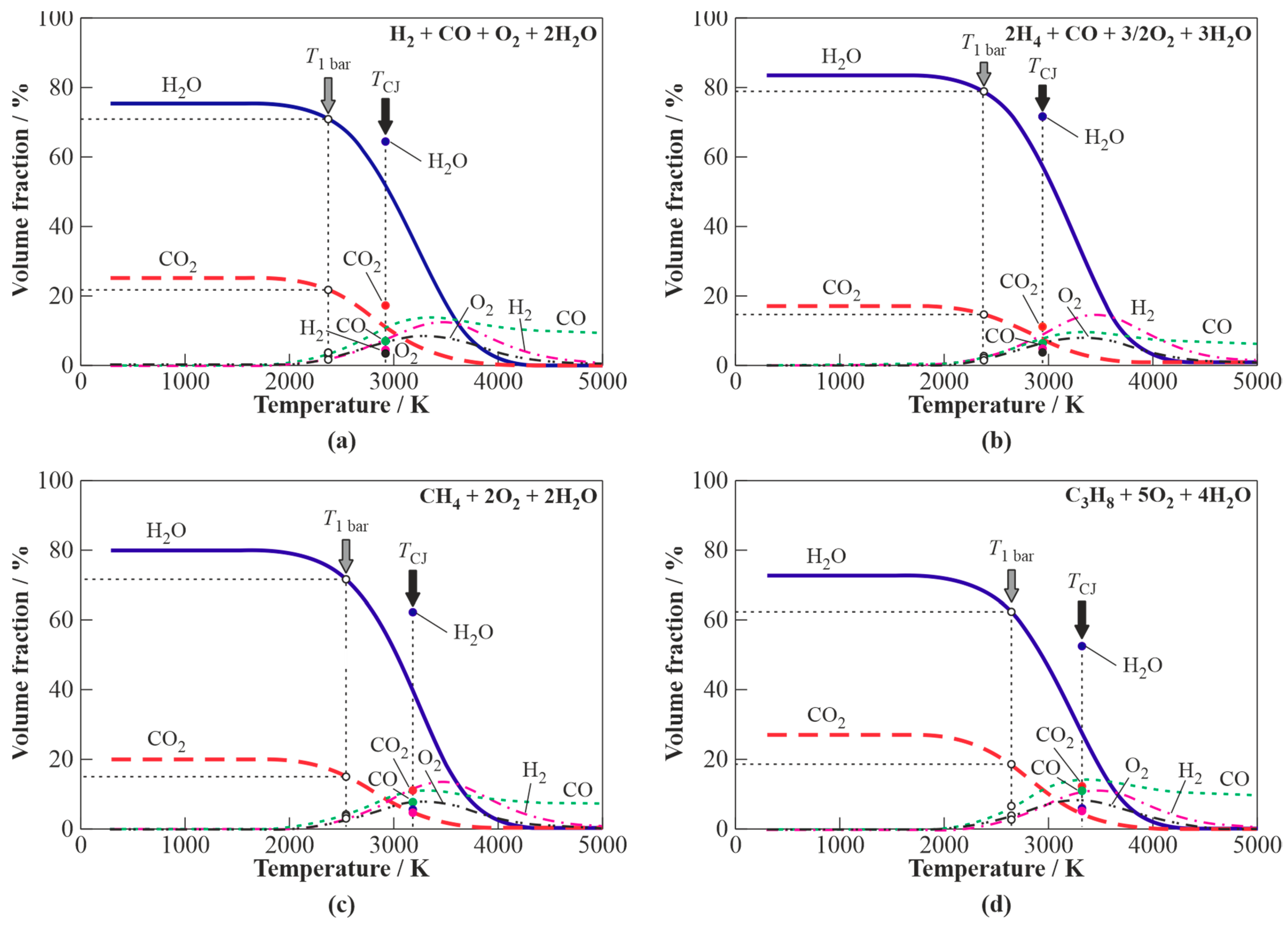
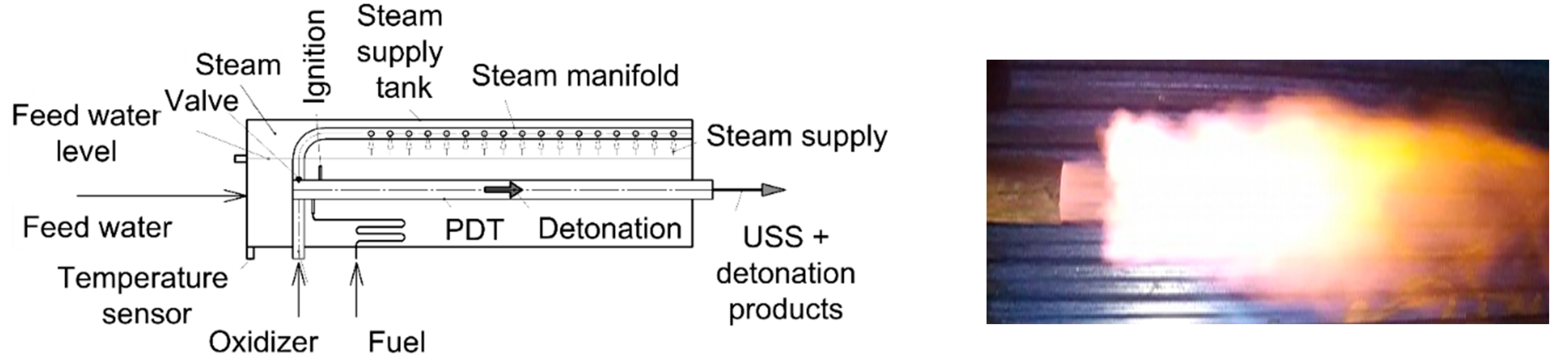
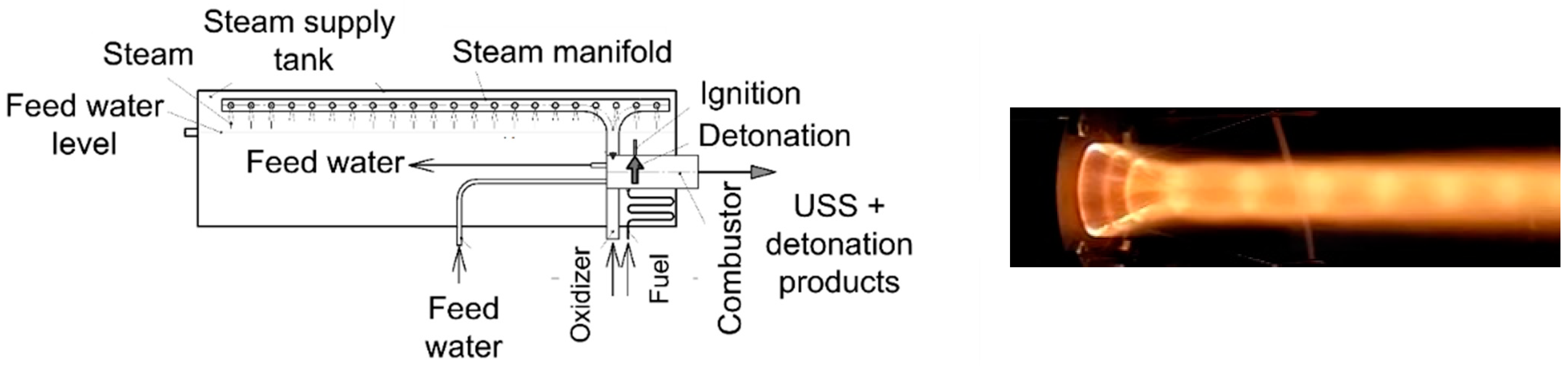
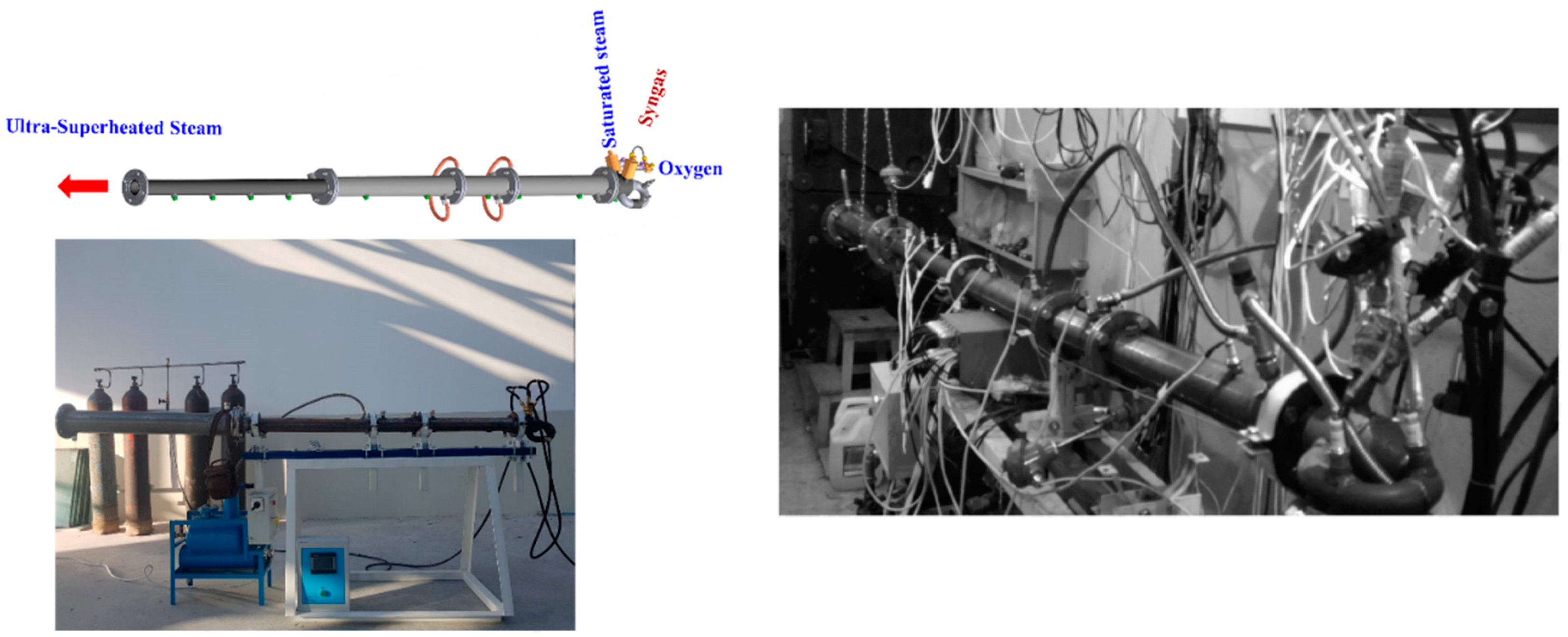
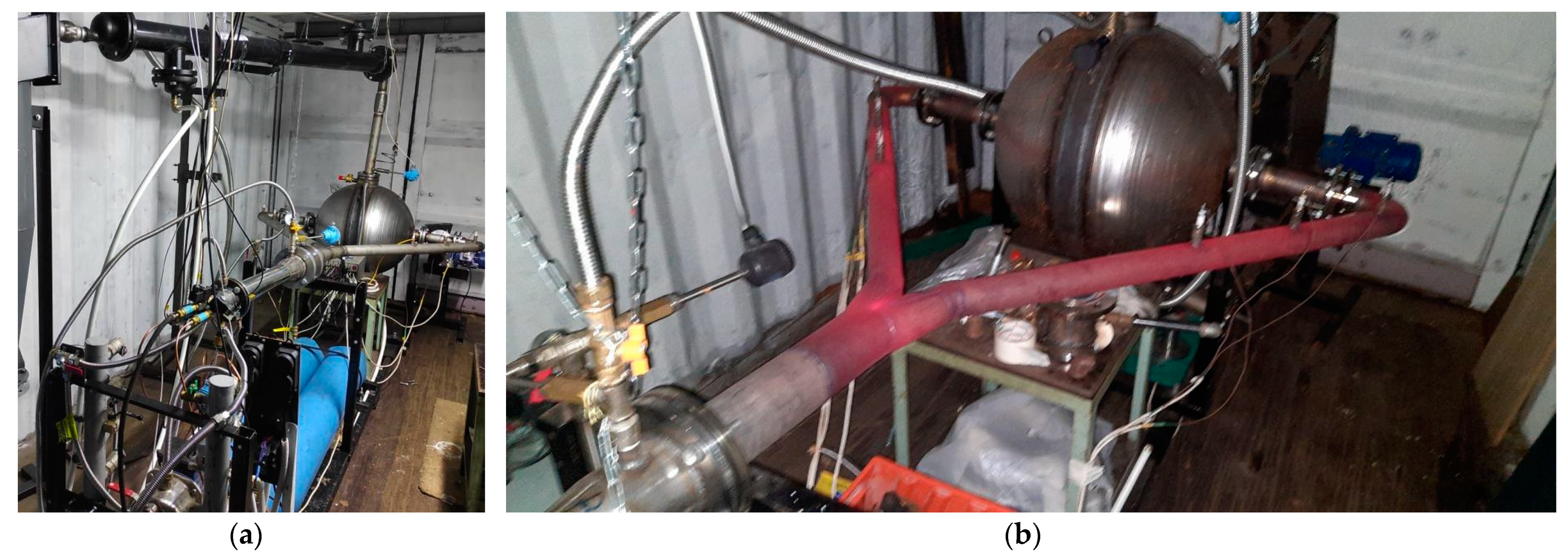
Table 1.
Main heterogeneous and homogeneous reactions during the solid waste gasification process.
| No. | Reaction | Reaction Heat | Reaction Name |
|---|---|---|---|
| 1 | C + 1/2O2 = CO | −111 MJ/kmol | Carbon partial oxidation |
| 2 | CO + 1/2O2 = CO2 | −283 MJ/kmol | Carbon monoxide oxidation |
| 3 | C + O2 = CO2 | −394 MJ/kmol | Carbon oxidation |
| 4 | H2 + 1/2O2 = H2O | −242 MJ/kmol | Hydrogen oxidation |
| 5 | CnHm + n/2O2 = nCO + m/2H2 | Exothermic | CnHm partial oxidation |
| 6 | C + H2O = CO + H2 | +131 MJ/kmol | Water-gas reaction |
| 7 | CO + H2O = CO2 + H2 | −41 MJ/kmol | Water-gas shift reaction |
| 8 | CH4 + H2O = CO + 3H2 | +206 MJ/kmol | Steam methane reforming |
| 9 | CnHm + nH2O = nCO + (n + m/2)H2 | Endothermic | Steam reforming |
| 10 | C + 2H2 = CH4 | −75 MJ/kmol | Hydrogasification |
| 11 | CO + 3H2 = CH4 + H2O | −227 MJ/kmol | Methanation |
| 12 | C + CO2 = 2CO | +172 MJ/kmol | Boudouard reaction |
| 13 | CnHm + nCO2 = 2nCO + m/2H2 | Endothermic | Dry reforming |
| 14 | pCxHy = qCnHm + rH2 | Endothermic | Dehydrogenation |
| 15 | CnHm = nC + m/2H2 | Endothermic | Carbonization |
Table 2.
Some representative experimental studies of low-temperature steam gasification of CCMs at 1 bar.
Table 2.
Some representative experimental studies of low-temperature steam gasification of CCMs at 1 bar.
| Ref. | Reactor | Heating | Gasification (S/F) | Tg, °C | Process Time | Feedstock; (Particle Size; Moisture) | Gas Yield db | H2 (CO2) vol% db | Tar db | Char wt% db | LHV (HHV) MJ/nm3 |
|---|---|---|---|---|---|---|---|---|---|---|---|
| [104] | Rotary kiln 2 rpm/7° | Electr. | H2O + N2 | 850–1050 | G: 2–5 s S: 15 min | RDF | 60–89wt% | 27–65 (4.6–17.6) | No info | 17 | 14.6–17.8 |
| [113] | Rotary kiln 2 rpm/3° | Electr. | 0.8H2O + 0.2N2 (2.1) | 850 | G: 9 min S: 15 min | RDF (2 mm; 25–30wt%); poplar wood (4 mm); scrap tires (2 mm) | 61–90wt% | 43–52 (5–23) | No info | 14–41 | 13.4–25.3 |
| [122] | Updraft fixed bed | Comb. | H2O (2.8–5.4) | 530–930 | G: 1 min 1 | Wood chips (15–20 mm; 19wt%) | 40–52wt% | 37–52 (27–31) | 5.7–9.5% (50–100 g/nm3) | 15–21 | (10–12) |
| [127] | Co-current fixed bed | Electr. | H2O (2–3) | 700–800 | No info | Spruce wood pellets (7wt%) | 0.6–0.7 nm3/kg | 51–64 (8–23) | 60 g/nm3 | 15–20 | 8.4–11.1 |
| [128] | Fixed bed | Electr. | H2O + N2 (0.4–0.8) | 650–850 | 30 min | Meat; bone meal (0.005–3.2 mm; 4.3wt%) | 29–37wt% | 36–49 (13–26) | 52–58 (+H2O) | 13–27 | 17.7 |
| [138] | Rotary kiln | Electr. | H2O + N2 (2) | 850–1000 | G: 5–6 s; S: 100 min | Waste tires (6 mm); | 35–86wt% | 51–65 (3–8) | 5–27wt% | 33–43 | 14.6–25.1 |
| [140] | DFB | Comb. | H2O (2.1–2.3) | 850 | No info | Plastics (PE, PP, PET) | 1.0–2.1 nm3/kg | 34–50 (6–29) | 142–370 g/nm3 | 4–9 | 16.4–27.2 |
1 Estimated; G = gas; S = solid.
Table 3.
Some representative experimental studies of low-temperature CO2 and H2O/CO2 gasification of CCMs at 1 bar.
Table 3.
Some representative experimental studies of low-temperature CO2 and H2O/CO2 gasification of CCMs at 1 bar.
| Ref. | Reactor | Heating | Gasification (CO2/F) | Tg, °C | Process Time | Feedstock; (Particle Size; Moisture) | Gas Yield (CO2 free, wt%) | CO % db | Tar wt% db | Char wt% db | Gas LHV (HHV) |
|---|---|---|---|---|---|---|---|---|---|---|---|
| [158] | Fixed bed | Electr. | CO2 | 300–500 | 2.5 min | Switchgrass (4–9wt%) | 13–36 | 13–43 vol | 24–37 | 33–64 | No info |
| [159] | Tubular | Electr. | CO2, CO2 + N2 | 850 | 13.5 s | beech wood chips (4–5 mm; 10wt%) | 67–72 | 5–5.5 wt | No info | 11 | No info |
| [162] | Fluidized bed; fixed bed | Electr. | CO2 + N2 (0.6−1.6 mb) | 700–934 | 60 min | Pine WS (0.3 mm; 8wt%) | 51–77 | 92 wt | 11–14 | 13–34 | (11.7–12.1 MJ/nm3) |
| [68] | Tubular | Electr. | CO2 + N2 | 100–800 | 60 min | Poplar WS (0.3–0.6 mm; 8.4wt%) | 11–41 | No info | 8–42 | 17–81 | 18–31 MJ/kg |
| [165] | Rotating | Electr. | H2O, CO2, H2O + CO2 | 750 | 120 min | beach wood, bagasse, olive wastes, Miscanthus pellets, straw pellets (6–12wt%) | 60–70 | No info | 10 | 5–26 | No info |
Table 4.
Some representative experimental studies of high-temperature H2O/CO2 gasification of CCMs at 1 bar.
Table 4.
Some representative experimental studies of high-temperature H2O/CO2 gasification of CCMs at 1 bar.
| Ref. | Reactor | Heating | Gasification | Process Temp., °C | Process Time | Feedstock; Particle Size; Moisture | H2; CO (CO2) vol% db | Tar db | Char wt% db | CCE % | LHV MJ/nm3 |
|---|---|---|---|---|---|---|---|---|---|---|---|
| [207] | Drop tube | Electr. | N2; H2O; CO2 | 800–1400 | 4.3 s | beech WS (0.3–0.45 mm; 8.7wt%) | 22–40; 26–40 (6–8) | 0–8wt% | 4–7 | No info | No info |
| [212] | thermal plasma gun | Plasma | H2O + N2 | 500–700 | 4 min | rice straw pellets (10 × 20 mm; 5–55wt%) | 43–51; 43–50 (4–7) | No info | 7.5 | No info | No info |
| [215] | H2O/Ar plasma gun | Plasma | H2O + Ar | 1200–1400 | up to 10 min | WS (10.5wt%); wood pellets (6 mm; 7.4wt%); plastics (1–6 mm); pyrolysis oil | 41–60; 30–52 (3–7) | below 10 g/nm3 | No info | 80–100 | No info |
| [216] | H2O/Ar plasma gun | Plasma | H2O; H2O + CO2 | 1120–1170 | 2–5 min | RDF (25 mm; 4.6wt%) | 37–53; 28–42 (3.5–8.5) | 130–540 mg/nm3 | No info | 82–83 | 10.9 |
| [217] | H2O/Ar plasma gun | Plasma | H2O; H2O + CO2 | 1200–1300 | up to 40 min | WS (7.7wt%); wood pellets (13 × 6 mm; 7wt%); pyrolytic oil (21wt%); RDF; lignite (45wt%); plastics (2–10 mm) | 19–61; 33–54 (2–25) | Below 10 mg/nm3 | No info | 75–95 | 9.4–12.1 |
| [218] | Rotating-arc plasma gun | Plasma | CO2 + Ar | No info | No info | textile dyeing sludge | 28; 49 (0–11) | No info | No info | 93.4–100 | 8.9 |
Publisher’s Note: MDPI stays neutral with regard to jurisdictional claims in published maps and institutional affiliations. |
© 2021 by the author. Licensee MDPI, Basel, Switzerland. This article is an open access article distributed under the terms and conditions of the Creative Commons Attribution (CC BY) license (https://creativecommons.org/licenses/by/4.0/).
Share and Cite
MDPI and ACS Style
Frolov, S.M. Organic Waste Gasification: A Selective Review. Fuels 2021, 2, 556-650. https://doi.org/10.3390/fuels2040033
AMA Style
Frolov SM. Organic Waste Gasification: A Selective Review. Fuels. 2021; 2(4):556-650. https://doi.org/10.3390/fuels2040033
Chicago/Turabian StyleFrolov, Sergey M. 2021. "Organic Waste Gasification: A Selective Review" Fuels 2, no. 4: 556-650. https://doi.org/10.3390/fuels2040033