Review

Towards the Commercialization of Solid Oxide Fuel Cells: Recent Advances in Materials and Integration Strategies

by
Catarina Mendonça
1,
António Ferreira
2,3 and
Diogo M. F. Santos
1,*
1
Center of Physics and Engineering of Advanced Materials (CeFEMA), Instituto Superior Tecnico, Universidade de Lisboa, 1049-001 Lisbon, Portugal
2
Galp Energia, Sines Refinery, 7520-952 Sines, Portugal
3
Faculty of Engineering, University of Porto, Rua Dr. Roberto Frias, 4200-465 Porto, Portugal
*
Author to whom correspondence should be addressed.
Fuels 2021, 2(4), 393-419; https://doi.org/10.3390/fuels2040023
Submission received: 20 August 2021 / Revised: 4 September 2021 / Accepted: 18 September 2021 / Published: 9 October 2021
(This article belongs to the Special Issue Clean and Renewable Hydrogen Fuel)

Abstract

:
The solid oxide fuel cell (SOFC) has become a promising energy conversion technology due to its high efficiency and low environmental impact. Though there are several reviews on the topic of SOFCs, comprehensive reports that simultaneously combine the latest developments in materials and integration strategies are very limited. This paper not only addresses those issues but also discusses the SOFCs working principles, design types, the fuels used, and the required features for electrodes and electrolytes. Furthermore, the implementation of this type of fuel cell on a commercial scale is analyzed. It is concluded that decreasing the SOFCs working temperature can reduce some of its current constraints, which will have a positive impact on SOFCs commercialization. Considering that SOFCs are already being successfully implemented in combined heat and power systems and off-grid power generation, the current status and prospects of this technology are thoroughly discussed.

1. Introduction

The production of power and the associated environmental impacts have become important matters throughout the world. It generally relies on the combustion of fossil fuels, contributing to both global warming and local air pollution. As a result, enormous quantities of sulfur compounds and soot and are produced as well as other noxious emissions [1,2,3]. It is now crucial to develop advanced clean energy systems to switch from a fossil fuel-based economy to a new paradigm known as the hydrogen economy [4].
Research and industry sectors are focusing their attention on fuel cell technologies due to the potential to provide long-term durability clean energy to consumers since they can directly convert the chemical energy of diverse fuels into electricity without combustion. Each fuel cell comprises a cathode and an anode, which are separated by an ion-conducting electrolyte, in addition to other components, such as interconnects and sealants [5]. There are several types of fuel cells, which are generally classified according to the nature of the applied electrolyte. These types include proton exchange membrane fuel cells (PEMFCs), direct methanol fuel cells (DMFCs), alkaline fuel cells (AFCs), molten carbonate fuel cells (MCFCs), phosphoric acid fuel cells (PAFCs), and solid oxide fuel cells (SOFCs) [6].
Sir William Groove, in 1839, proposed the concept of the fuel cell. By using his background in electrolysis, he designed a reverse process that combined hydrogen and oxygen to produce electricity [7]. In 1905, Fritz Haber submitted the first patent on fuel cells with a solid electrolyte, using glass and porcelain as the electrolyte materials and platinum and gold as the electrode materials. Between 1933 and 1959, Francis Thomas Bacon investigated alkaline electrolyte fuel cells, demonstrating the first fully operational fuel cell. Later on, in 1960, NASA used the AFC technology developed by Bacon in its Apollo space program, and in 1990, NASA jet propulsion developed the first direct methanol fuel cell [6,8].
SOFCs present several advantages over other types of fuel cells. These are related to the flexibility in the selection of the fuel, the ability to operate SOFCs directly on practical hydrocarbon fuels, and the higher overall efficiency [9]. The fact that the range of operating temperature is between 600–1000 °C allows SOFCs to use conventional thermal cycles to yield enhanced thermal efficiency and to extract hydrogen from a variety of fuels. This type of fuel cell is tolerant to carbon monoxide (CO), which is electrochemically oxidized to CO2 at the anode in opposition to PEM fuel cells, which are highly sensitive to CO poisoning [9,10,11]. SOFCs also have greater tolerance to impurities in the fuel, such as sulfur (as hydrogen sulfide, H2S, and carbonyl sulfide, COS), and to changes in the fuel composition such that fuel processing conditions are less strict [9,12]. These characteristics allow SOFCs to be supplied with gases obtained from both solid and liquid fuels, becoming an advantage for coal-based central power generation and in vehicles powered by diesel or gasoline fuel [11].
Considering that all the components in a SOFC are solid structures represents an advantage for the cell to be constructed in any geometry. Moreover, since there are no moving parts in the fuel cell except for the Balance of Plant (BoP) components, the noises and vibrations related to mechanical action in the course of operation are nearly non-existent. Thus, this system can be installed in urban or suburban areas as a distributed power generation plant. Without moving parts, the system is expected to have enhanced reliability and lower maintenance costs. The size of a SOFC module is flexible, allowing it to be constructed for use in any power range—from watts to megawatts. Hence, a SOFC or its hybrid can be built for stationary applications (central power generation and distributed power generation) or as an auxiliary power unit (APU) for vehicles [4].
Lastly, the fact that they do not contain any precious metals reduces significantly their cost, and the absence of any liquids in the cell avoids potential problems related to corrosion and loss of electrolyte [11].
Nevertheless, the high operating temperature of SOFCs leads to material issues for each SOFC component, such as the electrolyte sintering problem and the electrode catalyst poisoning, the interfacial problem between each component due to the different coefficients of thermal expansion for the components of each cell [13]. Therefore, a proper fabrication method and an appropriate choice of materials are important factors to consider for each component to prepare single-cell and stacks, especially in microfabrication size for a simple design used in transportation and portable application [14,15]. Moreover, lowering the operating temperature of SOFCs improves the efficiency of fuel consumption, such as CO consumption. It also allows reducing the costs, particularly of the interconnects, manifold, and sealing materials [9,16].
Another challenge SOFCs are facing for some applications is the amount of time necessary to heat up and cool down the system. This effect is associated with the need to use a relatively weak, brittle component as the substrate material and due to constraints related to thermal expansion mismatches. This limits the use of SOFCs in applications that demand rapid temperature oscillations, such as transport applications, where a fast start-up and cool down is crucial [9,16].
This review paper starts by reviewing the general working principle of SOFCs, design types, and the properties of each SOFC component, including electrodes, electrolytes, and interconnects. It also discusses the latest developments and research in each component material to face the challenges stated above. Furthermore, the integration strategies and implementation of this type of fuel cell on a commercial scale are also pointed out.

2. Fundamentals of SOFCs

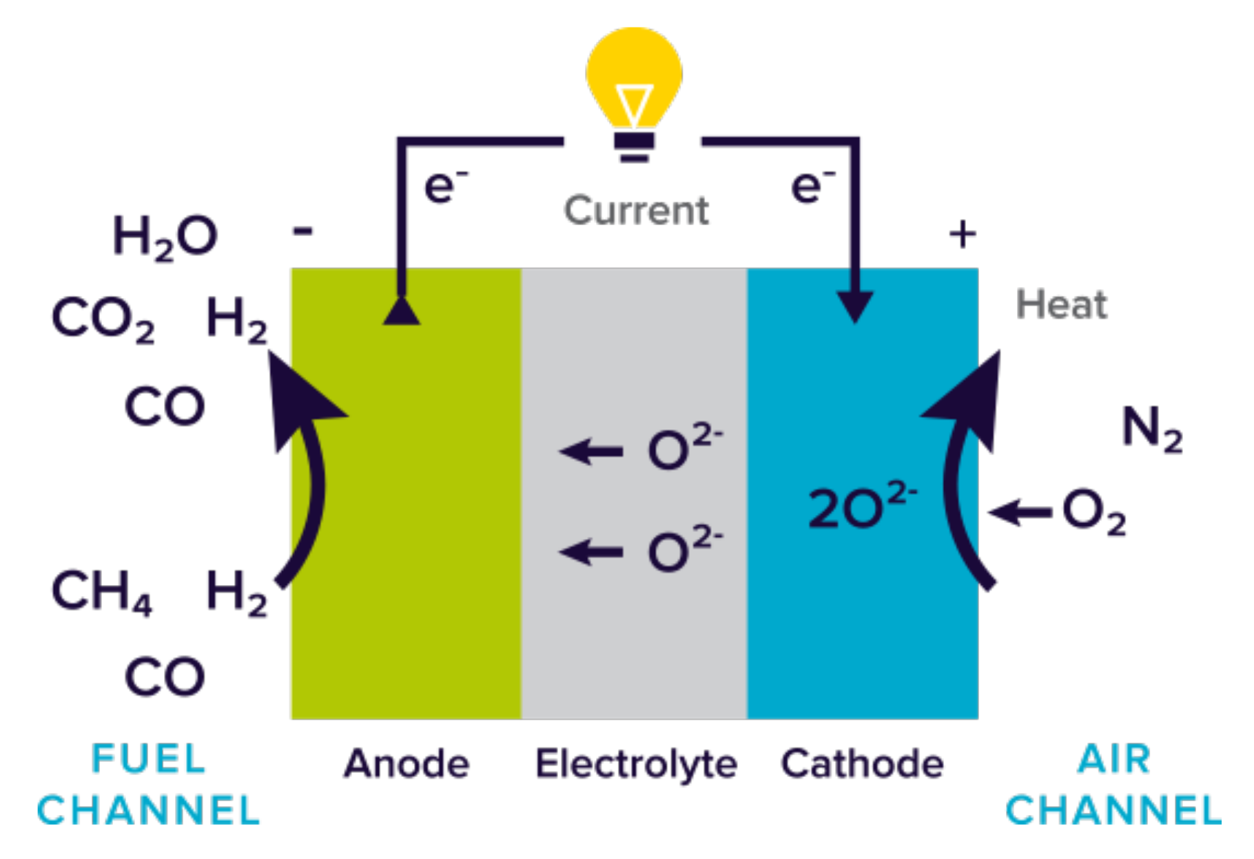
2.1. Working Principles

Fuel cells rely on the transportation processes occurring during electrochemical reactions, where the chemical energy of fuel and oxidant is converted into electric energy, represented by the load through the three main components: anode, electrolyte, and cathode (Figure 1). The most important components of a SOFC are the porous electrodes separated by the dense ceramic electrolyte [6,17].
Hydrogen and CO are fed into the anode of the fuel cell, and oxygen, from the air, enters the cell through the cathode. On the anode side, H2 and CO are oxidized and emit electrons that flow to the cathode through an external circuit. After receiving electrons, O2 undergoes a reduction reaction producing oxygen ions (O2−), which are conducted through the ceramic electrolyte and react with fuel to produce water and carbon dioxide in an exothermic chemical reaction that generates heat additionally [17,18,19].
Figure 1. Schematic diagram of transportation processes in a SOFC based on oxygen-ion conductors. Reprinted from [20] with permission from Convion.
Fuels 02 00023 g001
The main reactions of a SOFC [19,21] depend on the anode feeding by H2 and CO (Equations (1) and (2)), the cathode feeding by O2 (Equation (3)), and the transportation process that was described by Tesfai and Irvine [21].
H 2   +   O 2   H 2 O   +   2 e
CO   +   O 2   CO 2   +   2 e
1 2 O 2   +   2 e     O 2
Reforming natural gas or other hydrocarbon fuels to obtain the required hydrogen can be achieved within the fuel cell, excluding the requirement for an external reformer in contrast to the other types of fuel cells [17].

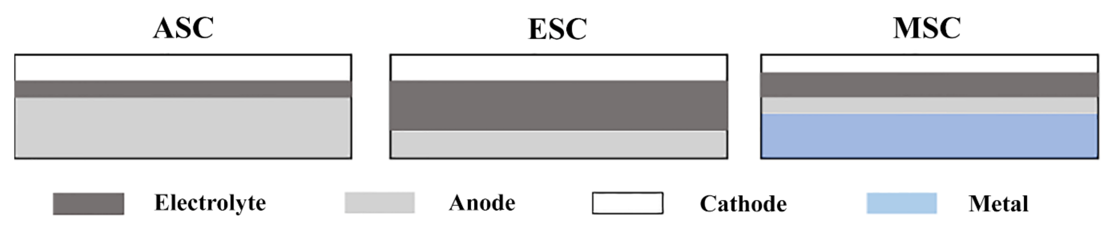
2.2. Cell Design of SOFCs

Nowadays, there are different solid oxide cell designs established (Figure 2). Most common are anode-supported cells (ASC) and electrolyte-supported cells (ESC), but metal-supported cells (MSC) also play a role in the emerging market. The anode-supported cell technology is the most sensitive configuration to RedOx cycling, known as a repetitively coupled reduction and oxidation reactions, often involving oxygen and reactive oxygen species. However, it is also the most common owing to high performance at low temperature thanks to the dense thin electrolyte, while metal-supported cells should be the most stable [22]. Regarding electrolyte-supported cell, it is a robust cell under RedOx conditions; nevertheless, as a consequence of the high ohmic losses in the thick electrolyte at low temperatures (700–800 °C), higher temperatures are required, making the impact of the faster reoxidation imperative [22,23].

2.3. Stack Design of SOFCs

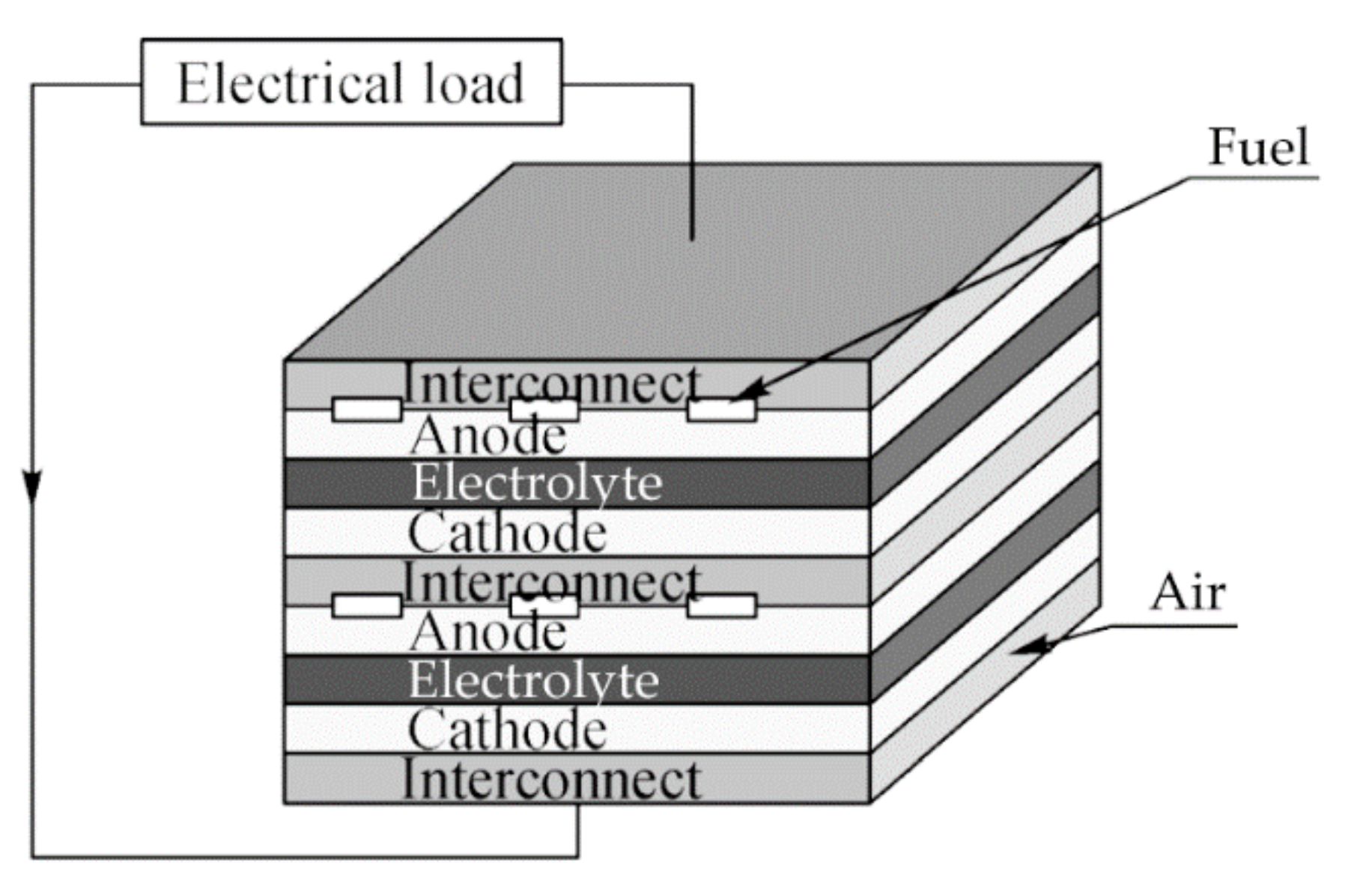
2.3.1. Planar Design

The primary structure of a unit cell comprises two porous layers, anode and cathode, separated by a dense electrolyte layer. In the case of assembling many cells (a stack), an interconnect is necessary (Figure 3), and the sealant, which can prevent the mixing of fuel and air, is another optional component for a planar SOFC [6]. The planar design is the most studied one because it can achieve higher power volume density, and it can be optimized to minimize reoxidation of the anode-supported cell [24].

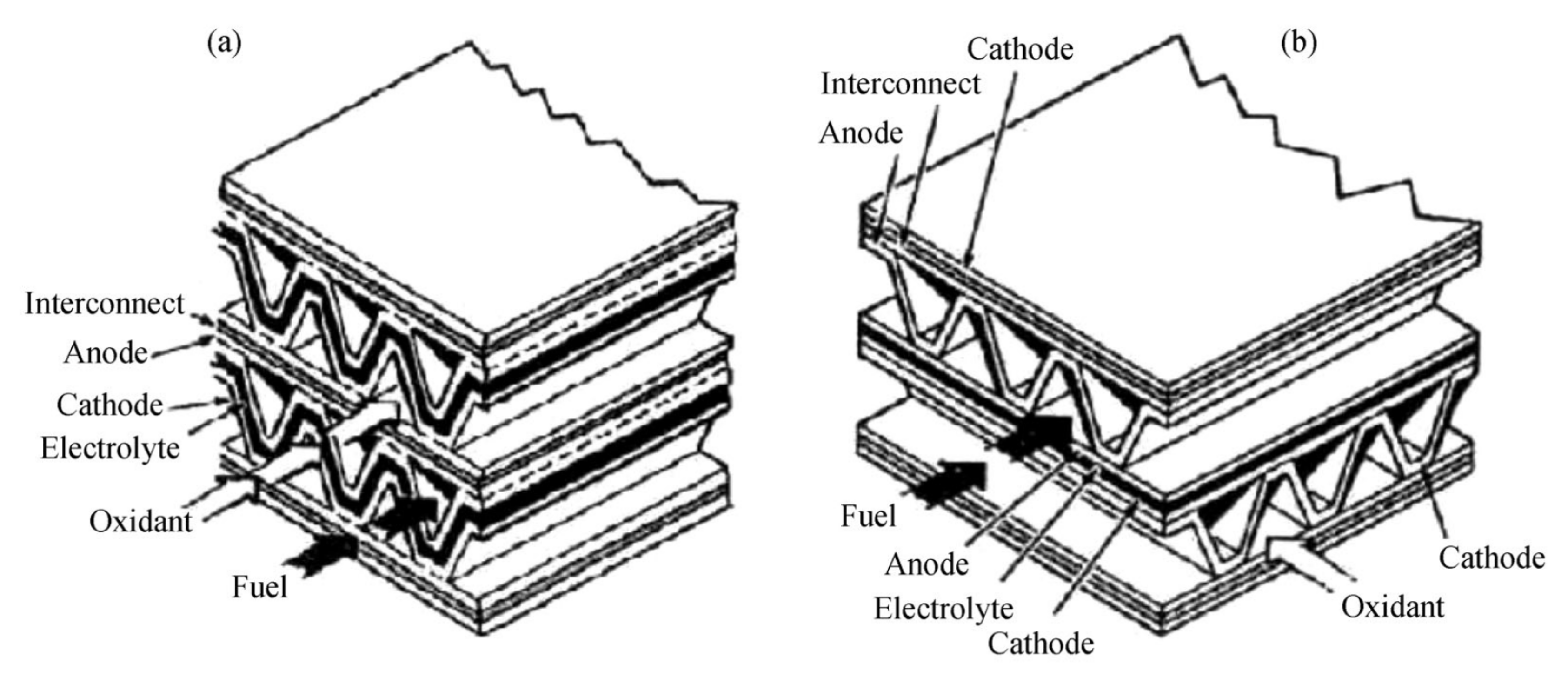
2.3.2. Monolithic Design

This type of SOFC is based on a primary structure design comparable to that of a heat exchanger. Besides the cathode and anode separated by the dense electrolyte, it includes the interconnect and current collectors put together into a channeled structure. Two distinct arrangements for this design are possible: gas co-flow and gas crossflow (Figure 4) [6,24].

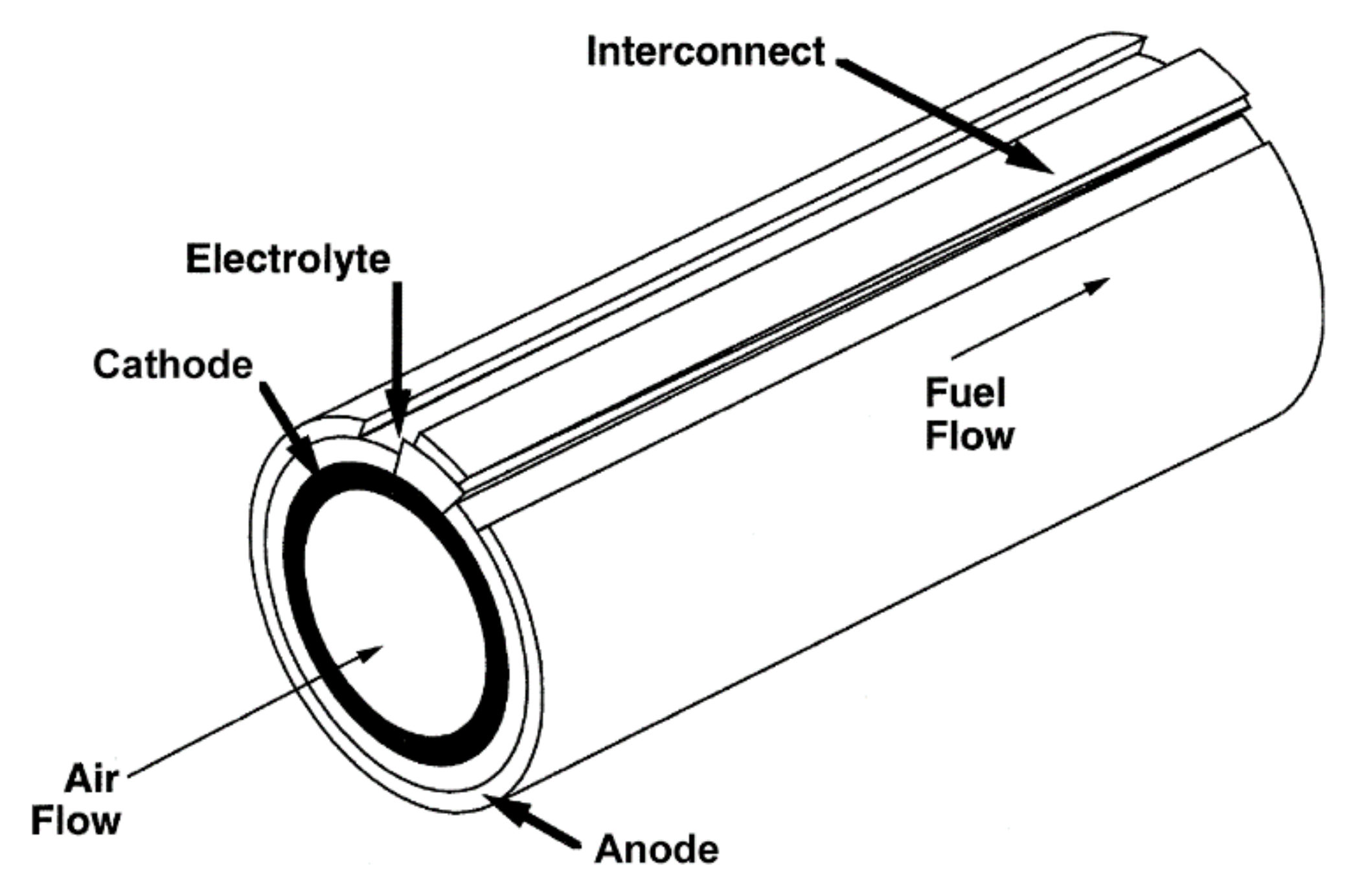
2.3.3. Tubular Design
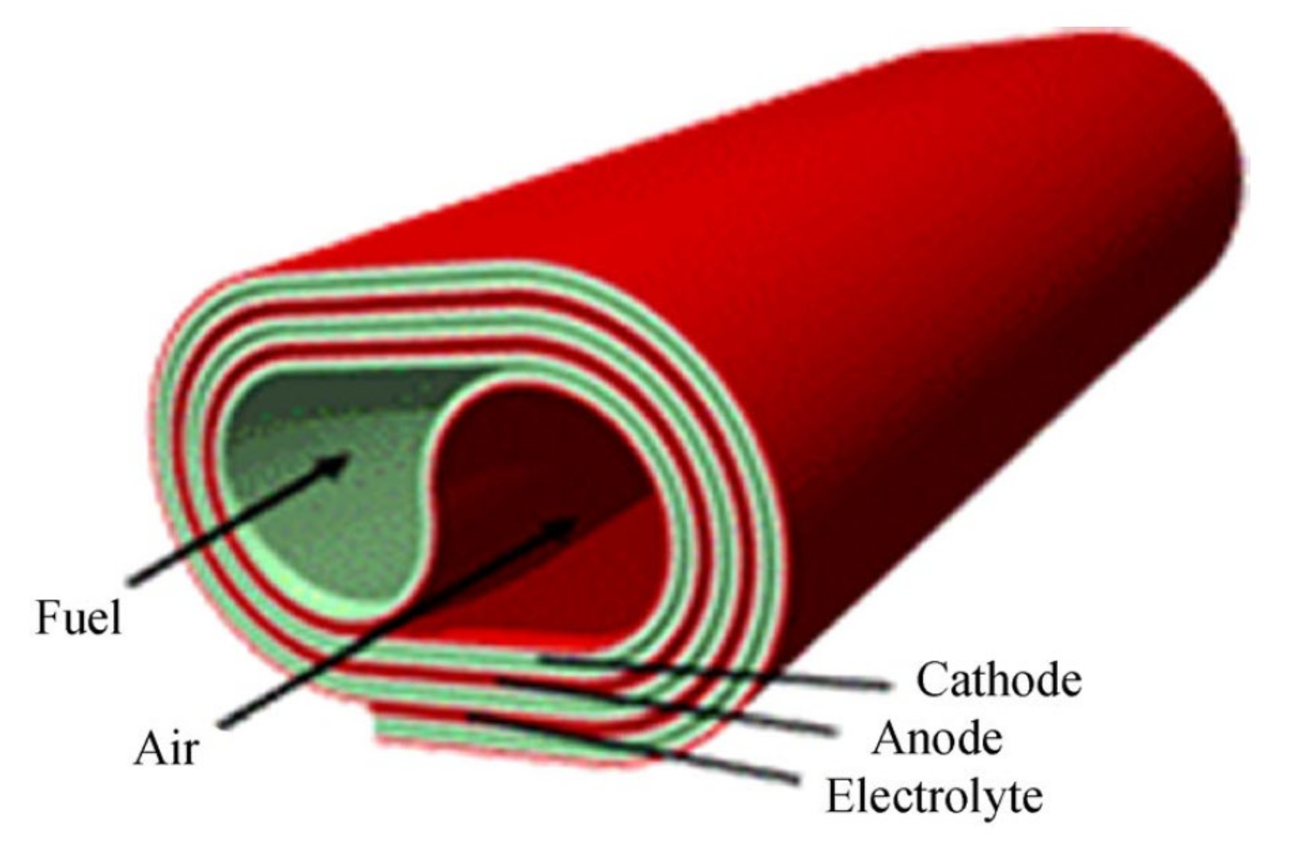
This configuration can be seal-less and comprises a tubular cell with a cathode-coated core, the anode on the outside of the cell, and the electrolyte in between. The oxidant is introduced throughout the inside of the support tube, while the fuel flows at the outside (Figure 5) [6]. Although tubular cells look back on a long history, today, they are relegated to a niche in low-power systems due to the expensive cost of the manufacturing process and the high ohmic losses that reduce the ionic conductivity of the electrolyte [23].

2.3.4. Roll Design

The SOFC configuration in the roll design is prepared using a tape-casting process, with each element of the fuel cell being cast individually as an easily manipulated, flexible tape. The anode, electrolyte, and cathode components are laminated jointly and arranged to give the preferred geometry (Figure 6). Regarding fuel supply, it can be introduced in both anode and cathode (core) through stainless steel tubes [6,26].

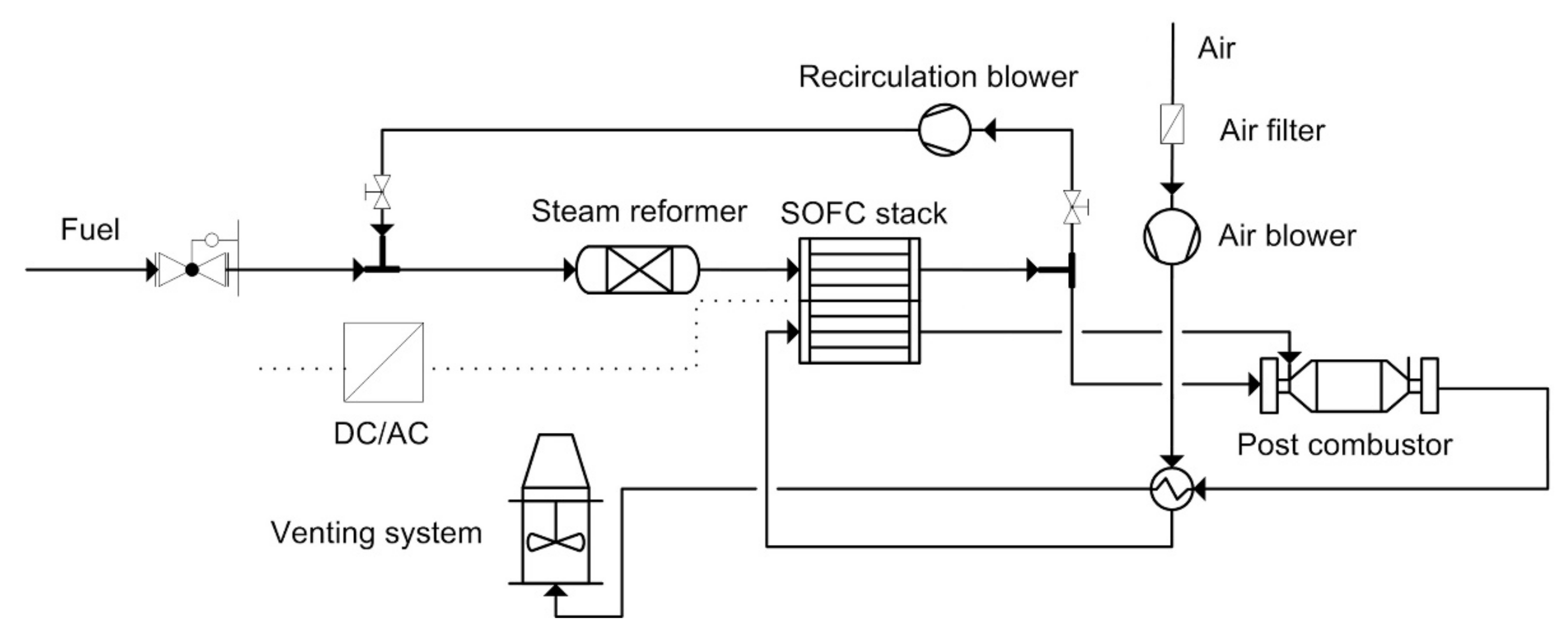
2.4. Fuel Processing in SOFC

A huge variety of fuels, such as natural gas, biogas, gasoline, and kerosene, can be applied in SOFCs adopting four different modes: external reforming, internal reforming, partial oxidation, and direct oxidation. The first three are reforming of fuels, wherein hydrocarbon fuels (e.g., CnH2n+2) are converted into syngas (H2 and CO) through steam reforming, dry/CO2 reforming, catalytic partial oxidation, and oxidative steam reforming or auto-thermal reforming and then electrochemically oxidized on the SOFC anode. The last one of these modes corresponds to the direct oxidation of fuels on the anode [27].
In external reforming, the endothermic steam reforming reaction and the fuel cell reaction are operated distinctly in different units with no direct heat transfer between both unit operations. By opposition, in the case of internal reforming, the steam reforming reaction and the exothermic reaction from the oxidation reaction are operated in a single unit [28].
There are two internal reforming modes: direct and indirect internal reforming. Indirect internal reforming physically divides the reforming process from the electrochemical process, recovering the cell-stack heat release either by radiation heat transfer or by direct physical contact between the cell hardware and the reforming unit. Alternatively, in the direct internal reforming, the hydrocarbon fuel-steam mixture is submitted directly into the anode segment, and the fuel is reformed on the nickel-based anode layer [28].
Endothermic reforming reactions on the anode are a useful way of preserving the temperature uniformity of the SOFC stack concerning exothermic fuel oxidation. This can prevent localized heating, resulting in reduced cell degradation and undesirable built-in thermal stresses within the cell components. However, the efficiency of internal reforming is hindered by sluggish electrode kinetics for low-temperature (LT)-SOFCs. Externally reforming is thus an ideal approach for LT-SOFCs since the external reformer can convert the humidified hydrocarbon fuels into H2-rich/CO-rich reformate gas before reaching the anode compartment, avoiding carbon formation. Furthermore, external reformers are connected to desulfurization units and heat exchangers to prevent sulfur poisoning and to maintain uniform heat distribution throughout SOFC stacks [27].

3. Material Components of SOFCs

3.1. Electrolyte

Electrolyte characteristics have a huge importance on the fuel cell performance due to its contribution to the ohmic internal resistance, which is the material’s opposition to the flow of electric current. An ideal SOFC electrolyte should have a high oxide ion conductivity, low electronic conductivity, low cost, and be environmentally benign. Good thermal and chemical stability towards the reactant environment and the electrode materials and closely matched thermal expansion coefficient (TEC) between electrodes and contacting components are also major features. Additionally, very thin layers can be fabricated, and a fully dense structure will enable to maximize conductivity and minimize reactant crossover. This reduces the internal cell resistance and prevents the mixing of the fuel and oxidant gas feeds [7,28,29].
SOFCs can be classified into three categories according to types of conducting ions: oxygen-ion-conducting SOFCs, proton-conducting SOFCs, and mixed-ion-conducting SOFCs [9]. Due to these different conduction mechanisms, the location of the generated water is different in each one. H2O is generated on the anode in oxygen-ion-conducting SOFCs, however, on the cathode in proton-conducting SOFCs, whereas in the case of mixed-ion-conducting, it is formed on both anode and cathode [19].

3.1.1. Oxygen-Ion-Conducting Electrolyte Materials for SOFCs

The most traditional one is the oxygen-ion transportation mode. Oxygen from the air is reduced to oxygen ions in the cathode, which are transported to the anode through the oxygen vacancy channel by the drive of concentration difference and potential difference [9]. The materials used in the electrolyte are yttria-stabilized zirconia (YSZ) and cerium oxide (CeO2) stabilized by Gd or Sm [30]. This is because, adding to a good oxygen-ion conductivity, they show good stability in both oxidizing and reducing atmospheres and are unreactive towards other components used in the SOFC. They are also abundant, rather low in cost, and strong but easy to fabricate [7].
Yi and Anil produced anode-supported SOFCs with a thin film of YSZ as the electrolyte, and the maximum power density was measured to be 1.7 W cm−2 with hydrogen, 1.3 W cm−2 with CH3OH, and 0.8 W cm−2 with alcohol-water (1:1 in volume) at 800 °C, respectively. The study revealed that Tb-doped YSZ and Ti-doped YSZ could promote the peak power density up to 50% [31]. A range of dopant cations was studied, including Y3+, Eu3+, Gd3+, Yb3+, Er3+, Dy3+, Sc3+, Ca2+, and Mg2+. Scandia-stabilized zirconia (SSZ) gives the highest conductivity, even though Sc2O3 is more costly than Y2O3. Nevertheless, the amount applied in a thin, supported electrolyte is smaller, and therefore, there is much interest in this electrolyte [29].
The sintering temperature can be reduced using a sintering aid, without affecting the high conductivity of the SOFC electrolyte. Pradnyesh et al. reported Fe as an effective sintering aid for YSZ, although the increase in Fe concentration caused a slight decrease in the ionic conductivity [9,31].
Even though YSZ has a lower ionic conductivity than most of the materials being developed for intermediate temperature operation, proper conductance can be reached by producing electrolyte films with a thickness of 10 µm or less. However, the constraint to overcome is to fabricate a homogenous, leak-free layer on a porous substrate by a process that is flexible to volume manufacture [29].
The CeO2-based electrolyte has demonstrated a higher magnitude in oxygen-ion conductivity than conventional YSZ electrolyte, especially at lower temperatures. However, Ce4+ is partially reduced to Ce3+ inside the electrolyte when there is a reducing atmosphere on the anode side, which not only causes the increase in electron conductivity but also causes lattice expansion of the electrolyte. Consequently, this can generate a decrease in the open-circuit voltage of the cell and a decay in the mechanical properties. Challenges related to electronic leakage become prevalent at lower electrolyte thickness and higher temperatures. Owing to these concerns, the performance of SOFCs with CeO2-based electrolyte is quite inferior to the expected based on its conductivity and its improved compatibility with mixed ionic-electronic conductor (MIEC) cathodes [9,32].
The main compensating defect in ceria is oxygen vacancies. Samarium (Sm)- and gadolinium (Gd)-doped ceria were reported to be excellent ionic conductors for intermediate-temperature (IT)-SOFCs (nearly 6–7 times that of YSZ at 600 °C) and outstanding compatibility with high-performance cathode materials, namely cobalt-containing perovskite oxide cathodes [33]. In addition to Gd and Sm, other rare earth cations have been used as dopants in ceria, for example, lanthanum (La) and niobium (Nb) [34,35]. The effect of doping of alkaline earth oxides in ceria, such as CaO, SrO, MgO, and BaO, was studied by Arai et al. They discovered that co-doping of ceria with two or more cations (alkaline earth and rare earth cations) improved the conductivity when compared with single-doped ceria in the air [36,37].
Solovyev et al. prepared and investigated several SOFCs with single-layer YSZ or gadolinia-doped ceria (GDC) and YSZ/GDC bilayer electrolyte, and the outcome showed that single-layer GDC is the most effective electrolyte at lower operating temperatures of 650–700 °C [38]. Considering the comprehensive performance and cost of YSZ, even though it has a low conductivity at low and intermediate temperatures, many researchers are still trying to fabricate a thin film and utilize it in intermediate-temperature fuel cells [9].
Adding to the two materials characterized by fluorite structure stated above, some materials with the ABO3-type perovskite structure have been found to have remarkable chemical stability in both oxidizing and reducing environments, and their ionic conductivity can be dominant over a large range of oxygen partial pressures. Some of the materials of the ABO3-type perovskite structure have oxygen-ion conductivity, whereas others have proton conductivity. As a typical oxygen-ion-conducting electrolyte material for SOFCs, LSGM (La1–xSrxGa1–yMgyO3) revealed excellent performance on ionic conductivity and long-term stability [9].
Perovskite-type phases resulting from lanthanum gallate possess greater ionic conductivity than stabilized zirconia between 500–800 °C. This is due to the substitution of La3+ by alkaline earth elements and/or integrating divalent metal cations, such as Mg2+, into gallium sublattice, which increases the concentration of oxygen vacancies [39]. Decreasing the conductivity has also been observed when a smaller-size cation on the A-site is doped. Introducing a small amount of cations with variable valences, such as cobalt, onto the gallium site, increases the ionic conductivity of LSGM, and consequently, a small increase in the electronic conductivity is reached [40].
Ishihara et al. demonstrated that LSMG displays high ionic conductivity (comparable to that of GDC) and low electronic conductivity even at reduced partial oxygen-pressure levels. This class of materials offers suitable performance at temperatures as low as 400 °C [41] and have therefore been pointed out as possible candidates for low- and intermediate-temperature SOFCs [42]. Optimized compositions exhibit ionic conductivities near 0.14 Scm−1 at 800 °C [40,42].
Nevertheless, LSGM is correlated with many inherent downsides, such as the expensive cost of the material, poor sinterability, and loss of Ga oxide throughout the sintering process when submitted to high temperatures. Some of these problems have been solved by additional B-site replacement and process optimization. Interesting performance has been observed from electrolyte-supported and thick-film cells that have been manufactured using the optimized powders. Nevertheless, the production of anode-supported cells with LSGM electrolyte by co-firing process seems to be challenging owing to the significant reaction between LSGM and the traditionally used anode catalyst Ni at high temperatures; the latter results in the formation of LaNiO3 phase, which is an ionic insulator [32,38].
Amongst oxide ion-conducting materials, oxide phases obtained from Bi2O3 are particularly interesting owing to their high ionic conductivity compared to other solid electrolytes. This superior ionic conductivity is afforded due to a combination of high anion mobility and a high concentration of oxygen vacancies (around 25%) [3]. Bi2O3 presents a considerable polymorphism with two stable phases, α and δ. High conductivity appears in the high-temperature δ-phase of a fluorite-type structure. The δ-phase is only stable above 730 °C [39]. The stabilization of the δ-Bi2O3 phase down to temperatures of 700 and 800 °C can be accomplished if bismuth is replaced with rare-earth dopants, such as Y, Dy, or Er, and their combinations with higher valence cations, such as V, W, or Nb [39]. The addition of Bi2O3 in SSZ leads to improved ionic conductivity. The highest conductivity was observed in bismuth-oxide-doped 10ScSSZ (10 mol.% Sc2O3) [43].
The main problem with Bi2O3-based electrolytes for fuel cell application is their instability in the reducing atmosphere since they decompose into bismuth metal under anode conditions. Although Bi2O3-based electrolytes are stable in the air atmosphere, their low melting point causes their decomposition at temperatures above 800 °C. These features make Bi2O3 a weak choice by itself as an electrolyte for SOFCs, and there is no reference in the literature, in anode- or electrolyte-supported configuration, wherein Bi2O3-based electrolytes are independently used. Studies on these electrolytes are reduced to low-temperature conductivity measurements [33].

3.1.2. Proton-Conducting Electrolyte Materials for SOFCs

In the proton transportation mode, the hydrogen ions resulting from the oxidation reaction of hydrogen molecules that occurred in the anode are transferred to the cathode through the interface transfer based on the proposed “swing model”. The proton-conducting material is an essential functional material with protons as charge carriers for the small diameter, lightweight, and reasonably high mobility of the particle. Amongst all the proton conductors as electrolytes for SOFCs, the BaCeO3-based electrolytes display the highest proton conductivity [9].
Ito et al. set a 0.7 μm thick BaCe0.8Y0.2O3 thin electrolyte film on the Pd substrate and assembled a single cell that reached peak power densities of 900 and 1500 mW cm−2 at 400 and 600 °C, respectively. Nonetheless, Pd is not appropriate for commercialization due to its high cost [44]. Peng et al. produced a 50 μm thick BaCe0.8Y0.2O3 film on Ni substrate, leading to a peak power density of 340 mW cm−2 at 700 °C, 10 times higher than that obtained with proton-conducting SOFCs with thicker electrolyte films [45].
BaCeO3-based electrolytes are characterized by weak resistance to carbon dioxide and water corrosion, leading to lower proton conductivity, which leads to thermal expansion of the materials and critically reduces the performance of SOFCs. Otherwise, BaCeO3-based electrolytes show multi-type ions-conducting properties above 600 °C, which hinders the research on the material. Another possible option as electrolyte material is BaZrO3, which presents reasonably high stability in water or carbon dioxide atmosphere and improved chemical and mechanical strength [9]. However, large-scale application is restricted due to its high grain-boundary resistance and high sintering temperature. Improved proton conductivity is reached by reducing the grain-boundary density for doped BaZrO3. For example, sintering at 1600 °C yields relatively large, 1 μm-sized grains. The highest proton conductivity for doped BaZrO3 was obtained via pulsed laser deposition of BaZr0.8Y0.2O3−δ (BZY20) onto a (100)-oriented MgO single-crystal substrate [46]. By reaching an outstanding crystallinity and removing grain boundaries that block proton transport in the doped BaZrO3 electrolyte, a proton conductivity of 0.01 S cm−1 at 350 °C was observed [47].

3.1.3. Mixed-Ion-Conducting Electrolyte Materials for SOFCs

Mixed-ion-conducting electrolytes result from the introduction of different types of electrolytes. These composite electrolytes allow for simultaneous diffusion of both oxygen ions and protons, extensively increasing the ionic conductivity. Usually, they comprise ceria-based carbonate composite electrolyte and ceria-based tungstate complex electrolyte, among others. It is stated that the total ionic conductivity of the composite material is higher than the total of each raw material. This means that the behavior of the composite material changes and stimulates the ionic conduction mechanism, enhancing the ionic conductivity. The composite electrolyte consists of two or more materials with distinct charge conduction characteristics, mostly including oxides and salts. These composite materials possess a high capability of conducting charges, and the ionic conductivity can reach 0.01–1 S·cm−1 at 400–600 °C, which is significantly higher than the achieved from typical single-phase electrolyte materials [9].
Benamira et al. studied composite materials based on GDC and alkali carbonates (LiCO3–K2CO3 or Li2CO3–Na2CO3) and measured the stability of such composites over 6000 h [48].
Wu et al. examined the stability of conductivity of LSGM-30 wt.% (Li/Na)2-CO3 composite electrolyte. The results revealed that the conduction of oxygen anions, hydrogen cations, and carbonate anions inside the LSGM-(Li/Na)2CO3 composite electrolyte occurs simultaneously, and the main reason is the conduction of carbonate anions at elevated temperature [49].

3.1.4. Fabrication Methods for Electrolytes

To produce an intermediate temperature SOFC with relatively high performance, bi-layering can be an interesting approach. Bi-layered systems take into account two electrolyte layers to overcome the disadvantages associated with the single electrolyte layer. This type of strategy can lead to a synergistic effect to surpass the individual drawbacks and improve power performance for a prolonged period. Even though bi-layering looks interesting in principle, it also faces challenges, such as shrinkage compatibility, TEC compatibility, and possible interdiffusion between two components, which should be addressed [33].
It is of major importance to produce electrolytes as thin as possible to minimize ohmic losses in situations where the ionic conductivity at low temperatures is not sufficiently high. A wide range of techniques to produce thin films has been discussed. The most commonly used are atomic layer deposition, chemical vapor deposition, physical vapor deposition, pulsed laser deposition, atmospheric plasma spraying, and sol-gel [3].

3.2. Interconnect

The interconnect (referred also as bipolar plate) in planar fuel cells has the vital role of separating the oxidant and the reducing fuel atmosphere, collecting the current from the electrodes, conducting the electrical current between adjacent cells, distributing reactant gas evenly across the face of each electrode, and offering mechanical support to the cell and stack structure [50].
The component must have a high electronic conductivity in both oxidizing and reducing atmospheres, low contact resistance with the electrodes, good thermal conductivity (effective removal of heat from the electrodes is crucial in maintaining an even temperature distribution), must not react with any of the other components at the high operating temperatures, have suitable chemical and thermal stability; very low permeability to reactant gases, good mechanical strength, corrosion resistance, impermeability, thin and lightweight construction, easy manufacturability, and low cost [7,29]. Moreover, other vital factors must be analyzed when interconnecting materials are chosen, including oxygen kinetics and electrical properties.
The only proper material for interconnects in high-temperature SOFCs was alkaline-earth-doped LaCrO3 or other Cr-containing perovskites [51]. Nonetheless, with the progress in high-performance, anode-supported SOFCs, the operating temperature of a SOFC was significantly reduced to the range where high-temperature metallic alloys are adequate for use and present considerable advantages over ceramic LaCrO3-based ones. These are related to lower cost, the fact that they are genuinely electronic conductors and oxide ion insulators, and fabrication is trustworthy when compared to ceramic ones. Furthermore, thermal stability is effective, in particular with the planar SOFC design where a metallic interconnect is normally used as the mechanical support of a thin assembly of each component in the fuel cell [52,53].
One of the potential alloys that are considered to replace LaCrO3 as interconnect material for SOFCs is the Cr-based oxide-dispersed strengthened alloy, Cr-5Fe-Y2O3, known as Ducrolloy [54]. Its operating temperature is close to 1000 °C and exhibits excellent oxidation resistance along with a TEC that matches other adjacent SOFC materials. Nevertheless, one of the disadvantages of Ducrolloy is that excess Cr2O3-scales cause inadequately high area-specific resistance after oxidation at 1000 °C for 75 h. Additionally, the current inaccessibility of a simplified fabrication process and high processing costs make this alloy unsuitable for application [5].
Fe-Cr-based alloys show greater ductility, lower cost, and better practical applicability than Cr-based alloys. Ferritic stainless steel, a type of Fe-Cr-based alloy, when doped with optimum Cr-content (17–25%), forms continuous Cr2O3-scales, which renders excellent oxidation resistance and is considered the alloy with the most potential due to its economic feasibility and good TEC matching the other SOFC components [55,56,57].

3.3. Anode

The anode performs the electrooxidation of the fuel by catalyzing the reaction and facilitating fuel access and product removal [29,58]. To fulfill these demands, the anode material should be chemically compatible, thermally stable, highly (ionic, electronic) conductive, with a highly porous and organized structure, and fine particle size [6].
Since the fuel reaching the SOFC anode is usually reducing in nature, metals can be applied as the anode material. Nevertheless, the elevated working temperatures of SOFCs effectively limit the choice to cobalt, nickel, and noble metals. The vast majority of SOFCs have a nickel anode due to its low cost when compared to the other options [7].
As mentioned, the anode should have a porous structure, which must be preserved at high operating temperatures. This is accomplished by dispersing nickel with the solid electrolyte material to form a cermet (a composite of ceramic and metal), which keeps the porosity by avoiding sintering of the nickel particles throughout the operation and also provides the anode with a TEC similar to that of the solid electrolyte [7]. Moreover, this microstructure is optimized to have a fully percolated metallic component that allows conduction of electrons through the structure, while optimizing the amount of active triple-phase boundary (TPB), known as the interface at which the electronic and ionic conducting phases co-exist with the open pore containing fuel and where the reaction occurs in most cermets [29].
As it has been widely discussed, reducing the operating temperature continues to be one of the biggest obstacles towards SOFCs commercialization, as it also reduces the electrode materials’ catalytic activity and the ionic conductivity of the electrolyte [5]. Hence, the latest studies to address this problem and improve the anode performance are discussed, dividing the anode materials into two groups: nickel-based cermet and perovskite-based anodes [3].

3.3.1. Ni-Based Cermet

A high anode performance at low temperatures can be reached by introducing an anode functional layer (AFL). The interfacial resistance of the anode-supported SOFCs usually prevails at the intermediate temperature range. Given that the quality of the anode highly affects the cell performance, the AFL layer is usually characterized by a fine-grain structure (to favor increasing TPB length). This is where the anode electrochemical reactions occur to suppress the activation polarization of the anode. The adjacent anode-support structure offers mechanical support for the fuel cell (for an anode-supported cell) and a low-resistance gas-diffusion pathway for the anode fuel and the reaction products. Moreover, the finer porosity of the AFL layer allows for simple electrolyte deposition via colloidal coating methods [59]. Wang et al. produced continuous-graded AFL via an electrophoretic co-deposition route and observed an increase in the TPB length and the consequent expansion of the area for electrochemical reactions on the anode [60]. Hyun and coworkers recently developed NiO-YSZ nanocomposite materials for AFL which showed high performance in Ni-YSZ-based cells [3,61].
The traditional, sponge-like, porous electrode does not favor gas diffusion given its high tortuosity factor that subsequently reduces the performance of SOFC. Finger-like channels in the anode and cathode have been demonstrated experimentally to promote gas transport. Chen et al. observed that the molar fraction gradients of H2, CO, CH4, and CO significantly decrease by the finger-like channels in the anode compared to one without such channels [62].
Although Ni-based cermets have been commonly implemented as anodes in SOFCs, owing to their simple production and high catalytic activity of Ni for hydrogen oxidation, they reveal some drawbacks. These include a low tolerance to the sulfur that exists naturally in fuels; to carbon, except if a considerable amount of steam is added to reform the fuel; and nickel coarsening along with inferior volume stability upon redox cycling [3,63].

3.3.2. Perovskite Oxides

Most of the functional perovskite oxides in SOFC exhibit simultaneously high oxygen ionic and electronic conductivities. This property is typical of MIECs. These MIEC perovskites have been studied as alternative ceramic anode materials. They present much larger areas of TPBs, leading to a better anodic performance relative to its electronic- or ionic-conducting perovskite counterpart. MIEC perovskite oxide is an appealing next-generation SOFC anode component since it has active sites that promote the activation of C-H bonds for hydrocarbon oxidation, which can be enhanced by adjusting the concentration of oxygen vacancies and their mobility to mitigate the carbon coking [64]. Among those, Sr2MgMoO6−δ (SMMO), (La0.75Sr0.25)0.9Cr0.5Mn0.5O3 (LSCM), Pr0.4Sr0.6Co0.2Fe0.7Nb0.1O3−δ (P-PSCFN), and PrBaMn2O5+δ (PBM) showed potential as anodes for SOFCs operated on hydrocarbon fuels [3].
Chromite-based single perovskites
The strontium-doped lanthanum chromite (LSCr) single perovskites have been a focus of study and characterization as SOFC anode materials over the past decade. Cr is known to have strong hexagonal coordination with oxygen deficiency [65]. Thus, the introduction of cations with lower coordination numbers (e.g., Mn, Co, Fe, and Ni) can enhance the catalytic activities of LSCr [66]. The presence of these cations in the B-site provides the possibility to create oxygen vacancies in reducing atmospheres at high temperatures, leading to improved LSCr anode electrical conductivity. LSCrM is one of the most known perovskites that displays high-temperature stability and good resistance to carbon deposits. It also shows redox stability when fueled under oxidizing and reducing environments, which allows its application as electrodes in symmetrical SOFC (SSOFC). Though, LSCr-based perovskites have rather low electrical conductivity in reducing atmosphere, therefore showing weaker electrochemical-reaction kinetics than Ni-YSZ [64].
To enhance catalytic activities and improve the electrical conductivity of these LSCr-based single perovskites, four main directions have been pursued [64]:
  • Producing composite with redox-active transition metals, such as Cu and Ni;
  • Changing the chemical composition of conventional LSCr-based anode;
  • Doping A-site or/and B-site with different metal cations; and
  • Mixing other electrical conductors or exsoluted nanoparticles from doped LSCr to create a composite anode.
Lanthanum-doped SrTiO3
Lanthanum strontium titanate (LST) is a notorious anode candidate between perovskite materials. It has very high electronic conductivity, high methane oxidation catalytic activity, and acceptable thermal and chemical stability under SOFC anode atmosphere even in the presence of H2S [67]. Nevertheless, its relatively low catalytic activity for the fuel-oxidation reactions conducted to low maximum power densities for LST anode-based single cell, making it unfeasible for industrial applications [3,28].
Double perovskites
Double perovskite anodes have been studied because of their exceptional electrochemical properties and the ability to resist carbon formation and sulfur poisoning [68,69]. SMMO has drawn considerable interest given its MIEC properties, high power density in H2/CH4 fuels, and long-term stability when supplied with H2S. However, some studies showed that SMMO displays low oxygen-vacancy concentration along with low catalytic activity and electrical conductivity and detrimental performance degradations under H2S concentration higher than 140 ppm. The structural features of double perovskite offer flexibility via doping route to enhance the SMMO properties [64]. Frequent doping approaches are as follows [70,71]:
  • Partial substitution of La, Sm, and Ba for Sr;
  • Mg substitution with transition metal elements, such as Mn, Fe, Co, Ni, Ti, and Cr; and
  • Mo substitution with V and Nb.
Ruddlesden–Popper-type layered perovskites
Ruddlesden–Popper layered perovskites (with K2NiF4 structure) have received much attention as potential SOFC anodes [72]. This mostly owes to their capacity to hold a great amount of interstitial oxygen, thus leading to fast surface-exchange kinetics, increased oxygen-vacancy concentrations, and reasonably low TECs [73].
However, among the K2NiF4-type layered perovskites, only LaSrMnO4 (LSMO4) and LaSrFeO4−δ (LSFO4), and their derivatives have been stated as redox-stable anode materials. Jin et al. reported La0.6Sr1.4MnO4 as a standalone anode that showed outstanding chemical stability in reducing atmospheres and medium catalytic activity for hydrogen and methane [72]. Composite anodes involving K2NiF4-type oxide (Sr,La)FeO4 and CoFe alloy nanoparticles were obtained by reducing La0.6Sr0.4Co0.2Fe0.8O3−δ (LSCF) [74]. Yet, its improved catalytic activity and electrical conductivity are mostly attributed to CoFe alloy nanoparticles [75].
Even though perovskite anodes seem a promising option, as they are usually stable in anode operating conditions and present high sulfur and coking tolerance under different fuels’ conditions, their catalytic activity, electrical conductivity, and power density are still significantly lower than those for the typical Ni-YSZ anode [3].

3.4. Cathode

Cathodes in SOFCs have multiple roles within the cell: reduction of molecular oxygen, transport of charged species to the electrolyte, and supply of electrical current for the oxygen-reduction reaction (ORR) [29]. Thus, the material used in SOFCs as cathode should [6,7,76,77]:
  • Be highly electronic conductive;
  • Be chemically compatible and thermally stable;
  • The microstructure should be in high percentages of porosity;
  • Give a high catalytic activity for the ORR;
  • Should not show any tendency to react with the electrolyte; and
  • Be easy to process and reliable cost manufacturing.
Additionally, the elevated operating temperatures also play a crucial role by limiting the choice of electrode materials to noble metals or oxides with sufficiently high electronic conductivity. As noble metals are excluded for economic reasons, oxides are exclusively used [7]. Perovskite materials with lanthanum manganite composition doped with rare earth elements, such as Co, Ce, or Sr, are commonly utilized [76,77,78,79]. They provide a good matching in terms of thermo-mechanical performance with the electrolyte, and additionally, these materials are MIECs. Strontium-doped lanthanum manganite (La1−xSrxMnO3, LSM), is the most utilized cathode material for zirconia-based SOFCs.
LaMnO3 is a perovskite material with intrinsic p-type conductivity, the oxygen stoichiometry of which at high temperature is a function of the oxygen partial pressure, having an oxygen excess in oxidizing environment but becoming oxygen deficient in reducing atmosphere. This results from the formation of cation vacancies, and hence, the conductivity can be enhanced using a lower valence ion as a dopant for either the A or B sites, which can be stated through the formula ABO3. A-site cations consist of alkaline or rare earth metal elements, such as La, Sr, or Ba, while B-site cations are 3d, 4d, or 5d transition metal elements, such as Mn, Fe, and/or Co. Moreover, LaMnO3 is usually manufactured with lanthanum deficiency to avoid the formation of La2O3, which can lead the cathode layer to collapse through hydration to La(OH)3 [80,81,82].
Regarding the concern on lowering the temperature of cell operation to the intermediate range, there are considerable difficulties in the materials selection process. They arise because key processes in the cathode, like the reduction of oxygen and its incorporation and transport to the electrolyte, mean that LSM will no longer be effective enough. To enhance cathode performance at low temperatures, different approaches, such as doping, multiphase/composite cathodes, and nanostructured cathode fabrication by infiltration techniques or in-situ exsolution, have been investigated [3,29].

3.4.1. Cathodes on Oxygen-Ion-Conducting Electrolyte

Perovskites
Perovskite-type MIECs have been applied both in IT- and LT-SOFCs to increase the active sites to the whole surface of the cathode. Cobalt-containing perovskite oxides, namely Ba1−xSrxCoyFe1−yO3−δ (BSCF), La1−xSrxCoO3−δ (LSC), La1−xSrxCo1−yFeyO3−δ (LSCF), and Sm1−xSrxCoO3−δ (SSC), are of particular importance. These oxides have MIEC and ORR activity related to Co(III)/Co(IV) transition [83]. However, their large-scale application raises some doubts, as the flexible Co(III)/Co(IV) redox behavior displays multiple technical concerns, such as low chemical stability, high TEC, and high reactivity with zirconium-based electrolyte [84]. Besides, cobalt is a costly additive. Strontium in these MIEC cathodes also leads to performance degradation. This is due to the inactive strontium species that tend to diffuse out (or segregate) to the surface, consequently interfering in the ORR and/or reacting with gaseous species to generate detrimental products, including Sr(OH)2, SrCO3, SrCrO4, and SrSO4 [3].
Nb5+ doping on the B-site of SC (SrNb0.1Co0.9O3−δ) was investigated by Zhou et al. This material was demonstrated to possess simultaneously high oxygen-vacancy concentration and electrical conductivity between 400 and 600 °C [85]. A perovskite doped with Ca, NBSCaCO (NdBa0.5Sr0.25Ca0.25Co2O5+δ), was proposed by Yao et al. as a potential candidate for SOFC cathode application purposes. They observed an improved performance related to electrical conductivity and electrochemical output varying from 690 S cm−1 to 1023 S cm−1 for the temperature range of 30–800 °C, well above the desired conductivity of 100 S cm−1 for the application of SOFC cathodes [86]. Wiff et al. reported that the addition of CeO2 to La0.8Sr0.2MnO3 (LSM) increased substantially the thermal stability of LSM and enhanced the cell performance. It was also noticed that SrFeO3-δ-based perovskites have a lower TEC and better chemical compatibility to YSZ and ceria-based electrolytes compared to SrCoO3−δ-based ones [87].
Double perovskites
Double-perovskite cathodes have also been studied due to their faster rate of surface oxygen exchange and diffusion, higher electrical conductivity, and superior electrochemical performance than single-perovskite cathode materials [88].
He et al. verified that Sn-doped Sr2Fe1.5Mo0.5−xSnxO6-δ (x = 0, 0.1, 0.3, and 0.5) lead to low average formation energy and the increase in the oxygen-vacancies concentration, which enhances the ORR performance, namely the surface exchange and bulk diffusion processes [88]. Layered perovskites are a type of double perovskites that have the structural formula AA′B2O5+δ. A is typically Y or a 3+ lanthanide ion, A′ is usually Ba or Sr, and B is normally a first-row transition metal ion or a mixture of them. Doping LnBaCo2O5+δ with metal components has shown some interesting effects [3]. Substituting Pr by Gd, for instance, reduced the electrical conductivity, the concentration of oxygen vacancies, and the cathode performance. Nonetheless, the opposite tendency was noticed when Sr substituted Ba [89]. Transition metal ions, such as Fe, Cu, and Ni, were introduced into the B-site. When Fe substituted Co, the electronic conductivity and the TEC decreased, while the oxygen ion diffusivity, ORR activity, and stability increased. This indicates that the properties of LnBaCo2O5+δ can be adjusted via appropriate doping [3].

3.4.2. Cathodes on Proton-Ion-Conducting Electrolyte

Recent work suggests the application of BaZr0.1Co0.4Fe0.4Y0.1O3 as a triple-conducting cathode on BZCYYb proton-conducting electrolyte [90]. The high content of Co and Fe (transition metals) in this material is the reason for its high catalytic activity and electronic conductivity. Y doping also enhanced the concentration of oxygen vacancies, creating its triple-conducting function. A layered structure, triple-conducting LiNi0.8C0.2O2 (LNCO) was developed by Fan and Su [91]. LNCO includes intrinsic oxygen ion and electron conductivity and extrinsic proton conductivity, providing its suitability as an H-SOFC cathode material. It also displays high ORR activity with reasonably low activation energy and water uptake property, which all suggest a favorable cathodic reaction activity [3].

3.4.3. Composite Cathodes

Composite cathodes have been extensively investigated to increase the cathodic performance by introducing a second phase into the electrode matrix to produce composite electrodes. Because of this second phase, the electrochemical reaction zone of ORR expands and minimizes the thermal and mechanical incompatibility between electrode and electrolyte. Nd0.5Sr0.5Fe0.8Cu0.2O3−δ-Sm0.2Ce0.8O1.9 composite cathode with 40 wt.% Sm0.2Ce0.8O1.9 component displayed stable performance for 370 h at 700 °C without any substantial variation in the polarization resistance performance. Moreover, La0.4Ba0.6Fe0.8Zn0.2O3−δ-Ce0.8Sm0.2O1.9 exhibited notorious stability upon exposure to 1 vol.% of CO2 in the air at 550 °C for 100 h [88].

4. SOFC Applications

As mentioned above, SOFCs are one of the most efficient and environmental-friendly technologies available for power generation. Not only can they be integrated with traditional electrical power plants but also provide electricity as on-site power generators [92]. There are three main applications of SOFCs related to this field: combined cycle power plant, cogeneration/trigeneration, and residential applications. SOFC are still not quite suitable for portable applications and transportation, as mentioned before, due to their high operating temperature, which leads to long start-up and cool-down times [28].

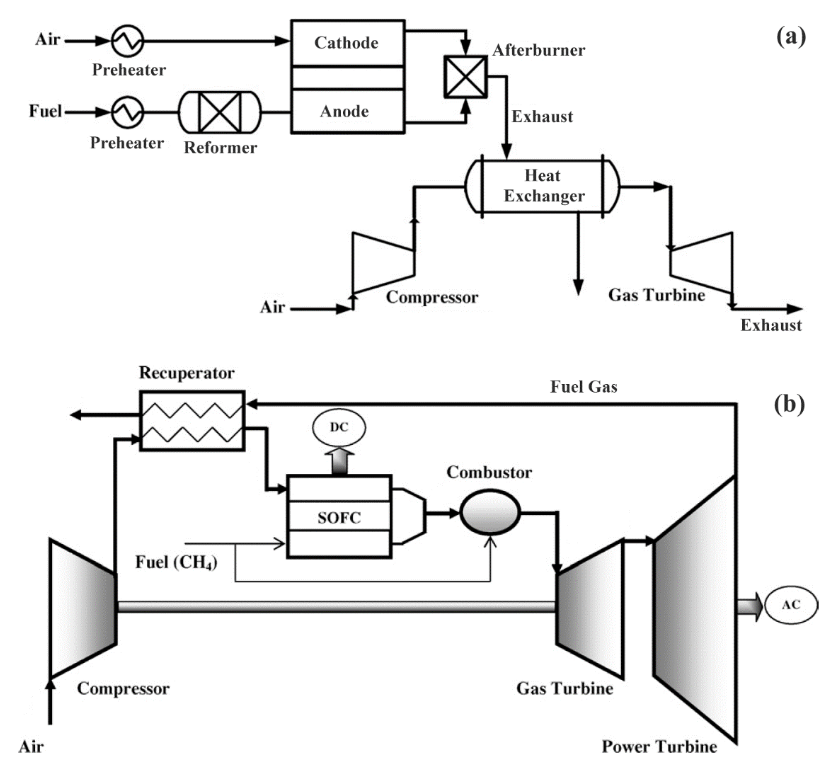
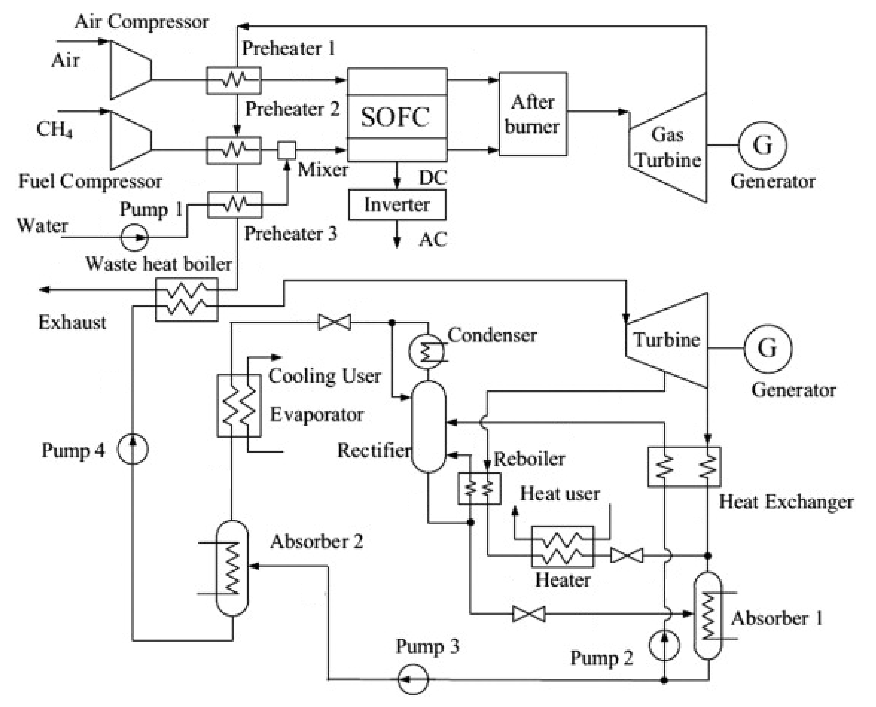
4.1. Combined Gas Turbine (GT) Power System with SOFC

One of the main concerns regarding a conventional GT plant is associated with thermal efficiency since it has considerable losses related to the high irreversibility inside the combustion chamber. This can be improved if direct contact between air and fuel is prevented, as it occurs in fuel cells. A fuel cell–GT hybrid system has a higher energy conversion efficiency, low environmental pollution, and possible use of renewable energy sources as fuel. Although the thermal efficiency depends upon the cycle configuration and layout of the hybrid system, such as a pressurized SOFC–GT combined cycle or a recuperated GT integrated with SOFC, an efficiency until 60% can be reached using the integrated cycle [28].
A GT–SOFC system consists of six elements: air compressor, recuperator, high-temperature SOFC, combustor, gas turbine, and power turbine. There are two different ways for gas turbines to be connected with SOFCs, by indirect or direct integration (Figure 7).
In the indirect SOFC–GT hybrid system, the combustor of the gas turbine is substituted with a heat exchanger in which air from the compressor is heated by the fuel cell exhaust (thermal energy). This type of integration system lowers the sealant prerequisite in the SOFC stack, although the heat exchanger must run at very high temperatures and pressure differences. Thus, the material conditions in the indirect integration of SOFC–GT are a constraint, and for this reason, it is not generally used [4,28].
In contrast, in the direct SOFC–GT hybrid system, pressurized air from the compressor is preheated by the exhaust gas from the power turbine before entering the cathode side of the SOFC, while fuel flows into the anode side. The outlet air from the cathode is utilized to burn the residual hydrogen, carbon dioxide, and methane in the anode outlet gas. The products of the chemical reaction are very lean; thus, supplying a fuel injection into the combustion chamber stabilizes the combustion. The resulting fuel gas is expanded in the turbine and preheats the compressor outlet air in the heat exchanger [28].
It was observed that when SOFC–GT model was analyzed under standard operating conditions, increasing the turbine inlet temperature (TIT) would reduce the thermal efficiency of the plant and exergy efficiency; however, it improved the specific power output of the cycle. Additionally, a rise in the TIT or the compression ratio conducts to a higher rate of exergy destruction of the plant [94,95].
One disadvantage related to SOFC–GT system is the start-up time, which is much longer than in a GT conventional plant. Furthermore, in this system, SOFC stacks need to be pressurized in an extremely large vessel. This practical constraint is reduced in hybrid SOFC-Steam Turbine (ST) systems since stacks operate under atmospheric pressure [96].

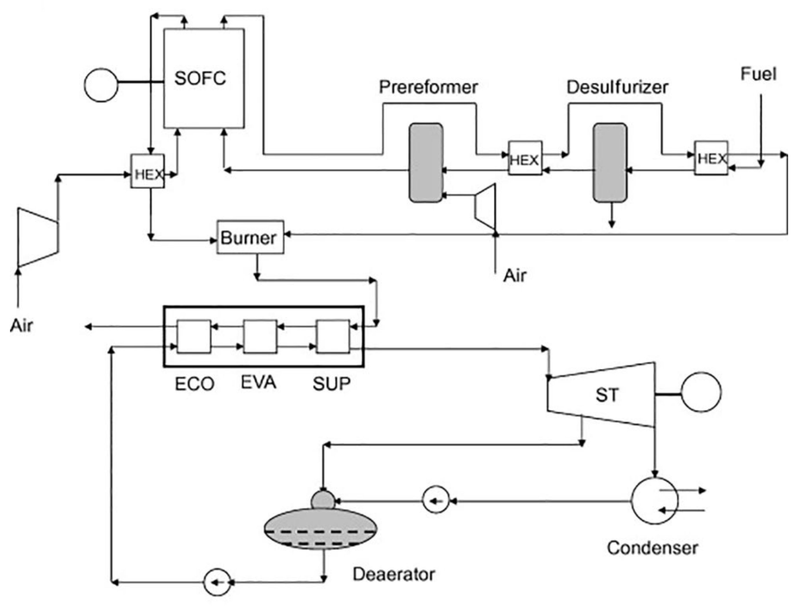
4.2. SOFC Integrated with Rankine Cycle

If the operating temperature of SOFC stacks is reduced to an intermediate value, then the combination of SOFC–ST hybrid systems would be more appealing than the SOFC–GT systems. Not only the material cost for the SOFC stacks is decreased, but also many problems associated with the BoP components are diminished [28].
The scheme represented in Figure 8 consists of a hybrid system with a SOFC on top of an ST [97]. A desulfurization reactor and prereformer are fitted in the plant. The sulfur contained in the fuel is removed in a desulfurization reactor, whereas the prereformer is responsible for breaking down heavier hydrocarbons. The pretreated fuel is then fed to the anode compartment of the SOFC. The remaining fuels enter the burner, with steam being produced by the resulting exhaust gases in a heat-recovery steam generator through a Rankine cycle. This system can achieve a cycle efficiency of up to 67% [96].
The prereforming step can be executed using catalytic partial oxidation (CPO) or adiabatic steam reformer (ASR). The efficiency of this hybrid system depends on the type of prereforming process used, which was found to be higher in a system with ASR type than CPO type. Nevertheless, the ASR reactor needs superheated steam during startup, which can be a disadvantage [96].
The electrical efficiency is increased if the SOFC fuel-utilization factor is decreased. However, this parameter is limited to certain values; otherwise, the TIT would increase and consequently reduce the efficiency of the plant. Thus, changing the configuration of the system has a positive effect on the efficiency of the SOFC–ST combined cycle [28].

4.3. Combined Heat and Power with SOFC

The heat rejected to the surrounding water or air in the conversion process is one of the major sources of loss owing to the intrinsic limitations of the different thermodynamic cycles used in power generation.
Combined heat and power (CHP), or cogeneration, is identified as the sequential generation of two different forms of useful energy, usually mechanical and thermal energy, from a single primary energy source. The high-temperature exhaust gas of SOFCs can be employed for heating purposes, such as in preheaters and reformers, to preheat the air before entering the combustion chamber or to produce steam in a Rankine cycle, as discussed above [28]. Figure 9 represents a Micro-CHP system, mainly used for residential and small business applications in the range of up to 50 kW [98].
Chan et al. investigated SOFC power systems supplied by two different fuels: hydrogen and methane. The hydrogen-fed SOFC system consisted of two preheaters, a SOFC stack and an afterburner where the unreacted fuel from SOFC was burnt, and the heat generated was provided to the reformer, vaporizer, and preheater. In contrast, the methane-fed SOFC system was somewhat more complex. It comprised a mixer, a vaporizer, two preheaters, an external reformer, a SOFC stack, and an afterburner. By comparing the two systems, the use of methane as fuel can provide higher efficiency than using pure hydrogen [97].
Fontell et al. analyzed a 250 kW SOFC plant fed by natural gas that integrated a desulfurization unit to remove the sulfur content in the fuel. The exhaust gas from the anode side of SOFC is used to preheat the reformed fuel and then divides into two parts: one part is burned in the afterburner with the air from the cathode side; the other part is recirculated and mixed with the inlet fuel stream before being fed to the prereformer. The off-gases from the afterburner are employed to vaporize the water stream and preheating the natural gas feed stream. The system’s efficiency can reach up to 85% [99].
Additionally, an integrated SOFC absorption heating and cooling system used for buildings was examined by Zink et al. The analysis showed that such a system could produce electric power, heating, and/or cooling for buildings with the total system efficiency reaching up to 87% [100].

4.4. Trigeneration with SOFC

Trigeneration, defined as combined cooling, heating, and power (CCHP), is currently a promising technology for efficient and clean energy production. It uses in the best way possible the chemical energy of the fuel to generate electricity and heat from the exhaust. Simultaneously, cooling can be generated from absorption or desiccant cooling, consequently reducing the use of electricity in a traditional air conditioning unit (Figure 10) [28].
An energy analysis of a trigeneration system based on a SOFC and an organic Rankine cycle was conducted by Al-Sulaiman et al. [101]. The system also comprised a heating process and a single-effect absorption chiller. It was verified that trigeneration increased efficiency by at least 22% compared to a power plant. They also concluded that when trigeneration was applied, the exergy efficiency increased by 3–25% [102]. Weber et al. carried out detailed CO2 emission and cost analyses of a trigeneration system based on a SOFC primary mover in an office building and found that CO2 emissions were decreased by 30% at a cost growth of 70% compared with a conventional system [103].
The results of a detailed analysis of the trigeneration system show that increasing fuel-flow rate can improve global efficiency but reduce SOFC and electrical efficiency. Alternatively, by increasing the compressor pressure ratio, the SOFC electrical and overall efficiency increases.

5. Commercialization

5.1. History

One of the first pioneers in SOFC commercialization was Siemens Westinghouse PC (SWPC). In the early 2000s, SWPC intended to demonstrate at least 10 SOFC systems of multiple sizes. Some were established but only operated for a short time, and others were canceled before being installed. These comprised 250 kW atmospheric CHP systems, 1 MW pressurized SOFC/GT hybrid systems, and 125 kW CHP systems [104].

5.1.1. 250 kW Atmospheric CHP System

In October 2001, SWPC agreed with BP to install a 250 kW CHP system at BP’s gas-to-liquids (GTL) test plant in Nikiski, Alaska. The system used natural gas as its fuel and was expected to begin operating in 2003. BP’s interest was to consume 150 kW of the unit’s output to power the warehouse and administration building of the GTL facility. As the BP GTL plant was shut down in 2004, the fuel cell demonstration site was switched to Chugach Electric, Anchorage, and modified to accommodate a 125 kW CHP system. In the fall of 2005, Chugach backed out of the project [104].

5.1.2. 1 MW SOFC/GT Hybrid System

EnBW and Siemens Power Generation, in April 2007, declared that they would form a partnership to build a 1 MW pressurized SOFC/GT hybrid demonstration plant at EnBW, Baden-Wurttemberg, Germany, which would be completed in 2008. The project aimed to develop a system with ca. 70% conversion of the fuel energy into electricity. The companies predicted that the proposed plant would ultimately produce up to 2.5 MW of power, sufficient to power about 2500 homes. However, it did not succeed [104].

5.1.3. 125 kW CHP System

In November 2005, SWPC and Meidensha decided to cooperate in developing, manufacturing, and marketing SWPC SOFC systems in Japan. In this order, a 125 kW CHP system was announced to be operated at Meidensha (Tokyo, Japan) in January 2008. After successful completion of the test, the two companies would establish a joint venture, and Meidensha would begin marketing the systems. Nonetheless, both plans were not pursued [104].
In summary, the tubular SOFC technology of SWPC was not technically feasible nor commercially viable. One of the major constraints of the SOFC system was related to the demonstrated lifetime of 16,400 h, being less than half the requisite of 40,000 h. Moreover, the manufacturing of the tubular SOFCs and their assembly was complex and labor intensive, making it extremely expensive and not suited for low-cost mass production processes. Lastly, tubular SOFC systems had intrinsic constraints in attaining high power density. This was due to the long electrical path across the tubes and the large voids within the stack, causing significant ohmic losses, which resulted in a large system with lower power output [104].

5.2. Latest Projects and Developments

There has been a huge effort from companies and governments to improve SOFC technology to achieve its full commercialization and mass production. The latest accomplishments on this matter are discussed, and the technical and performance data of each SOFC’s company are compared in Table 1.

5.2.1. Kyocera

Kyocera is a Japanese company that started developing miniaturized SOFC technologies in 1985. In 2011, the company began mass production of SOFC cell stacks and reached further miniaturization with its third-generation product, achieving ca. 90,000 h of continuous operation, 360 operation cycles (operated at 700 °C in hydrogen/air conditions), and a power output of 700 W. These SOFCs are finding application both in households and in small businesses, such as restaurants and convenience stores [105].
In 2017, Kyocera Corporation announced the first 3 kW SOFC for institutional cogeneration using 700-W cell stacks. The system uses Kyocera’s ceramic technologies and city gas as fuel to provide 52% generation efficiency and overall efficiency of 90% with exhaust-heat recovery. Besides effectively generating energy, exhaust heat from the power generation process can be used to heat water. Lastly, when compared with conventional cogeneration systems, this system provides significant energy savings and lower CO2 emissions, and it can adjust the power generation in proportion to demand [106].

5.2.2. Elcogen

Elcogen was founded in 2001 in Estonia and is considered a manufacturer and developer of high-performance anode-supported IT-SOFC and SOFC. Elcogen’s stacks operating temperature is 650 °C, allowing longer lifetimes, primary energy-conversion efficiency to electricity of 74%, and the use of materials of lower cost both at the cell, stack, and system level. Their stacks are used in various applications, such as residential to micro-CHP in a power range of 1–5 kW; standalone or boiler integrated industrial premium power and CHP in a power range of 20 kW to some MW; APU units for transportation in a power range of 1–5 kW; high-temperature electrolysis for wind and solar energy storage; and power to gas/liquids solutions [107].
Elcogen’s anode-supported SOFCs were applied in a system to generate electricity by feeding it with biogas from a shrimp farm placed in Ben Tre, Vietnam, in 2017. Biomass, such as coconut pomace, rice straw, and bagasse together with concentrated sludge, was supplied to a digester to produce biogas, which was employed as the fuel to produce 1 kW of green electricity with a SOFC system having double the efficiency of conventional heat-engine systems. The green electricity obtained from the local biomass resources was applied for shrimp culture, such as for aeration to the shrimp pond, to validate “carbon-neutral energy circulation” [108,109].
Elcogen partnered up with fuel cell system developer Convion from 2017 to 2019 to produce two CHP systems with a power output of 116 kW, creating a low carbon and energy self-sufficient business district. Convion’s fuel cell systems employ Elcogen’s SOFC and stack technology to provide 60% of electrical efficiency and total efficiency of 80% by waste-heat recovery. As a result, using only low-carbon technologies, the project provided CHP to nearly 50 businesses. Furthermore, the grid was also powered by a 4 MW solar photovoltaic array, an 8 MW biogas engine, and a battery to guarantee a regular power supply [108,110].
Elcogen also announced in April of 2020 a commercialization contract with Magnex CO, a Japanese SOFC stack and system designer, to reach mass production and commercialization of SOFC products. Magnex CO is employing the low operating-temperature technology of Elcogen, taking advantage of low-cost materials and a cost-efficient system design to develop a 1 kW SOFC cell stack, 250-W SOFC portable system, and 1–5 kW SOFC CHP generation system fed by biogas/ethanol. In three years, Magnex plans to sell over 3000 units of its SOFC products going along with the SOFC cell demand of 5 MW. Starting from 2021/22, Elcogen is targeting to mass manufacture roughly 2 million cells per year, taking into account a capacity of 50 MW [111].

5.2.3. Sunfire

Sunfire is a German company founded in 2010 that develops and produces high-temperature electrolyzers and high-temperature fuel cells based on solid oxide cell technology. Sunfire-Remote fuel cell power generators stand for off-grid power generation for industrial and governmental applications, with an average electrical output between 350 to 850 W or multiples in parallel operation. The units are based on SOFCs that operate at temperatures between 800 and 900 °C and are perfectly suited for a reliable, durable, and independent energy supply far away from the power grid. Using propane or natural gas, they achieved electrical efficiencies of up to 35%. Overall efficiencies of up to 90% can be reached by utilizing heat optionally. Sunfire-Remote units are installed at natural gas pipelines in Russia. They have been integrated with solutions for cathodic corrosion protection, remote gate-valve operation, integrity monitoring, and communication along pipelines [112].

5.2.4. Bloom Energy

Bloom Energy was founded in 2001 by Professor K.R. Sridhar, who had been working for NASA on the development of an electrolyzer powered by a solar panel to produce fuel and oxygen that would help support life on Mars [113]. Bloom Energy products are mainly stacks of planar electrolyte-supported fuel cells fabricated with metals sprayed on ceramic supports. Their SOFC systems possess currently up to 65% (LHV) net electrical efficiencies. The company focused on improving continuously the size of their systems in the last years, presently developing the “Energy Server 5”, with an electrical power output of 200–300 kW and the possibility of being combined to form a wider system owing to its modularity. These servers comprise 1 kW electricity stacks, coined as “Bloom Boxes”, which consist of 40 cells of 25 W electricity each, fed with natural gas or biogas [114].
Bloom Energy had a huge impact on SOFC commercialization when it sold, in 2018, 80.9 MW of SOFC systems, which can be compared to a total market of ca. 91 MW [114]. In the USA, it has provided fuel cell power-generation systems for a considerable number of Walmart stores and several size units for companies, such as Apple, AT&T, IKEA, Equinix, Disney Pixar Animation Studios, Maxim Integrated, and Morgan Stanley [115].

5.2.5. Mitsubishi Power

In 2016, Mitsubishi Hitachi Power Systems, Ltd. (MHPS) began testing a pressurized hybrid power-generation system integrating a SOFC stack and a micro gas turbine (MGT). The demonstration system was in the range of 250 kW and delivered a generation efficiency of 55%, with the capability of using various fuels, including natural gas, biogas, and hydrogen [116].
In 2018, MHPS got its first request for a pressurized hybrid power-generation system to be installed in the Marunouchi Building in Tokyo, held by Mitsubishi Estate Co., Ltd. (Tokyo, Japan). This hybrid system was fueled with city gas, generating electricity with both ceramic SOFC stacks, which operated at approximately 900 °C, and MGTs. Since it is used in a CHP system, exhaust heat can be recovered as steam or hot water, improving the combined efficiency. This hybrid system can decrease CO2 emissions by nearly 47% compared to conventional power generation systems, supporting the goal of a low-carbon society [117].
Additionally, in 2019 MHPS received an order from Hazama Ando Corporation to implement their hybrid system in Megamie. This is being applied as a distributed power-supply system to support the “Hazama Ando Next-Generation Energy Project”, a program designed to reduce CO2 emissions. Hazama Ando seeks to shift to hydrogen fuel with zero CO2 emissions. Thus, Megamie will have power generation coupled with CHP, comprising a gas engine for processing a hydrogen fuel mixture with large-capacity sodium-sulfur batteries supply [118].

5.2.6. FCH-JU

In Europe, the Fuel Cells and Hydrogen Joint Undertaking (FCH-JU) is a public-private partnership established to support research, technological development, and demonstration activities in the field of fuel cells and hydrogen energy technologies. It intends to rapidly introduce these technologies to the market, realizing their potential as an instrument in reaching a carbon-free energy system [119].
One of the projects included in FCH-JU was ComSos designed to prove and demonstrate fuel cell-based CHP solutions in the power ranges of 10–12 kW, 20–25 kW, and 50–60 kW, named as Mini FC-CHP. This was a 42-month project (2018–2020) coordinated by the following partners: Convion Oy Finland, Sunfire GmbH, Germany, SOLIDpower SpA Italy, Politecnico di Torino Italy, Blueterra The Netherlands, and HTceramics SA Switzerland [120].
Another project integrated into this partnership was Demosofc, the first industrial-size SOFC installation fed by biogas in Europe. It was installed in a municipal wastewater treatment plant of Collegno (Turin, IT). Here, the biogas resulted from sludge, a by-product of the water treatment process. The cogeneration system comprising SOFCs was the only one within the site, and it was composed of three modules able to produce 58 kW AC each. The installed power covered a total of 174 kW, capable of delivering 30% of the plant’s electrical needs. Thermal recovery from the exhaust was employed to partially cover the anaerobic digester thermal load, with a percentage depending on the season. SOFC modules were provided by Convion, and the technical datasheet guarantees 53% electrical efficiency from compressed biogas to AC power [121].
Table 1. Technical data and performance of SOFCs from each company discussed above.
CompanyCountryElectrolyteAnodeCathodeSOFC System Nominal Size (kW)Electrical Efficiency (%)Total Efficiency (%)Stack Technical Lifetime (h)Working Temperature (°C)NOx EmissionsApplicationsReferences
KyoceraJapanYSZNi-YSZLSCF0.8875590,000750-Households, stores, and restaurants[29,106]
ElcogenEstoniaGDCNiO-YSZLSC1–374>90-650-CHP[122,123,124]
ConvionFinland---60608140,000700<2 mg m−3Distributed power generation[110]
SunfireGermanyYSZNiO-GDCLSCF0.35–20>50>80>(Target)
45,000
850<10 mg/kWhMicro-CHP for private homes and off-grid power supply [125,126]
Bloom EnergyUSASc-YSZ--30053–65---0.0017 lbs/MWhDistributed power generation[113,127,128,129]
Mitsubishi PowerJapanLSGMCNi-SDCSSC2505573->90015 ppmCHP[116,117,118,130]

6. Conclusions

The main goal of this review was to provide an overall understanding of the state-of-the-art of SOFCs. In this manner, it was possible to observe that this emerging technology has been a focus of intensive study from researchers since it produces electricity and heat with no harmful emissions and can accept hydrocarbon fuels as feed, contrary to the other types of fuel cells. Nonetheless, constraints, such as electrolyte sintering and electrocatalyst poising related to SOFC’s high working temperature (850–1000 °C), obligated further investigations in materials and techniques for each component that would maintain considerable performance at lower temperatures (500–750 °C). By decreasing the operation temperature, more materials can be selected, allowing cheaper fabrication, particularly concerning interconnects and BoP components. Lower-temperature operation also enables quicker start up and shut down, reduced corrosion rate of metallic components, improved durability, more robust construction using metallic interconnects, as well as the advantage of considerably simplified system requirements. This allows SOFC technology to reach the mass market, which is the ultimate goal of SOFC-manufacturing companies that are currently creating partnerships in this order. Moreover, SOFCs can be applied to a wide variety of industries and types of facilities being quite exploited in CHP systems and off-grid power generation.
On a final note, due to the growing consciousness on the environmental impact that power-generation industries have on global warming and air pollution and in respect to the Paris Agreement (which intends to avoid dangerous climate change by limiting global warming to well below 2 °C and pursuing efforts to limit it to 1.5 °C), companies and governments are switching to other possible solutions. Thus, SOFCs are experiencing tremendous growth recently since they are a pioneering and evolving technology, where its integration with traditional electrical power plants can be the best solution to offer high-efficiency energy with a low greenhouse effect.

Author Contributions

Conceptualization, A.F. and D.M.F.S.; methodology, C.M.; validation, A.F. and D.M.F.S.; investigation, C.M.; resources, A.F. and D.M.F.S.; writing—original draft preparation, C.M.; writing—review and editing, D.M.F.S.; supervision, A.F. and D.M.F.S. All authors have read and agreed to the published version of the manuscript.

Funding

The support of the Foundation for Science and Technology (FCT, Portugal) is gratefully acknowledged for funding a contract in the scope of programmatic funding UIDP/04540/2020 (D.M.F. Santos).

Acknowledgments

The authors gratefully acknowledge GALP Energia (Sines Refinery) for providing the facilities and helping in the supervision of C. Mendonça.

Conflicts of Interest

The authors declare no conflict of interest.

References

  1. Bush, G.W. National Energy Policy: Report of the National Energy Policy Development Group; Executive Office of the President of Washington DC: Washington, DC, USA, 2001.
  2. Johnson, I. Environment Matters at the World Bank: Annual Review 2001. Available online: https://openknowledge.worldbank.org/handle/10986/13987.
  3. Zhang, Y.; Knibbe, R.; Sunarso, J.; Zhong, Y.; Zhou, W.; Shao, Z.; Zhu, Z. Recent Progress on Advanced Materials for Solid-Oxide Fuel Cells Operating below 500 °C. Adv. Mater. 2017, 29, 1700132. [Google Scholar] [CrossRef]
  4. Zhang, X.; Chan, S.H.; Li, G.; Ho, H.K.; Li, J.; Feng, Z. A review of integration strategies for solid oxide fuel cells. J. Power Sources 2010, 195, 685–702. [Google Scholar] [CrossRef]
  5. Sreedhar, I.; Agarwal, B.; Goyal, P.; Singh, S.A. Recent advances in material and performance aspects of solid oxide fuel cells. J. Electroanal. Chem. 2019, 848, 113315. [Google Scholar] [CrossRef]
  6. Abdalla, A.M.; Hossain, S.; Petra, P.M.I.; Ghasemi, M.; Azad, A.K. Achievements and trends of solid oxide fuel cells in clean energy field: A perspective review. Front. Energy 2020, 14, 359–382. [Google Scholar] [CrossRef]
  7. Ormerod, R.M. Solid oxide fuel cells. Chem. Soc. Rev. 2003, 32, 17–28. [Google Scholar] [CrossRef]
  8. Sharaf, O.Z.; Orhan, M.F. An overview of fuel cell technology: Fundamentals and applications. Renew. Sustain. Energy Rev. 2014, 32, 810–853. [Google Scholar] [CrossRef]
  9. Lyu, Y.; Xie, J.; Wang, D.; Wang, J. Review of cell performance in solid oxide fuel cells. J. Mater. Sci. 2020, 55, 7184–7207. [Google Scholar] [CrossRef]
  10. Zakaria, Z.; Kamarudin, S.K.; Timmiati, S.N. Membranes for direct ethanol fuel cells: An overview. Appl. Energy 2016, 163, 334–342. [Google Scholar] [CrossRef]
  11. Zakaria, Z.; Awang Mat, Z.; Abu Hassan, S.H.; Boon Kar, Y. A review of solid oxide fuel cell component fabrication methods toward lowering temperature. Int. J. Energy Res. 2020, 44, 594–611. [Google Scholar] [CrossRef]
  12. Dodds, P.E.; Staffell, I.; Hawkes, A.D.; Li, F.; Grünewald, P.; McDowall, W.; Ekins, P. Hydrogen and fuel cell technologies for heating: A review. Int. J. Hydrog. Energy 2015, 40, 2065–2083. [Google Scholar] [CrossRef] [Green Version]
  13. Tucker, M.C. Progress in metal-supported solid oxide fuel cells: A review. J. Power Sources 2010, 195, 4570–4582. [Google Scholar] [CrossRef]
  14. Cowin, P.I.; Petit, C.T.G.; Lan, R.; Irvine, J.T.S.; Tao, S. Recent progress in the development of anode materials for solid oxide fuel cells. Adv. Energy Mater. 2011, 1, 314–332. [Google Scholar] [CrossRef]
  15. Chao, C.-C.; Hsu, C.-M.; Cui, Y.; Prinz, F.B. Improved solid oxide fuel cell performance with nanostructured electrolytes. ACS Nano 2011, 5, 5692–5696. [Google Scholar] [CrossRef]
  16. Mekhilef, S.; Saidur, R.; Safari, A. Comparative study of different fuel cell technologies. Renew. Sustain. Energy Rev. 2012, 16, 981–989. [Google Scholar] [CrossRef]
  17. Stambouli, A.B.; Traversa, E. Solid oxide fuel cells (SOFCs): A review of an environmentally clean and efficient source of energy. Renew. Sustain. Energy Rev. 2002, 6, 433–455. [Google Scholar] [CrossRef]
  18. Abdalla, A.M.; Hossain, S.; Azad, A.T.; Petra, P.M.I.; Begum, F.; Eriksson, S.G.; Azad, A.K. Nanomaterials for solid oxide fuel cells: A review. Renew. Sustain. Energy Rev. 2018, 82, 353–368. [Google Scholar] [CrossRef]
  19. Shi, H.; Su, C.; Ran, R.; Cao, J.; Shao, Z. Electrolyte materials for intermediate-temperature solid oxide fuel cells. Prog. Nat. Sci. Mater. Int. 2020, 30, 764–774. [Google Scholar] [CrossRef]
  20. Technology—Convion, (n.d.). Available online: https://convion.fi/technology/ (accessed on 17 May 2021).
  21. Tesfi, A. Irvine JTS. solid oxides fuel cells: Theory and material. Compr. Renew. Energy 2012, 4, 241–256. [Google Scholar]
  22. Sarantaridis, D.; Atkinson, A. Mechanical modeling of redox cycling damage in solid oxide fuel cells. In Proceedings of the 7th European Solid Oxide Fuel Cell Forum, EFCF, Lucerne, Swizerland, 3–7 July 2006; p. P0728. [Google Scholar]
  23. Months, E.P.; Date, A.S.; Gandiglio, M.; Hakala, T.; Fontell, E. ComSos “Commercial-scale SOFC systems”. 2019, pp. 1–11. Available online: https://www.comsos.eu/com18/com18-cont/uploads/2020/02/Market-analysis-of-CHP-solutions-applied-in-commercial-applications.pdf (accessed on 17 September 2021).
  24. Faes, A.; Hessler-Wyser, A.; Zryd, A. A review of RedOx cycling of solid oxide fuel cells anode. Membranes 2012, 2, 585–664. [Google Scholar] [CrossRef] [Green Version]
  25. Singhal, S.C. Advances in solid oxide fuel cell technology. Solid State Ion. 2000, 135, 305–313. [Google Scholar] [CrossRef]
  26. Tesfai, A.; Connor, P.; Nairn, J.; Irvine, J.T.S. Thermal cycling evaluation of rolled tubular solid oxide fuel cells. J. Fuel Cell Sci. Technol. 2011, 8, 061001. [Google Scholar] [CrossRef]
  27. Hussain, A.M.; Wachsman, E.D. Liquids-to-Power Using Low-Temperature Solid Oxide Fuel Cells. Energy Technol. 2019, 7, 20–32. [Google Scholar] [CrossRef] [Green Version]
  28. Choudhury, A.; Chandra, H.; Arora, A. Application of solid oxide fuel cell technology for power generation—A review. Renew. Sustain. Energy Rev. 2013, 20, 430–442. [Google Scholar] [CrossRef]
  29. Brett, D.J.L.; Atkinson, A.; Brandon, N.P.; Skinner, S.J. Intermediate temperature solid oxide fuel cells. Chem. Soc. Rev. 2008, 37, 1568–1578. [Google Scholar] [CrossRef]
  30. Patil, K.C. Chemistry of Nanocrystalline Oxide Materials: Combustion Synthesis, Properties and Applications; World Scientific: Singapore, 2008; ISBN 9812793143. [Google Scholar]
  31. Jiang, Y.; Virkar, A. V A high performance, anode-supported solid oxide fuel cell operating on direct alcohol. J. Electrochem. Soc. 2001, 148, A706. [Google Scholar] [CrossRef]
  32. Satardekar, P.; Montinaro, D.; Sglavo, V.M. Fe-doped YSZ electrolyte for the fabrication of metal supported-SOFC by co-sintering. Ceram. Int. 2015, 41, 9806–9812. [Google Scholar] [CrossRef]
  33. Prakash, B.S.; Pavitra, R.; Kumar, S.S.; Aruna, S.T. Electrolyte bi-layering strategy to improve the performance of an intermediate temperature solid oxide fuel cell: A review. J. Power Sources 2018, 381, 136–155. [Google Scholar] [CrossRef]
  34. Yashiro, K.; Suzuki, T.; Kaimai, A.; Matsumoto, H.; Nigara, Y.; Kawada, T.; Mizusaki, J.; Sfeir, J. Electrical properties and defect structure of niobia-doped ceria. Solid State Ion. 2004, 175, 341–344. [Google Scholar] [CrossRef]
  35. Shimonosono, T.; Hirata, Y.; Sameshima, S.; Horita, T. Electronic Conductivity of La-Doped Ceria Ceramics. J. Am. Ceram. Soc. 2005, 88, 2114–2120. [Google Scholar] [CrossRef]
  36. Van Herle, J.; Seneviratne, D.; McEvoy, A.J. Lanthanide co-doping of solid electrolytes: AC conductivity behaviour. J. Eur. Ceram. Soc. 1999, 19, 837–841. [Google Scholar] [CrossRef]
  37. Yahiro, H.; Eguchi, K.; Arai, H. Electrical properties and microstructure in the system ceria-alkaline earth oxide. J. Mater. Sci. 1988, 23, 1036–1041. [Google Scholar] [CrossRef]
  38. Solovyev, A.A.; Shipilova, A.V.; Ionov, I.V.; Kovalchuk, A.N.; Rabotkin, S.V.; Oskirko, V.O. Magnetron-sputtered YSZ and CGO electrolytes for SOFC. J. Electron. Mater. 2016, 45, 3921–3928. [Google Scholar] [CrossRef]
  39. Jaiswal, N.; Tanwar, K.; Suman, R.; Kumar, D.; Uppadhya, S.; Parkash, O. A brief review on ceria based solid electrolytes for solid oxide fuel cells. J. Alloys Compd. 2019, 781, 984–1005. [Google Scholar] [CrossRef]
  40. Tealdi, C.; Malavasi, L.; Ritter, C.; Flor, G.; Costa, G. Lattice effects in cubic La2Mo2O9: Effect of vacuum and correlation with transport properties. J. Solid State Chem. 2008, 181, 603–610. [Google Scholar] [CrossRef]
  41. Ishihara, T.; Matsuda, H.; Takita, Y. Doped LaGaO3 perovskite type oxide as a new oxide ionic conductor. J. Am. Chem. Soc. 1994, 116, 3801–3803. [Google Scholar] [CrossRef]
  42. Morales, M.; Roa, J.J.; Tartaj, J.; Segarra, M. A review of doped lanthanum gallates as electrolytes for intermediate temperature solid oxides fuel cells: From materials processing to electrical and thermo-mechanical properties. J. Eur. Ceram. Soc. 2016, 36, 1–16. [Google Scholar] [CrossRef]
  43. Sarat, S.; Sammes, N.; Smirnova, A. Bismuth oxide doped scandia-stabilized zirconia electrolyte for the intermediate temperature solid oxide fuel cells. J. Power Sources 2006, 160, 892–896. [Google Scholar] [CrossRef]
  44. Ito, N.; Iijima, M.; Kimura, K.; Iguchi, S. New intermediate temperature fuel cell with ultra-thin proton conductor electrolyte. J. Power Sources 2005, 152, 200–203. [Google Scholar] [CrossRef]
  45. Ranran, P.; Yan, W.; Lizhai, Y.; Zongqiang, M. Electrochemical properties of intermediate-temperature SOFCs based on proton conducting Sm-doped BaCeO3 electrolyte thin film. Solid State Ion. 2006, 177, 389–393. [Google Scholar] [CrossRef]
  46. Yamazaki, Y.; Hernandez-Sanchez, R.; Haile, S.M. High total proton conductivity in large-grained yttrium-doped barium zirconate. Chem. Mater. 2009, 21, 2755–2762. [Google Scholar] [CrossRef]
  47. Pergolesi, D.; Fabbri, E.; D’Epifanio, A.; Di Bartolomeo, E.; Tebano, A.; Sanna, S.; Licoccia, S.; Balestrino, G.; Traversa, E. High proton conduction in grain-boundary-free yttrium-doped barium zirconate films grown by pulsed laser deposition. Nat. Mater. 2010, 9, 846–852. [Google Scholar] [CrossRef] [Green Version]
  48. Lee, Y.H.; Chang, I.; Cho, G.Y.; Park, J.; Yu, W.; Tanveer, W.H.; Cha, S.W. Thin film solid oxide fuel cells operating below 600 C: A review. Int. J. Precis. Eng. Manuf. Technol. 2018, 5, 441–453. [Google Scholar] [CrossRef]
  49. Wu, G.; Wang, C.; Xie, F.; Wang, X.; Mao, Z.; Liu, Q.; Zhan, Z. Ionic transport mechanism of La0.9Sr0.1Ga0.8Mg0.2O2.85-(Li/Na)2CO3 composite electrolyte for low temperature SOFCs. Int. J. Hydrogen Energy 2016, 41, 16275–16281. [Google Scholar] [CrossRef]
  50. Vielstich, W.; Lamm, A.; Gasteiger, H. Handbook of Fuel Cells. Fundamentals, Technology, Applications. U.S. Department of Energy: Chichester, UK, 2003. [Google Scholar]
  51. Badwal, S.P.S.; Foger, K. Materials for Solid Oxide Fuel Cells. Mater. Forum 1997, 21, 187–224. Available online: http://hdl.handle.net/102.100.100/222691?index=1 (accessed on 17 September 2021).
  52. Steele, B.C.; Heinzel, A. Materials for fuel-cell technologies. Nature 2001, 414, 345–352. [Google Scholar] [CrossRef]
  53. Haile, S.M. Materials for fuel cells. Mater. Today 2003, 6, 24–29. [Google Scholar] [CrossRef]
  54. Mah, J.C.W.; Muchtar, A.; Somalu, M.R.; Ghazali, M.J. Metallic interconnects for solid oxide fuel cell: A review on protective coating and deposition techniques. Int. J. Hydrog. Energy 2017, 42, 9219–9229. [Google Scholar] [CrossRef]
  55. Yang, Z.; Weil, K.S.; Paxton, D.M.; Stevenson, J.W. Selection and evaluation of heat-resistant alloys for SOFC interconnect applications. J. Electrochem. Soc. 2003, 150, A1188. [Google Scholar] [CrossRef]
  56. Yang, Z.; Xia, G.-G.; Li, X.-H.; Stevenson, J.W. (Mn, Co)3O4 spinel coatings on ferritic stainless steels for SOFC interconnect applications. Int. J. Hydrog. Energy 2007, 32, 3648–3654. [Google Scholar] [CrossRef]
  57. Wu, J.; Liu, X. Recent development of SOFC metallic interconnect. J. Mater. Sci. Technol. 2010, 26, 293–305. [Google Scholar] [CrossRef]
  58. Chan, S.H. A review of anode materials development in solid oxide fuel cells. J. Mater. Sci. 2004, 39, 4405–4439. [Google Scholar]
  59. Ai, N.; Lü, Z.; Chen, K.; Huang, X.; Du, X.; Su, W. Effects of anode surface modification on the performance of low temperature SOFCs. J. Power Sources 2007, 171, 489–494. [Google Scholar] [CrossRef]
  60. Wang, Z.; Zhang, N.; Qiao, J.; Sun, K.; Xu, P. Improved SOFC performance with continuously graded anode functional layer. Electrochem. Commun. 2009, 11, 1120–1123. [Google Scholar] [CrossRef]
  61. Lee, J.-J.; Moon, H.; Park, H.-G.; Yoon, D.I.; Hyun, S.-H. Applications of nano-composite materials for improving the performance of anode-supported electrolytes of SOFCs. Int. J. Hydrog. Energy 2010, 35, 738–744. [Google Scholar] [CrossRef]
  62. Chen, Y.; Bu, Y.; Zhao, B.; Zhang, Y.; Ding, D.; Hu, R.; Wei, T.; Rainwater, B.; Ding, Y.; Chen, F. A durable, high-performance hollow-nanofiber cathode for intermediate-temperature fuel cells. Nano Energy 2016, 26, 90–99. [Google Scholar] [CrossRef] [Green Version]
  63. Afroze, S.; Karim, A.H.; Cheok, Q.; Eriksson, S.; Azad, A.K. Latest development of double perovskite electrode materials for solid oxide fuel cells: A review. Front. Energy 2019, 13, 770–797. [Google Scholar] [CrossRef]
  64. Shu, L.; Sunarso, J.; Hashim, S.S.; Mao, J.; Zhou, W.; Liang, F. Advanced perovskite anodes for solid oxide fuel cells: A review. Int. J. Hydrog. Energy 2019, 44, 31275–31304. [Google Scholar] [CrossRef]
  65. Tao, S.; Irvine, J.T.S. Catalytic properties of the perovskite oxide La0.75Sr0.25Cr0.5Fe0.5O3−δ in relation to its potential as a solid oxide fuel cell anode material. Chem. Mater. 2004, 16, 4116–4121. [Google Scholar] [CrossRef]
  66. Aliotta, C.; Liotta, L.F.; Deganello, F.; La Parola, V.; Martorana, A. Direct methane oxidation on La1−xSrxCr1−yFeyO3−δ perovskite-type oxides as potential anode for intermediate temperature solid oxide fuel cells. Appl. Catal. B Environ. 2016, 180, 424–433. [Google Scholar] [CrossRef]
  67. Vincent, A.L.; Luo, J.-L.; Chuang, K.T.; Sanger, A.R. Promotion of activation of CH4 by H2S in oxidation of sour gas over sulfur tolerant SOFC anode catalysts. Appl. Catal. B Environ. 2011, 106, 114–122. [Google Scholar] [CrossRef]
  68. Sengodan, S.; Choi, S.; Jun, A.; Shin, T.H.; Ju, Y.-W.; Jeong, H.Y.; Shin, J.; Irvine, J.T.S.; Kim, G. Layered oxygen-deficient double perovskite as an efficient and stable anode for direct hydrocarbon solid oxide fuel cells. Nat. Mater. 2015, 14, 205–209. [Google Scholar] [CrossRef]
  69. Liu, Q.; Dong, X.; Xiao, G.; Zhao, F.; Chen, F. A novel electrode material for symmetrical SOFCs. Adv. Mater. 2010, 22, 5478–5482. [Google Scholar] [CrossRef] [PubMed]
  70. Zhang, L.; He, T. Performance of double-perovskite Sr2−xSmxMgMoO6−δ as solid-oxide fuel-cell anodes. J. Power Sources 2011, 196, 8352–8359. [Google Scholar] [CrossRef]
  71. Howell, T.G.; Kuhnell, C.P.; Reitz, T.L.; Sukeshini, A.M.; Singh, R.N. A2MgMoO6 (A = Sr, Ba) for use as sulfur tolerant anodes. J. Power Sources 2013, 231, 279–284. [Google Scholar] [CrossRef]
  72. Jin, C.; Yang, Z.; Zheng, H.; Yang, C.; Chen, F. La0.6Sr1.4MnO4 layered perovskite anode material for intermediate temperature solid oxide fuel cells. Electrochem. Commun. 2012, 14, 75–77. [Google Scholar] [CrossRef]
  73. Shen, J.; Yang, G.; Zhang, Z.; Zhou, W.; Wang, W.; Shao, Z. Tuning layer-structured La0.6Sr1.4MnO4+δ into a promising electrode for intermediate-temperature symmetrical solid oxide fuel cells through surface modification. J. Mater. Chem. A 2016, 4, 10641–10649. [Google Scholar] [CrossRef]
  74. Chang, H.; Chen, H.; Shao, Z.; Shi, J.; Bai, J.; Li, S.-D. In situ fabrication of (Sr, La) FeO4 with CoFe alloy nanoparticles as an independent catalyst layer for direct methane-based solid oxide fuel cells with a nickel cermet anode. J. Mater. Chem. A 2016, 4, 13997–14007. [Google Scholar] [CrossRef]
  75. Xu, L.; Yin, Y.-M.; Zhou, N.; Wang, Z.; Ma, Z.-F. Sulfur tolerant redox stable layered perovskite SrLaFeO4−δ as anode for solid oxide fuel cells. Electrochem. Commun. 2017, 76, 51–54. [Google Scholar] [CrossRef]
  76. Kim, Y.N.; Kim, J.-H.; Huq, A.; Paranthaman, M.P.; Manthiram, A. (Y0.5In0.5) Ba (Co, Zn)4O7 cathodes with superior high-temperature phase stability for solid oxide fuel cells. J. Power Sources 2012, 214, 7–14. [Google Scholar] [CrossRef]
  77. Sun, C.; Hui, R.; Roller, J. Cathode materials for solid oxide fuel cells: A review. J. Solid State Electrochem. 2010, 14, 1125–1144. [Google Scholar] [CrossRef]
  78. McCarthy, B.P.; Pederson, L.R.; Chou, Y.S.; Zhou, X.-D.; Surdoval, W.A.; Wilson, L.C. Low-temperature sintering of lanthanum strontium manganite-based contact pastes for SOFCs. J. Power Sources 2008, 180, 294–300. [Google Scholar] [CrossRef]
  79. Meixner, D.L.; Cutler, R.A. Sintering and mechanical characteristics of lanthanum strontium manganite. Solid State Ion. 2002, 146, 273–284. [Google Scholar] [CrossRef]
  80. Minh, N.Q. Ceramic fuel cells. J. Am. Ceram. Soc. 1993, 76, 563–588. [Google Scholar] [CrossRef]
  81. Lion, S.S.; Worrell, W.L. Electrical properties of novel mixed-conducting oxides. Appl. Phys. A 1989, 49, 25–31. [Google Scholar] [CrossRef]
  82. Gholizadeh, A. The effects of A/B-site substitution on structural, redox and catalytic properties of lanthanum ferrite nanoparticles. J. Mater. Res. Technol. 2019, 8, 457–466. [Google Scholar] [CrossRef]
  83. Hou, S.; Alonso, J.A.; Goodenough, J.B. Co-free, iron perovskites as cathode materials for intermediate-temperature solid oxide fuel cells. J. Power Sources 2010, 195, 280–284. [Google Scholar] [CrossRef]
  84. Chen, D.; Chen, C.; Dong, F.; Shao, Z.; Ciucci, F. Cobalt-free polycrystalline Ba0.95La0.05FeO3−δ thin films as cathodes for intermediate-temperature solid oxide fuel cells. J. Power Sources 2014, 250, 188–195. [Google Scholar] [CrossRef]
  85. Zhou, W.; Jin, W.; Zhu, Z.; Shao, Z. Structural, electrical and electrochemical characterizations of SrNb0.1Co0.9O3−δ as a cathode of solid oxide fuel cells operating below 600 °C. Int. J. Hydrog. Energy 2010, 35, 1356–1366. [Google Scholar] [CrossRef]
  86. Yao, C.; Zhang, H.; Liu, X.; Meng, J.; Zhang, X.; Meng, F.; Meng, J. Investigation of layered perovskite NdBa0.5Sr0.25Ca0.25Co2O5+δ as cathode for solid oxide fuel cells. Ceram. Int. 2018, 44, 12048–12054. [Google Scholar] [CrossRef]
  87. Wiff, J.P.; Jono, K.; Suzuki, M.; Suda, S. Improved high temperature performance of La0.8Sr0.2MnO3 cathode by addition of CeO2. J. Power Sources 2011, 196, 6196–6200. [Google Scholar] [CrossRef]
  88. Hashim, S.S.; Liang, F.; Zhou, W.; Sunarso, J. Cobalt-Free Perovskite Cathodes for Solid Oxide Fuel Cells. ChemElectroChem 2019, 6, 3549–3569. [Google Scholar] [CrossRef]
  89. Bachina, A.; Ivanov, V.A.; Popkov, V.I. Peculiarities of LaFeO3 nanocrystals formation via glycine-nitrate combustion. Нанoсистемы: физика, химия, математика 2017, 8, 647–653. [Google Scholar] [CrossRef] [Green Version]
  90. Yang, L.; Wang, S.; Blinn, K.; Liu, M.; Liu, Z.; Cheng, Z.; Liu, M. Enhanced sulfur and coking tolerance of a mixed ion conductor for SOFCs: BaZr0.1Ce0.7Y0.2–xYbxO3–δ. Science 2009, 326, 126–129. [Google Scholar] [CrossRef] [Green Version]
  91. Fan, L.; Su, P.-C. Layer-structured LiNi0.8Co0.2O2: A new triple (H+/O2−/e) conducting cathode for low temperature proton conducting solid oxide fuel cells. J. Power Sources 2016, 306, 369–377. [Google Scholar] [CrossRef]
  92. Larminie, J.; Dicks, A.; McDonald, M.S. Fuel Cell Systems Explained; J. Wiley: Chichester, UK, 2003. [Google Scholar]
  93. Haseli, Y.; Dincer, I.; Naterer, G.F. Thermodynamic analysis of a combined gas turbine power system with a solid oxide fuel cell through exergy. Thermochim. Acta 2008, 480, 1–9. [Google Scholar] [CrossRef]
  94. Massardo, A.F.; Lubelli, F. Internal reforming solid oxide fuel cell-gas turbine combined cycles (IRSOFC-GT): Part A—Cell model and cycle thermodynamic analysis. J. Eng. Gas Turbines Power 2000, 122, 27–35. [Google Scholar] [CrossRef]
  95. Rao, A.D.; Samuelsen, G.S. A thermodynamic analysis of tubular solid oxide fuel cell based hybrid systems. J. Eng. Gas Turbines Power 2003, 125, 59–66. [Google Scholar] [CrossRef] [Green Version]
  96. Rokni, M. Thermodynamic analysis of an integrated solid oxide fuel cell cycle with a rankine cycle. Energy Convers. Manag. 2010, 51, 2724–2732. [Google Scholar] [CrossRef]
  97. Chan, S.H.; Low, C.F.; Ding, O.L. Energy and exergy analysis of simple solid-oxide fuel-cell power systems. J. Power Sources 2002, 103, 188–200. [Google Scholar] [CrossRef]
  98. Kupecki, J.; Jewulski, J.; Motylinski, K. Parametric evaluation of a micro-CHP unit with solid oxide fuel cells integrated with oxygen transport membranes. Int. J. Hydrog. Energy 2015, 40, 11633–11640. [Google Scholar] [CrossRef] [Green Version]
  99. Fontell, E.; Kivisaari, T.; Christiansen, N.; Hansen, J.-B.; Pålsson, J. Conceptual study of a 250 kW planar SOFC system for CHP application. J. Power Sources 2004, 131, 49–56. [Google Scholar] [CrossRef]
  100. Zink, F.; Lu, Y.; Schaefer, L. A solid oxide fuel cell system for buildings. Energy Convers. Manag. 2007, 48, 809–818. [Google Scholar] [CrossRef]
  101. Al-Sulaiman, F.A.; Dincer, I.; Hamdullahpur, F. Energy analysis of a trigeneration plant based on solid oxide fuel cell and organic Rankine cycle. Int. J. Hydrog. Energy 2010, 35, 5104–5113. [Google Scholar] [CrossRef]
  102. Al-Sulaiman, F.A.; Dincer, I.; Hamdullahpur, F. Exergy analysis of an integrated solid oxide fuel cell and organic Rankine cycle for cooling, heating and power production. J. Power Sources 2010, 195, 2346–2354. [Google Scholar] [CrossRef]
  103. Weber, C.; Koyama, M.; Kraines, S. CO2-emissions reduction potential and costs of a decentralized energy system for providing electricity, cooling and heating in an office-building in Tokyo. Energy 2006, 31, 3041–3061. [Google Scholar] [CrossRef]
  104. Behling, N.H. Chapter 6—History of Solid Oxide Fuel Cells. In Fuel Cells: Current Technology Challenges and Future Research Needs; Behling, N.H., Ed.; Elsevier: Amsterdam, The Netherlands, 2013; pp. 223–421. [Google Scholar] [CrossRef]
  105. SOFC (Solid Oxide Fuel Cell) Stack—Energy Conversion Devices—KYOCERA, (n.d.). Available online: https://global.kyocera.com/prdct/ecd/sofc/ (accessed on 19 April 2021).
  106. KYOCERA Develops Industry’s First 3-Kilowatt Solid-Oxide Fuel Cell for Institutional Cogeneration; Most Efficient SOFC on the Market Using Proprietary Ceramic Technology|News Releases|KYOCERA, (n.d.). Available online: https://global.kyocera.com/news-archive/2017/0702_bnfo.html (accessed on 19 April 2021).
  107. Elcogen—Solid Oxide Cells and Stacks. 2021. Available online: https://elcogen.com/ (accessed on 3 May 2021).
  108. Power System in Lempäälä|Case Studies|Elcogen. 2021. Available online: https://elcogen.com/case_study/lemene-fuel-cell-supported-chp-smart-grid-in-finland/ (accessed on 19 April 2021).
  109. Shiratori, Y.; Sakamoto, M.; Nguyen, T.G.H.; Yamakawa, T.; Kitaoka, T.; Orishima, H.; Matsubara, H.; Watanabe, Y.; Nakatsuka, S.; Doan, T.C.D.; et al. Biogas Power Generation with SOFC to Demonstrate Energy Circulation Suitable for Mekong Delta, Vietnam. Fuel Cells 2019, 19, 346–353. [Google Scholar] [CrossRef]
  110. Products—Convion. 2021. Available online: https://convion.fi/products/ (accessed on 19 April 2021).
  111. Elcogen and Magnex Sign LOI on Solid Oxide Fuel Cell (SOFC) Commercialization—Fuel Cells Works. 2021. Available online: https://fuelcellsworks.com/news/elcogen-and-magnex-signed-loi-of-sofc-commercialization/ (accessed on 19 April 2021).
  112. Applications—Sunfire Remote. 2021. Available online: https://remote.sunfire.de/en/applications (accessed on 19 April 2021).
  113. Powering the Future of Clean Energy|Bloom Energy, (n.d.). Available online: https://www.bloomenergy.com/company/ (accessed on 5 June 2021).
  114. Andersson, M.; Froitzheim, J. Technology Review—Solid Oxide Cells 2019. 2019. Available online: https://energiforsk.se/media/26740/technology-review-solid-oxide-cells-2019-energiforskrapport-2019-601.pdf (accessed on 19 April 2021).
  115. Zhang, X. Current status of stationary fuel cells for coal power generation. Clean. Energy 2018, 2, 126–139. [Google Scholar] [CrossRef]
  116. Mitsubishi Power, Ltd. System Overview, (n.d.). Available online: https://power.mhi.com/products/sofc/overview (accessed on 19 April 2021).
  117. Mitsubishi Power, Ltd. MHPS Receives First Order for Integrated Fuel Cell and Gas Turbine Hybrid Power Generation System. 2021. Available online: https://power.mhi.com/news/20180131.html (accessed on 19 April 2021).
  118. Mitsubishi Power, Ltd. Second Commercial-USE MEGAMIE System Begins Operations at HAZAMA ANDO Technical Research Institute, Supplying Clean Power with Low CO2 Emissions. 2021. Available online: https://power.mhi.com/news/20200409.html (accessed on 19 April 2021).
  119. Who We Are|www.fch.europa.eu. 2021. Available online: https://www.fch.europa.eu/page/who-we-are (accessed on 19 April 2021).
  120. ComSos—Comsos, (n.d.). Available online: https://www.comsos.eu/about/the-comsos-concept/ (accessed on 19 April 2021).
  121. Workshop Industrial Application of SOFC Systems-DEMOSOFC Project. Available online: https://www.fch.europa.eu/event/workshop-industrial-application-sofc-systems-demosofc-project (accessed on 3 May 2021).
  122. Noponen, M.; Torri, P.; Goos, J.; Chade, D.; Hallanoro, P.; Temmo, A.; Koit, A.; Ounpuu, E. Status of Solid Oxide Fuel Cell Development at Elcogen. ECS Trans. 2015, 68, 151–156. [Google Scholar] [CrossRef]
  123. McPhail, S.J.; Kiviaho, J.; Conti, B. The Yellow Pages of SOFC Technology. International Status of SOFC deployment 2017, IEA Implementing Agreement Advanced Fuel Cells Annex 32-SOFC Energy and Sustainable Economic Development DOSSIER, ISBN 978-951-38-8602-8 (printed); ISBN 978-951-38-8603-5 (online). Available online: https://www.ieafuelcell.com/fileadmin/publications/2017_The_yellow_pages_of_SOFC_technology.pdf (accessed on 3 May 2021).
  124. Solid Oxide Cells & Stacks|Products|Elcogen, (n.d.). Available online: https://elcogen.com/products/ (accessed on 21 April 2021).
  125. Renewables Everywhere—Sunfire, (n.d.). Available online: https://www.sunfire.de/en/ (accessed on 21 April 2021).
  126. Sunfire-Remote 900—Fuel Cell Systems, (n.d.). Available online: https://www.fuelcellsystems.co.uk/sunfire-remote-store/p/style-01-6mfpa-ppzjl/ (accessed on 21 April 2021).
  127. Bloom Energy Server ES5-300kW|Bloom Energy, (n.d.). Available online: https://www.bloomenergy.com/resource/bloom-energy-server-es5-300kw/ (accessed on 5 June 2021).
  128. Clean, Reliable and Affordable: The Bloom Energy Server | Bloom Energy, (n.d.). Available online: https://www.bloomenergy.com/technology/ (accessed on 5 June 2021).
  129. Sumi, H.; Shimada, H.; Yamaguchi, Y.; Yamaguchi, T. Metal-supported microtubular solid oxide fuel cells with ceria-based electrolytes. J. Ceram. Soc. Jpn. 2017, 125, 208–212. [Google Scholar] [CrossRef] [Green Version]
  130. What’s SOFC?, (n.d.). Available online: https://power.mhi.com/products/sofc/ (accessed on 3 May 2021).
Figure 2. SOFC design types: anode-supported cell (ASC), electrolyte-supported cell (ESC), and metal-supported cell (MSC).
Fuels 02 00023 g002
Figure 3. Planar SOFC design. Adapted from Abdalla et al. [6] with permission from Springer Science + Business Media.
Fuels 02 00023 g003
Figure 4. Monolithic SOFC design showing (a) gas co-flow and (b) gas crossflow arrangements. Reprinted from Abdalla et al. [6] with permission from Springer Science+Business Media.
Fuels 02 00023 g004
Figure 5. Scheme of a tubular SOFC design. Adapted from Singhal [25] with permission from Elsevier.
Fuels 02 00023 g005
Figure 6. Roll SOFC design. Reprinted from Tesfai et al. [26] with permission from The American Society of Mechanical Engineers.
Fuels 02 00023 g006
Figure 7. (a) Indirect and (b) direct combined gas turbine power plant with SOFC. Adapted from Choudhury et al. [28] and Haseli et al. [93] with permission from Elsevier.
Fuels 02 00023 g007
Figure 8. Combined SOFC–ST cycle plant with CPO reformer. Reprinted from Rokni [96] with permission from Elsevier.
Fuels 02 00023 g008
Figure 9. Micro-CHP system with SOFC. Adapted from Kupecki et al. [98] with permission from Elsevier.
Fuels 02 00023 g009
Figure 10. Diagram of CCHP system with SOFC system implemented. Adapted from Choudhury et al. [28] with permission from Elsevier.
Fuels 02 00023 g010
Publisher’s Note: MDPI stays neutral with regard to jurisdictional claims in published maps and institutional affiliations.

