Article

Experimental Characterization of Ferroelectric Capacitor Circuits for the Realization of Simply Designed Electroceuticals

Fraunhofer Institute for Biomedical Engineering IBMT, 66280 Sulzbach/Saar, Germany
*
Author to whom correspondence should be addressed.
Electron. Mater. 2021, 2(3), 299-311; https://doi.org/10.3390/electronicmat2030021
Submission received: 30 April 2021 / Revised: 18 June 2021 / Accepted: 6 July 2021 / Published: 9 July 2021
(This article belongs to the Special Issue Electronic Processes in Ferroelectrics)

Abstract

:
Currently, a large number of neurostimulators are commercially available for the treatment of drug-resistant diseases and as an alternative to pharmaceuticals. According to the current state of the art, such highly engineered electroceuticals require bulky battery units and necessitate the use of leads and extensions to connect the implantable electronic device to the stimulation electrodes. The battery life and the use of wired electrodes constrain the long-term use of such implantable systems. Furthermore, for therapeutic success and patient safety, it is of utmost importance to keep the stimulation current within a safe range. In this paper, we propose an implantable system design that consists of a low number of passive electronic components and does not require a battery. The stimulation parameters and power are transmitted inductively using an extracorporeal wearable transmitter at frequencies below 1 MHz. A simple circuit design approach is presented to achieve a closed-loop control of the stimulation current by exploiting the nonlinear properties of ferroelectric materials in ceramic capacitors. Twenty circuit topologies of series- and/or parallel-connected ceramic capacitors are investigated by measurement and are modeled in Mathcad. An approximately linear increase in the stimulation current, a stabilization of the stimulation current and an unstable state of the system were observed. In contrast to previous results, specific plateau ranges of the stimulation current can be set by the investigated circuit topologies. For further investigations, the consistency of the proposed model needs to be improved for higher induced voltage ranges.

1. Introduction

Currently, the use of electroceuticals is well-established as an alternative to pharmaceuticals and for the treatment of drug-resistant diseases, such as epilepsy, depression, chronic intractable pain and obstructive sleep apnea [1,2,3,4,5,6]. Referring to the current state of the literature, electroceuticals are presented as promising candidates for the further development of innovative therapies for the treatment of temporomandibular joint disorders, dysphagia, drug-resistant chronic cluster headaches and inflammatory diseases such as rheumatoid arthritis or COVID19-related respiratory distress syndrome [7,8,9,10].
The highly engineered implantable systems that are emerging due to the increasing demand for functionality cannot be implanted at the site of stimulation due to their complex circuitry and bulky battery [11,12]. The use of leads and extensions to connect the implantable electronic device to the stimulation electrodes and the use of a battery unit constitute a flaw in the system [13,14,15]. Increasing the degree of miniaturization of such implantable electronic devices will be crucial in the coming years to ensure the development of long-term, reliable and effective therapies.
The development of resource-optimized and application-specific electronics has gained interest in recent years. Based on the principle of frugal engineering, a mm-sized, battery-free, untethered neuronal dust sensor emerged [16]. Ultrasonic power transfer is carried out by an extracorporeal interrogator. The neural signal is modulated on the reflected power. Single-channel monophasic and biphasic neurostimulators have also been developed following this principle, powered inductively by an extracorporeal device [17,18].
Class 1 ceramic capacitors (e.g., C0G, U2J) are currently widely used for inductive power transfer due to their very stable capacitance against temperature, voltage and aging, compared to ferroelectric class 2 capacitors (e.g., X5R, X7R). However, due to the high dielectric constant of ferroelectric ceramics for a defined temperature range, a much higher capacitance density can be achieved. As an example, to obtain a capacitance of 470 nF with class 1 capacitors, a volume of approximately 24.5 mm3 is required [19]. A volume of about 0.016 mm3 is sufficient when using class 2 capacitors [20]. Materials such as barium titanate, calcium titanate, strontium titanate, magnesium titanate, and calcium zirconate, to name but a few, can be used as dielectric for ferroelectric capacitors. The material composition and the grain size of the dielectric result in different dielectric constants and temperature dependencies [21,22]. However, the exact structure of the capacitors and its dielectric composition are not given by the manufacturer. A typical structure of such capacitors is shown in Figure 1. Further investigations (e.g., energy-dispersive X-ray spectroscopy, scanning electron microscopy) are required in this regard [23].
Since the 1940s, the increasing interest in ferroelectric ceramics has led to the development of numerous applications, such as high-dielectric-constant barium titanate capacitors, medical diagnostic ultrasonic transducers, non-volatile memories, tunable microwave circuits and the realization of sensor and actuator functionalities in microelectromechanical systems [24,25]. Moreover, the use of ferroelectric capacitors in the field of inductive power transfer also seems to be of interest. In [26], a novel power control concept for an inductively coupled system was presented. By applying a DC voltage across a ferroelectric ceramic capacitor, the resonant frequency of a secondary parallel resonant circuit is tuned to control the power transfer.
In this paper, we aim to exploit the nonlinear properties of ceramic capacitors in connection with the field of implantable electronic systems emerging from frugal innovation. In other words, we plan to use the ferroelectric material as smart material to realize closed-loop control functionalities in simply designed implantable circuits. Compared to previous publications [27,28], the investigations were expanded to a total of 20 circuit topologies of series- and/or parallel-connected ferroelectric ceramic capacitors, a frequency range between 183 kHz to 951 kHz and loads of 300 Ω, 680 Ω and 1000 Ω. In addition, ferroelectric capacitors of different capacitance-voltage dependencies were used. The degree of nonlinearity resulting from the circuit topology of ceramic capacitors and their voltage dependency were investigated by measurement and modeled in Mathcad. Their suitability to achieve a closed-loop control of the stimulation current is discussed.

2. Materials and Methods

2.1. Characterization of Ceramic Capacitors by Measurement

The investigated circuit topologies of ceramic capacitors consist of two different capacitors, namely CGA5L1X7T2J473K160AC (47 nF, 630 V, 1206, ±10%, X7T, TDK Corporation, Tokyo, Japan) and GRM022R60G473ME15L (47 nF, 4 V, 01005, ±20%, X5R, Murata Manufacturing Company, Ltd., Kyoto, Japan). The CGA5L1X7T2J473K160AC capacitor has a typical size of 3.2 × 1.6 × 1.6 mm3 [29]. According to the manufacturer’s specifications [29], the dielectric consists of barium titanate and the inner electrodes are made of nickel. The size of the GRM022R60G473ME15L capacitor is typically 0.4 × 0.2 × 0.2 mm3 [20]. An inner electrode thickness of approximately 0.4 µm and a ceramic layer thickness of about 0.5 µm are reported in the manufacturer’s specifications [30]. The inner electrodes are made of nickel [31].
The capacitors were characterized by measurement using an Agilent 4294A precision impedance analyzer (Agilent Technologies, Inc., Santa Clara, PA, USA, R1.11) and HP 16047D test fixture (Hewlett-Packard, Palo Alto, CA, USA). The capacitance is measured with a small signal superimposed with a bias voltage that is first varied from −40 V to +40 V and then from +40 V to −40 V. The voltage-dependent capacitance results from the mean value of both measurements.

2.2. Characterization of the Circuit Topologies by Measurement

To characterize the circuit topologies consisting of ceramic capacitors, the measurement setup shown in Figure 2 was realized. The series resonant circuit consisting of the inductance L1, loss resistor R1 (760308100110, Würth Elektronik eiSos GmbH & Co. KG, Waldenburg, Germany, without ferrite) and parallel-connected capacitors C1 (FKP1, WIMA GmbH & Co. KG, Mannheim, Germany) is driven through a half-bridge consisting of two N-MOSFETS (IRFB5615PbF, Infineon Technologies AG, Munich, Germany). The half-bridge is driven by a signal generator (DG5102, Rigol Technologies, Inc., Suzhou, China) and a gate driver (UCC27211, Texas Instruments Inc., Dallas, TX, USA). The gate driver is supplied with a constant voltage of 17 V and the half-bridge with a variable voltage between 0 V and 30 V using the Agilent U8031A power supply.
The inductive power supply of the implantable electronics is pulsed at a frequency below 1 MHz (see Figure 3). The duty cycle of the pulsed power supply is less than 1%. Each pulse is converted into a stimulation current via a half-wave rectifier consisting of the diode D1 (LL4148, Vishay Intertechnology, Malvern, PA, USA) and the capacitor C4 (4.7 µF, 50 V, 1206). Inductive power harvesting is achieved using a parallel resonant circuit consisting of an inductance L2, a loss resistor R2 (760308101104, Würth Elektronik, without ferrite) and a circuit topology of ceramic capacitors. The electrode impedance is represented by the ohmic load RL.
The root mean square of the induced voltage Uc2 across the circuit topology of ceramic capacitors and the root mean square of the voltage across the load RL, leading to the stimulation current Istim, were measured in a time span between 0.4 ms and 0.8 ms using the Tektronix MDO4104-6 (Tektronix, Inc., Beaverton, OR, USA) oscilloscope and two TESTEC TT-MF312-2-6 11020-2-6 (TESTEC Elektronik, GmbH, Frankfurt, Germany) probes. The measurements were recorded at a sample rate of 2.5 GS/s. Depending on the investigated circuit topology of capacitors, the frequency of the inductively coupled system was set between 183 kHz and 951 kHz. Accordingly, the pulse duration was set between 2 ms and 9 ms in order to consider the system in steady state. The distance between the extracorporeal and the implantable circuit was set to 5 cm, 3 cm and 1 cm, corresponding to a coupling factor of about 1%, 2% und 11%, respectively. The coupling factor was calculated by measuring the inductance of the extracorporeal transmitter for an open- and short-circuit inductance of the implantable circuit using the Agilent 4294A precision impedance analyzer.

2.3. Modeling in Mathcad

The inductively coupled system shown in Figure 2 is modeled in Mathcad Prime 3.1 (PTC, Boston, MA, USA) with the first order differential Equations (1)–(9):
u 1 ( t , A m p , ω ) = L 1 d d t i L 1 ( t ) + R 1 i L 1 ( t ) + k L 1 L 2 d d t i L 2 ( t ) + u C 1 ( t ) ,
i L 1 ( t ) = C 1 d d t u C 1 ( t ) ,
L 2 d d t i L 2 ( t ) + R 2 i L 2 ( t ) + k L 1 L 2 d d t i L 1 ( t ) = u C 2 ( t ) ,
i C 2 ( t ) = C 2 ( u C 2 ( t ) ) d d t u C 2 ( t ) ,
i C 4 ( t ) = C 4 d d t u C 4 ( t ) ,
u C 2 ( t ) = u D 1 ( t ) + u C 4 ( t ) ,
i L 2 ( t ) + i C 2 ( t ) + i D 1 ( u D 1 ( t ) ) = 0 ,
i D 1 ( u D 1 ( t ) ) = i C 4 ( t ) + i S t i m ( t ) ,
i S t i m ( t ) = u C 4 ( t ) R L ,
where:
  • k : inductive coupling factor between the inductances L1 and L2;
  • A m p : amplitude of the sinusoidal voltage u 1 ( t , A m p , ω ) ;
  • ω : angular frequency of the sinusoidal voltage u 1 ( t , A m p , ω ) ;
  • i L 1 ( t ) : electrical current across the primary resonant circuit;
  • u C 1 ( t ) : electrical voltage across the capacitor C1;
  • i L 2 ( t ) : electrical current across inductance L2 and its loss resistance R2;
  • i C 2 ( t ) : electrical current across the capacitor C2;
  • u C 2 ( t ) : electrical voltage across the capacitor C2;
  • u D 1 ( t ) : electrical voltage across diode D1;
  • i D 1 ( u D 1 ( t ) ) : electrical current flowing through the diode D1 as a function of the voltage u D 1 ( t ) ;
  • u C 4 ( t ) : electrical voltage across the capacitor C4;
  • i C 4 ( t ) : electrical current across the capacitor C4;
  • i S t i m ( t ) : electrical current across the resistive load RL.
Based on previous investigations and regarding computing time, memory consumption and consistency, the above differential equations are solved using the Adams method with a calculation tolerance of 10−7 [27,28]. The frequency and pulse duration of the inductive power transfer as well as the time span for calculating Uc2 and Istim were set according to the settings in the measurement setup (see Section 2.2). The number of points for a given solution interval is obtained by dividing the pulse duration by 10 ns. Thus, the number of points ranges between 200 k and 900 k. The capacitors were measured at the frequency of inductive power transfer (see Section 2.1) and were interpolated in Mathcad with third-order B-spline functions.
The voltage uc2(t) and current ic2(t) in Equations (1)–(9) are expanded according to the circuit topologies of ceramic capacitors shown in Figure 4.

3. Results

Figure 5 shows the measured capacitance versus bias voltage. The capacitors CGA5L1X7T2J473K160AC show almost voltage-independent behaviour, whereas the capacitors GRM022R60G473ME15L are strongly voltage-dependent. In the following, the capacitors CGA5L1X7T2J473K160AC and GRM022R60G473ME15L are referred to as linear and nonlinear, respectively.
In this section, the results for a total of 20 circuit topologies of linear and nonlinear capacitors are described. Each circuit topology was characterized by measurement and modeled in Mathcad. The distance between the extracorporeal transmitter and the implantable electronics was set to 1 cm, 3 cm and 5 cm and the ohmic load RL to 300 Ω, 680 Ω and 1000 Ω. For the sake of illustration, only the results for a distance of 1 cm are shown in order to characterize Istim over a wide range of Uc2.

3.1. Circuit Topology Consisting of One Capacitor

Linear systems in which the stimulation current Istim increases proportionally to the induced voltage Uc2 (see Figure 6a) can be modeled very well with the differential Equations (1)–(9). By introducing a nonlinear capacitor, a stabilization of Istim can be seen (see Figure 6b). For Uc2 lower than approx. 7.5 VACrms, Istim increases nearly proportionally to Uc2. Above a value of Uc2 of about 10 VACrms, load-specific plateaus of Istim can be observed. At values of Uc2 above 20 VACrms, the system becomes unstable, causing Istim to increase sharply. The calculations were not performed over the entire range of Uc2, as voltage peaks below −40 V occur at higher levels of the induced voltages across the nonlinear capacitor. The measured capacitors were not extrapolated for voltage ranges above +/−40 V. The consistency between calculations and measurements in Figure 6b is high for lower values of Uc2, when Istim increases nearly proportionally to Uc2. However, at values of Uc2 above 5 VACrms, the calculation differs from the measurement, independently of the load. In addition, we can observe that the limitation of Istim is more pronounced in the calculation than in the measurement (see Figure 6b).

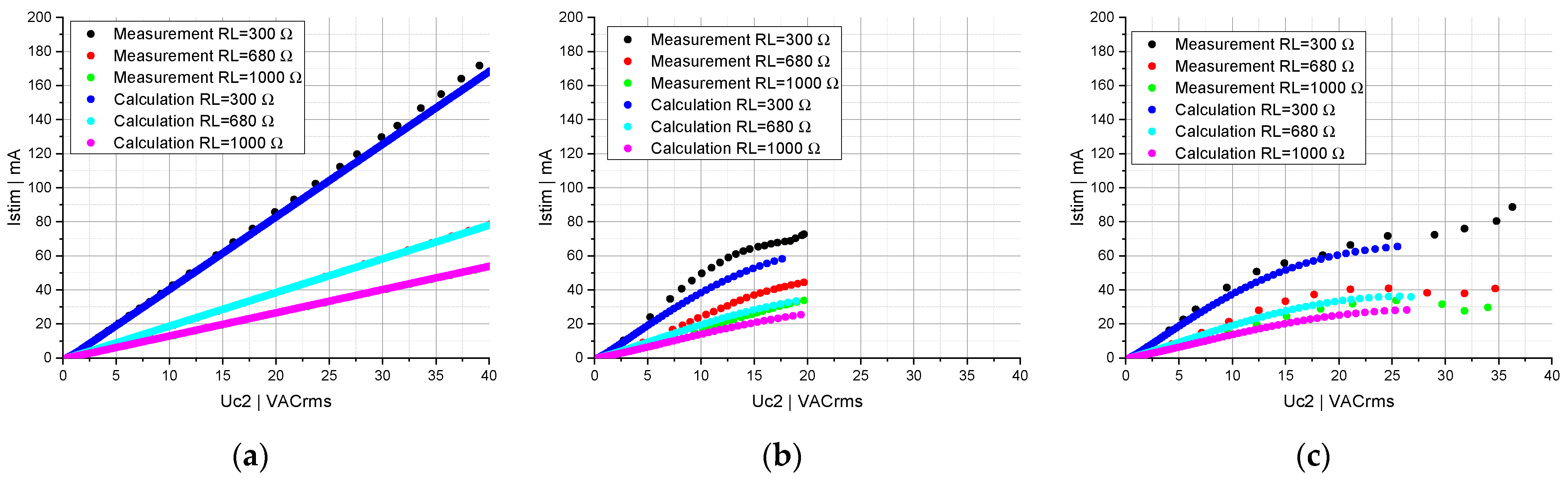
3.2. Circuit Topology Consisting of Two and Four Series-Connected Capacitors

For series-connected nonlinear capacitors, a poor stabilization of Istim can be observed (see Figure 7b,c and Figure 8b,c) compared to the circuit topology consisting of one nonlinear capacitor shown in Figure 6b. The induced voltage is distributed across the series-connected nonlinear capacitors, hence a higher value of Uc2 is needed to trigger the stabilization of Istim (see Figure 7c and Figure 8b,c). Furthermore, the series connection attenuates the voltage dependency of the resulting capacitance and, consequently, the nonlinearity of the circuit topology. By replacing one linear capacitor with a nonlinear one (see Figure 7b), no limitation of Istim can be seen at a load of 680 Ω and 1000 Ω.
A poor limitation of Istim at a load of 300 Ω can be observed in Figure 7b over a smaller range of Uc2 compared to the circuit topology consisting of two series-connected nonlinear capacitors (see Figure 7c). Assuming that even at higher AC voltages the linear capacitance is larger than the nonlinear capacitance over the entire voltage range (see Figure 5), a higher induced voltage will drop across the nonlinear capacitance in Figure 7b as in the case of two series-connected nonlinear capacitors (see Figure 7c).
No significant difference is observed for the circuit topology of four series-connected capacitors consisting of two linear and two nonlinear capacitors (see Figure 8b) and four nonlinear capacitors (see Figure 8c). For the series-connected capacitors in Figure 7c and Figure 8b,c, the calculations differs from the measurements for values of Uc2 above about 10 VACrms. This discrepancy is already apparent at a value of Uc2 above 5 VACrms in the series connection of a linear and nonlinear capacitor (see Figure 7b).

3.3. Circuit Topology Consisting of Two and Four Parallel-Connected Capacitors

In contrast to a circuit topology consisting of one nonlinear capacitor (see Figure 6b), two parallel-connected nonlinear capacitors (see Figure 9c) lead to a stronger limitation of Istim, however, over the same range of Uc2. Since the same voltage drops across both circuit topologies.
If two further nonlinear capacitors are connected in parallel, the nonlinearity of the circuit topology is enhanced, leading to a decrease in Istim at a value of Uc2 of approx. 20 VACrms (see Figure 10c). It can also be seen that those higher values of Istim are achieved and the stabilization of Istim is worse than with the circuit topology of two parallel-connected nonlinear capacitors (see Figure 9c). In the case of one linear and one nonlinear capacitor (see Figure 9b) as well as two linear and two nonlinear capacitors (see Figure 10b) connected in parallel, the relationship between Istim and Uc2 is mainly determined by the linear capacitors. A high consistency between measurement and calculation can be noted in this case. However, for the circuit topologies of parallel-connected nonlinear capacitors (see 9c and Figure 10c), the calculations differ from the measurements at higher values of Uc2, as previously described for the circuit topology consisting of one nonlinear capacitor (see Figure 6b).

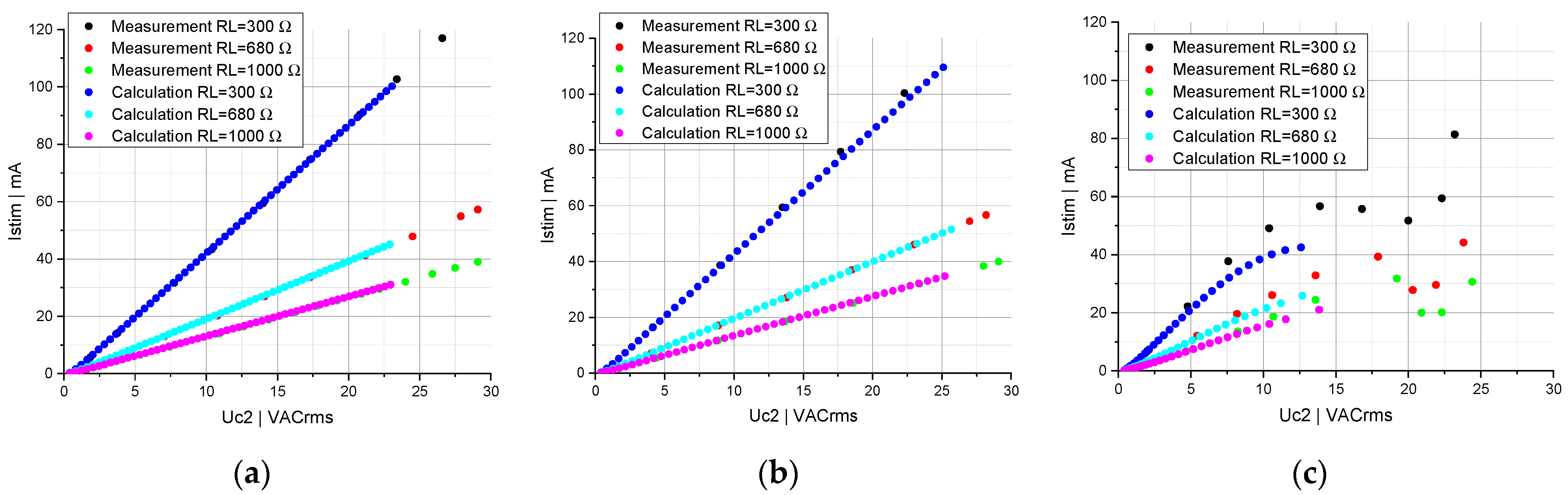
3.4. Circuit Topology Consisting of One Capacitor Connected in Series to Two Parallel-Connected Capacitors

As described above, the linear capacitor is dominant in a circuit topology consisting of a parallel-connected linear and nonlinear capacitor. Consequently, the same behavior can be observed between a linear capacitor series-connected to a parallel-connected linear and nonlinear capacitor (see Figure 11b) and two parallel-connected linear capacitors (see Figure 11a). A linear capacitor series-connected to two parallel-connected nonlinear capacitors results in a limitation of the stimulation current for values of Uc2 above about 30 VACrms at a load of 300 Ω and 680 Ω (see Figure 11c). At a load of 1000 Ω, no stabilization of Istim can be seen; moreover, the system becomes unstable at a value of Uc2 above 35 VACrms.
Depending on the combination of parallel-connected linear and/or nonlinear capacitors series-connected to a nonlinear capacitor, specific plateau ranges can be set (see Figure 12). The circuit topology consisting of a nonlinear capacitor series-connected to a parallel-connected linear and nonlinear capacitor (see Figure 12b) stands out from the other investigated topologies. At a load of 300 Ω, an increase in Istim close to a linear system can be obtained at a value of Uc2 below 25 VACrms. Above this threshold a significant limitation of Istim can be observed. Furthermore, it can be seen that the impact of the load on the plateau areas varies, depending on the circuit topology shown in Figure 12.

4. Discussion

In our previous investigations [27,28], the main focus was on the optimization in terms of consistency, computing time and memory-consumption of the model introduced in Mathcad and ANSYS. Circuit topologies consisting of one linear and nonlinear capacitor, two series-connected and two parallel-connected nonlinear capacitors were investigated at a constant load of 1 kΩ and frequency of 375 kHz.
In this paper, the previous investigations are expanded to different loads RL (300 Ω, 680 Ω and 1000 Ω), frequencies (between 183 kHz and 951 kHz) and 20 circuit topologies consisting of linear and/or nonlinear capacitors connected in series and/or in parallel. The resulting nonlinearity of the investigated topologies can be divided into three sections: (1) an approximately linear increase in the stimulation current, (2) a stabilization of the stimulation current, and (3) an unstable state of the system.
For the purpose of investigating the effect of the strong nonlinear behavior of the circuit topologies and the unstable state of the implantable system, the induced voltage was set to significantly higher values than the manufacturer’s rated voltage of the GRM022R60G473ME15L capacitors. Since the inductive power transfer was pulsed with a pulse duration between 2 ms and 9 ms and with a duty cycle below 1%, no damage to the capacitors was observed during the measurements.
By connecting linear and nonlinear capacitors in series or parallel, the nonlinearity can be attenuated or amplified, respectively. An overly weak nonlinearity leads to a poor stabilisation of the stimulation current, which only occurs for higher values of the induced voltage. Furthermore, the stabilization of the stimulation current is impaired by an overly high nonlinearity, which leads to an overshoot of the stimulation current as described in the circuit topology of four parallel-connected nonlinear capacitors (see Figure 10c). A circuit topology of series- and parallel-connected linear and nonlinear capacitors combines the advantageous properties of the topologies described above in terms of limitation of the stimulation current and system stability.
For lower values of the induced voltage, an approximately linear increase in the stimulation current can be observed, specific plateau ranges can be set and the unstable state of the system occurs for higher values of the induced voltage. In addition, it can be observed that a lower ohmic resistance RL leads to a higher stimulation current and vice versa for a circuit topology consisting of linear and nonlinear capacitors. It should be ensured that the stimulation current remains within a safe range for application-specific electrode impedances.
The resonant circuits of the inductively coupled system were matched for all measurements and calculations for small signals. Due to the voltage-dependent capacitance, the implantable circuit oscillates at different resonance frequencies depending on the induced voltage. It would be conceivable to use the frequency of the inductively coupled system to control the nonlinear properties of the circuit topologies of capacitors in the implantable circuit.
However, the investigated topologies of capacitors cannot be used for closed-loop control of the stimulation current. On one hand, the different plateau ranges are clearly above the current values used in electrostimulation [12], on the other hand, the circuit topologies are too unstable. Ideally, the stimulation current should be adjustable linearly over a small range of induced voltage and limited to a maximum current over a wide range of the induced voltage.
Designing a suitable circuit topology for the closed-loop control of the stimulation current by means of experimental characterization is not conceivable, by considering the numerous commercially available ferroelectric ceramic capacitors and their specific nonlinear properties. Currently, there are numerous simulation models for modeling voltage-dependent and ferroelectric capacitors described in the literature [32,33,34].
Nevertheless, datasheets and commercially available measuring instruments do not allow a representation of the capacitance over an AC voltage, e.g., +/−40 V and a frequency between 183 kHz and 951 kHz. In addition, the measurement of a voltage-dependent capacitance with a small AC voltage superimposed with a high DC bias voltage does not allow the correct modeling of the nonlinear properties of ferroelectric ceramic capacitors for higher AC voltages (see Figure 6, Figure 7, Figure 8, Figure 9, Figure 10, Figure 11 and Figure 12).
A high consistency between calculations and measurements can be achieved for circuit topologies consisting of almost voltage-independent capacitors. In contrast, for circuit topologies consisting of strongly voltage-dependent capacitors, the dynamic behavior of the system cannot be modeled properly for higher AC voltages. In other words, the measurement of voltage-dependent capacitors in Section 2.1 does not include the complex ferroelectric switching dynamics that occur at higher AC voltages and frequencies of inductive power transfer [35].
In order to design a circuit topology of nonlinear capacitors for the assessed embedded closed-loop stimulation current control, a model with high consistency for higher AC voltages must be provided. Since models of ferroelectric hysteretic materials exist [36,37], it is planned to incorporate such models into the model presented in this paper. Thereby, manufacturing and age-related parameter drift of ferroelectric materials could also be considered, which are of great importance for the long-term use and reliability of electroceuticals.

5. Conclusions

Frugal innovation enables the development of low-cost electroceuticals that offer high potential for further increasing the degree of miniaturization and reliability. The innovative approach presented in this work to realize a closed-loop control of the stimulation current by exploiting the nonlinear properties of ferroelectric materials in ceramic capacitors would allow to implement advanced functionalities in simply designed electroceuticals by following the principles of frugal engineering.
The results of this paper show that circuit topologies consisting of several capacitors connected in series and parallel are required to realize the embedded sensor functionality and closed-loop control of the power to generate the stimulation current. By using a circuit topology consisting of one capacitor connected in series to two parallel-connected capacitors and depending on their voltage dependency, the stimulation current can be stabilized to specific plateaus. It should also be noted that the sensitivity of the plateau range to a load change is affected by the circuit topology and the voltage dependency of the capacitors. This is particularly evident in Figure 12a–c.
In addition, the calculations in Mathcad show good agreement with measurements using circuit topologies consisting of capacitors with almost voltage-independent behavior. However, this model is not reliable for strong voltage-dependent ferroelectric capacitors at higher voltage ranges, since the measured differential capacitance does not reflect the complex electrical properties of the ferroelectric materials. Further investigation is needed in order to improve the consistency of the proposed model for higher induced voltage ranges.

Author Contributions

Writing—original draft preparation, methodology, formal analysis and investigation, Y.O.; writing—review and editing and supervision, F.R.I. All authors have read and agreed to the published version of the manuscript.

Funding

This research was funded by the German Federal Ministry of Education and Research (BMBF, funding number 16SV7637K). The authors are responsible for the content of this publication.

Institutional Review Board Statement

Not applicable.

Informed Consent Statement

Not applicable.

Data Availability Statement

Not applicable.

Acknowledgments

We thank Andreas Schütze from Saarland University and Thomas Velten from the Fraunhofer Institute for Biomedical Engineering for their support and fruitful discussions.

Conflicts of Interest

The authors declare no conflict of interest.

References

  1. Baptista, P.M.; Costantino, A.; Moffa, A.; Rinaldi, V.; Casale, M. Hypoglossal Nerve Stimulation in the Treatment of Obstructive Sleep Apnea: Patient Selection and New Perspectives. Nat. Sci. Sleep 2020, 12, 151–159. [Google Scholar] [CrossRef] [Green Version]
  2. Chakravarthy, K.V.; Xing, F.; Bruno, K.; Kent, A.R.; Raza, A.; Hurlemann, R.; Kinfe, T.M. A Review of Spinal and Peripheral Neuromodulation and Neuroinflammation: Lessons Learned Thus Far and Future Prospects of Biotype Development. Neuromodulation 2018, 22, 235–243. [Google Scholar] [CrossRef]
  3. Eastwood, P.R.; Barnes, M.; Mackay, S.G.; Wheatley, J.R.; Hillman, D.R.; Nguyên, X.-L.; Lewis, R.; Campbell, M.C.; Pételle, B.; Walsh, J.H.; et al. Bilateral hypoglossal nerve stimulation for treatment of adult obstructive sleep apnoea. Eur. Respir. J. 2019, 55, 1901320. [Google Scholar] [CrossRef]
  4. Hofmeister, M.; Memedovich, A.; Brown, S.; Saini, M.; Dowsett, L.E.; Lorenzetti, D.L.; McCarron, T.L.; MacKean, G.; Clement, F. Effectiveness of Neurostimulation Technologies for the Management of Chronic Pain: A Systematic Review. Neuromodulation 2020, 23, 150–157. [Google Scholar] [CrossRef]
  5. Moeller, S.; Lücke, C.; Heinen, C.; Bewernick, B.H.; Aydin, M.; Lam, A.P.; Grömer, T.W.; Philipsen, A.; Müller, H.H.O. Vagus Nerve Stimulation As an Adjunctive Neurostimulation Tool in Treatment-resistant Depression. J. Vis. Exp. 2019, e58264. [Google Scholar] [CrossRef] [Green Version]
  6. Wirth, T.; Laurencin, C.; Berthillier, J.; Brinzeu, A.; Polo, G.; Simon, E.; Mertens, P.; Broussolle, E.; Danaila, T.; Thobois, S. Feasibility of changing for a rechargeable constant current neurostimulator in Parkinson’s disease. Rev. Neurol. 2021, 177, 283–289. [Google Scholar] [CrossRef] [PubMed]
  7. Díaz-De-Terán, J.; Membrilla, J.A.; Paz-Solís, J.; de Lorenzo, I.; Roa, J.; Lara-Lara, M.; Gil-Martínez, A.; Díez-Tejedor, E. Occipital Nerve Stimulation for Pain Modulation in Drug-Resistant Chronic Cluster Headache. Brain Sci. 2021, 11, 236. [Google Scholar] [CrossRef]
  8. Ingegnoli, F.; Buoli, M.; Antonucci, F.; Coletto, L.A.; Esposito, C.M.; Caporali, R. The Link Between Autonomic Nervous System and Rheumatoid Arthritis: From Bench to Bedside. Front. Med. 2020, 7, 589079. [Google Scholar] [CrossRef] [PubMed]
  9. Kaniusas, E.; Szeles, J.C.; Kampusch, S.; Alfageme-Lopez, N.; Yucuma-Conde, D.; Li, X.; Mayol, J.; Neumayer, C.; Papa, M.; Panetsos, F. Non-invasive Auricular Vagus Nerve Stimulation as a Potential Treatment for Covid19-Originated Acute Respiratory Distress Syndrome. Front. Physiol. 2020, 11, 890. [Google Scholar] [CrossRef] [PubMed]
  10. Sandoval-Munoz, C.P.; Haidar, Z.S. Neuro-Muscular Dentistry: The “diamond” concept of electro-stimulation potential for stomato-gnathic and oro-dental conditions. Head Face Med. 2021, 17, 1–16. [Google Scholar] [CrossRef] [PubMed]
  11. Paff, M.; Loh, A.; Sarica, C.; Lozano, A.M.; Fasano, A. Update on Current Technologies for Deep Brain Stimulation in Parkinson’s Disease. J. Mov. Disord. 2020, 13, 185–198. [Google Scholar] [CrossRef]
  12. Kassiri, H.; Tonekaboni, S.; Salam, M.T.; Soltani, N.; Abdelhalim, K.; Velazquez, J.L.P.; Genov, R. Closed-Loop Neurostimulators: A Survey and A Seizure-Predicting Design Example for Intractable Epilepsy Treatment. IEEE Trans. Biomed. Circuits Syst. 2017, 11, 1026–1040. [Google Scholar] [CrossRef] [PubMed]
  13. Medtronic. Product Performance Report 2019: Summary of Data from the Medtronic Post-Market Registry. 2020. Available online: https://www.medtronic.com/content/dam/medtronic-com/products/product-performance/ppr-reports/2019-product-performance-report-combined.pdf?bypassIM=true (accessed on 23 March 2021).
  14. Lu, G.; Luo, L.; Liu, M.; Zheng, Z.; Zhang, B.; Chen, X.; Hua, X.; Fan, H.; Mo, G.; Duan, J.; et al. Outcomes and Adverse Effects of Deep Brain Stimulation on the Ventral Intermediate Nucleus in Patients with Essential Tremor. Neural Plast. 2020, 2020, 2486065. [Google Scholar] [CrossRef] [PubMed]
  15. Sterman, J.; Cunqueiro, A.; Dym, R.J.; Spektor, M.; Lipton, M.L.; Revzin, M.V.; Scheinfeld, M.H. Implantable Electronic Stimulation Devices from Head to Sacrum: Imaging Features and Functions. Radiographics 2019, 39, 1056–1074. [Google Scholar] [CrossRef]
  16. Neely, R.M.; Piech, D.K.; Santacruz, S.R.; Maharbiz, M.M.; Carmena, J.M. Recent advances in neural dust: Towards a neural interface platform. Curr. Opin. Neurobiol. 2018, 50, 64–71. [Google Scholar] [CrossRef] [PubMed]
  17. Jang, S.G.; Kim, J.; Lee, J.; Kim, J.S.; Kim, D.H.; Park, S.M. Wireless Power Transfer Based Implantable Neurostimulator. In Proceedings of the 2020 IEEE Wireless Power Transfer Conference (WPTC), Seoul, Korea, 15–19 November 2020; pp. 365–368. [Google Scholar]
  18. Khalifa, A.; Liu, Y.; Bao, Z.; Etienne-Cummings, R. A Compact Free-Floating Device for Passive Charge-Balanced Neural Stimulation using PEDOT/CNT microelectrodes. In Proceedings of the 42nd Annual International Conference of the IEEE Engineering in Medicine & Biology Society (EMBC), Montreal, QC, Canada, 20–24 July 2020; pp. 3375–3378. [Google Scholar] [CrossRef]
  19. KEMET. C1812C474J5JACTU. Available online: https://connect.kemet.com:7667/gateway/IntelliData-ComponentDocumentation/1.0/download/specsheet/C1812C474J5JACTU (accessed on 15 June 2021).
  20. Murata. Product Search Data Sheet: GRM022R60G473ME15#. Available online: https://www.murata.com/en-global/api/pdfdownloadapi?cate=luCeramicCapacitorsSMD&partno=GRM022R60G473ME15%23 (accessed on 15 June 2021).
  21. Kahn, M. Multilayer Ceramic Capacitors Materials and Manufacture. Available online: https://www.avx.com/docs/techinfo/CeramicCapacitors/mlcmat.pdf (accessed on 7 July 2021).
  22. Pan, M.-J.; Randall, C.A. A brief introduction to ceramic capacitors. IEEE Electr. Insul. Mag. 2010, 26, 44–50. [Google Scholar] [CrossRef]
  23. Jiang, W.; Hu, Y.; Bao, S.; Lijie, S.; Yuwei, Z.; Cui, Y.; Qiang, L.; Wei, J. Analysis on the causes of decline of MLCC insulation resistance. In Proceedings of the 16th International Conference on Electronic Packaging Technology (ICEPT), Changsha, China, 11–14 August 2015; IEEE: Piscataway, NJ, USA; pp. 1255–1257, ISBN 978-1-4673-7999-1. [Google Scholar]
  24. Haertling, G.H. Ferroelectric Ceramics: History and Technology. J. Am. Ceram. Soc. 1999, 82, 797–818. [Google Scholar] [CrossRef]
  25. Setter, N.; Damjanovic, D.; Eng, L.; Fox, G.R.; Gevorgian, S.; Hong, S.; Kingon, A.I.; Kohlstedt, H.; Park, N.Y.; Stephenson, G.B.; et al. Ferroelectric thin films: Review of materials, properties, and applications. J. Appl. Phys. 2006, 100, 051606. [Google Scholar] [CrossRef]
  26. Borafker, S.; Drujin, M.; Ben-Yaakov, S.S. Voltage-Dependent-Capacitor Control of Wireless Power Transfer (WPT). In Proceedings of the IEEE International Conference on the Science of Electrical Engineering in Israel (ICSEE), Elat, Israe, 12–14 December 2018; IEEE: Piscataway, NJ, USA; pp. 1–4, ISBN 978-1-5386-6378-3. [Google Scholar]
  27. Olsommer, Y.; Ihmig, F.R. Consistent and Efficient Modeling of the Nonlinear Properties of Ferroelectric Materials in Ceramic Capacitors for Frugal Electronic Implants. Sensors 2020, 20, 4206. [Google Scholar] [CrossRef]
  28. Olsommer, Y.; Ihmig, F.R.; Müller, C. Modeling the Nonlinear Properties of Ferroelectric Materials in Ceramic Capacitors for the Implementation of Sensor Functionalities in Implantable Electronics. Proceedings 2019, 42, 61. [Google Scholar] [CrossRef] [Green Version]
  29. TDK Corporation. Delivery Specification: Multilayer Ceramic Chip Capacitor. Available online: https://product.tdk.com/system/files/dam/doc/product/capacitor/ceramic/mlcc/specification/mlccspec_automotive_general_en.pdf (accessed on 15 June 2021).
  30. Murata. GRM Series: Chip Multilayer Ceramic Capacitors for General Purpose. Available online: https://www.murata.com/products/capacitor/ceramiccapacitor/overview/lineup/smd/grm (accessed on 15 June 2021).
  31. Murata. Structure and Material of Chip Multilayer Ceramic Capacitor. Available online: https://search.murata.co.jp/Ceramy/image/img/A01X/1R0212B.pdf (accessed on 15 June 2021).
  32. Jadli, U.; Mohd-Yasin, F.; Moghadam, H.A.; Nicholls, J.R.; Pande, P.; Dimitrijev, S. The Correct Equation for the Current Through Voltage-Dependent Capacitors. IEEE Access 2020, 8, 98038–98043. [Google Scholar] [CrossRef]
  33. Gourary, M.M.; Rusakov, S.G.; Ulyanov, S.L.; Zharov, M.M.; Rassadin, A.E. SPICE models of nonlinear capacitors for simulation of ferroelectric circuits. In Proceedings of the IEEE East-West Design & Test Symposium (EWDTS), Novi Sad, Serbia, 29 September–2 October 2017; IEEE: Piscataway, NJ, USA; pp. 1–4, ISBN 978-1-5386-3299-4. [Google Scholar]
  34. Fatoorehchi, H.; Abolghasemi, H.; Zarghami, R. Analytical approximate solutions for a general nonlinear resistor–nonlinear capacitor circuit model. Appl. Math. Model. 2015, 39, 6021–6031. [Google Scholar] [CrossRef]
  35. Leschhorn, A.; Djoumbou, S.; Kliem, H. Microscopic model of domain wall motion. J. Appl. Phys. 2014, 115, 114106. [Google Scholar] [CrossRef]
  36. Alessandri, C.; Pandey, P.; Abusleme, A.; Seabaugh, A. Monte Carlo Simulation of Switching Dynamics in Polycrystalline Ferroelectric Capacitors. IEEE Trans. Electron Devices 2019, 66, 3527–3534. [Google Scholar] [CrossRef]
  37. Maslovskaya, A.; Moroz, L.; Chebotarev, A.; Kovtanyuk, A. Theoretical and numerical analysis of the Landau–Khalatnikov model of ferroelectric hysteresis. Commun. Nonlinear Sci. Numer. Simul. 2021, 93, 105524. [Google Scholar] [CrossRef]
Figure 1. Typical structure of a multilayer ceramic chip capacitor (MLCC) with: (1) ceramic dielectric layers, (2) inner electrode layers and (3, 4, 5) termination electrodes. The termination electrodes consist of: (5) a substrate layer for connecting the termination to the inner electrodes, (4) a barrier layer as thermal protection of the dielectric from soldering and an external layer (3) for soldering the MLCC.
Electronicmat 02 00021 g001
Figure 2. Inductively coupled system for power transfer consisting of an extracorporeal transmitter (left) and an implantable electronic circuit (right). The extracorporeal transmitter consists of a resonant half-bridge converter, a capacitor C1, an inductance L1 and a loss resistor R1. The implantable electronic circuit consists of a parallel resonant circuit, which is composed of the inductance L2, loss resistor R2 and a circuit topology of ceramic capacitors, a half-wave rectifier consisting of the diode D1 and capacitor C4 and an ohmic load RL representing the electrode impedance. The inductive coupling between the extracorporeal transmitter and the implantable electronic circuit is represented by the coupling factor k.
Electronicmat 02 00021 g002
Figure 3. Exemplary representation of the pulsed inductive power supply of the implantable electronics. Induced voltage uC2 (t) (left) and rectified stimulation current iStim (t) (right) versus time t.
Electronicmat 02 00021 g003
Figure 4. Circuit topologies of voltage-dependent ceramic capacitors with: (a) one capacitor; (b) two series-connected capacitors; (c) four series-connected capacitors; (d) two parallel-connected capacitors; (e) four parallel-connected capacitors; (f) one capacitor connected in series to two parallel-connected capacitors.
Electronicmat 02 00021 g004
Figure 5. Measured capacitance C according to the bias voltage of the capacitor CGA5L1X7T2J473K160AC and GRM022R60G473ME15L at a frequency of 360 kHz and 400 kHz, respectively (N = 8).
Electronicmat 02 00021 g005
Figure 6. Stimulation current Istim as a function of the induced voltage Uc2 for a circuit topology consisting of: (a) linear capacitor; (b) nonlinear capacitor. The measurements (black, red, green) and calculations (blue, cyan, magenta) were performed for RL = 300 Ω, 680 Ω and 1000 Ω, respectively.
Electronicmat 02 00021 g006
Figure 7. Stimulation current Istim as a function of the induced voltage Uc2 for a circuit topology of two series-connected: (a) linear capacitors; (b) linear and nonlinear capacitors; (c) nonlinear capacitors. The measurements (black, red, green) and calculations (blue, cyan, magenta) were performed for RL = 300 Ω, 680 Ω and 1000 Ω, respectively.
Electronicmat 02 00021 g007
Figure 8. Stimulation current Istim as a function of the induced voltage Uc2 for a circuit topology of: (a) four series-connected linear capacitors; (b) two series-connected linear and two series-connected nonlinear capacitors; (c) four series-connected nonlinear capacitors. The measurements (black, red, green) and calculations (blue, cyan, magenta) were performed for RL = 300 Ω, 680 Ω and 1000 Ω, respectively.
Electronicmat 02 00021 g008
Figure 9. Stimulation current Istim as a function of the induced voltage Uc2 for a circuit topology of two parallel-connected capacitors consisting of: (a) two linear capacitors; (b) a linear and a nonlinear capacitor; (c) two nonlinear capacitors. The measurements (black, red, green) and calculations (blue, cyan, magenta) were performed for RL = 300 Ω, 680 Ω and 1000 Ω, respectively.
Electronicmat 02 00021 g009
Figure 10. Stimulation current Istim as a function of the induced voltage Uc2 for a circuit topology of four parallel-connected capacitors consisting of: (a) four linear capacitors; (b) two linear and two nonlinear capacitors; (c) four nonlinear capacitors. The measurements (black, red, green) and calculations (blue, cyan, magenta) were performed for RL = 300 Ω, 680 Ω and 1000 Ω, respectively.
Electronicmat 02 00021 g010
Figure 11. Stimulation current Istim as a function of the induced voltage Uc2 for a circuit topology of one linear capacitor series-connected to two parallel-connected: (a) linear capacitors; (b) linear and nonlinear capacitors; (c) nonlinear capacitors. The measurements (black, red, green) and calculations (blue, cyan, magenta) were performed for RL = 300 Ω, 680 Ω and 1000 Ω, respectively.
Electronicmat 02 00021 g011
Figure 12. Stimulation current Istim as a function of the induced voltage Uc2 for a circuit topology of one nonlinear capacitor series-connected to two parallel-connected: (a) linear capacitors; (b) linear and nonlinear capacitors; (c) nonlinear capacitors. The measurements (black, red, green) and calculations (blue, cyan, magenta) were performed for RL = 300 Ω, 680 Ω and 1000 Ω, respectively.
Electronicmat 02 00021 g012
Publisher’s Note: MDPI stays neutral with regard to jurisdictional claims in published maps and institutional affiliations.

