1. Introduction
Structures can be significantly affected by explosions and terrorist threats, with lighter structures being more vulnerable than their more substantial counterparts. Such threats often result in external surface explosions around buildings. Perforated steel members (PSMs) play an important role in fulfilling serviceability requirements through structural beams and columns, in addition to their economic and aesthetic advantages. PSMs are pivotal in either increasing or mitigating damage to structures when exposed to various blast scenarios, in comparison to traditional steel sections. The adoption of PSMs is on the rise because of their aesthetic and economic benefits. These members are crafted from steel I-sections, which are cut and then welded back together, creating a deeper section and consistent web openings throughout their length [
1]. The flexural behavior of perforated steel beams (PSBs) is considerably more intricate than that of solid webs. Various failure modes can arise, including the Vierendeel mechanism failure, local web buckling, and weld shear rupture in the web post [
2]. When structures that incorporate beams like PSBs experience intense local damage due to blast loading, it can lead to the collapse of the entire structure. As a result, studying the dynamic response of these beams has become a crucial area of research. A previous numerical campaign was carried out to validate the design procedure for ductile seismic-resistant and moment-resisting frames and joints [
3,
4,
5].
Much of the prior research on steel has focused on the behavior of solid steel beams. Lee et al. [
6] simulated the intricate interplay between the blast wave and wide-flange steel components using computational fluid dynamics methods and FE analysis. The impact of blasts on the load-bearing ability of I-shaped steel components was assessed, taking into account different factors such as the detonation shape, the location of the initiation point, and the amount of explosive used [
7]. A non-discretization numerical approach was employed to study steel beams subjected to blast loading [
8]. The single-degree-of-freedom (SDOF) model served as a validation tool for test outcomes from nonlinear dynamic analyses on steel beams exposed to blast loads [
9,
10,
11,
12]. Furthermore, numerous theoretical studies have been conducted to describe the SDOF analysis of beam–column elements under blast effects. Shope [
13] formulated simplified analytical techniques for steel components under blast loads combined with static axial compression. The influences of the P-δ and strain rate were integrated into the SDOF analysis [
11]. Three-dimensional evaluations using Finite Element (FE) software tools, such as LSDYNA [
14], offer a more precise representation of dynamic behavior, taking into account both local and overarching deformations during blast exposure. Additionally, numerical simulations present more cost and time-efficient alternatives to hands-on experiments.
While there is an extensive amount of research on solid steel elements, utilizing both experimental results and numerical studies for damage assessment, the behavior of steel elements with perforated webs under the large deformations typical in blast design remains underexplored. Additionally, there is a notable gap in research concerning the influence of web opening designs, boundary conditions, and reinforcement details on enhancing the strength and ductility of perforated steel columns, which significantly determine their resistance to blast-induced failures. Therefore, in this study, numerical examinations of damage assessment under the combined effects of gravity and blast loads are carried out to mimic real-world scenarios of external explosions close to perforated steel columns in comparison to the perforated steel beams presented in [
1]. The damage assessment for PSBs and PSCs considers not only the initial deformation caused by the blast, but also takes into account the residual capacity to formulate dependable damage metrics post-explosion. Comprehensive explicit finite element (FE) analyses are performed with the LSDYNA software.
2. Numerical Modelling
As computational mechanics has evolved, numerical methods have emerged as crucial tools for modeling the behavior and assessing the damage of steel structures exposed to blast loading. In this context, this paper utilizes the advanced FE code LSDYNA [
14] to evaluate the potential damage of PSBs and PSCs during blast exposure.
2.1. Modeling of Materials
The LSDYNA software [
14] excels in performing intricate non-linear dynamic analyses, pivotal for assessing the dynamic behaviors of PSBs and PSCs under blast conditions. This program characterizes steel properties, especially those influenced by strain rates, using a distinct nonlinear material command termed MAT_PELASTIC_KINEMATIC (MAT_003). This command is tailor-made for simulating materials with kinematic hardening plasticity features. Both strain hardening and elevated strain rate influences are encompassed within the dynamic increase factor (DIF) [
14,
15], which draws from the Cooper–Simonds relationship [
16], depicted in Equation (1).
where
is the material strain rate and
P and
C are constant coefficients that are set equal to 40.4 and 5, respectively, as suggested in [
16].
2.2. Selection of Elements
For enhanced accuracy and computational efficiency in our results, it was imperative to meticulously choose both the type and size of the elements. Finite Element (FE) models for PSBs and PSCs are formulated using either shell or solid elements. In our validation study, we conducted a convergence analysis, comparing two specific elements for each tested setup. This approach aimed to closely mirror the outcomes of field experiments found in the prevailing literature. In the shell models, we adopted quadrilateral elements with five integration points, as specified by the “ELFORM = 16” option. This choice facilitated a comprehensive representation of the potential damage caused during significant deformations and strains within each element’s thickness [
17]. On the other hand, for solid models, we opted for eight-node brick elements integrated with a robust solid formulation, identified by the “ELFORM = 2” option, spanning the element’s surface [
18].
2.3. Geometry and Boundary Conditions
A myriad of experimental and FE optimization studies have delved into the diverse web-opening shapes of PSBs and PSCs, as highlighted in references [
19,
20]. Nawar et al. [
21] undertook a comprehensive static analysis of perforated web shapes, focusing on configurations such as hexagonal, sinusoidal, circular, and elongated circular holes. Recognizing the paramount significance of these shapes when exposed to blast forces,
Figure 1 and
Figure 2 offer detailed schematic illustrations of the PSBs and PSCs, respectively, when subjected to blast pressure, spotlighting four key web opening patterns: hexagonal, sinusoidal, circular, and elongated circular holes.
At both ends of the steel member, two rigid plates are affixed to distinct pinned and fixed boundary conditions in the shell and solid model setups. The pinned conditions utilize line nodes spanning the width of the plate, allowing rotations while limiting translations. Conversely, the fixed conditions are pinpointed at nodes matching the expected bolt positions, constricting both rotational and translational movements.
2.4. Methodology of Blast Loading and Application of the Combined Loadings
In the finite element (FE) simulation, the ‘LOAD BLAST ENHANCED’ command was employed within LS-DYNA to replicate explosive loading conditions. This command harnesses CONWEP data, which are based on empirical relationships derived from real-world blasting tests, to accurately model blast characteristics. The interaction between the blast wave and the steel member was defined using the ‘LOAD_BLAST_SEGMENT_SET’ function. The CONWEP software is proficient in calculating the critical explosion load parameters, such as the reflected pressure and positive phase duration values.
Figure 3 illustrates the blast loading profile for the incident and reflected pressure. Further details of the methodology used to apply combined loadings are elaborated upon in the subsequent sections.
2.4.1. For the PSBs
To fully gauge the resilience of PSBs, especially in the aftermath of blast events, it is essential to integrate both quasi-static and blast loads. This approach is broken down into a phased numerical strategy, crafted to determine this residual strength. The first stage is before the arrival of the blast loading. In this stage, quasi-static loading is applied as the primary gravity service load, equivalent to 20% of the PSBs’ flexural capacity to obtain elastic behavior without permanent deformation (before yielding). To ensure that the gravity service loading is quasi-static, the kinetic energies of the models are checked to be less than 5% of their internal energies. Then, the lateral pressure of the explosion is applied to the PSBs over a duration of 50 msec. The blast is instantly loaded as shown in
Figure 4. After the blast shot, reductions in the strength capacities of the PSBs are obtained. To explore the residual flexural capacities of the beams, the gravity load is magnified and applied gradually as uniformly distributed loading on the upper flange of the beams until failure.
Figure 4 visually depicts this analytic procedure, culminating when the nodal velocities approach zero; the gravity load is then methodically increased.
2.4.2. For the PSCs
To harness the full capacity of the PSCs, quasi-static loads are applied to simulate residual stresses. Following the blast loading, axial gravity loads are gradually introduced to amplify the residual axial-bearing capacity.
Figure 5 depicts this analytical approach, carried forward until the node velocities approach a zero value. Subsequently, the gravity load is progressively increased until the structure collapses. This multi-stage numerical strategy unfolds in several steps: First, a quasi-static primary gravity axial load is imposed, equivalent to 20% of the PSCs’ axial capacity, as outlined in [
23,
24], over a duration of 50 msec. This precedes the introduction of lateral blast pressure. In the subsequent phase, the dynamic evaluation continues post-explosion until vibrations are adequately attenuated and all nodal velocities fall beneath 0.1 m/sec. In the final step, the gravity load (or the axial load for the column) is progressively amplified until the column fails. The highest axial load attained at this point is recognized as the residual axial bearing capacity of the PSCs, as mentioned in [
25].
2.5. Damage and Failure Criteria
In this section, we propose a specialized damage index designed to evaluate the susceptibility of PSBs and PSCs to combined gravity–blast loadings. Typically, damage assessment under the influence of blast involves analyzing support rotations and their associated ductility ratios. The anticipated support rotations (θ) are derived from the maximum mid-span displacement (U
max) in relation to the length (L) of the structural elements [
23,
24], as presented in Equation (2) [
26,
27]. The ductility ratio (μ) is defined as the ratio of peak deflection to its elastic value. According to UFC standards [
27], damage parameters for primary steel frame members are established using support rotation and ductility ratio indicators. UFC provisions [
27] outline the damage levels for primary steel frame members, taking into account both those without and with significant compression. These levels are based on the support rotation and ductility ratio.
Table 1 presents the acceptable rotation and ductility ratio benchmarks for steel structural members as per the UFC provision [
27].
It is important to note that blast-related damages intensify under gravity loads. As a result, relying solely on traditional metrics like ductility ratios and support rotation thresholds might not provide an accurate portrayal of specific post-blast damages, such as the vierendeel failures seen in PSBs and PSCs. This highlights the need for an alternative measure for the damage index (D) that centers on the residual capabilities of the beam, as presented in [
28] as follows.
2.5.1. For the PSBs
Equations (3) and (4) outline the procedures used to the derive damage indices, accounting for both bending and shear impacts on the PSBs.
where M
initial and V
initial are the maximum moments and shear capacities of the undamaged beam, and M
residual and V
residual are the residual capacities of the damaged beam after the explosion. Each of the Vresidual, Vinitial, Mresidual, and Minitial values are obtained from the FE analyses.
2.5.2. For the PSCs
The damage index (D), which is predicated on the PSCs’ residual axial load capacity, is employed to investigate the post-blast damages as described:
where P
initial is the peak axial load-bearing capacity of the intact column and P
residual is the remaining axial load-bearing capacity of the column post-explosion. The Pinitial and Presidual values are obtained from the FE analyses.
2.5.3. Damage Levels
Based on the damage index [
28], damage levels are categorized into four distinct tiers. The ‘Low Damage’ level corresponds to a damage index (D) spanning from 0 to 0.2. The ‘Medium Damage’ corresponds to a range of 0.2–0.5, while the ‘High Damage’ level corresponds to 0.5–0.8. A range of 0.8–1.0 designates a complete collapse. Running these analyses is significantly time-consuming. In the LS-DYNA framework, the CONTROL_TERMINATION card oversees this process duration. To enhance the efficiency and curtail computational efforts, during the third loading stage, an extra 20% damping is applied between the 150 and 500 ms interval, reducing the nodal velocities to an acceptable level. This adaptive damping not only expedites the simulation process, but also retains the precision of capturing the beams’ residual strengths.
3. Validation of the FE Models
3.1. For the Steel Beam under Blast Exposure
The accuracy of the FE models is assessed in terms of sensitivity, and these models are compared with the past experimental findings of Nassr et al. [
9] for validation. Three specimens from experimental tests (1B, 2B, and 3B) are selected to verify the steel beam models. These specimens are derived from three different explosion shots and have a solid W150 × 24 section type with a standard length of 2413 mm. The static nominal yield stress and ultimate strength of the steel section are 393 and 537 MPa, respectively. In both the first and third tests, the beam faces explosive charges of 50 kg and 100 kg, respectively, of ANFO at a uniform distance of 10.3 m. However, in the second test, the beam is exposed to a 150 kg ANFO explosive charge at a 9 m distance. It is noteworthy that ANFO’s explosive energy is around 82% that of TNT. For the purpose of this validation study, the beam ends are modeled as pinned. The explosive forces are spread consistently along the beam’s length. In tests 1 and 3, the beam bends around its strong axis, whereas in test 2, it is oriented towards its weak axis. The experimental steel samples come with specific properties: a density of 7850 kg/m
3, a yield strength of 470 MPa, an elastic modulus of 210 GPa, a Poisson’s ratio of 0.3, and a failure strain of 0.2. In experiments 1, 2, and 3, the transducers recorded average peak reflected pressures of 307, 623, and 1560 kPa, respectively. Meanwhile, the average durations for the positive phase were 7.3, 6.0, and 6.2 ms for the respective tests.
Two models, one with solid elements and the other with shell elements, are evaluated to understand the impact of the element type and dimension on the precision of the FE results. Convergence studies indicate that reducing the mesh size has a minimal impact on numerical outcomes, but that it significantly extends the computation time. Therefore, elements with a dimension of 20 mm are advised, as the displacements achieved using both shell and solid elements with sizes of 15 mm or 10 mm closely align with those of 20 mm.
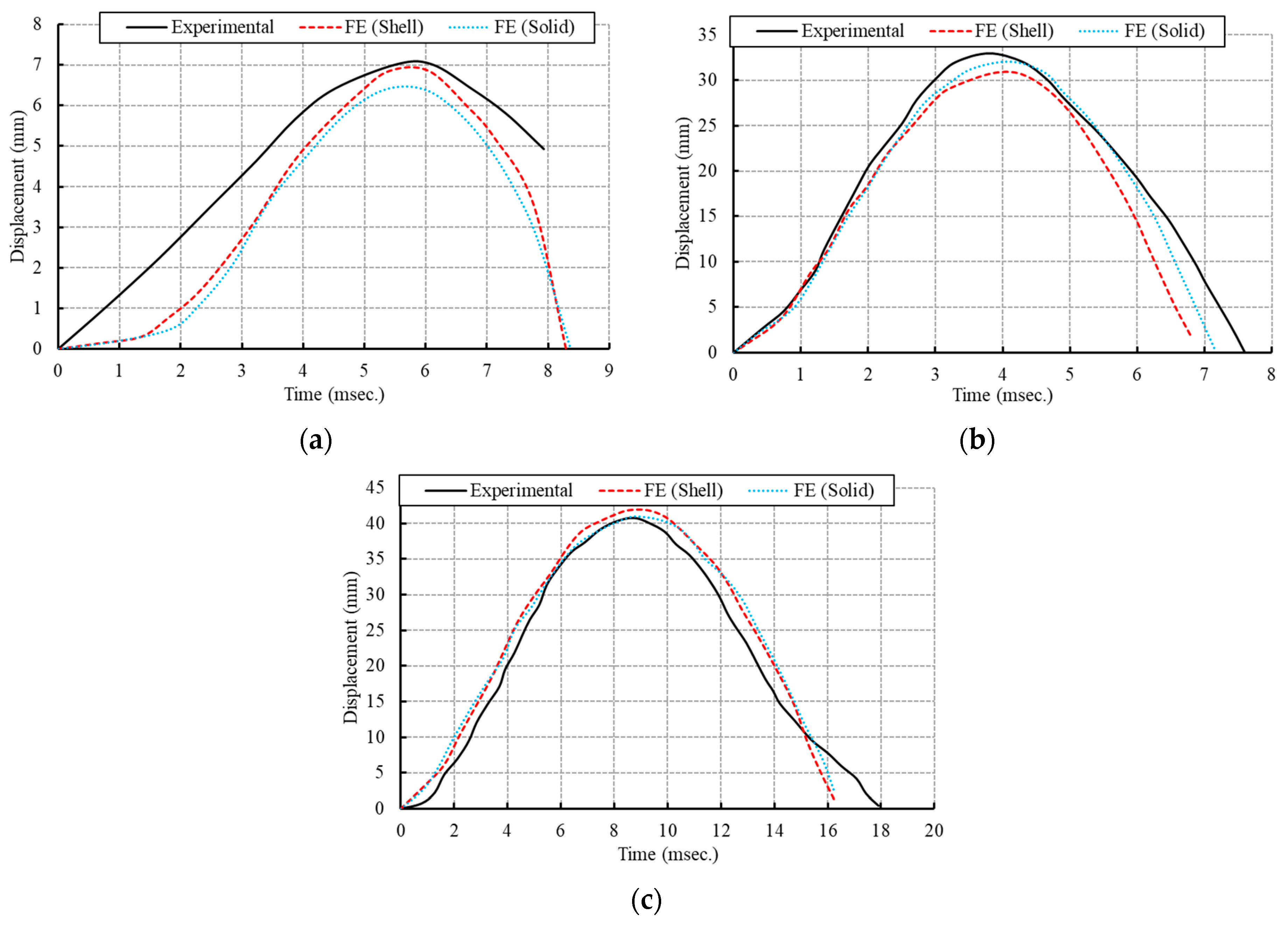
Figure 6 presents a side-by-side comparison of the mid-span displacement time history obtained from both the FE and experimental results. Additionally,
Table 2 provides an in-depth breakdown of the FE model outcomes, juxtaposed with experimental data; this focuses on key metrics like the peak reflected pressures (P
r), the reflected impulse (I
r), positive phase duration (td), the maximum displacement (U
max), maximum strain (ε
max), and the maximum strain rate (S
r).
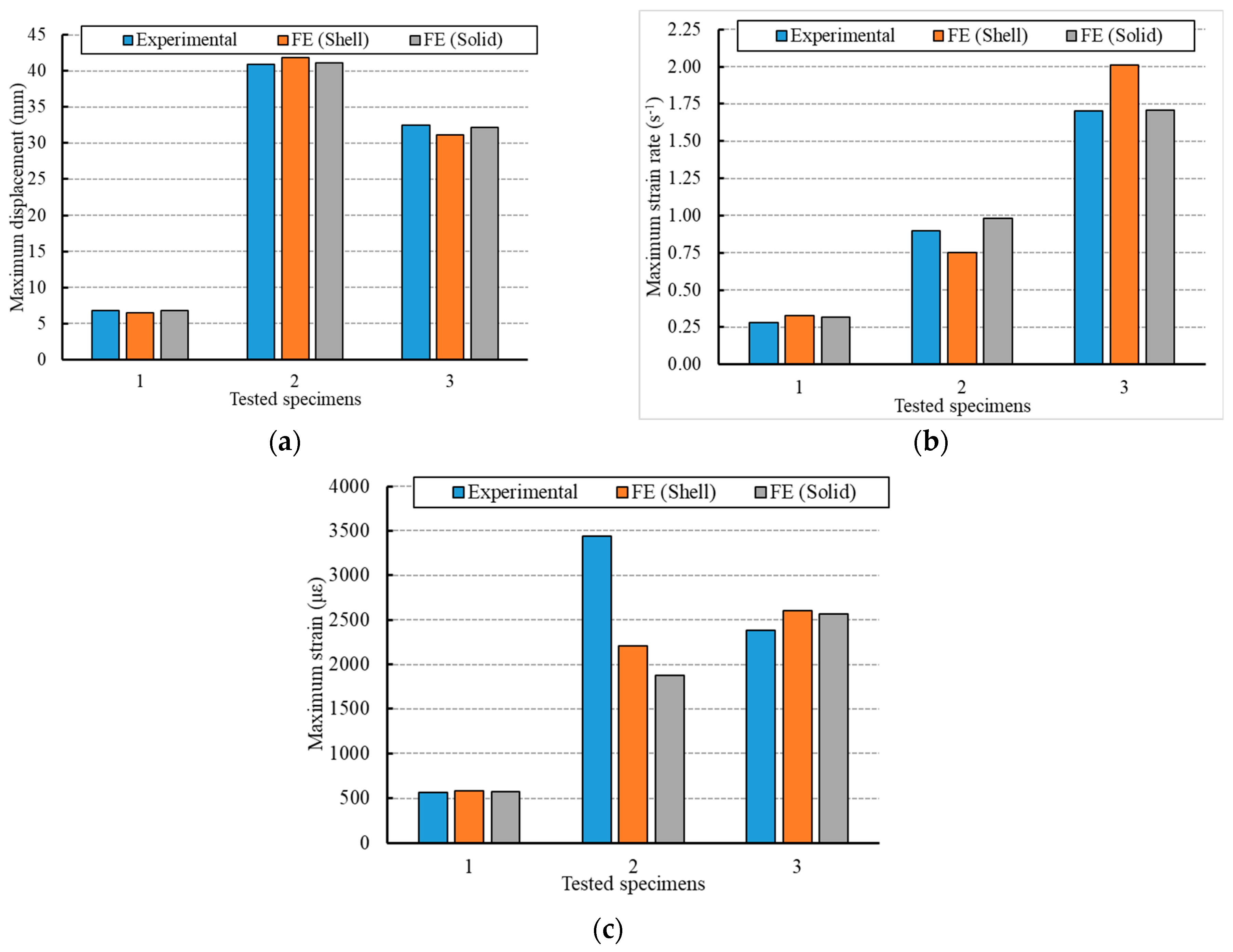
Figure 7 provides comparisons between the FE and experimental outcomes in terms of the maximum displacement at the mid-span, maximum strain, and maximum strain rate. The average peak reflected pressures obtained using the FE model with shell elements deviated by 2%, 3%, and 16.3%, respectively, from the experimental results. In contrast, with solid elements, the deviations were 0.7%, 0.2%, and 6.7%. When considering the predicted reflected impulse based on the pressure–time profiles, the shell elements showed variances of 8.3%, 2.2%, and 1.6%. Yet, with solid elements, these variances were 6.6%, 2.5%, and 7% when juxtaposed with the experimental test values. On the whole, the FE models’ estimated positive phase durations varied by 31.5% to 63%. Additionally, the mid-span strain–time histories of the evaluated beams differed by 0.5% to 59.4% in comparison to the experimental outcomes.
When comparing results, the maximum displacements derived from the shell FE models showed differences of 5.2%, 2.1%, and 4.4% for steel beams 1B, 2B, and 3B, respectively. In contrast, the deviations for the maximum displacements from the solid FE models were 0.2%, 0.2%, and 1%. Despite the minor discrepancies between the predictive FE values and experimental data, the current solid FE models demonstrated superior computational efficiency relative to the shell models. As such, the use of fully integrated solid elements is recommended for FE models when forecasting the behavior of steel beams under blast loads.
3.2. For the Steel Column under Blast Exposure
To validate the models of perforated steel columns, we selected three experimental specimens from the three separate explosion tests referenced in [
9]. These specimens each have a solid W150 × 24 section type, measure 2413 mm in length, and bear an axial compression load of 270 kN. The static nominal yield stress and ultimate strength of the steel section are 393 and 537 MPa, respectively. Here is a breakdown of the explosion tests: First and third tests: Columns faced explosive charges of 50 kg and 100 kg ANFO, respectively, with both placed at a consistent stand-off distance of 10.3 m. These columns experienced bending around their strong axis. Second test: The column was exposed to a 150 kg ANFO explosive charge set at a distance of 9.0 m. In this case, bending occurred around the weak axis. It is noteworthy that ANFO’s explosive energy is about 82% of TNT’s. All columns were modeled with pinned ends, ensuring the blast loads spread uniformly over their lengths. As for the material properties of the steel samples tested, they possess a density of 7850 kg/m³. Their yield strength is 470 MPa, their elastic modulus is 210 GPa, their Poisson’s ratio is 0.3, and their failure strain stands at 0.2.
In the experiments, the average peak reflected pressures recorded for the three explosion shots were 307 kPa, 623 kPa, and 1560 kPa, respectively. Additionally, the positive phase durations for these shots were 7.3 ms, 6.0 ms, and 6.2 ms, respectively. To assess the impact of the element type on the accuracy of the FE results, both solid and shell elements were incorporated into the FE analysis of the PSCs. Convergence studies have revealed that decreasing the mesh size has a minor influence on the numerical outcomes. As a result, elements with dimensions of 20 mm are suggested. This is because using both shell and solid elements with sizes of 15 mm and 10 mm produced similar FE outcomes.
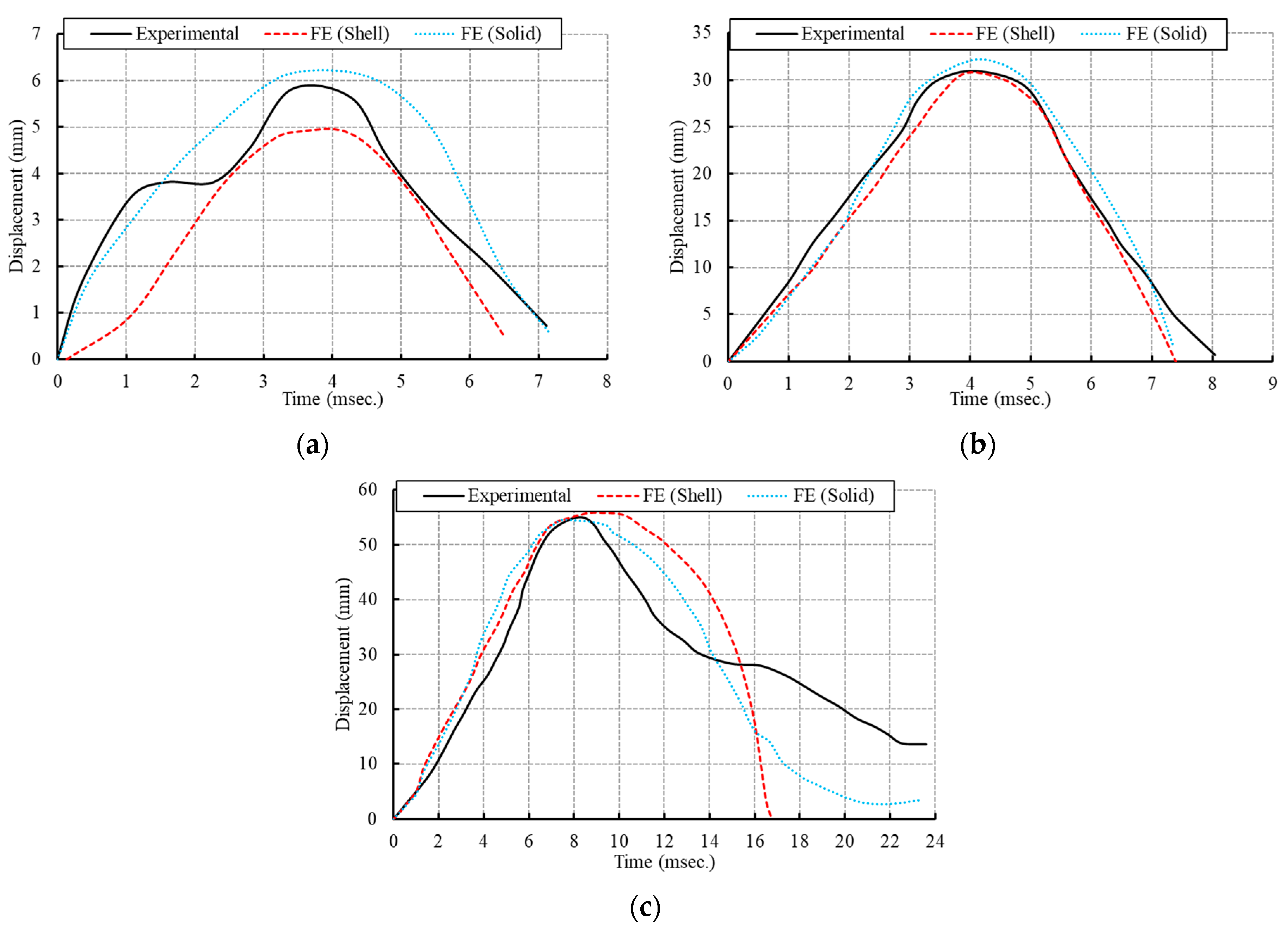
Figure 8 illustrates the mid-span displacement time history, which serves to validate the FE models against the experimental results for the steel columns labeled 1C, 2C, and 3C. Additionally,
Table 3 provides a comprehensive breakdown of the FE model outcomes and compares these findings with experimental data.
Figure 9 provides comparisons between the FE and experimental results in terms of the maximum displacement, maximum strain, and maximum strain rate. The measured peak reflected pressures from the three blast tests, when compared to the FE models with shell elements, deviate by 2.0%, 3.0%, and 16.3% respectively. In contrast, using solid elements in the FE models reduces these discrepancies to 0.7%, 0.2%, and 6.7%, respectively. When evaluating the predicted reflected impulse based on the pressure–time profiles, the FE models using shell elements differ from the experimental values by 8.3%, 2.2%, and 1.6%, respectively. With solid elements, these differences are 6.6%, 2.5%, and 7.0%. The estimated positive phase durations in the FE models vary, with differences ranging between 31.5% and 63.0% when compared to the experimental values. Additionally, for columns exposed to shots 1 and 3, the mid-span strain–time histories have disparities of 0.5% to 59.4% relative to the experimental data. Further comparisons indicate that the maximum displacement differences in the FE models using shell elements are 7%, 0.5%, and 5.7% for columns 1C, 2C, and 3C, respectively. However, these deviations narrow to 4.2%, 1.6%, and 1.2%, respectively, when solid elements are employed in the FE models.
The FE models employing solid elements offer superior computational efficiency compared to those using shell elements. As a result, it is advisable to use fully integrated solid elements, featuring eight integration points on the element surface, in the FE models for accurate predictions of the behavior of PSC under blast loading.
4. Perforated Steel Members
Toughness serves as a crucial indicator for evaluating how PSMs respond to blast events. It can be defined as the capacity of structural components to absorb the energy generated by an explosion and undergo plastic deformation before reaching the point of failure. The value of toughness was determined via the integration of the load–deformation curves up to the failure point. The validated FE models served as tools to analyze the toughness of both PSBs and PSCs in comparison to solid steel beams. The web openings under study encompass various shapes, and are depicted in
Figure 1 and
Figure 2: hexagonal (H), sinusoidal (S), circular (C), and elongated circular (E). We evaluate these opening shapes based on their normalized toughness, taking solid cross-section steel members as the benchmark.
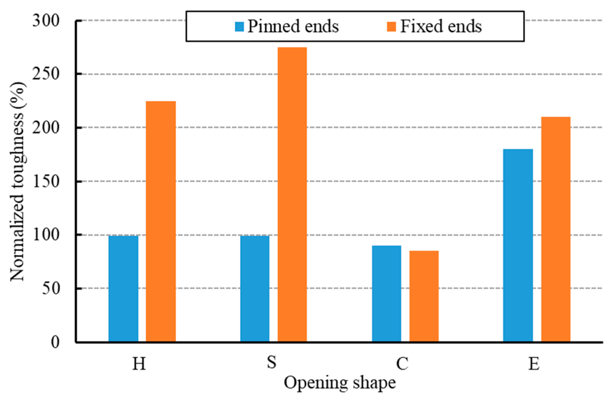
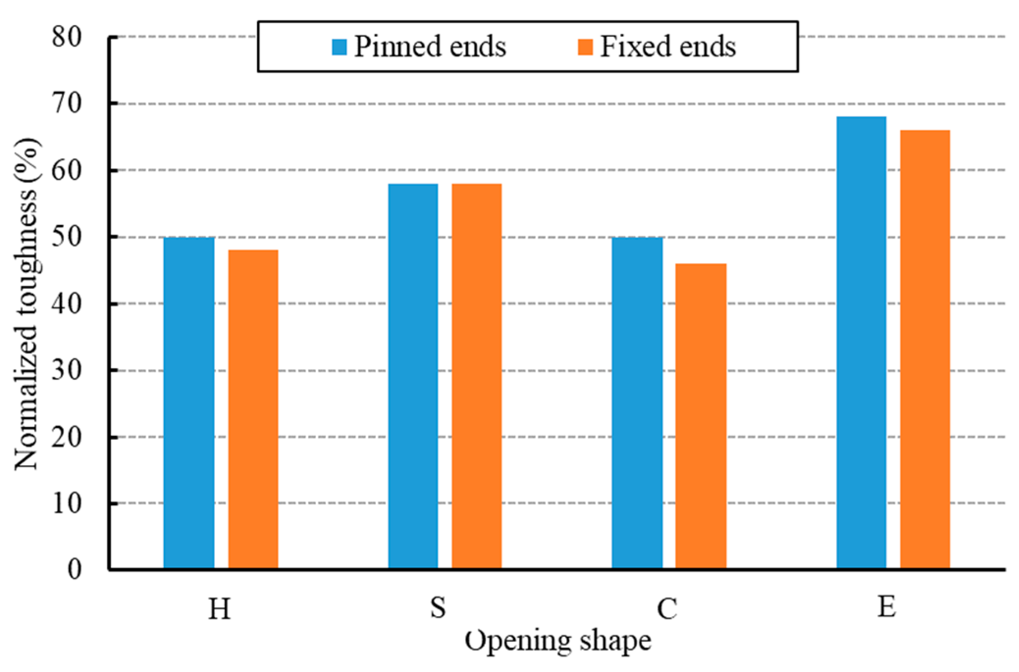
Figure 10 and
Figure 11 specifically showcase the impact of these web opening shapes on the normalized toughness of PSBs and PSCs, respectively.
Beams featuring sinusoidal web openings display superior toughness compared to other shapes when the ends are fixed. This is attributed to the fillets at the corners promoting the even distribution of stress, enhancing their damage resistance. In contrast, beams with elongated circular openings demonstrate peak toughness when the ends are pinned. As the vulnerability spreads between the beam with the most substantial openings and its boundary conditions, there is a rise in the normalized toughness leading up to the point of failure. Conversely, beams with circular web openings register the lowest toughness values. The rationale is twofold: not only do circular openings have the least surface area compared to other shapes, but they also hinder the smooth deformation of the web under blast loading.
Columns with sinusoidal and elongated circular web openings exhibit marginally superior toughness compared to other configurations. This increased resilience is attributed to these particular shapes allowing greater deformation, especially in localized damage areas around the minor axis, preserving residual capacity. Columns with alternative web opening designs show similar toughness values, with minor variations. Overall, the shape of the web opening has a modest influence on the blast resistance of the PSCs.
5. Parametric Study
We have conducted an extensive range of parametric FE simulations to examine PSMs. These PSMs are derived from standard I-beam sections, specifically the W150 × 24, which were modified to feature perforated web sections. These perforations came in varied shapes: hexagonal, circular, sinusoidal, and elongated circular. For retrofitting, we introduced several changes, including closed holes, vertical stiffeners, and spacer plates. Each FE model had a nominal length of 2413 mm, which matches the length used in our validation study. Notably, the introduction of spacer plates resulted in a 40 mm height increase in the perforated section. The sinusoidal openings were innovated by adding a fillet radius of 50 mm to the existing hexagonal openings. This study also considered five different blast scenarios. In the first two blast configurations, the beam and column faced explosive forces of 50 kg and 100 kg, respectively, using ANFO explosives at a standoff distance of 10.3 m. However, in the subsequent scenarios (blast shots #3, #4, and #5), the explosive charges were increased to 150 kg, 200 kg, and 250 kg, with each being detonated at a distance of 9 m. It is significant to note that all these blast pressures, namely BS #1, 3, 4, and 5, targeted the steel member’s strong axis. The only exception was BS #2, which was directed at the weak axis. Furthermore, we analyzed the impact of boundary conditions by providing the perforated steel beams and columns with either pinned or fixed supports.
We have categorized the beams and columns under study using specific parameters for easy identification. Each case is uniquely named, reflecting the element type, web opening shape, blast scenario, boundary conditions, and strengthening details. Element Types: these are distinguished as columns (C) or beams (B). Web Opening Shapes: options include hexagonal holes (H), sinusoidal holes (S), circular holes (C), and elongated circular holes (E). Blast Scenarios: these are denoted by five distinct labels: shot #1 through shot #5. Boundary Conditions: the beams and columns either have pinned (P) or fixed (F) ends. Strengthening varied using different strategies, such as two vertical stiffeners only at ends (Vs), continuous vertical stiffeners (CVs), two closed holes at ends (Ch), and spacer plates (Sp).
5.1. Results and Discussions
We simulated a comprehensive set of FE dynamic models to analyze the dynamic reactions of the beams and columns when subjected to blast load pressures. In the design phase for such blast scenarios, the damage criteria primarily revolve around deformation limits. This is because, for steel members bearing blast-induced loads, the stress rarely surpasses the yielding threshold. As a result, most of the criteria focus on aspects like support rotations and the ductility ratio.
Table 4 gives detailed results for the studied steel columns and beams in both the pinned and fixed ends, respectively. The gauge point is located in the center of each member to measure the displacement–time history. Moreover,
Table 5 lists the damage index and damage levels of the analyzed steel columns.
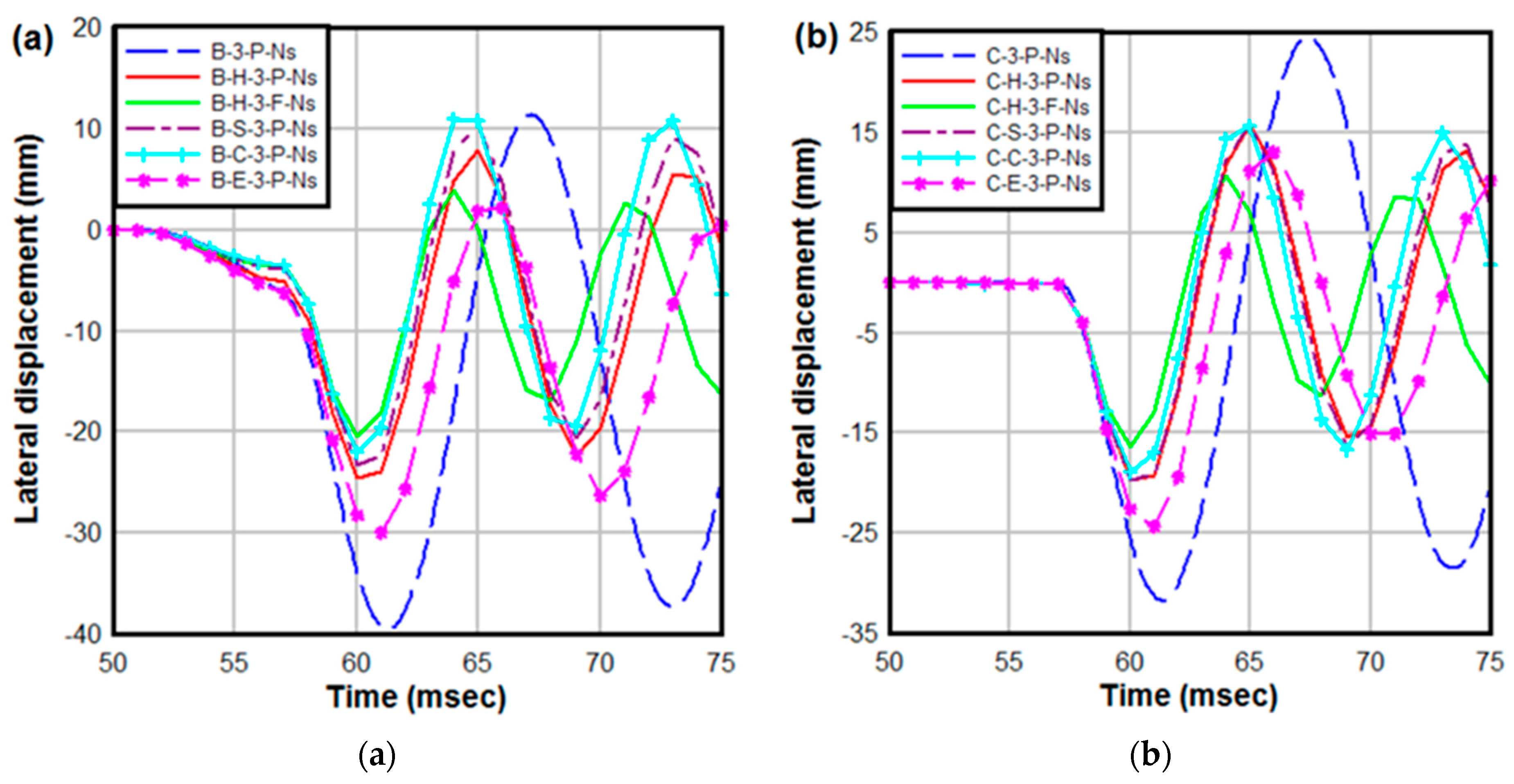
Figure 12 depicts the time histories of lateral displacement for the examined beams and columns. While the castellation technique introduces openings, which can be seen as weak spots in members, it also enhances the member’s shear area and section moment of inertia in the web post. This results in a corresponding increase in the shear and flexural resistance of the PSMs. Members with pinned ends typically exhibit greater maximum displacement than those with fixed ends. As the axial load on the columns grows, there is a sharp rise in the maximum deflection. This increase in deflection stems from the compressive membrane effect, which reduces the column’s deflection in comparison to deflection caused by the gravity-distributed load in the beams.
5.2. Blast Scenarios
The extent of damage to the PSMs is directly influenced by the specifics of the blast. Our findings highlight the significant impact of blast pressure on both the dynamic behavior and the nature of the subsequent failure. Comparisons between the results of different explosion scenarios are listed in
Table 4 and
Table 5 for the two different end conditions. The normalized ductile ratio serves as an effective measure to gauge the efficiency of PSMs relative to their original steel beam counterparts. In BS #1, the ductile ratios typically fall below 1, indicating that the PSMs undergo primarily elastic deformations. However, in subsequent blast shots, the members display signs of yielding and plastic deformation, most prominently at their mid-span sections. The orientation of the steel section relative to the direction of the blast pressure is a crucial factor. Specifically, in BS #2, where the blast is directed at the PSM’s weaker orientation, both the ductility capacities and support rotations are notably higher. This contrasts with members exposed to blasts directed towards their stronger orientation but at comparable scale distances, such as in BS #1 and BS #3.
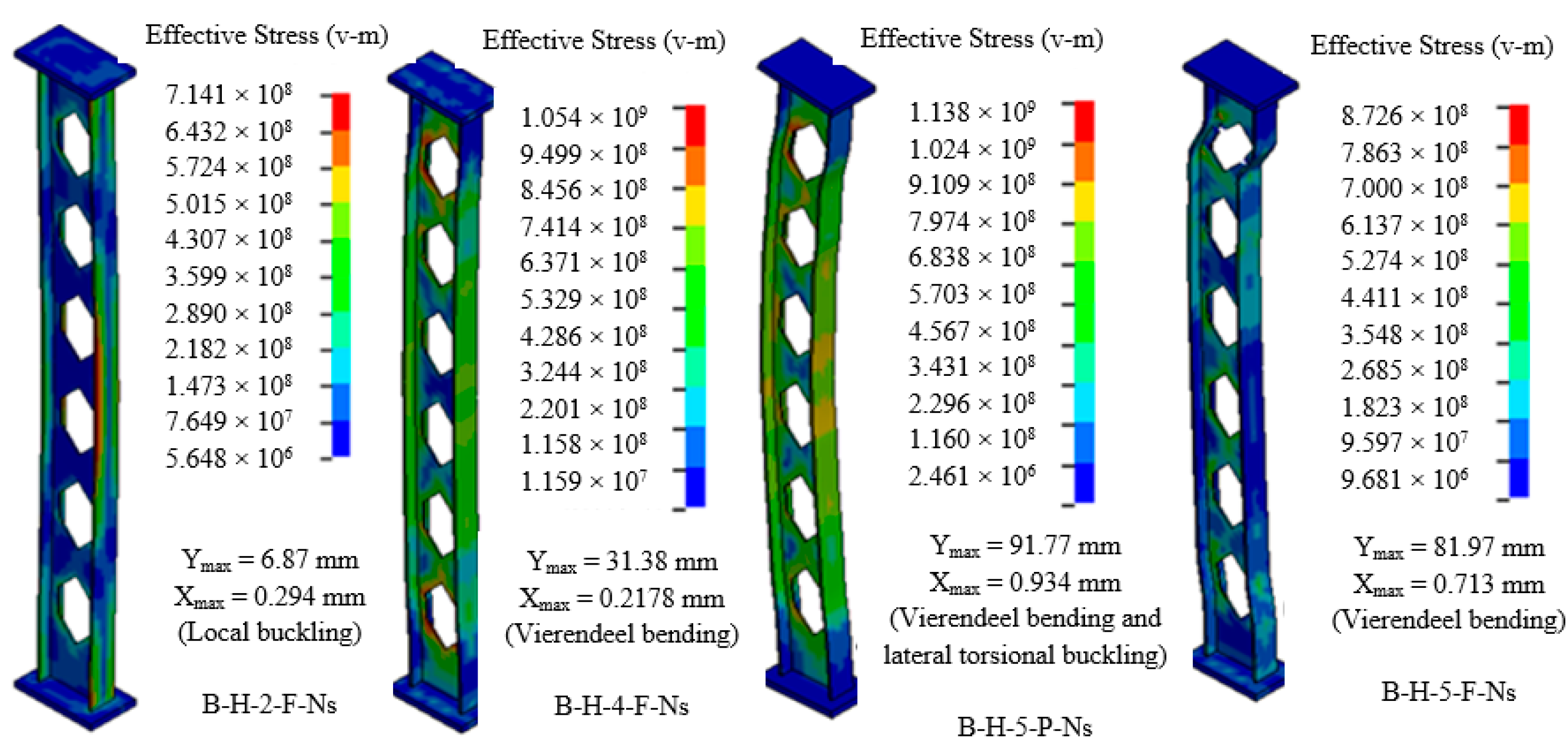
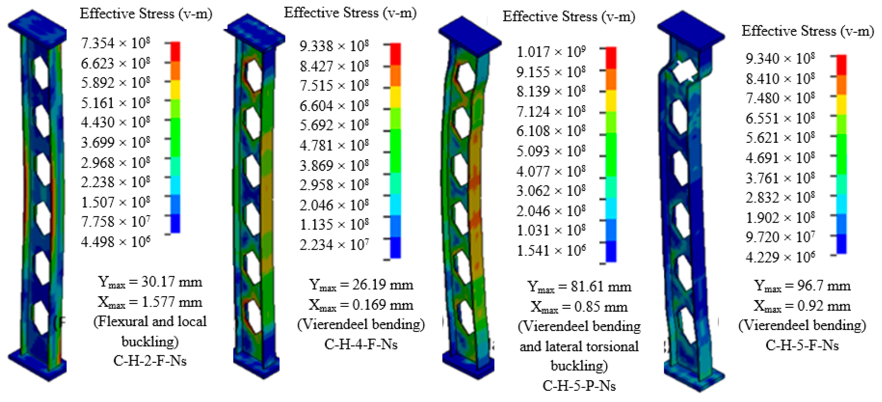
Under BS #2, the PSMs predominantly exhibit a failure mode characterized by web local buckling along the minor axis. In contrast, members subjected to blasts BS #3, BS #4, and BS #5 primarily experience a Vierendeel bending failure, as depicted in
Figure 13 and
Figure 14. These figures further illustrate the transition in the PSMs’ failure mode, moving from flexural damage accompanied by lateral torsional buckling to Vierendeel bending, particularly under blast BS #5, when comparing members with pinned and fixed ends. For the PSCs, the applied axial load induces end movement due to the “P-δ” effect. This movement can accentuate deflection, leading to a swift strength reduction because of buckling. Comparisons between the results of different explosion scenarios are also shown in
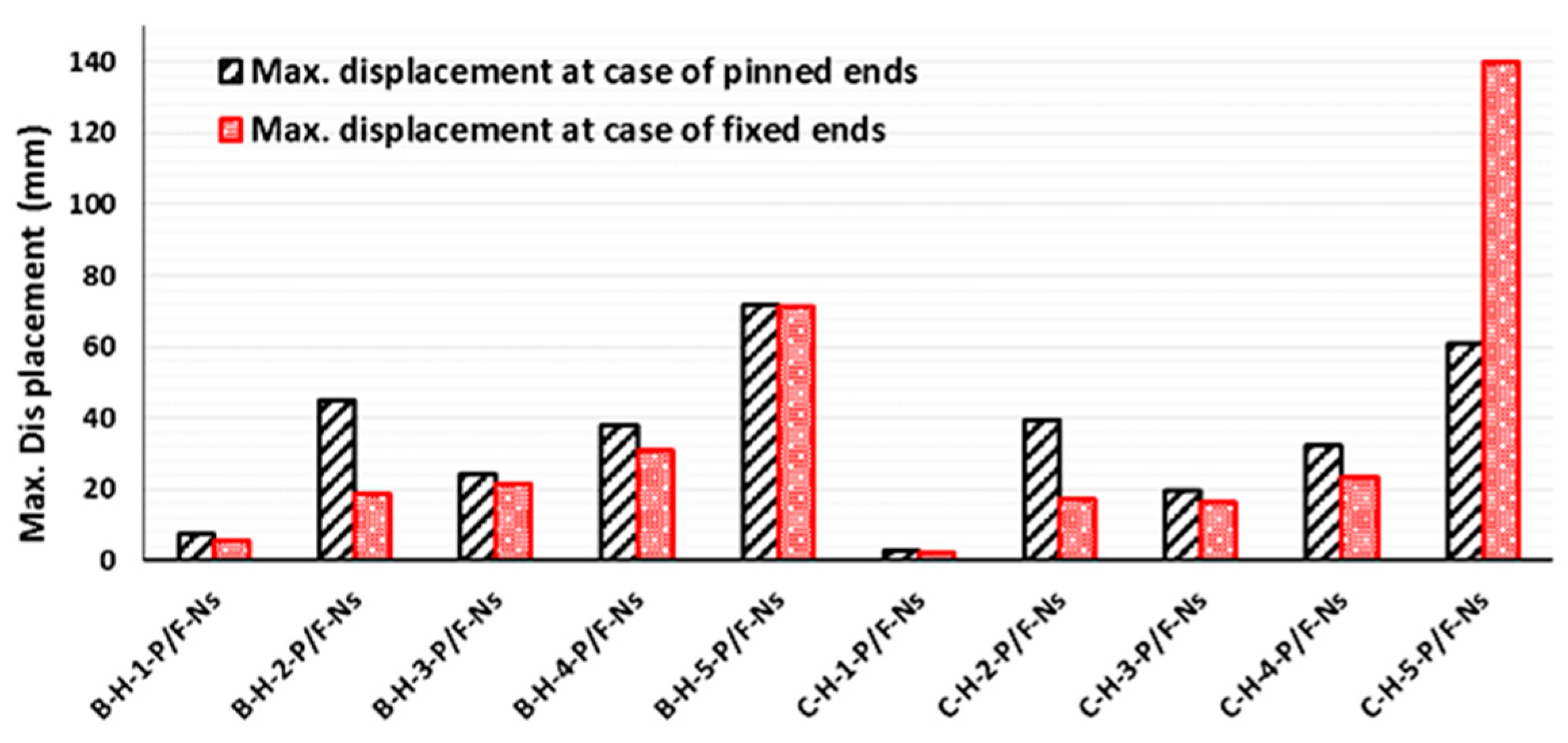
Figure 15 for the two different end conditions.
In the FE analysis, we monitored the maximum deflection up to the point at which the steel flange hits its yield strength. This is because the web’s failure modes enable the member to maintain full resistance under the blast load until the flange fails. To succinctly highlight the influence of each variable, we based our comparisons on the deflection ratio at this failure point between the perforated and original sections.
5.3. Support Conditions
This section examines how boundary conditions influence the likelihood of failure using the displacement criterion.
Figure 15 contrasts the maximum displacements for PSMs with pinned and fixed ends after they have reached the yielding state, under various blast scenarios (BS #1 through BS #5). Transitioning the support conditions from pinned to fixed ends generally results in the damage levels shifting from medium to low post-blast. However, columns with fixed ends show more damage in the most intense scenario, BS #5. This is because the increased axial load amplifies the Vierendeel bending failure near the fixed end. Conversely, PSMs with fixed-fixed boundary conditions fare better compared to their original sections under the transverse blast load of BS #2. For blasts targeting the strong axis (BS #3, #4, and #5), members with pinned ends demonstrate less displacement in comparison to their original section than those with fixed ends. This suggests that pinned ends foster a synergy between the decreased stiffness from web openings and the inherent weakness of such end conditions, preventing abrupt failure, especially under the most severe blasts.
5.4. Web Openings Shapes
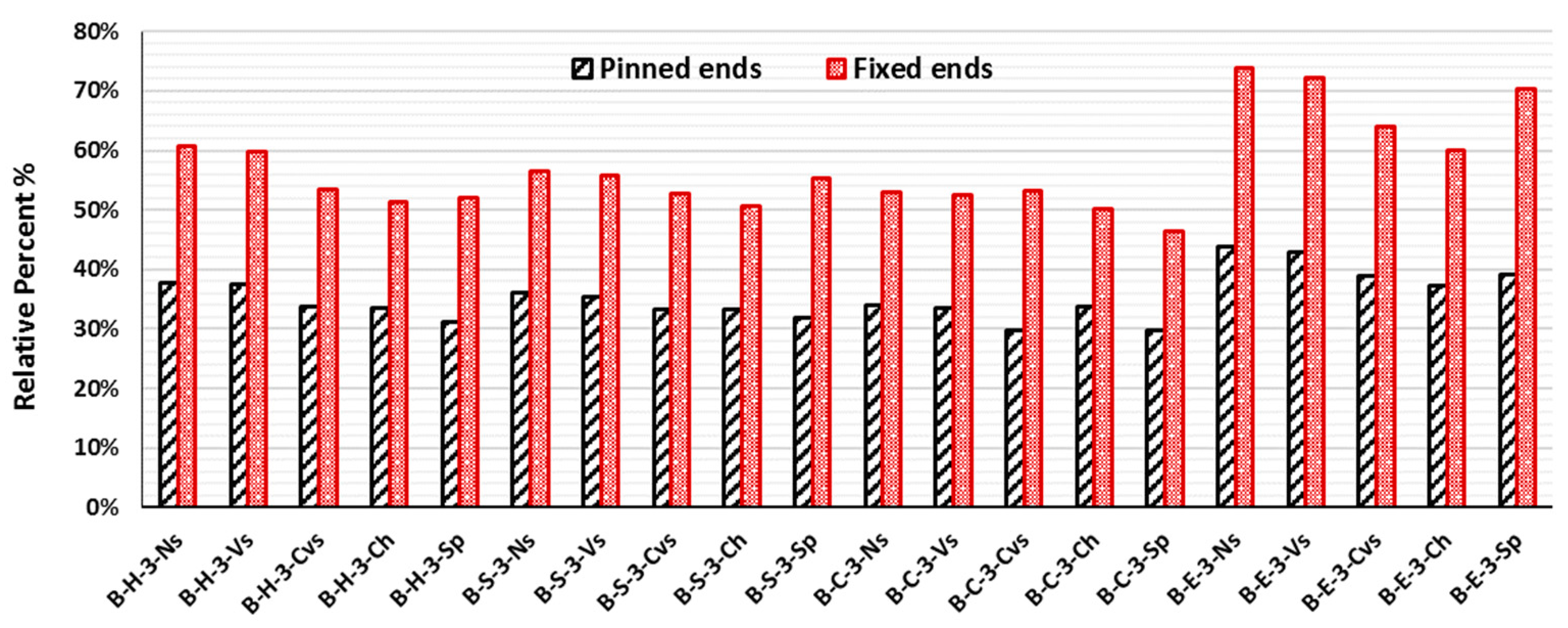
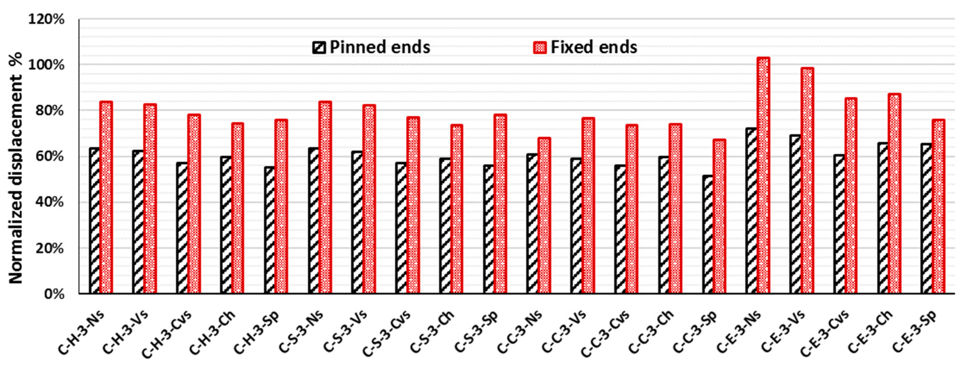
The web opening shapes have a slight effect on the blast resistance of PSMs.
Figure 16 and
Figure 17 demonstrate the effect of the web opening shapes (hexagon, sinusoid, circular, elongated circular) on the behavior of the perforated steel beams and columns, respectively, under BS #3. The members with circular web openings have a slightly higher resistance than other shapes because the fillets at the corners cause smooth stress distribution, allowing damage to be withstood. The members with elongated circular web openings have a smaller resistance than others because the elongated circular web opening has the largest opening area, which causes a remarkable decrease in the member’s strength under the large bending.
5.5. Strengthening Details
The effectiveness of strengthening details depends on the failure modes of the PSMs. The effects of strengthening details on the probability of failure are addressed based on the lateral displacements compared to the PSMs without strengthening. Strengthening the PSMs using continuous vertical stiffeners (CVs) showed significant ductility and gave an increase of up to 45% in columns with fixed ends, as listed in
Table 4 and
Table 5. Meanwhile, strengthening the PSMs using closed holes also gave an increase of up to 33% in the beams with pinned conditions. This result was because strong strengthening helps to promote blast resistance even though it has small deformations. On the contrary, strengthening using the spacer plate had no effect on the ductility in a strong blast because the spacer plate increases the web deformation; this is followed by an increase in the lateral displacement of the total section.
6. Conclusions
In this study, numerical modeling was found to be an economical and safe alternative to experimental work. Furthermore, to replicate real-world situations involving external explosions near steel structures, numerical investigations were conducted to assess the damage resulting from the combined influence of gravity and blast loads. The evaluation of damage for both PSBs and PSCs extends beyond the initial deformation caused by the blast, incorporating residual capacities to establish reliable damage metrics after the explosion. This comprehensive analysis employs explicit finite element simulations using the LSDYNA software.
When compared to experimental data, the finite element model consistently demonstrates a strong alignment with various resistance phases, encompassing bending, softening, and tension membrane regions. This validated numerical model presents a practical substitute for laboratory tests in predicting the dynamic resistance of PSBs and PSCs.
Finite element models utilizing solid elements exhibit enhanced computational efficiency in contrast to those employing shell elements. Therefore, it is recommended that fully integrated solid elements that incorporate eight integration points on the element’s surface are employed in the finite element models to ensure precise predictions of the behavior of PSBs and PSCs under blast loading conditions.
Beams featuring sinusoidal web openings display superior toughness compared to other shapes when the ends are fixed. This is attributed to the fillets at the corners that promote the even distribution of stress, enhancing their damage resistance.
The shape of the web opening has a modest influence on the blast resistance of PSCs.
Retrofitting the PSMs with both closed holes at the end and continuous vertical stiffener provided an obvious increase in the ductility because strong strengthening helps to promote the blast resistance of PSMs, even though they have small deformations.
Author Contributions
Data curation, A.E.-Z. and I.T.A.; Formal analysis, I.T.A.; Investigation, M.T.N.; Methodology, M.T.N., A.E.-Z. and I.T.A.; Resources, A.E.-Z.; Software, I.T.A.; Supervision, M.T.N.; Writing—original draft, M.T.N. and I.T.A.; Writing—review and editing, A.E.-Z. All authors have read and agreed to the published version of the manuscript.
Funding
This research received no external funding.
Data Availability Statement
Data is contained within the article.
Conflicts of Interest
The authors declare no conflict of interest.
References
- Arafa, I.T.; Elhosseiny, O.M.; Nawar, M.T. Damage assessment of perforated steel beams subjected to blast loading. Structures 2022, 40, 646–658. [Google Scholar] [CrossRef]
- Nawar, M.T.; Arafa, I.T.; Elhosseiny, O.M.; El-Zohairy, A. Full static resistance of castellated steel beams with hexagonal web openings for blast response predictions. Eng. Struct. 2021, 245, 112844. [Google Scholar] [CrossRef]
- D’Aniello, M.; Tartaglia, R.; Landolfo, R.; Jaspart, J.-P.; Demonceau, J.-F. Seismic pre-qualification tests of EC8-compliant external extended stiffened end-plate beam-to-column joints. Eng. Struct. 2023, 291, 116386. [Google Scholar] [CrossRef]
- Milone, A.; D’Aniello, M.; Landolfo, R. Influence of camming imperfections on the resistance of lap shear riveted connections. J. Constr. Steel Res. 2023, 203, 107833. [Google Scholar] [CrossRef]
- Cassiano, D.; D’Aniello, M.; Rebelo, C.; Landolfo, R.; Da Silva, L.S. Influence of seismic design rules on the robustness of steel moment resisting frames. Steel Compos. Struct. 2016, 21, 479–500. [Google Scholar] [CrossRef]
- Lee, K.; Kim, T.; Kim, J. Local response of W-shaped steel columns under blast loading. Struct. Eng. Mech. 2009, 31, 25–38. [Google Scholar] [CrossRef]
- Mazurkiewicz, L.; Malachowski, J.; Baranowski, P. Blast loading influence on load carrying capacity of I-column. Eng. Struct. 2015, 104, 107–115. [Google Scholar] [CrossRef]
- Heidarpour, A.; Bradford, M. Beam–column element for non-linear dynamic analysis of steel members subjected to blast loading. Eng. Struct. 2011, 33, 1259–1266. [Google Scholar] [CrossRef]
- Nassr, A.A.; Razaqpur, A.G.; Tait, M.J.; Campidelli, M.; Foo, S. Experimental performance of steel beams under blast loading. J. Perform. Constr. Facil. 2012, 26, 600–619. [Google Scholar] [CrossRef]
- Nassr, A.A.; Razaqpur, A.G.; Tait, M.J.; Campidelli, M.; Foo, S. Single and multi degree of freedom analysis of steel beams under blast loading. Nucl. Eng. Des. 2012, 242, 63–77. [Google Scholar] [CrossRef]
- Nassr, A.A.; Razaqpur, A.G.; Tait, M.J.; Campidelli, M.; Foo, S. Strength and stability of steel beam columns under blast load. Int. J. Impact Eng. 2013, 55, 34–48. [Google Scholar] [CrossRef]
- Nassr, A.A.; Razaqpur, A.G.; Tait, M.J.; Campidelli, M.; Foo, S. Dynamic response of steel columns subjected to blast loading. J. Struct. Eng. 2014, 140, 04014036. [Google Scholar] [CrossRef]
- Shope, R.L. Response of Wide Flange Steel Columns Subjected to Constant Axial Load and Lateral Blast Load; Virginia Tech: Blacksburg, VA, USA, 2006. [Google Scholar]
- LS-DYNA Keyword User’s Manual, Version 971; Livermore Software Technology Corporation: Livermore, CA, USA, 2007.
- Hallquist, J.O. LS-DYNA Theory Manual; Livermore Software Technology Corporation: Livermore, CA, USA, 2006; Volume 3, pp. 25–31. [Google Scholar]
- Cowper, G.R.; Symonds, P.S. Strain-Hardening and Strain-Rate Effects in the Impact Loading of Cantilever Beams; Brown University: Providence, RI, USA, 1957. [Google Scholar]
- Haufe, A.; Schweizerhof, K.; DuBois, P. Properties & Limits: Review of Shell Element Formulations; Developer Forum DYNA More: Filderstadt, Germany, 2013. [Google Scholar]
- Erhart, T. Review of solid element formulations in LS-DYNA: Properties, limits, advantages, disadvantages. In Proceedings of the LS-DYNA Developers’ Forum; Gesellschaft für FEM Ingenieurdienstleistungen mbH: Stuttgart, Germany, 2011; pp. 12–13. [Google Scholar]
- Tsavdaridis, K.; Mello, C.D. Finite element investigation of perforated steel beams with different web opening configurations. In Proceedings of the Sixth International Conference on Advances in Steel Structures and Progress in Structural Stability and Dynamics, ICASS’09/IJSSD, Hong Kong, China, 16–18 December 2009; pp. 213–220. [Google Scholar]
- Liu, T.; Chung, K. Steel beams with large web openings of various shapes and sizes: Finite element investigation. Constr. Steel Res. 2003, 59, 1159–1176. [Google Scholar] [CrossRef]
- Nawar, M.T.; Arafa, I.T.; Elhosseiny, O. Numerical investigation on effective spans ranges of perforated steel beams. Structures 2020, 25, 398–410. [Google Scholar] [CrossRef]
- Nawar, M.T.; Arafa, I.T.; Elhosseiny, O.M. Numerical damage evaluation of perforated steel columns subjected to blast loading. Def. Technol. 2022, 18, 735–746. [Google Scholar] [CrossRef]
- Shi, Y.; Hao, H.; Li, Z.-X. Numerical derivation of pressure–impulse diagrams for prediction of RC column damage to blast loads. Int. J. Impact Eng. 2008, 35, 1213–1227. [Google Scholar] [CrossRef]
- Shi, Y.; Stewart, M.G. Spatial reliability analysis of explosive blast load damage to reinforced concrete columns. Struct. Saf. 2015, 53, 13–25. [Google Scholar] [CrossRef]
- Bao, X.; Li, B. Residual strength of blast damaged reinforced concrete columns. Int. J. Impact Eng. 2010, 37, 295–308. [Google Scholar] [CrossRef]
- Bounds, W.L. Design of Blast-Resistant Buildings in Petrochemical Facilities; ASCE Publications: Reston, VA, USA, 2010. [Google Scholar]
- US DoD. Structures to Resist the Effects of Accidental Explosions; UFC 3-340-02; US DoD: Washington, DC, USA, 2014. [Google Scholar]
- Zhang, C.; Gholipour, G.; Mousavi, A.A. Nonlinear dynamic behavior of simply-supported RC beams subjected to combined impact-blast loading. Eng. Struct. 2019, 181, 124–142. [Google Scholar] [CrossRef]
Figure 1.
Schematic diagrams illustrating the simulated PSBs with various web opening designs subjected to blast loading, under either pinned or fixed conditions [
1].
Figure 1.
Schematic diagrams illustrating the simulated PSBs with various web opening designs subjected to blast loading, under either pinned or fixed conditions [
1].
Figure 2.
A schematic representation for the simulated PSCs with different web opening shapes [
22].
Figure 2.
A schematic representation for the simulated PSCs with different web opening shapes [
22].
Figure 3.
Illustration of the blast loading profile.
Figure 3.
Illustration of the blast loading profile.
Figure 4.
Schematic illustration of the loading method used to assess the post-blast residual capacity of the studied steel beams [
1].
Figure 4.
Schematic illustration of the loading method used to assess the post-blast residual capacity of the studied steel beams [
1].
Figure 5.
Schematic depiction of the loading method used to assess the post-blast residual capacity of the analyzed PSCs [
22].
Figure 5.
Schematic depiction of the loading method used to assess the post-blast residual capacity of the analyzed PSCs [
22].
Figure 6.
Comparisons of mid-span displacement time histories between the FE and experimental results for the analyzed PSBs. (a) Specimen 1B. (b) Specimen 2B. (c) Specimen 3B.
Figure 6.
Comparisons of mid-span displacement time histories between the FE and experimental results for the analyzed PSBs. (a) Specimen 1B. (b) Specimen 2B. (c) Specimen 3B.
Figure 7.
Comparisons between the FE and experimental findings for the analyzed PSBs. (a) Maximum displacement. (b) Maximum strain. (c) Maximum strain rate.
Figure 7.
Comparisons between the FE and experimental findings for the analyzed PSBs. (a) Maximum displacement. (b) Maximum strain. (c) Maximum strain rate.
Figure 8.
The mid-span displacement time histories obtained from the FE model align with the experimental findings for the analyzed PSCs. (a) Specimen 1C. (b) Specimen 2C. (c) Specimen 3C.
Figure 8.
The mid-span displacement time histories obtained from the FE model align with the experimental findings for the analyzed PSCs. (a) Specimen 1C. (b) Specimen 2C. (c) Specimen 3C.
Figure 9.
Comparisons between the FE and experimental results for the analyzed PSCs. (a) Maximum displacement. (b) Maximum strain. (c) Maximum strain rate.
Figure 9.
Comparisons between the FE and experimental results for the analyzed PSCs. (a) Maximum displacement. (b) Maximum strain. (c) Maximum strain rate.
Figure 10.
Normalized toughness results for PSBs with different web opening shapes.
Figure 10.
Normalized toughness results for PSBs with different web opening shapes.
Figure 11.
Normalized toughness results for PSCs with different web opening shapes.
Figure 11.
Normalized toughness results for PSCs with different web opening shapes.
Figure 12.
The lateral displacement time histories at the mid-span section under blast shot BS #3. (a) PSBs. (b) PSCs.
Figure 12.
The lateral displacement time histories at the mid-span section under blast shot BS #3. (a) PSBs. (b) PSCs.
Figure 13.
Von Mises stresses in the PSBs.
Figure 13.
Von Mises stresses in the PSBs.
Figure 14.
Von Mises stresses in the PSCs.
Figure 14.
Von Mises stresses in the PSCs.
Figure 15.
Ultimate displacements of the PSMs with pinned and fixed ends under different blast shots.
Figure 15.
Ultimate displacements of the PSMs with pinned and fixed ends under different blast shots.
Figure 16.
Lateral displacement of perforated steel beams normalized to its parent section with different web opening shapes under BS #3.
Figure 16.
Lateral displacement of perforated steel beams normalized to its parent section with different web opening shapes under BS #3.
Figure 17.
Lateral displacement of perforated steel columns normalized to its parent section with different web opening shapes under BS #3.
Figure 17.
Lateral displacement of perforated steel columns normalized to its parent section with different web opening shapes under BS #3.
Table 1.
Deformation criteria for steel structural members according to UFC [
27].
Table 1.
Deformation criteria for steel structural members according to UFC [
27].
| Damage Criteria | Steel Primary Frame Members | Damage Levels |
|---|
| Low | Moderate | High | Hazardous |
|---|
- 1-
Support rotation
| Member without significant compression load *
Member with significant
compression load * | 1°
1° | 2°
1.5° | 4°
2° | 12° |
- 2-
Ductility ratio
| All members | <1 | 3 | 10 | 20 |
Table 2.
Comparisons between the FE and experimental findings.
Table 2.
Comparisons between the FE and experimental findings.
| Tested Specimens | Z (m/kg1/3) | Results | Pr (kPa) | Ir (kPa.msec) | td (msec) | Umax (mm) | εmax (με) | Sr (s-1) |
|---|
| 1B | 2.8 | Experimental | 307 | 715 | 7.3 | 6.8 | 559 | 0.28 |
| FE (Shell) | 313 | 774.7 | 9.7 | 6.5 | 578.6 | 0.33 |
| FE (Solid) | 309 | 762 | 9.6 | 6.8 | 566.7 | 0.32 |
| 2B | 2.22 | Experimental | 623 | 1279 | 6 | 40.9 | 3435 | 0.9 |
| FE (Shell) | 604 | 1307 | 9.5 | 41.8 | 2206 | 0.75 |
| FE (Solid) | 622 | 1311 | 9.6 | 41.1 | 1872 | 0.98 |
| 3B | 1.69 | Experimental | 1560 | 2130 | 6.2 | 32.5 | 2384 | 1.7 |
| FE (Shell) | 1306 | 2095.2 | 10.1 | 31.1 | 2599 | 2.01 |
| FE (Solid) | 1455 | 2278.8 | 10 | 32.2 | 2564 | 1.71 |
Table 3.
The detailed results of the FE models for the analyzed PSCs.
Table 3.
The detailed results of the FE models for the analyzed PSCs.
| Z (m/kg1/3) | Measurements | Pr (kPa) | Ir (kPa.msec) | Td
(msec) | Tested Specimens | Umax
(mm) | εmax
(με) | Srmax
(s-1) |
|---|
| 2.8 | Experimental | 307 | 715 | 7.3 | 1C | 5.87 | 420 | 0.22 |
| FE (Shell) | 313 | 774.7 | 9.7 | 5.458 | 448 | 0.3 |
| FE (Solid) | 309 | 762 | 9.6 | 6.114 | 400 | 0.26 |
| 2.22 | Experimental | 623 | 1279 | 6 | 2C | 55.35 | 2420 | 1.5 |
| FE (Shell) | 604 | 1307 | 9.5 | 55.61 | 2200 | 1.7 |
| FE (Solid) | 622 | 1311 | 9.6 | 54.48 | 2340 | 1.30 |
| 1.69 | Experimental | 1560 | 2130 | 6.2 | 3C | 31.13 | 2000 | 1.5 |
| FE (Shell) | 1306 | 2095.2 | 10.1 | 29.37 | 2010 | 1.25 |
| FE (Solid) | 1455 | 2278.8 | 10 | 31.51 | 2307 | 2 |
Table 4.
Displacement criteria of examined PSMs.
Table 4.
Displacement criteria of examined PSMs.
| | Pinned Ends | Fixed Ends |
|---|
Scaled Distance, Z
(m/kg1/3) | Columns | Support Rotation, θ | Ductility Ratio, μ | Beams | Support Rotation, θ | Ductility Ratio, μ | Columns | Support Rotation, θ | Ductility Ratio, μ | Beams | Support Rotation, θ | Ductility Ratio, μ |
|---|
| 2.8 | C-1-P-Ns | 0.28 | <1 | B-1-P-Ns | 1.24 | 1.35 | C-1-F-Ns | 0.16 | <1 | B-1-F-Ns | 0.84 | <1 |
| C-H-1-P-Ns | 0.13 | <1 | B-H-1-P-Ns | 0.35 | <1 | C-H-1-F-Ns | 0.10 | <1 | B-H-1-F-Ns | 0.25 | <1 |
| C-H-1-P-Vs | 0.13 | <1 | B-H-1-P-Vs | 0.33 | <1 | C-H-1-F-Vs | 0.10 | <1 | B-H-1-F-Vs | 0.25 | <1 |
| C-H-1-P-Cvs | 0.11 | <1 | B-H-1-P-Cvs | 0.26 | <1 | C-H-1-F-Cvs | 0.09 | <1 | B-H-1-F-Cvs | 0.25 | <1 |
| C-H-1-P-Ch | 0.11 | <1 | B-H-1-P-Ch | 0.26 | <1 | C-H-1-F-Ch | 0.03 | <1 | B-H-1-F-Ch | 0.18 | <1 |
| C-H-1-P-Sp | 0.10 | <1 | B-H-1-P-Sp | 0.21 | <1 | C-H-1-F-Sp | 0.07 | <1 | B-H-1-F-Sp | 0.18 | <1 |
| 2.22 | C-2-P-Ns | 1.86 | 2.27 | B-2-P-Ns | 2.14 | 2.32 | C-2-F-Ns | 1.09 | 1.78 | B-2-F-Ns | 1.11 | 1.48 |
| C-H-2-P-Ns | 1.82 | 2.47 | B-H-2-P-Ns | 2.10 | 2.13 | C-H-2-F-Ns | 0.82 | 1.52 | B-H-2-F-Ns | 0.90 | 1.32 |
| C-H-2-P-Vs | 1.80 | 3.60 | B-H-2-P-Vs | 2.07 | 1.98 | C-H-2-F-Vs | 0.67 | 1.15 | B-H-2-F-Vs | 0.86 | 1.16 |
| C-H-2-P-Cvs | 1.70 | 2.43 | B-H-2-P-Cvs | 1.03 | 1.57 | C-H-2-F-Cvs | 1.03 | 1.74 | B-H-2-F-Cvs | 1.01 | 1.31 |
| C-H-2-P-Ch | 1.93 | 2.45 | B-H-2-P-Ch | 2.29 | 2.13 | C-H-2-F-Ch | 1.08 | 2.35 | B-H-2-F-Ch | 1.01 | 1.34 |
| C-H-2-P-Sp | 1.81 | 2.30 | B-H-2-P-Sp | 2.23 | 1.67 | C-H-2-F-Sp | 0.76 | 1.12 | B-H-2-F-Sp | 1.03 | 1.24 |
| 1.69 | C-3-P-Ns | 1.48 | 2.31 | B-3-P-Ns | 3.06 | 3.32 | C-3-F-Ns | 0.93 | 1.56 | B-3-F-Ns | 1.69 | 2.09 |
| C-H-3-P-Ns | 0.94 | 2.12 | B-H-3-P-Ns | 1.15 | 1.73 | C-H-3-F-Ns | 0.78 | 1.87 | B-H-3-F-Ns | 1.03 | 1.51 |
| C-H-3-P-Vs | 0.92 | 2.35 | B-H-3-P-Vs | 1.14 | 1.70 | C-H-3-F-Vs | 0.77 | 2.15 | B-H-3-F-Vs | 1.01 | 1.47 |
| C-H-3-P-Cvs | 0.84 | 1.90 | B-H-3-P-Cvs | 1.03 | 1.57 | C-H-3-F-Cvs | 0.73 | 1.78 | B-H-3-F-Cvs | 0.91 | 1.38 |
| C-H-3-P-Ch | 0.88 | 2.59 | B-H-3-P-Ch | 1.03 | 1.74 | C-H-3-F-Ch | 0.69 | 2.36 | B-H-3-F-Ch | 0.87 | 1.52 |
| C-H-3-P-Sp | 0.82 | 1.99 | B-H-3-P-Sp | 0.95 | 1.53 | C-H-3-F-Sp | 0.71 | 1.74 | B-H-3-F-Sp | 0.88 | 1.35 |
| C-S-3-P-Ns | 0.94 | 1.90 | B-S-3-P-Ns | 1.10 | 1.62 | C-S-3-F-Ns | 0.78 | 1.90 | B-S-3-F-Ns | 0.96 | 1.37 |
| C-S-3-P-Vs | 0.92 | 2.04 | B-S-3-P-Vs | 1.08 | 1.57 | C-S-3-F-Vs | 0.76 | 1.74 | B-S-3-F-Vs | 0.94 | 1.34 |
| C-S-3-P-Cvs | 0.84 | 1.80 | B-S-3-P-Cvs | 1.02 | 1.53 | C-S-3-F-Cvs | 0.72 | 1.62 | B-S-3-F-Cvs | 0.89 | 1.32 |
| C-S-3-P-Ch | 0.87 | 2.62 | B-S-3-P-Ch | 1.02 | 1.72 | C-S-3-F-Ch | 0.68 | 2.37 | B-S-3-F-Ch | 0.86 | 1.49 |
| C-S-3-P-Sp | 0.83 | 1.90 | B-S-3-P-Sp | 0.97 | 1.48 | C-S-3-F-Sp | 0.73 | 1.65 | B-S-3-F-Sp | 0.94 | 1.24 |
| C-C-3-P-Ns | 0.90 | 2.26 | B-C-3-P-Ns | 1.04 | 1.59 | C-C-3-F-Ns | 0.63 | 1.67 | B-C-3-F-Ns | 0.90 | 1.37 |
| C-C-3-P-Vs | 0.87 | 2.06 | B-C-3-P-Vs | 1.03 | 1.58 | C-C-3-F-Vs | 0.71 | 1.82 | B-C-3-F-Vs | 0.89 | 1.37 |
| C-C-3-P-Cvs | 0.83 | 1.83 | B-C-3-P-Cvs | 0.91 | 1.40 | C-C-3-F-Cvs | 0.68 | 1.64 | B-C-3-F-Cvs | 0.90 | 1.40 |
| C-C-3-P-Ch | 0.88 | 2.36 | B-C-3-P-Ch | 1.03 | 1.63 | C-C-3-F-Ch | 0.69 | 2.08 | B-C-3-F-Ch | 0.85 | 1.38 |
| C-C-3-P-Sp | 0.76 | 1.91 | B-C-3-P-Sp | 0.91 | 1.53 | C-C-3-F-Sp | 0.63 | 1.64 | B-C-3-F-Sp | 0.79 | 1.28 |
| C-E-3-P-Ns | 1.07 | 2.27 | B-E-3-P-Ns | 1.34 | 1.71 | C-E-3-F-Ns | 0.96 | 2.00 | B-E-3-F-Ns | 1.25 | 1.46 |
| C-E-3-P-Vs | 1.02 | 2.39 | B-E-3-P-Vs | 1.31 | 1.67 | C-E-3-F-Vs | 0.92 | 2.13 | B-E-3-F-Vs | 1.22 | 1.42 |
| C-E-3-P-Cvs | 0.89 | 1.70 | B-E-3-P-Cvs | 1.19 | 1.55 | C-E-3-F-Cvs | 0.79 | 1.61 | B-E-3-F-Cvs | 1.08 | 1.28 |
| C-E-3-P-Ch | 0.97 | 2.83 | B-E-3-P-Ch | 1.14 | 1.82 | C-E-3-F-Ch | 0.81 | 2.82 | B-E-3-F-Ch | 1.02 | 1.64 |
| C-E-3-P-Sp | 0.96 | 2.20 | B-E-3-P-Sp | 1.20 | 1.54 | C-E-3-F-Sp | 0.71 | 1.56 | B-E-3-F-Sp | 1.19 | 1.34 |
| 1.43 | C-4-P-Ns | 2.49 | 3.39 | B-4-P-Ns | 5.68 | 6.25 | C-4-F-Ns | 1.51 | 2.60 | B-4-F-Ns | 2.43 | 3.05 |
| C-H-4-P-Ns | 1.52 | 2.99 | B-H-4-P-Ns | 1.80 | 2.78 | C-H-4-F-Ns | 1.11 | 2.26 | B-H-4-F-Ns | 1.46 | 2.20 |
| C-H-4-P-Vs | 1.52 | 3.23 | B-H-4-P-Vs | 1.77 | 2.70 | C-H-4-F-Vs | 1.09 | 2.55 | B-H-4-F-Vs | 1.44 | 2.12 |
| C-H-4-P-Cvs | 1.45 | 3.20 | B-H-4-P-Cvs | 1.63 | 2.50 | C-H-4-F-Cvs | 1.14 | 2.71 | B-H-4-F-Cvs | 1.31 | 1.98 |
| C-H-4-P-Ch | 1.37 | 3.04 | B-H-4-P-Ch | 1.54 | 2.67 | C-H-4-F-Ch | 0.81 | 2.04 | B-H-4-F-Ch | 1.01 | 1.87 |
| C-H-4-P-Sp | 1.22 | 2.53 | B-H-4-P-Sp | 1.39 | 2.20 | C-H-4-F-Sp | 0.97 | 2.03 | B-H-4-F-Sp | 1.24 | 1.87 |
| 1.11 | C-5-P-Ns | 6.10 | 12.78 | B-5-P-Ns | 10.05 | 8.92 | C-5-F-Ns | 4.14 | 8.81 | B-5-F-Ns | 5.35 | 21.88 |
| C-H-5-P-Ns | 2.89 | 3.78 | B-H-5-P-Ns | 1.80 | 3.34 | C-H-5-F-Ns | 6.62 | 8.45 | B-H-5-F-Ns | 1.77 | 3.08 |
| C-H-5-P-Vs | 2.85 | 7.41 | B-H-5-P-Vs | 1.77 | 3.42 | C-H-5-F-Vs | 7.04 | 9.50 | B-H-5-F-Vs | 1.77 | 3.02 |
| C-H-5-P-Cvs | 2.55 | 6.08 | B-H-5-P-Cvs | 1.77 | 5.33 | C-H-5-F-Cvs | 2.15 | 4.99 | B-H-5-F-Cvs | 1.77 | 4.17 |
| C-H-5-P-Ch | 3.35 | 4.59 | B-H-5-P-Ch | 1.77 | 3.85 | C-H-5-F-Ch | 2.55 | 3.53 | B-H-5-F-Ch | 1.01 | 2.76 |
| C-H-5-P-Sp | 5.91 | 7.71 | B-H-5-P-Sp | 1.77 | 3.02 | C-H-5-F-Sp | 5.77 | 7.38 | B-H-5-F-Sp | 1.24 | 1.55 |
Table 5.
The damage index and damage levels of the examined steel columns with pinned and fixed ends.
Table 5.
The damage index and damage levels of the examined steel columns with pinned and fixed ends.
| | Pinned Ends | Fixed Ends |
|---|
Scaled Distance, Z
(m/kg1/3) | Columns | P Initial
(KN) | P Residual
(KN) | D | Damage Level | Columns | P initial
(KN) | P residual
(KN) | D | Damage Level |
|---|
| 2.8 | C-1-P-Ns | 1470.6 | 1219.8 | 0.17 | Low Damage | C-1-F-Ns | 2195.1 | 1973.7 | 0.10 | Low Damage |
| C-H-1-P-Ns | 1464.7 | 1428.4 | 0.02 | Low Damage | C-H-1-F-Ns | 1870.9 | 1688.3 | 0.10 | Low Damage |
| C-H-1-P-Vs | 1533.3 | 1438.2 | 0.06 | Low Damage | C-H-1-F-Vs | 1912.8 | 1704.4 | 0.11 | Low Damage |
| C-H-1-P-Cvs | 1607.6 | 1451.2 | 0.10 | Low Damage | C-H-1-F-Cvs | 1916 | 1760.7 | 0.08 | Low Damage |
| C-H-1-P-Ch | 1500.4 | 1445 | 0.04 | Low Damage | C-H-1-F-Ch | 1870.1 | 1743.5 | 0.07 | Low Damage |
| C-H-1-P-Sp | 1495.7 | 1433.7 | 0.04 | Low Damage | C-H-1-F-Sp | 1860.1 | 1741.7 | 0.06 | Low Damage |
| 2.22 | C-2-P-Ns | 1470.6 | 994.15 | 0.32 | Medium Damage | C-2-F-Ns | 2195.1 | 1847 | 0.16 | Low Damage |
| C-H-2-P-Ns | 1464.7 | 994.15 | 0.32 | Medium Damage | C-H-2-F-Ns | 1870.9 | 1600.1 | 0.14 | Low Damage |
| C-H-2-P-Vs | 1533.3 | 1068.4 | 0.30 | Medium Damage | C-H-2-F-Vs | 1912.8 | 1599.9 | 0.16 | Low Damage |
| C-H-2-P-Cvs | 1607.6 | 1096.2 | 0.32 | Medium Damage | C-H-2-F-Cvs | 1916 | 1635.6 | 0.14 | Low Damage |
| C-H-2-P-Ch | 1500.4 | 982.93 | 0.34 | Medium Damage | C-H-2-F-Ch | 1870.1 | 1556.7 | 0.17 | Low Damage |
| C-H-2-P-Sp | 1495.7 | 1055.3 | 0.29 | Medium Damage | C-H-2-F-Sp | 1860.1 | 1589.8 | 0.15 | Low Damage |
| 1.69 | C-3-P-Ns | 1470.6 | 1207.6 | 0.18 | Low Damage | C-3-F-Ns | 2195.1 | 1947.5 | 0.11 | Low Damage |
| C-H-3-P-Ns | 1464.7 | 1273.6 | 0.13 | Low Damage | C-H-3-F-Ns | 1870.9 | 1689.3 | 0.10 | Low Damage |
| C-H-3-P-Vs | 1533.3 | 1347.3 | 0.12 | Low Damage | C-H-3-F-Vs | 1912.8 | 1756 | 0.08 | Low Damage |
| C-H-3-P-Cvs | 1607.6 | 1344.7 | 0.16 | Low Damage | C-H-3-F-Cvs | 1916 | 1705.5 | 0.11 | Low Damage |
| C-H-3-P-Ch | 1500.4 | 1298.2 | 0.13 | Low Damage | C-H-3-F-Ch | 1870.1 | 1705.5 | 0.09 | Low Damage |
| C-H-3-P-Sp | 1495.7 | 1317.6 | 0.12 | Low Damage | C-H-3-F-Sp | 1860.1 | 1687.7 | 0.09 | Low Damage |
| C-S-3-P-Ns | 1509.7 | 1240 | 0.18 | Low Damage | C-S-3-F-Ns | 1874.9 | 1689.9 | 0.10 | Low Damage |
| C-S-3-P-Vs | 1511.7 | 1296.7 | 0.14 | Low Damage | C-S-3-F-Vs | 1925.8 | 1678.4 | 0.13 | Low Damage |
| C-S-3-P-Cvs | 1689.7 | 1347.2 | 0.20 | Low Damage | C-S-3-F-Cvs | 1876.9 | 1426.3 | 0.08 | Low Damage |
| C-S-3-P-Ch | 1597.6 | 1326.6 | 0.17 | Low Damage | C-S-3-F-Ch | 1915 | 1726.7 | 0.10 | Low Damage |
| C-S-3-P-Sp | 1600.4 | 1481.2 | 0.07 | Low Damage | C-S-3-F-Sp | 1890.7 | 1687.4 | 0.11 | Low Damage |
| C-C-3-P-Ns | 1464.7 | 1311.4 | 0.10 | Low Damage | C-C-3-F-Ns | 1871.5 | 1736.7 | 0.07 | Low Damage |
| C-C-3-P-Vs | 1463.5 | 1327.6 | 0.09 | Low Damage | C-C-3-F-Vs | 1927.7 | 1759.7 | 0.09 | Low Damage |
| C-C-3-P-Cvs | 1565 | 1341.2 | 0.14 | Low Damage | C-C-3-F-Cvs | 1950.8 | 1803.5 | 0.08 | Low Damage |
| C-C-3-P-Ch | 1660 | 1450 | 0.13 | Low Damage | C-C-3-F-Ch | 2994.5 | 2430 | 0.19 | Low Damage |
| C-C-3-P-Sp | 1495.8 | 1398.3 | 0.07 | Low Damage | C-C-3-F-Sp | 1928.8 | 1680.1 | 0.13 | Low Damage |
| C-E-3-P-Ns | 1530.4 | 1227 | 0.20 | Low Damage | C-E-3-F-Ns | 1863 | 1643.2 | 0.12 | Low Damage |
| C-E-3-P-Vs | 1528.3 | 1311 | 0.14 | Low Damage | C-E-3-F-Vs | 1859 | 1738.4 | 0.06 | Low Damage |
| C-E-3-P-Cvs | 1604.3 | 1290.8 | 0.20 | Low Damage | C-E-3-F-Cvs | 1919.4 | 1701.4 | 0.11 | Low Damage |
| C-E-3-P-Ch | 1584.5 | 1325.8 | 0.16 | Low Damage | C-E-3-F-Ch | 1923.1 | 1731 | 0.10 | Low Damage |
| C-E-3-P-Sp | 1588.3 | 1364.6 | 0.14 | Low Damage | C-E-3-F-Sp | 1856.9 | 1687.7 | 0.09 | Low Damage |
| 1.43 | C-4-P-Ns | 1470.6 | 1158.4 | 0.21 | Medium Damage | C-4-F-Ns | 2195.1 | 1942.6 | 0.12 | Low Damage |
| C-H-4-P-Ns | 1464.7 | 1231.6 | 0.16 | Low Damage | C-H-4-F-Ns | 1870.9 | 1646.2 | 0.12 | Low Damage |
| C-H-4-P-Vs | 1533.3 | 1233.2 | 0.20 | Low Damage | C-H-4-F-Vs | 1912.8 | 1659.6 | 0.13 | Low Damage |
| C-H-4-P-Cvs | 1607.6 | 1314.5 | 0.18 | Low Damage | C-H-4-F-Cvs | 1916 | 1675.2 | 0.13 | Low Damage |
| C-H-4-P-Ch | 1500.4 | 1369.4 | 0.09 | Low Damage | C-H-4-F-Ch | 1870.1 | 1660.3 | 0.11 | Low Damage |
| C-H-4-P-Sp | 1495.7 | 1311.1 | 0.12 | Low Damage | C-H-4-F-Sp | 1860.1 | 1648.4 | 0.11 | Low Damage |
| 1.11 | C-5-P-Ns | 1470.6 | 907.84 | 0.38 | Medium Damage | C-5-F-Ns | 2195.1 | 1453.5 | 0.34 | Medium Damage |
| C-H-5-P-Ns | 1464.7 | 504.93 | 0.66 | High Damage | C-H-5-F-Ns | 1870.9 | 382.15 | 0.80 | High Damage |
| C-H-5-P-Vs | 1533.3 | 553.7 | 0.64 | High Damage | C-H-5-F-Vs | 1912.8 | 409.2 | 0.79 | High Damage |
| C-H-5-P-Cvs | 1607.6 | 1136.3 | 0.29 | Medium Damage | C-H-5-F-Cvs | 1916 | 885.36 | 0.54 | High Damage |
| C-H-5-P-Ch | 1500.4 | 1027.8 | 0.31 | Medium Damage | C-H-5-F-Ch | 1870.1 | 919.11 | 0.51 | High Damage |
| C-H-5-P-Sp | 1495.7 | 402.14 | 0.73 | High Damage | C-H-5-F-Sp | 1860.1 | 484.99 | 0.74 | High Damage |
| Disclaimer/Publisher’s Note: The statements, opinions and data contained in all publications are solely those of the individual author(s) and contributor(s) and not of MDPI and/or the editor(s). MDPI and/or the editor(s) disclaim responsibility for any injury to people or property resulting from any ideas, methods, instructions or products referred to in the content. |
© 2023 by the authors. Licensee MDPI, Basel, Switzerland. This article is an open access article distributed under the terms and conditions of the Creative Commons Attribution (CC BY) license (https://creativecommons.org/licenses/by/4.0/).


