Article

A Framework for Interactive Development of Simulation Models with Strategical–Tactical–Operational Layering Applied to the Logistics of Bulk Commodities

Department of Mechanical Engineering, University of Canterbury, Christchurch 8041, New Zealand
*
Author to whom correspondence should be addressed.
Modelling 2022, 3(3), 272-299; https://doi.org/10.3390/modelling3030018
Submission received: 17 March 2022 / Revised: 20 June 2022 / Accepted: 27 June 2022 / Published: 30 June 2022
(This article belongs to the Special Issue Model Driven Interoperability for System Engineering)

Abstract

:
CONTEXT–Simulation modelling provides insight into hidden dynamics underlying business processes. However, an accurate understanding of operations is necessary for fidelity of the model. This is challenging because of the need to extract the tacit nature of operational knowledge and facilitate the representation of complex processes and decision-making patterns that do not depend on classes, objects, and instantiations. Commonly used industrial simulation, such as Arena®, does not natively support the object-oriented constructs available for software development. OBJECTIVE–This paper proposes a method for developing simulation models that allow process-owners and modellers to jointly build a series of evolutionary models that improve conceptual validity of the executable computer model. APPROACH-Software and Systems Engineering principles were adapted to develop a framework that allows a systematic transition from conceptual to executable model, which allows multiple perspectives to be simultaneously considered. The framework was applied to a logistics case study in a bulk commodities distribution context. FINDINGS–The method guided the development of a set of models that served as scaffolds to allow the natural flow of ideas from a natural language domain to Arena® code. In doing so, modeller and process-owners at strategic, tactical, and operational levels developed and validated the simulation model. ORIGINALITY—This work provides a framework for structuring the development of simulation models. The framework allows the use of non-object-oriented constructs, making it applicable to SIMAN-based simulation languages and packages as Arena®.

1. Introduction

1.1. Content

Simulation models (SMs) in Operations Research do not have a unique characteristic, but rather spread along a continuum. Classifications vary by nature and intent. In terms of nature, the prescriptive versus descriptive difference is highlighted [1]. In the prescriptive extreme, SMs aim at judging organisational behaviour against an norm, while in the descriptive end, expectations are identifying system dynamics and improving understanding [2,3]. Other classification schemes emphasise differences in intent, which range from predictive to exploratory [4]. On the predictive side, the simulation will aim at predicting behaviour under different scenarios and places the focus of the project on the development of the software implementation itself. In contrast, where simulation modelling is conducted as a means for exploring behaviours [5,6], the focus is on the achieved understanding, and the code becomes a means-to-an-end. This situation is accompanied by a blurred distinction of the problem and solution space, which will only clear as the underlying dynamics are better understood [7]. Thus, while the development of simulation models has common aspects with Software Engineering, it can at times have a distinctive character, placing it in its own light.

1.2. Focus

The area of application is exploratory simulation modelling of logistic processes, whose complexity stems from mismatching mental models by client and modeller attempts to communicate ideas about the system. In cases like these, where exploratory type modelling takes place, the distinction between problem and solution spaces are blurred at the outset, requiring both parties to engage in participative development of the model [8]. Unlike the modelling of physical processes, business applications are ruled by policies and practices which are contingent with the organisation and may be misread by external observers [9,10]. Thus, client engagement in the development process is paramount as the modeller may introduces biases originating from previous experiences or understanding.
This bridging of ideas is traditionally embedded in the Conceptual Model (CM) where a common understanding [11] of the situation is expressed. This model is the result of a ‘problem structuring’ process [12], by which the parties develop a common language [13,14] in an attempt to limiting definitional vagueness and infuse a pre-defined conciseness to the executable software model [5,15]. On the basis of this model, the modeller can then write the computer code, referred to here as the implementation model (IM), and expect it to mimic real organisational behaviour.
The degree to which the real system and the computer model actually align is judged by the validation of the model [16]. The process has two parts to it, namely the Conceptual Model Validation and the Operational Validation [17]. The first assesses the assumptions of the CM seeking to judge the adequacy of the problem definition, while the second looks at how closely the IM behaves when compared to the real system, judging the implementation. Though the theory is simple, there is a scarcity of guidelines to aid the model development process as to achieve valid models [18]. While in the neighbouring fields of Software Engineering [19] and Systems Engineering [20], the subject has advanced greatl; in that of Simulation modelling it has recently regained interest [13]. Following the advances of the Model-Driven and Model-Based (MD*) approaches of Software Engineering, attempts to transfer some of the guidelines have been carried out, although the process has not been straightforward [7] and has not gained widespread popularity in this field [21]. Some difficulties may be attributed to the open-ended and exploratory nature of business simulation, while others may be that advances in MD* rely on Object-Oriented (OO) principles that cannot be transferred to popular commercial simulation platforms.
In this paper, we present a framework to guide the participative development of simulation models aimed at improving alignment between Conceptual and Implementation models. The approach has two main objectives: extend the degree of participation the client has in the model development process and embed a structuring scheme, which, without relying on OO constructs, allow the simultaneous modelling of multiple operational and decision-making levels. The first we achieve by introducing an intermediate model we call the Design Model (DM). While this idea originates in the MD* approach [21], it differs from the original context as it is not intended to aid productivity by automatic code generation. Thus, we can dispense the need of semantic formalism to define its interpretation, as its main purpose is to serve as a conceptual whiteboard for client and modeller to negotiate which aspects of the real-world are to be modelled and how. For the second, we take inspiration from the GRAI modelling scheme [22] and some Systems Engineering principles to represent multiple levels at which decisions and process flows take place [23]. To achieve this, we define a tiered template to represent these structures in a way that allows them to be defined in the CM, refined in the DM, and coded in the IM.

2. Background Literature

2.1. Enterprise Modelling

The representation of transformational processes carried out in business referred to as Enterprise Modelling. Enterprise models, even of the same organisation, differ according to which transformational aspects are being focused. Per [24], the first order loop of classical control theory can serve as a starting point for distinguishing between enterprise models. As seen from the perspective of the first order control loop, any organisation as a self-regulated system carries out two distinct functions, represented by the Production and Control subsystems (Figure 1). While the interaction of both sub-systems allows the system as-a-whole to achieve a desired impact on the environment, individually they serve different purposes. The Production sub-system represents the physical transformations that give way to a service, while the Control sub-system embeds the decision-making aspects that fine-tune the physical processes in response to incoming or expected changes.
The dual nature of organisational processes (physical versus decisional) also represents the extremes upon which enterprise models can focus. Therefore, the same business process, say the logistics of bulk commodities, can be modelled in distinct ways according to the aspects which the modeller wishes to highlight. In this sense, three approaches have been commonly adopted in different areas of application. The first, common in Decision-Making Research and Information and Communications Technology (ICT) has a strong focus on the working of the Control sub-system, its working and structure. Modellers in this tradition see the enterprise as an information-processing system affecting a physical world [25]. Models in this camp include the GRAI [22] and IDEF [26] methodologies. A second traditional approach focuses on the operational side of business, reducing the Control sub-system to an embedded set of rules and policies that guide and limit the behaviour of the Production sub-system. This tradition has spawned many models and has mainly relied on System Dynamics or some form of stochastic-based modelling as Discrete Event Simulation and Agent-Based Simulation. The third approach is the field of Embedded Control Systems [27] or Computer Integrated Systems [28], which is characterised by attempts to integrate Production and Control sub-system models in a working whole [29].

2.2. Simulation Model Validation

The process of developing a SM involves linking the ‘real’ and the ‘simulation’ worlds [3,30,31]. In practice, there is no unique way of carrying this out [4], but always involves linking ‘models’ used as artifacts to represent understanding [32]. The Conceptual is the first closest to the real worlds, representing an extreme simplification that nonetheless defines the client’s interpretation of the problem and expectations [33] and serves as the basis from where the modeller will construct the IM [34]. As the coding of the IM requires specific technical knowledge, it is usually carried out by a modeller external to the organisation.
Assuring that the IM inherits the essential traits of the CM is an important problem and is assessed during the ‘Validation’ process. The term is shared by all fields involving some type of software development and may vary accordingly. In the specific field of simulation modelling, the term encompasses two distinct instances: ‘Conceptual Model Validation’ and ‘Operational Validation’ [17]. The first aims to ensure the implementation model is developed in a way that mirrors the clients understanding of the real-world system and is usually controlled by a process called ‘Face Validation’ [16,34]. The second seeks to ensure the behaviour of the computer model follows that of the real-world system with enough accuracy and is tested by running the code and comparing results with historical data [16,34].
In the development of cyber-physical systems an important problem is that the verification and validation of the composition of heterogenous models. In the current application, there is only one model of computation and only one domain specific modelling language involved, namely that of the implementation model. All other models involved in the composition process are natural language-based. The matching and merging process [35] central to composition of heterogenous system in embedded systems contexts thus does not apply here. More conceptual and operational validation processes are carried out between client and modeller in face validation negotiation and not subject to mandatory certification, as occurs in applications as aerospace or life-support cyber-systems. Moreover, having a single model of computation, namely that of the implementation software, there is no need to ensure the semantic and behavioural consistency of pre-compiled subsystems. Thus, the problem of composition of heterogeneous models as seen from an embedded systems perspective [36] does not apply in this context.

2.3. Modelling as Problem-Structuring

There is a general agreement that any modelling endeavour should begin with an adequate representation of the client’s perspective on the problem [5] in a problem-structuring process (Figure 2). As the communication gap between client and modeller [37,38] begins to close, a CM will emerge. When carried out poorly, there is risk of incurring a system description error [39], model translation error [39], or type III error [40].
Having agreed on the CM, the next step is deciding how to build the IM. While software developers are accustomed to making a hard distinction between the problem-structuring or ‘what-to-model’ (problem-space) aspect and the code-structuring or ‘how-to-model’ (solution-space), this is not always the case in SM development. With some exceptions [3,41,42], this situation is reflected in the literature, where simulation models jump from CM to IM phase, leaving the impression that the choice of structural aspects are made on the basis of individual experience and judgement.

2.4. Programming and Modelling Languages

The development of an IM requires the use of a programming languages, which can be either a general-purpose type as FORTRAN or C++, or a domain-specific version as SIMAN or SIMULA. Both options are used for developing simulations and have found different preferences in academia and industry [43]. The development of the intermediate models and maybe even the CM calls for a different language referred to as a modelling language. Depending on the IM development process, the modeller may need to use more or less formal modelling languages. Where a MD* approach is pursued, standard OO-based modelling language as UML [44] may be required. In cases where the development of the IM is not going to be automatically generated, non-standard modelling languages can be used taking advantage of past experience and in-house preferences. In any case, and whatever the choice, there are trade-offs to be considered.
The first trade-off is between following an object-oriented paradigm or not, which is tied to the choice of programming language. OO languages allow the natural bundling of physical and behavioural components [45], providing an inherent mechanism for representing abstract structures. Non OO languages such as SIMAN are better suited for situations modelled via algorithmic decomposition [15]. This, along with others built in special-purpose constructs and the development of the Arena® front-end [46], makes modelling languages such as SIMAN more appealing in the representation of industrial processes [1,45,47,48]. Thus, while OO based modelling languages allow a natural representation of complex systems, non-OO languages prove straightforward for representing the dynamics where physical flows are involved [49], and this is an important consideration in practical plant simulation and logistics.

2.5. Modelling Efforts

The Arena® simulation software, despite being one of the most popular simulation packages for practitioners [50], lacks a natural way of mirroring the emergent behaviour caused by high-level policies, low-level operations, and intermediate-level attempts to align these extremes. In cases such as [51], processes are simple enough to be modelled in a single representational plane or subject area [52]. This being the case, Arena® allows an easy and precise graphical language that translation SIMAN’s functional constructs in a way that clearly represents the problem at hand. In others, process flows and decision-making are intertwined into a more complex system that the modeller is forced to compress into a single representational plane. Some models are limited to operational planes [53,54], others to higher level tactical or strategic ones [55,56], though some manage to present two of the three [57,58]. In contrast, modellers using OO-based software can use native class support to represent different instances of decision making and flow at various levels in such a way as to show how they influence each other [59,60].
For applications striving for automatic code generation, the OMG consortium has developed an approach known as MDA as application standard of Model Driven Engineering principles [61]. Following MD* ideas, MDA distinguishes between Platform Independent Models (PIMs) and Platform Specific Models (PSMs) as a way of addressing the distinction between real-world concepts and their specific implementation in software code. As the value-proposition of MDA is the automatic translation of PIMs to PSMs, a large part of the development revolves around the formalisation of the transformation process. The approach provides a systematic method for structuring the PIMs in an attempt to guarantee semantic clarity and an adequate transfer of underlying ideas into the PSMs. Still, the problem of ‘structuring unstructured information’ is not addressed directly [61] (p. 3) and needs to be taken care of by a domain analyst.
Another important aspect of model developments is the consideration of its interoperability with the wider range of pre-existing enterprise models. The problem shares many aspects of composing heterogeneous modelling central to the field of Computer Integrated Systems, and it also represents a serious limitation in the development of distributed simulation models [62]. Various approaches to cope with this problem include [63,64]. An idea upon which we will build is that of building hierarchical models as to facilitate the judgement of ontological and operational compatibility at different implementation levels [24]. This approach is central to the Model-Driven Service Engineering Architecture (MDSEA) [65] where the three MD* layers are implemented in terms of a global Business Specific Model (BSM), a specific Technology Independent Model (TIM), and a contextual Technology Specific Model (TSM).

2.6. Client Participation

Frameworks aimed at improving client participation have been developed for general processes [8] as well as for supply chains [49]. Successful applications have also been carried out in this context. In any case, the direct use of these on non-OO languages and applications such as Arena® are not possible due to differences in representational possibilities and constraints compared to OO-languages [21,66].
Work in areas compatible with non-OO languages is sparse. Some cases use the Modelling by Elaboration (MBE) methodology [67], which authors developed as a set of generic rules to guide the model construction process. Despite the absence of a specific reference to applicability in non-OO software packages, the additive and sequential nature of the rules make them compatible. A different approach was taken by researchers who developed a generic solution type, much as in a template, but the results are only applicable to a restricted domain of application [68]. The method was language independent and extracted primitives from SIMAN, Arena®, Extend®, Simul8®, and ProModel®, and seems to be applicable to both OO and non-OO simulation software.
The literature review reveals that there have been several attempts to guide the simulation model development process of complex systems, although most rely on OO-based software for implementation. Those who do not have either not tackled the specific need of providing specific tools to aid the alignment of CM and IM or have been limited to specific domains or problem types. Hence, there is a need for a framework that can be applied to a wide range of domains, which will improve the alignment between CM and IM and not be reliant on OO-oriented characteristics missing in popular commercial platforms as Arena®.

3. Method

3.1. Purpose

The research objective was to develop a framework for developing simulation models of complex systems in a way that allows extended client participation and increase in transparency towards model validation. This is worth attempting as there is little guidance on how to develop simulation models, especially with the added considerations of being directly applicable to non-OO based software as the Arena® platform.
The difficulty of the endeavour stems from two sources: the situation being modelled may be inherently complex and the development of the problem and solution spaces may need to be developed as the project progresses. This requires maintaining a cognitive bridge between modeller and problem-owner (client) as to allow assumptions and tacit knowledge to be visible to both parts. Moreover, if non-OO software is to be supported, we cannot rely on objects and classes as constructs around which to structure the data and behaviour.

3.2. Approach

The present paper shows how this risk may be reduced by introduction of an intermediate step referred to as the ‘Model-Structuring’ process, through which the CM is transformed into a platform independent representation while still conforming to the constraints imposed by target simulation language. Though this additional step is central to MD* approaches, in our case we use it not as a way of formalising syntaxis and semantics to allow automatic generation of code, but as an additional step towards improving the transparency of the IM.
Our approach was to synthesise a set of guidelines to aid the development of the conceptual model and its transformation into executable computer code. These guidelines are represented by the Modelling Space diagram depicted in Figure 3, where the horizontal axis (Model Evolution) represents progress towards the coding of the software model and the vertical axis (Depth of Detail) levels of abstractions of each model.
Building a SM thus requires both structuring the problem and later framing it in a way compatible with the worldview of the software upon which it will run. The Model-Evolution path relies on the MDE idea of using intermediate models to ensure underlying assumptions are explicit and can be easily discussed between parties. Concurrently, the Depth of Detail path imposes a breakdown structure that defines aspects and details to be covered at each level. By representing these paths in a graph, we obtain what we call the Modelling Space, which serves as a reminder for the methodological guidelines to be shown for constructing the models. In the Model Evolution path, we present the transformation of the conceptual model into the final computer code. To do so, we propose a multistage process (Figure 4) through which modeller and clients work together to gain a better comprehension of the problem situation. The process relies on principles synthesised from various sources in the modelling and systems engineering literature (detailed below).
The process begins with the Problem Definition, which is transformed to a Conceptual Model (CM), with the aid of problem structuring guidelines. Once the CM is developed, it is transformed into a Design Model, through a process of model structuring. Finally, the DM is coded by the modeller as an Implementation Model (IM) in a process referred to as model-coding. The transformation processes (problem-structuring, model-structuring, and model-coding) unlike MDE approaches is to be hand-made but with improved transparency as modeller and client spend additional time working out implicit assumptions by means of the DM.
The Depth of Detail path represents a way of embedding a hierarchical structure in the Conceptual Model that both eases development and allows the Implementation Model to achieve a natural look. We used the traditional Strategic–Tactical–Operations (STO) breakdown with our own set of rules (detailed below) as to what is represented in each level (Figure 5).
The modelling space method prescribes developing a set of models aimed at solving different problems at different levels of abstraction. The naming convention of each model comes from combining the location of the horizontal and vertical axis positions (Figure 6). For example, we can have a model called CM-S because it is a conceptual model at a Strategic level, and an IM-O meaning an Implementation model at an Operations level.
The CM-DM-IM framework used here is consistent with the BSM-TIM-TSM framework for EM interoperability. Both take a hierarchical perspective that makes it easier to judge model compatibility. The main difference is that the former is more oriented to the physical movement of products, whereas the latter to the decision-making process.
The framework was developed, tested, and refined in a case study that involved the simulation of a complex supply chain setting. The industry host, which imports and distributes bulk commodities through a multi-echelon network of warehouses and retail stores, was interested in modelling stock levels dynamics to gain a better understanding of capacity limitations.

4. Results: Framework for Model Development

4.1. Modelling Depth of Detail

The literature generally agrees the first step towards developing a simulation model is building the Conceptual Model, which is step one in the Model Evolution path (Horizontal axis). In contrast, what goes into a CM is not something agreed upon among scholars or practitioners. Hence, following the notion that modelling of complexity requires a multi-perspective modelling scheme [69], and in line with the GRAI model decision making breakdown [22], we developed a template to guide the CM building process.

4.1.1. Modelling Template

The modelling template will aid the creation of the various models while embedding a natural hierarchical structure reminiscent of the classical Strategic–Tactical–Operational pyramid (Figure 7). This representational scheme allows multiple perspectives to be modelled simultaneously, providing some degree of systematicity while avoiding information overload. Moreover, if using PI languages, it will provide a systematic way of identifying drivers of system change (Entities—see Section 4.2.2).
The modelling template stacks three modelling levels or planes, each with a unique scope/detail perspective allowing a natural flow from the general to the specific. At level one (Strategic plane), the system is modelled as a black box identifying only the interactions with the Environment. At level two (Tactical plane), the system is modelled from a bird’s eye view perspective, as high-level processes, and the focus is understanding how they interact with each other. The lowest level (Operations plane) models the actual transformations that allow the system to fulfil higher level behaviours. In summary, the template presents a cascading set of models with increasing degrees of complexity, whose functions are to resolve the requirements set by its predecessor.

4.1.2. Underlying Principles

The framework relies on a series of principles taken from various modelling fields. The first principle is that of Environmental Interaction or Black Box modelling [25], from Systems Engineering. It states that any system viewed from a sufficiently high level of abstraction (in our case the strategic level) can be modelled only through its interaction with the environmental actors. As this idea aligns itself with a strategic view of business, we resolved to use it as a guide to the modelling of the business at this level. Thus, the first level of the layered template represents the interaction the system under study has with its main environmental actors (Figure 8).
To explain the inner workings of the system, we need a systematic way of deciding the breakdown. For this, we rely on the function-as-seed principle (FAS) and detailed-hierarchy principle (DHP) from the Object Process Methodology [70]. The FAS states that in a hierarchical model, the level above should represent the systems function, while the level below should represent the mechanisms by which that function is achieved. The DHP states that when the graphical representation of a level becomes cluttered, then a new (subordinate) level should be added.
To keep the model parsimonious [5,16] and minimise the cognitive load placed on the user [52], we apply the principles of modularity [25] and abstraction [71]. The first is the combined notion of locality [72] and information-hiding [73]. Locality loosely refers to designing the model such that the related information is clustered, and information-hiding implies keeping the internals of a process hidden unless needed. The second is a merge of the principles of self-organisation and peer-interaction underlying the Model-Driven Engineering approach [20], which we collectively refer to as Localised Interaction Principle (LIP). In accordance with this idea, we suggest that the sub-systems of a greater system should be modelled so as to engage in peer-to-peer negotiation and communication at their level when possible.
Working together, these principles provide part of the rationale for the development of the levels two and three of the modelling templates. Per FAS, the layer below the Strategic Plane, namely the Tactical plane, must explain the mechanisms by which the system-as-a-whole, carries out the input/output interactions with the environment. The level of detail is moderated by DHP and the LIP, a combination of requirement/restrictions makes the structure-based modelling approach [25] easily implemented by using a swim-lane diagram [74] or similar representation method. As this modelling perspective aligns well with the view middle managers have of organisational processes, we termed this the Tactical plane. At this level, the building blocks are the processes and their interactions, which according to LIP should occur among similar ranks (Figure 9).
Finally, at the Operations Level, the finer details are disclosed of how business transformations actually occur. This is performed in the lower levels of the layered template, which can be nuanced in accordance with the expected fidelity of the model [16]. At this level, the key processes described in the tactical level need to be disclosed in full detail, and hence aligning with the shop-floor perspective, see Figure 10.

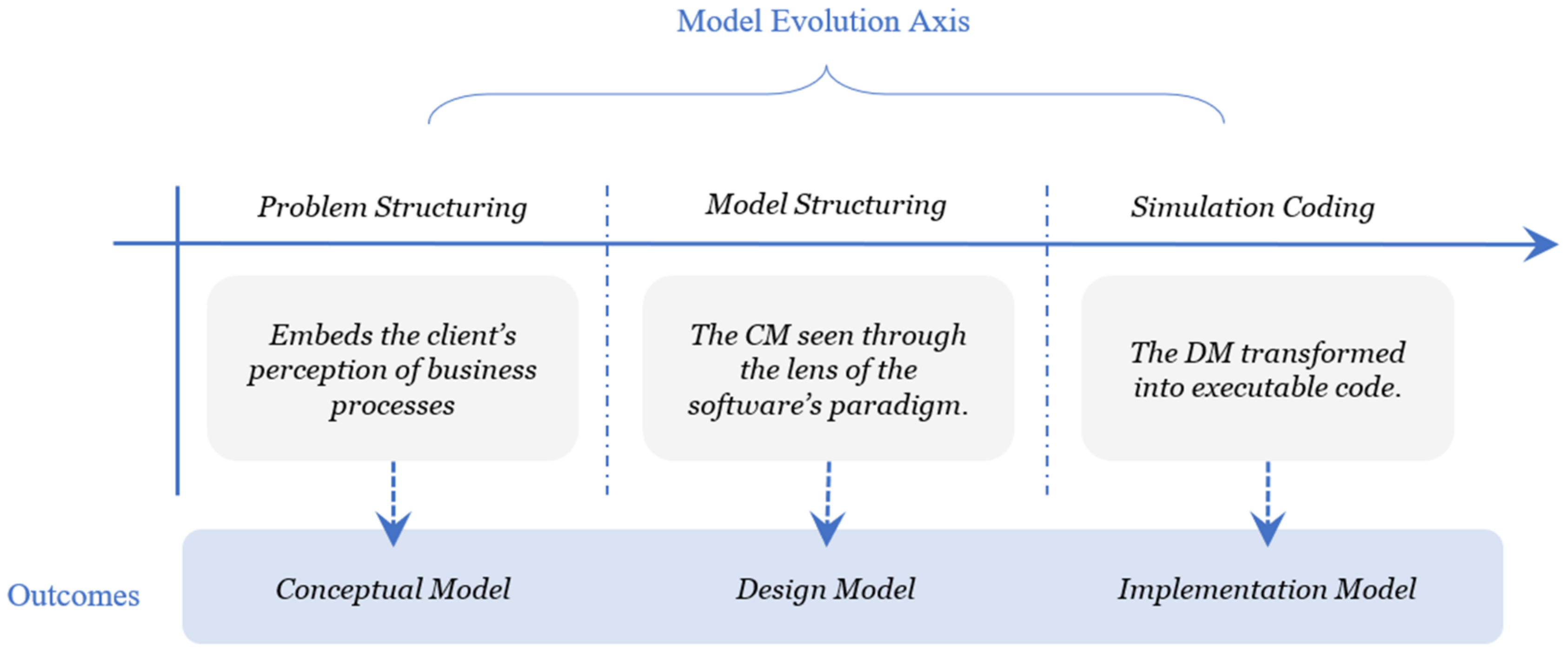
4.2. Model Transformation Process

4.2.1. Developing the Conceptual Model

The CM represents a shared and solution-independent representation of the system. Its purpose is being the first instance by which client and modeller share their understanding of the situation at hand. The problem-structuring process central to the development of the CM can be systematised with the modelling template, as seen in Figure 11. As the CM-S (first level conceptual model) is a black-box view of the system, we focus on identifying system-wide inputs/outputs. At the CM-T model is a high-level view of the business and requires laying out key processes. In contrast, the CM-O model is a detailed, albeit myopic, view of the internals of these processes.
The template provides a mechanism for ensuring congruence of the cognitive understanding of the various agents in the model-development process.

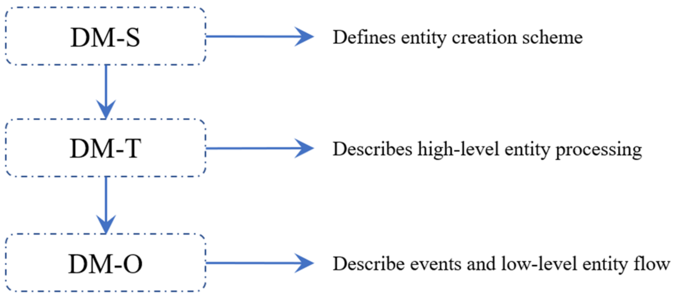
4.2.2. Developing the Design Model
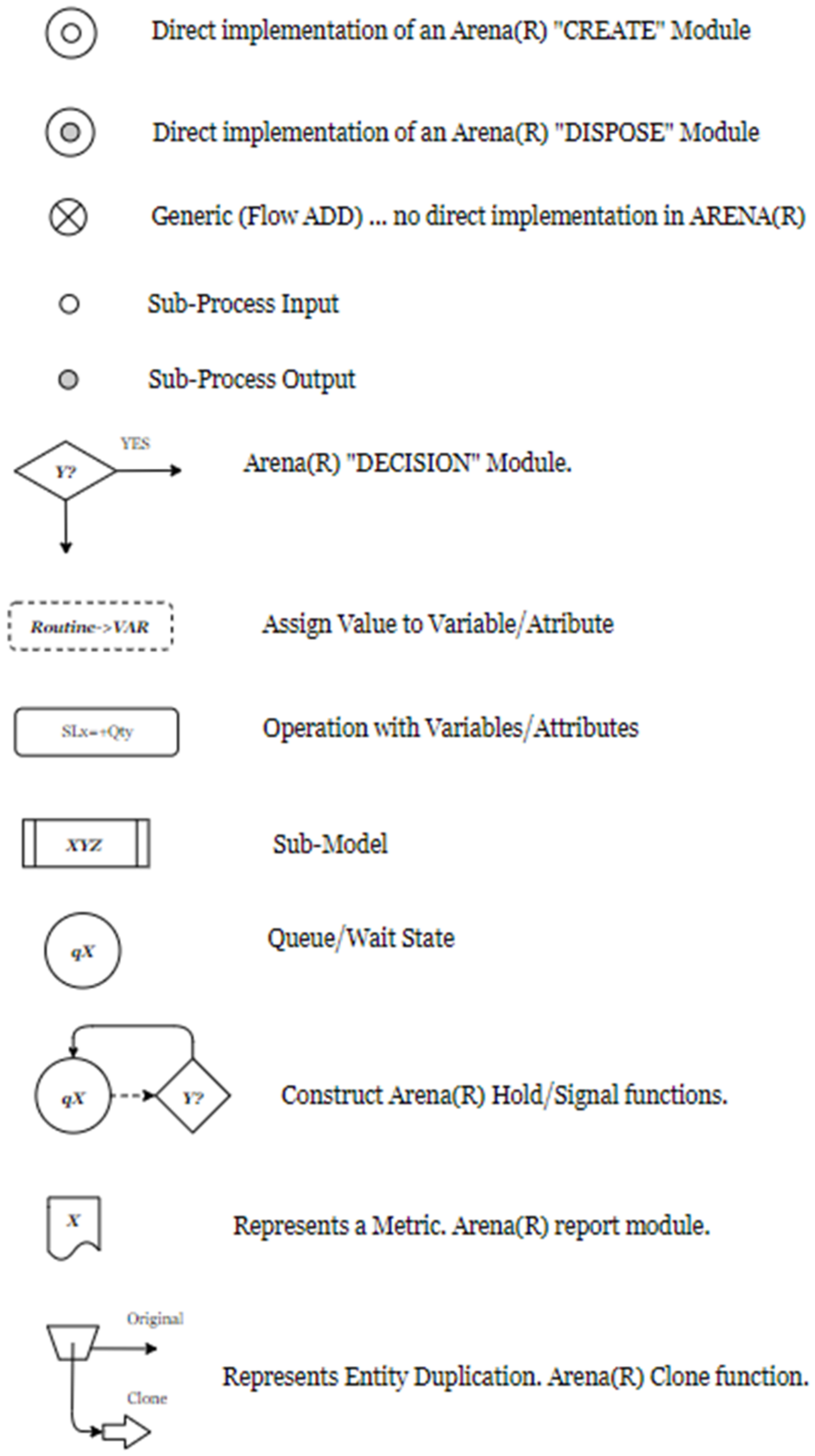
The role of the design model is to serve as a mid-step between the CM and the IM, allowing the problem situation as understood by operators to be re-formatted in terms of the simulation language worldview. This step is straightforward when using OO languages as they have greater flexibility in terms of mimicking abstract structures. In the case of non-OO languages, the transformation may not be as natural. Still, we believe in the combined use of the modelling template and specific considerations regarding the Process-Interaction approach (PI) allowed by the SIMAN language and the Arena® platform.
The process–interaction approach sees the world in terms of States (represented by state-variables) that change only upon the occurrence of predefined Events, caused by the flow of Entities and their corresponding interaction with certain parts of system [75,76]. Thus, Entities play a central role in PI modelling and will be the first step in the CM to DM transformation (Figure 12).
System state changes in the PI view can only be triggered by the arrival of entities [77]. As environmental interactions are a natural source of change in the real-life system, here we find our first source of the Entities. Thus, the first step in the development of the DM-S model involves the conversion of CM-S ‘interactions’ into an Entity type we called ‘Work-Orders (WO)’ (Figure 13).
As these entities flow through the system, other processes, which in PI languages result in alternative paths, triggered resulting in concurrent internal processes. As in PI only one process (namely that through which the active entity flows) can be active at a given time, we need to create a way of systematically ensuring this happens. Thus, we introduce the second rule, which states that if a process needs to interact with a peer, it should do so by cloning the WO, which gave way to the need, and feeding it back as a modified entity, now called a Request Order (RO). This second source of entities, related to the WO, but differentiated in time, act as inter-process messengers allowing key process to negotiate according to the LIP.
Thus, step two of the CM to DM conversion process is converting inter-process interaction into RO (Figure 13). A point worth noting is that certain system behaviours may not be representable through the process–interaction approach [45]. If this were to happen, the modeller will have to artificially cut this aspect out of the system and place it as part of the environment, where it can be modelled using other methods. Thus, in some cases, the modeller will need to iterate back to the CDM model to reflect this change. Our case study illustrates this situation as we had to model an internal agent-based decision process that is to be modelled as an external process (see Section 5.1 MRP as an environmental actor).
The last step is the transformation of the CM-O into a DM-O, which, although straightforward, has the added complication of the representation method. Having decided how to route incoming and fed-back entities, it is necessary to define the activities with which WO and RO will engage. For this, we re-write CM-O in a sequential form to obtain DM-O (Figure 13). This stage will mostly be carried out by the modeller as it requires a thorough understanding of the constructs upon which the software of choice is constructed. In our case, and due to the choice of Arena®, we developed a stripped-down version of its graphical language to represent the structure, without introducing nuanced details that would keep our clients from understanding the general flow of the program (see Figure 14).

Modelling Language

Regarding the modelling language to be used for the DM, we see no need to rely on standardised options. If the situation allows, the modeller may use universal types or develop an in-house option, the main point being that modeller and client need to be familiar with them. In our application our clients were not accustomed to using any of the common standard languages so we developed a stripped down version of the Arena® domain specific language [78] (Figure 14). Introducing a standard modelling languages as BPMN [79,80] or sysML [78,81] would have introduced and added an unnecessary cognitive, which we opted to avoid. In any case, as the specific languages used for the DM is not central to the framework, the user may choose freely.

4.2.3. Developing the Implementation Model

This final stage involves writing the software code, a process we called Model-Coding. Through this process we translate the DM pseudo-code to the simulation language of choice. The only requirements on the software side is for it to handle nested functions or subroutines, a functionality incorporated to Arena® in its later versions [1,75,82]. The actual coding process will be dependent on the language chosen as it will involve translating the DM as well as introducing ‘house-keeping’ code purposely ignored during the model-structuring process (Figure 15). This ancillary code typically involves error checking functions, data conversion, and accounting procedures to represent the performance metrics to be used in the model.

4.3. Integration

The overall approach is demonstrated in the case study of Section 5. There we show how we developed a CM with various layers in accordance with the Section 4.1 (Modelling Depth of Detail). Once completed we carry out the model transformation process of Section 4.2 (Model Transformation Process). The overall process (Figure 16) allows client and modeller on assumptions made at different levels of abstraction and during the software writing process improving model robustness by achieving higher conceptual model validation.

5. Applications to a Logistics Case Study

5.1. Conceptual Model

The Conceptual model was developed as a collaborative effort between the modeller and the logistics team. Starting with problem definition, the conceptual model was built through visits, interviews, and discussions with key referents. We found it easier to build the conceptual model starting from the operations plane as it was both more concrete and easier to explain. As we progressed through the operations plane, tactical level processes emerged naturally out of the description. The strategic level was the last to make itself clear, but later became the basis for later iterations.
The Conceptual model at the interaction plane level (CM-0) is an abstract agreement on what constitutes the system under study. In the case study, we developed an early-stage candidate which later changed due to the difficulty of including complex decision-making processes in the process-interaction worldview. The final version (Figure 17) includes a Distributed Inventory System (DIS) and two external blocks, MRP and SALES, which form the environment.
The Conceptual model at the systems plane level (CM-S) is a high-level overview of the system under study, highlighting the main processes. In the case study, the system is a group of deposit stores that interchange stock. The complexity of our system required us to break down the system plane layer into a two-level structure according the DHP and LIP principles. The top-level structure (CM-T) represented the network of stores, whilst sub-levels (CM-T-A and CM-T-B) represent processes occurring inside the deposit stores (Figure 18).
The Conceptual model at the operations plane level (CM-O) is the shop-floor representation of the business processes (Figure 19). This was our first interaction with the processes, so we found that representing the industry-specific operations with custom icons and using swim-lanes to group processes was an easy way to validate our understanding with the process-owners. Operations across the network are similar enough to allow one model for all stores. Moreover, as was later realised, Sales and MRP (procurement) had to be modelled outside of the Arena® environment.

5.2. Design Model

The DM at the strategic level (DM-S) was obtained by using the method outlined in Section 4.2.2, which stipulates using CM-S as a basis for the transformation process (Figure 20). In the final model, MRP and Sales were modelled outside the Arena® model and thus appear as environmental interactions in the model.
The DM at the tactical plane level (DM-T) was also developed via the method outlined in 4.2.2. As CM-T had sublevels (T-A and T-B), these gave way to DM-T-A and DM-T-B in the conversion process (Figure 21).
The DM at the operations plane level (DM-O) was also developed using the guidelines of Section 4.2.2. As the operations were numerous, multiple sublevels were needed to comply with the DHP and LIP principles (Figure 22).

5.3. Implementation Model

The implementation model was developed as per Section 4.2.3 from the DM, again inheriting a nested sub-model structure. At the interaction plane level (Figure 23), we still see a resemblance with both business processes and the conceptual model, which will fade away the deeper we go into the operations plane due to the ancillary code.
As we dive deeper into the details of the business operations the Implementation Model (Arena® graphical language) lose immediate resemblance. In the Implementation Model-Tactical Plane (IM-T), the inclusion of error checking code and other innate requirements of the programming language make it look slightly different and more complex (Figure 24).
As the CM-T and DM-T had two sub-models, these also translate into their IM versions (Figure 25).
In the Final stage, we represent the Implementation Model—Operations Plane. As these layers also had four processes represented as sub-models, they will also have their own representation (Figure 26). At this stage, the logic underlying logic becomes obscured by the code, which is the reason we opted to use an intermediate Design Model to discuss the logic and assumptions with our client.

5.4. Modelling Results

Upon completion, the IM was run using Arena version 16.1 with historical input and output (sales) data to determine inventory levels in two representative stores. The results are shown in Figure 27.
The precise interpretation of the results is not important here; rather, the diagram shows that the framework is successful in its ability to evolve detail in the model space. These results were presented to the client, who confirmed that it reflected their understanding of their inventory dynamics.

5.5. Evaluation of the Approach

It is difficult to evaluate the efficacy and efficiency of the approach on quantitative grounds. Subjective assessment indicates that the amount of effort required to develop the code was not necessarily reduced. Rather, the benefit was the increased face validity of the model. This was evident in confirmatory statements from the client, and their progressive acceptance of the model as it grew. The client appreciated the ability to adjust the direction of the model development, as they better understood the model and their own assumptions. The approach facilitated their ease of understanding and the development of the problem and solution spaces as the client understanding of the internal dynamics of their processes improved.

6. Discussion

6.1. Summary of Contributions

This work makes several novel contributions to the field of business process simulation. Firstly, it presents a systematic way of developing simulation models in a way that makes assumptions regarding system behaviour (client-side) and how this will be mirrored in software (modeller-side) explicit. The Model-Space template, which combines abstraction (Strategic-Tactical-Operation) and evolution (Conceptual-Design-Implementation) layers, serves as a bridge for both parts to express their implicit understanding. This is particularly important in the field of Discrete Event Simulation models of business processes as logistics. The fact that these processes are not solely governed by universal physical laws but by organisational policies, places a requirement on validation of any assumptions of applicability of ideas and pre-built software code that the modeller may have used in the past.
Second, not all modelling software used in industry is object-oriented; it allows a way of structuring the intermediate (design model) without using object-oriented constructs as objects and classes. Moreover, it facilitates embedment of a hierarchical breakdown structure with a process–interaction worldview supported by most of domain-specific modelling languages (even those with OO compatibility). It does so by relying on algorithmic (linear) decomposition made explicit by the layered model template. It also preserves the natural multiplicity of perspectives of process-owners by allowing them to co-exist the strategic–tactical–operational pyramid. Most important, it allows this layered perspective structure to be transferred into the final software by a conversion process that preserves the one-to-one correspondence between the way the situation is perceived in the Conceptual Model and the way the code is structured in the Implementation Model.
Thirdly, the whole process is conducted in a stepwise fashion, allowing client and modeller to engage in a continuous sharing of interpretation. This allows the transparency in regard to how the modeller will implement organisational dynamics in the software while minimising the technical jargon. This has the added benefit of helping the participants test their intuitive understanding of both the real system and the way it will be modelled in software. This both strengthens the validity of the model and contributes to the original aim of exploratory simulation endeavours as the improvement on the understanding of the systems characteristics and behaviour.

6.2. Implications for Practitioners

The framework stresses a division between problem-structuring and the code-structuring, placing a clearer aim for the modeller–client interaction at each stage. At the problem-structuring stage, the method should allow for multiple internal perspectives to be integrated. Assumptions regarding system behaviour and the way their dynamics will be represented in software becomes explicit in the different levels of abstractions or the model transformation process improving model robustness by achieving higher conceptual model validation.
The method allows tailoring to the amount of detail needed for each situation. The modularised nature of the development process allows owners of a specific aspect of the problem-situation to participate fully in whatever level they are required without having to understand the rest of the model behaviour, thus mirroring their real-world situation. Therefore, managers of high-level processes could participate in the development of the higher-level planes, while the modelling of lower-level activities could be performed with whoever oversees them.

6.3. Limitations of the Work

This work has several limitations. The first being the lengthiness of the process. In practice, this may limit its usefulness to situation in which either client participation is paramount or in which the complexity of the system requires careful validation of the model. Second is the focus on the process-interaction worldview. Again, this makes the framework useful primarily in cases where the implementation model will be parsed in a process-interaction based platform, as is the case of Arena®. Third is the assumption that the system to be modelled is structurally complex. By this, we mean complexity stemming from multiple interactions between simultaneous processes. In situations where complexity does not stem from a relatively large number of interacting elements, the cost of building the model through the stepwise process may not justify the insight obtained and thus may be disadvantageous. Finally, the DM lacks a versioning control method that could help keep track of changes as the development process progresses.

7. Conclusions

The purpose of this paper was to derive a framework to guide the development of exploration-aimed simulation models. In these endeavours, there is a need to ensure understanding between client and modeler so as to achieve greater model validity. This was achieved by integrating ideas from Systems and Software Engineering to build a layered abstraction scheme to serve as a template to a series of models, ending in the computer code. The integration is represented as a “modelling space”, which is populated by different types of models in an attempt to allow a natural flow from the mental model of the problem to an executable computer code. Guiding the process are the principles of function-as-seed (FAS), detailed-hierarchy (DHP), locality- and information-hiding, and localised interaction, which we combined under the localised-interaction-principle (LIP), which were combined with a hierarchy reminiscent of the Strategic–Tactical–Operational (STO) breakdown. The resulting template, called the modelling space, and snippets of a real-case application models are shown in Figure 28.
This paper demonstrates the feasibility of using a principles-based approach for developing simulation models. The proposed framework allows extended client participation in the model development process, which fosters the interchange of tacit knowledge resulting in better chances of reaching a valid model. The framework was demonstrated by its application to a case study in logistics. An extended benefit of the framework is its ability to frame the problem at hand in a way that does not rely on classes and objects and thus can be directly implemented in non-object-oriented software.

Author Contributions

Conceptualisation A.G. and D.P.; data curation A.G.; formal analysis A.G.; investigation A.G.; methodology A.G. and D.P.; software programming A.G.; supervision D.P.; validation A.G.; visualisation A.G.; writing—original draft: A.G.; writing—review & editing A.G. and D.P. All authors have read and agreed to the published version of the manuscript.

Funding

This research was supported by Callaghan Innovation R&D grant ARLAB2002.

Institutional Review Board Statement

Not applicable.

Informed Consent Statement

Not applicable.

Data Availability Statement

Not applicable.

Acknowledgments

We wish to thank the industry collaborator for support.

Conflicts of Interest

The authors declare no conflict of interest.

References

  1. Rossetti, M.D. Simulation Modelling and Arena, 2nd ed.; John Wiley & Sons, Inc.: Hoboken, NJ, USA, 2015; ISBN 978-1-118-60803-6. [Google Scholar]
  2. Robinson, S. General concepts of quality for discrete-event simulation. Eur. J. Oper. Res. 2002, 138, 103–117. [Google Scholar] [CrossRef]
  3. Robinson, S. A tutorial on simulation conceptual modelling. In Proceedings of the 2017 Winter Simulation Conference (WSC), Las Vegas, NV, USA, 3–6 December 2017; pp. 565–579. [Google Scholar]
  4. Sargent, R.; Nance, R.; Overstreet, C.; Robinson, S.; Talbot, J. The Simulation Project Life-Cycle: Models and Realities. In Proceedings of the 2006 Winter Simulation Conference, Monterey, CA, USA, 3–6 December 2006; pp. 863–871. [Google Scholar]
  5. Pidd, M. Tools for Thinking: Modelling in Management Science, 2nd ed.; Wiley: Chichester, UK; Hoboken, NJ, USA, 2003; ISBN 978-0-470-84795-4. [Google Scholar]
  6. Jackson, M.C. Beyond problem structuring methods: Reinventing the future of OR/MS. J. Oper. Res. Soc. 2006, 57, 868–878. [Google Scholar] [CrossRef]
  7. Pidd, M.; Robinson, S. Organising insights into simulation practice. In Proceedings of the 2007 Winter Simulation Conference, Washington, DC, USA, 9–12 December 2007; pp. 771–775. [Google Scholar]
  8. Van der Zee, D.-J. Developing participative simulation models—Framing decomposition principles for joint understanding. J. Simul. 2007, 1, 187–202. [Google Scholar] [CrossRef]
  9. Büschgens, T.; Bausch, A.; Balkin, D.B. Organizational Culture and Innovation: A Meta-Analytic Review: Organizational Culture and Innovation. J. Prod. Innov. Manag. 2013, 30, 763–781. [Google Scholar] [CrossRef]
  10. Ribeiro, S.C.M. Organizational Culture and Paradoxes in Management: Firms, Families, and Their Businesses, 1st ed.; Routledge: London, UK, 2020; ISBN 978-0-429-26574-7. [Google Scholar]
  11. Van Nistelrooij, L.P.J.; Rouwette, E.A.J.A.; Verstijnen, I.M.; Vennix, J.A.M. The Eye of the Beholder: A Case Example of Changing Clients’ Perspectives Through Involvement in the Model Validation Process: The Eye of the Beholder. Syst. Res. Behav. Sci. 2015, 32, 437–449. [Google Scholar] [CrossRef]
  12. Muller-Merbach, H. Five notions of OR/MS problems. Omega 2011, 39, 1–2. [Google Scholar] [CrossRef]
  13. Robinson, S.; Arbez, G.; Birta, L.G.; Tolk, A.; Wagner, G. Conceptual modelling: Definition, purpose and benefits. In Proceedings of the 2015 Winter Simulation Conference (WSC), Huntington Beach, CA, USA, 6–9 December 2015; pp. 2812–2826. [Google Scholar]
  14. Tolk, A.; Turnitsa, C. Conceptual modelling with processes. In Proceedings of the 2012 Winter Simulation Conference (WSC), Berlin, Germany, 9–12 December 2012; pp. 1–13. [Google Scholar]
  15. Booch, G.; Maksimchuk, R.A.; Engle, M.W.; Young, B.J.; Connallen, J.; Houston, K.A. Object-oriented analysis and design with applications, third edition. ACM SIGSOFT Softw. Eng. Notes 2008, 33, 29. [Google Scholar] [CrossRef]
  16. Sargent, R.G. Verification And Validation Of Simulation Models: An Advanced Tutorial. In Proceedings of the 2020 Winter Simulation Conference (WSC), Orlando, FL, USA, 14–18 December 2020; pp. 16–29. [Google Scholar]
  17. Sargent, R.G. Verification and validation of simulation models. In Proceedings of the 2010 Winter Simulation Conference, Baltimore, MD, USA, 5–8 December 2010; pp. 166–183. [Google Scholar]
  18. Van der Zee, D.-J.; Van der Vorst, J.G.A.J. Guiding principles for conceptual model creation in manufacturing simulation. In Proceedings of the 2007 Winter Simulation Conference, Washington, DC, USA, 9–12 December 2007; pp. 776–784. [Google Scholar]
  19. Evans, E. Domain-Driven Design: Tackling Complexity in the Heart of Software; Addison-Wesley: Boston, MA, USA, 2004; ISBN 978-0-321-12521-7. [Google Scholar]
  20. Walden, D.D.; Roedler, G.J.; Forsberg, K.; Hamelin, R.D.; Shortell, T.M. (Eds.) International Council on Systems Engineering. In Systems Engineering Handbook: A Guide for System Life Cycle Processes and Activities, 4th ed.; Wiley: Hoboken, NJ, USA, 2015; ISBN 978-1-118-99941-7. [Google Scholar]
  21. Wagner, G.; Seck, M.; McKenzie, F. Process modelling for simulation: Observations and open issues. In Proceedings of the 2016 Winter Simulation Conference (WSC), Washington, DC, USA, 11–14 December 2016; pp. 1072–1083. [Google Scholar]
  22. Doumeingts, G.; Vallespir, B.; Chen, D. GRAI Grid Decisional Modelling. In Handbook on Architectures of Information Systems; Bernus, P., Mertins, K., Schmidt, G., Eds.; Springer: Berlin/Heidelberg, Germany, 1998; pp. 313–337. ISBN 978-3-662-03528-3. [Google Scholar]
  23. Zacharewicz, G.; Pirayesh-Neghab, A.; Seregni, M.; Ducq, Y.; Doumeingts, G. Simulation-Based Enterprise Management. In Guide to Simulation-Based Disciplines; Mittal, S., Durak, U., Ören, T., Eds.; Simulation Foundations, Methods and Applications; Springer International Publishing: Cham, Switzerland, 2017; pp. 261–289. ISBN 978-3-319-61263-8. [Google Scholar]
  24. Zacharewicz, G.; Daclin, N.; Doumeingts, G.; Haidar, H. Model Driven Interoperability for System Engineering. Modelling 2020, 1, 94–121. [Google Scholar] [CrossRef]
  25. Haberfellner, R.; de Weck, O.; Fricke, E.; Vössner, S. Systems Engineering: Fundamentals and Applications; Springer International Publishing: Cham, Switzerland, 2019; ISBN 978-3-030-13430-3. [Google Scholar]
  26. Šerifi, V.; Daši, P. Functional and Information Modeling of Production Using IDEF Methods. J. Mech. Eng. 2009, 55, 131–140. [Google Scholar]
  27. Ma, L.; Xia, F.; Peng, Z. Integrated Design and Implementation of Embedded Control Systems with Scilab. Sensors 2008, 8, 5501–5515. [Google Scholar] [CrossRef] [Green Version]
  28. Sztipanovits, J.; Karsai, G.; Biegl, C.; Bapty, T.; Ledeczi, A.; Misra, A. MULTIGRAPH: An architecture for model-integrated computing. In Proceedings of the First IEEE International Conference on Engineering of Complex Computer Systems, ICECCS’95, Fort Lauderdale, FL, USA, 6–10 November 1995; pp. 361–368. [Google Scholar]
  29. Kogler, C.; Rauch, P. Discrete event simulation of multimodal and unimodal transportation in the wood supply chain: A literature review. Silva Fenn. 2018, 52, 29. [Google Scholar] [CrossRef]
  30. Robinson, S. Conceptual modelling for simulation Part I: Definition and requirements. J. Oper. Res. Soc. 2008, 59, 278–290. [Google Scholar] [CrossRef] [Green Version]
  31. Sargent, R.G. Verification and validation of simulation models. J. Simul. 2013, 7, 12–24. [Google Scholar] [CrossRef] [Green Version]
  32. Bock, C.; Dandashi, F.; Friedenthal, S.; Harrison, N.; Jenkins, S.; McGinnis, L.; Sztipanovits, J.; Uhrmacher, A.; Weisel, E.; Zhang, L. Conceptual Modelling. In Research Challenges in Modelling and Simulation for Engineering Complex Systems; Fujimoto, R., Bock, C., Chen, W., Page, E., Panchal, J.H., Eds.; Simulation Foundations, Methods and Applications; Springer International Publishing: Cham, Switzerland, 2017; pp. 23–44. ISBN 978-3-319-58543-7. [Google Scholar]
  33. Balci, O.; Ormsby, W.F. Well-defined intended uses: An explicit requirement for accreditation of modelling and simulation applications. In Proceedings of the 2000 Winter Simulation Conference Proceedings (Cat. No.00CH37165), Orlando, FL, USA, 10–13 December 2000; Volume 1, pp. 849–854. [Google Scholar]
  34. Sargent, R.G.; Balci, O. History of verification and validation of simulation models. In Proceedings of the 2017 Winter Simulation Conference (WSC), Las Vegas, NV, USA, 3–6 December 2017; pp. 292–307. [Google Scholar]
  35. Larsen, M.E.V.; Deantoni, J.; Mallet, F. Framework for Heterogeneous Modeling and Composition; HAL: Paris, France, 2014; pp. 81–85. Available online: https://hal.archives-ouvertes.fr/hal-01073202 (accessed on 2 May 2022).
  36. Karsai, G.; Narayanan, A. On the Correctness of Model Transformations in the Development of Embedded Systems. In Composition of Embedded Systems. Scientific and Industrial Issues; Kordon, F., Sokolsky, O., Eds.; Lecture Notes in Computer Science; Springer: Berlin/Heidelberg, Germany, 2008; Volume 4888, pp. 1–18. ISBN 978-3-540-77418-1. [Google Scholar]
  37. Müller-Merbach, H. Our secret code. Omega 2010, 38, 1–2. [Google Scholar] [CrossRef]
  38. Zhou, M.; Son, Y.J.; Chen, Z. Knowledge Representation for Conceptual Simulation Modelling. In Proceedings of the 2004 Winter Simulation Conference, Washington, DC, USA, 5–8 December 2004; Volume 1, pp. 440–448. [Google Scholar]
  39. McGinnis, L.; Huang, E.; Kwon, K.S.; Ustun, V. Ontologies and simulation: A practical approach. J. Simul. 2011, 5, 190–201. [Google Scholar] [CrossRef]
  40. Balci, O. Golden Rules of Verification, Validation, Testing, and Certification of Modelling and Simulation Applications. SCS MS Mag. 2010, 4, 7. [Google Scholar]
  41. Robinson, S. Tutorial: Choosing what to model-Conceptual modelling for simulation. In Proceedings of the 2012 Winter Simulation Conference (WSC), Berlin, Germany, 9–12 December 2012; pp. 1–12. [Google Scholar]
  42. Robinson, S.; Brooks, R.; Kotiadis, K.; van der Zee, D.-J. Conceptual Modelling for Discrete-Event Simulation; CRC Press: Boca Raton, FL, USA, 2011; ISBN 978-1-4398-1038-5. [Google Scholar]
  43. Robinson, S. Simulation: The Practice of Model Development and Use, 2nd ed.; Palgrave Macmillan: Basingstoke, UK; New York, NY, USA, 2014; ISBN 978-1-137-32802-1. [Google Scholar]
  44. Atkinson, C.; Kühne, T. Reducing accidental complexity in domain models. Softw. Syst. Model. 2008, 7, 345–359. [Google Scholar] [CrossRef]
  45. Roberts, S.D.; Pegden, D. The history of simulation modelling. In Proceedings of the 2017 Winter Simulation Conference (WSC), Las Vegas, NV, USA, 3–6 December 2017; pp. 308–323. [Google Scholar]
  46. Banks, J. Discrete-Event System Simulation, 5th ed.; New Internat. Ed.; Pearson: Harlow, UK, 2014; ISBN 978-1-292-02437-0. [Google Scholar]
  47. Pegden, C.D. Advanced tutorial: Overview of simulation world views. In Proceedings of the 2010 Winter Simulation Conference, Baltimore, MD, USA, 5–8 December 2010; pp. 210–215. [Google Scholar]
  48. Davis, D.A.; Pegden, C.D. Introduction to SIMAN. In Proceedings of the 20th Conference on Winter Simulation—WSC ‘88, San Diego, CA, USA, 12–14 December 1988; pp. 61–70. [Google Scholar]
  49. van der Zee, D.J.; van der Vorst, J.G.A.J. A Modelling Framework for Supply Chain Simulation: Opportunities for Improved Decision Making. Decis. Sci. 2005, 36, 65–95. [Google Scholar] [CrossRef]
  50. Dias, L.M.S.; Vieira, A.A.C.; Pereira, G.A.B.; Oliveira, J.A. Discrete simulation software ranking—A top list of the worldwide most popular and used tools. In Proceedings of the 2016 Winter Simulation Conference (WSC), Washington, DC, USA, 11–14 December 2016; pp. 1060–1071. [Google Scholar]
  51. Šebalj, D. Simulation model of natural gas supply chain in a function of costs optimization: The case of Croatia. SN Appl. Sci. 2022, 4, 18. [Google Scholar] [CrossRef]
  52. Moody, D. Cognitive Load Effects on End User Understanding of Conceptual Models: An Experimental Analysis. In Advances in Databases and Information Systems; Benczúr, A., Demetrovics, J., Gottlob, G., Eds.; Lecture Notes in Computer Science; Springer: Berlin/Heidelberg, Germany, 2004; Volume 3255, pp. 129–143. ISBN 978-3-540-23243-8. [Google Scholar]
  53. Muntean, A.; Inţă, M.; Stroilă, I.A. A Study on Improving Logistics in a Production Enterprise in the Automotive Domain. IOP Conf. Ser. Mater. Sci. Eng. 2016, 161, 012101. [Google Scholar] [CrossRef] [Green Version]
  54. Iannone, R.; Miranda, S.; Prisco, L.; Riemma, S.; Sarno, D. Proposal for a flexible discrete event simulation model for assessing the daily operation decisions in a Ro–Ro terminal. Simul. Model. Pract. Theory 2016, 61, 28–46. [Google Scholar] [CrossRef]
  55. Miranzadeh, A.; Sajadi, S.M.; Tavakoli, M.M. Simulation of a single product supply chain model with ARENA. Int. J. Ind. Syst. Eng. 2015, 19, 18. [Google Scholar] [CrossRef]
  56. Campos, T.M.C.; Carvalho, M.S.; Oliveira, J.A.V.; Vaz, S.P. Using Discrete Simulation to Support Internal Logistics Process Design; Curran Associates, Inc.: Red Hook, NY, USA, 2017; p. 9. [Google Scholar]
  57. Ravichandran, M.; Naresh, R.; Kandasamy, J. Supply Chain Routing in a Diary Industry Using Heterogeneous Fleet System: Simulation-Based Approach. J. Inst. Eng. India Ser. C 2020, 101, 891–911. [Google Scholar] [CrossRef]
  58. Jayant, A.; Gupta, P.; Garg, S.K. Simulation Modelling and Analysis of Network Design for Closed-Loop Supply Chain: A Case Study of Battery Industry. Procedia Eng. 2014, 97, 2213–2221. [Google Scholar] [CrossRef] [Green Version]
  59. Gunal, M.M.; Pidd, M. Understanding target-driven action in emergency department performance using simulation. Emerg. Med. J. 2009, 26, 724–727. [Google Scholar] [CrossRef]
  60. Günal, M.M.; Pidd, M. DGHPSIM: Generic simulation of hospital performance. ACM Trans. Model. Comput. Simul. 2011, 21, 1–22. [Google Scholar] [CrossRef]
  61. Object Management Group. “MDA Guide Rev. 2.0.” Object Management Group (OMG). Available online: https://www.omg.org/cgi-bin/doc?ormsc/14-06-01 (accessed on 18 June 2014).
  62. Bocciarelli, P.; D’Ambrogio, A.; Falcone, A.; Garro, A.; Giglio, A. A Model-Driven Approach to Enable the Distributed Simulation of Complex Systems. In Complex Systems Design & Management. Proceedings of the Sixth International Conference on Complex Systems Design & Management, CSD&M, Paris, France, 23–25 November 2015; Auvray, G., Bocquet, J.-C., Bonjour, E., Krob, D., Eds.; Springer International Publishing: Cham, Switzerland, 2016; ISBN 978-3-319-26107-2. [Google Scholar]
  63. Tolk, A. Ontology Driven Interoperability–M&S Applications. Whitepaper Support I/ITSEC Tutor. 2006, 15, 2548. [Google Scholar]
  64. Zacharewicz, G.; Diallo, S.; Ducq, Y.; Agostinho, C.; Jardim-Goncalves, R.; Bazoun, H.; Wang, Z.; Doumeingts, G. Model-based approaches for interoperability of next generation enterprise information systems: State of the art and future challenges. Inf. Syst. e-Bus. Manag. 2017, 15, 229–256. [Google Scholar] [CrossRef] [Green Version]
  65. Bazoun, H.; Zacharewicz, G.; Ducq, Y.; Boyé, H. SLMToolBox: An Implementation of MDSEA for Servitisation and Enterprise Interoperability. In Enterprise Interoperability VI.; Mertins, K., Bénaben, F., Poler, R., Bourrières, J.-P., Eds.; Springer International Publishing: Cham, Switzerland, 2014; pp. 101–111. ISBN 978-3-319-04947-2. [Google Scholar]
  66. Carr, J.T.; Balci, O. Verification and validation of object-oriented artifacts throughout the simulation model development life cycle. In Proceedings of the 2000 Winter Simulation Conference (Cat. No.00CH37165), Orlando, FL, USA, 10–13 December 2000; Volume 1, pp. 866–871. [Google Scholar]
  67. Nydick, R.L.; Liberatore, M.J.; Chung, Q.B. Modelling By Elaboration: An Application To Visual Process Simulation. INFOR Inf. Syst. Oper. Res. 2002, 40, 347–361. [Google Scholar] [CrossRef]
  68. Guru, A.; Savory, P. A Template-Based Conceptual Modelling Infrastructure for Simulation of Physical Security Systems. In Proceedings of the 2004 Winter Simulation Conference, Washington, DC, USA, 5–8 December 2004; Volume 1, pp. 849–856. [Google Scholar]
  69. Simon, H.A. The Sciences of the Artificial, 3rd ed.; Nachdr.; MIT Press: Cambridge, MA, USA, 2008; ISBN 978-0-262-19374-0. [Google Scholar]
  70. Dori, D. Model-Based Systems Engineering with OPM and SysML.; Springer: New York, NY, USA, 2016; ISBN 978-1-4939-3294-8. [Google Scholar]
  71. Ousterhout, J.K. A Philosophy of Software Design; Yaknyam Press: Palo Alto, CA, USA, 2018; ISBN 978-1-73210-220-0. [Google Scholar]
  72. Cota, B.A.; Sargent, R.G. A modification of the process interaction world view. ACM Trans. Model. Comput. Simul. 1992, 2, 109–129. [Google Scholar] [CrossRef]
  73. Parnas, D.; Clements, P.; Weiss, D. The Modular Structure of Complex Systems. IEEE Trans. Softw. Eng. 1985, SE-11, 259–266. [Google Scholar] [CrossRef]
  74. Damelio, R. The Basics of Process Mapping, 2nd ed.; CRC Press: Boca Raton, FL, USA; Taylor & Francis Group: Milton, UK, 2016; ISBN 978-1-4398-9127-8. [Google Scholar]
  75. Kelton, W.D.; Sadowski, R.P.; Zupick, N.B. Simulation with Arena, 6th ed.; McGraw-Hill Education: New York, NY, USA, 2015; ISBN 978-0-07-340131-7. [Google Scholar]
  76. Law, A.M. Simulation Modelling and Analysis, 5th ed.; McGraw-Hill series in industrial engineering and management science; McGraw-Hill Education: Dubuque, IA, USA, 2013; ISBN 978-0-07-340132-4. [Google Scholar]
  77. Preston White, K.; Ingalls, R.G. The basics of simulation. In Proceedings of the 2017 Winter Simulation Conference (WSC), Las Vegas, NV, USA, 3–6 December 2017; pp. 505–519. [Google Scholar]
  78. Batarseh, O.; McGinnis, L.F. System modelling in SYsML and system analysis in Arena. In Proceedings of the 2012 Winter Simulation Conference (WSC), Berlin, Germany, 9–12 December 2012; pp. 1–12. [Google Scholar]
  79. OMG. Business Process Model and Notation (BPMN); Version 2.0; Springer: Berlin/Heidelberg, Germany, 2010; p. 532. [Google Scholar]
  80. Bocciarelli, P.; D’Ambrogio, A.; Giglio, A.; Paglia, E. BPMN-Based Business Process Modelling and Simulation. In Proceedings of the 2019 Winter Simulation Conference (WSC), National Harbor, MD, USA, 8–11 December 2019; pp. 1439–1453. [Google Scholar]
  81. Bakar, N.W.A.; Musa, S.; Mohamad, A.H. A Mini Comparative Study of Requirements Modelling Diagrams towards Swimlane: Evidence of Enterprise Resource Planning System. J. Phys. Conf. Ser. 2020, 1529, 052054. [Google Scholar] [CrossRef]
  82. Altiok, T.; Melamed, B. Simulation Modelling and Analysis with Arena; Academic Press: Amsterdam, The Netherlands; Boston, MA, USA, 2007; ISBN 978-0-12-370523-5. [Google Scholar]
Figure 1. First-order Control Loop.
Modelling 03 00018 g001
Figure 2. Stages of the simulation model development.
Modelling 03 00018 g002
Figure 3. Modelling Space as the set of choices to be made during the development of the model.
Modelling 03 00018 g003
Figure 4. Model transformation: from conceptual to Simulation, subject to the allowances of the software paradigm.
Modelling 03 00018 g004
Figure 5. Modelling Abstraction levels. Each levels representing a trade-off between scope and span.
Modelling 03 00018 g005
Figure 6. Naming of models according to their position in the modelling space.
Modelling 03 00018 g006
Figure 7. Layered template for Modelling Abstraction levels.
Modelling 03 00018 g007
Figure 8. The Strategic Plane focuses on system-wide interactions.
Modelling 03 00018 g008
Figure 9. The Tactical plane focuses on main process interactions.
Modelling 03 00018 g009
Figure 10. The Operations Plane focuses on transformational activities.
Modelling 03 00018 g010
Figure 11. Conceptual Model in the Layered Template Form.
Modelling 03 00018 g011
Figure 12. Design Model in the Layered Template Form.
Modelling 03 00018 g012
Figure 13. Converting the Conceptual Model to a Design Model.
Modelling 03 00018 g013
Figure 14. Pseudo-code in place of the Arena® graphical language.
Modelling 03 00018 g014
Figure 15. Converting the Design Model to an Implementation Model.
Modelling 03 00018 g015
Figure 16. Steps in the of the development process.
Modelling 03 00018 g016
Figure 17. Conceptual Model—Interaction Plane (CM-S). * Inter-store transfers not applicable to all stores.
Modelling 03 00018 g017
Figure 18. Conceptual Model—Tactical plane CM-T (blue) and sub-planes CM-T-A & CM-T-B (green). The round inset is meant to show that CM-T contains both CM-T-A and CM-T-B.
Modelling 03 00018 g018
Figure 19. Conceptual Model—Operations Plane (CM-O) represented in swim lane form. We developed the CM-O with our own symbols. Optionally BPMN notation could have been used.
Modelling 03 00018 g019
Figure 20. Conversion from CM-S (detailed in Figure 18) to Design Model–Strategic level (DM-S). System elements highlighted in blue, environmental actors in pink.
Modelling 03 00018 g020
Figure 21. Conversion of CM-T (detailed in Figure 18) to Design Model—Tactical planes. Main plane (DM-T) highlighted in blue and sub-plane DM-T-A in green.
Modelling 03 00018 g021
Figure 22. Conversion of CM-T-A to DM-T-A (detailed in Figure 18 and Figure 21) and finally into one of the Design Model—Operations sub-planes (DM-O-A.2) highlighted in beige.
Modelling 03 00018 g022
Figure 23. Conversion of CM-S to DM-S (detailed in Figure 17 and Figure 20) and finally into IM-S. System elements are highlighted in blue and environmental actors in pink.
Modelling 03 00018 g023
Figure 24. Conversion of DM-T into IM-T highlighted in beige. Top left is DM-S (detailed in Figure 20), from where top right DM-T comes from (detailed in Figure 21). The diagram shows the relationship between the sub-models. The details of the individual models are not relevant to the present discussion.
Modelling 03 00018 g024
Figure 25. Conversion of DM-T-A into IM-T-A sub-model highlighted in beige. Top left is DM-T and top right sub-model DM-T-A (both detailed in Figure 21). The diagram shows the relationship between the sub-models. The details of the individual models are not relevant to the present discussion.
Modelling 03 00018 g025
Figure 26. Conversion of DM-0-A.2 into IM-0-A.2 highlighted in beige. Top left is DM-T-A (detailed in Figure 21) and top right is DM-O-A.2 (detailed in Figure 22). The diagram shows the relationship between the sub-models. The details of the individual models are not relevant to the present discussion.
Modelling 03 00018 g026
Figure 27. Snippet from the Arena® dashboard with some of the modelling results.
Modelling 03 00018 g027
Figure 28. Modelling Space populated with representative models from the case study.
Modelling 03 00018 g028
Publisher’s Note: MDPI stays neutral with regard to jurisdictional claims in published maps and institutional affiliations.

