
Data Integration and Interoperability: Towards a Model-Driven and Pattern-Oriented Approach

Abstract
:1. Introduction and Methodology
1.1. Introduction to Data Integration
1.2. Methodology for a Model-Driven and Pattern-Oriented Data Integration: Overview
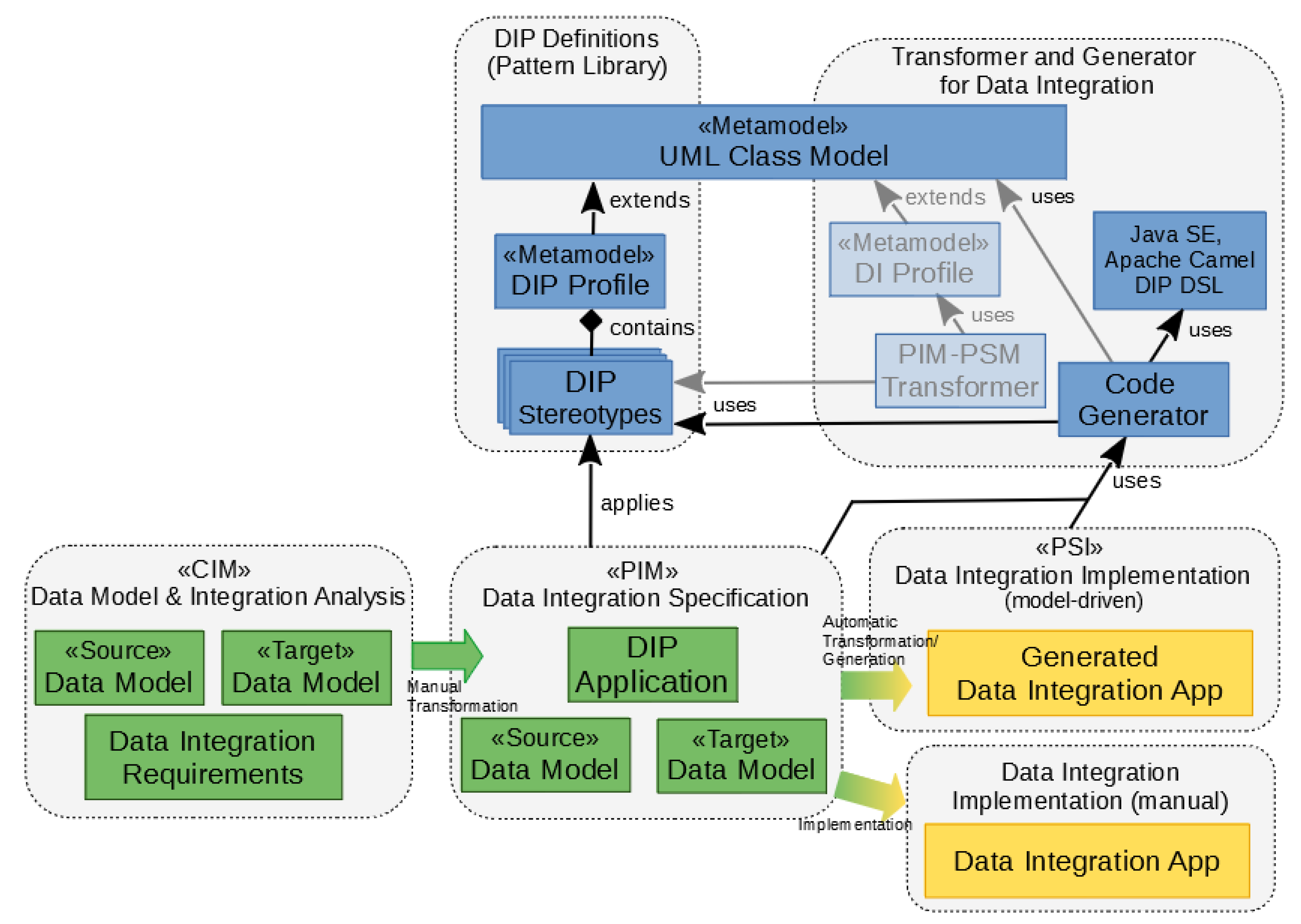
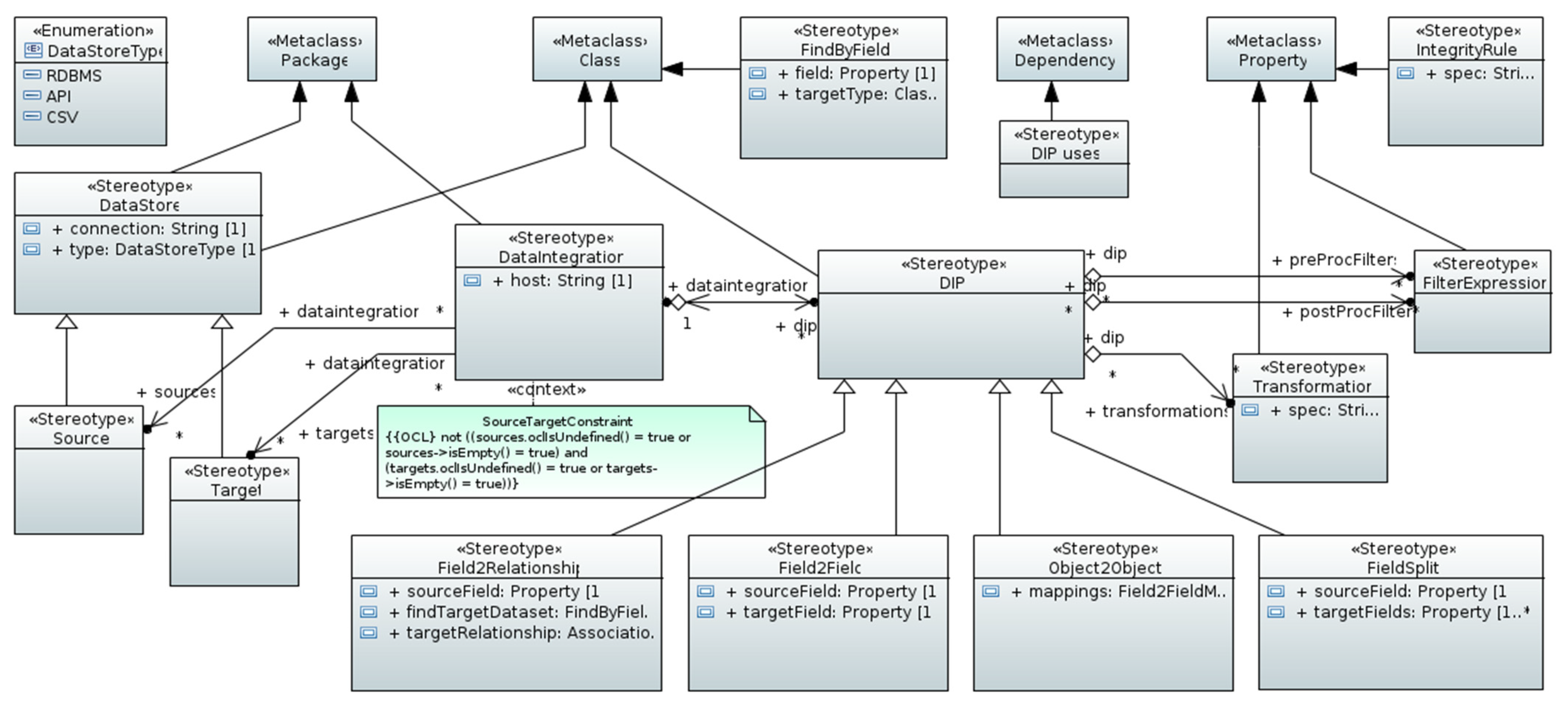
- DIP definitions: Formal definitions of DIPs are an integral and essential part of the approach. The outcome is a DIP catalog (or library) that is provided to the system analyst or data expert. As mentioned before, UML class diagrams are used for the DIP definitions using a UML DIP profile that extends the meta-classes “Class” and defines stereotypes with properties (tagged values). This lightweight approach for metamodeling is useful in cases such as DIPs where existing UML meta elements can be reused and extended, avoiding the introduction of new metamodel elements on M2 (metamodel level). DIPs are used in the context of PIMs (platform independent model) [6] (p. 11);
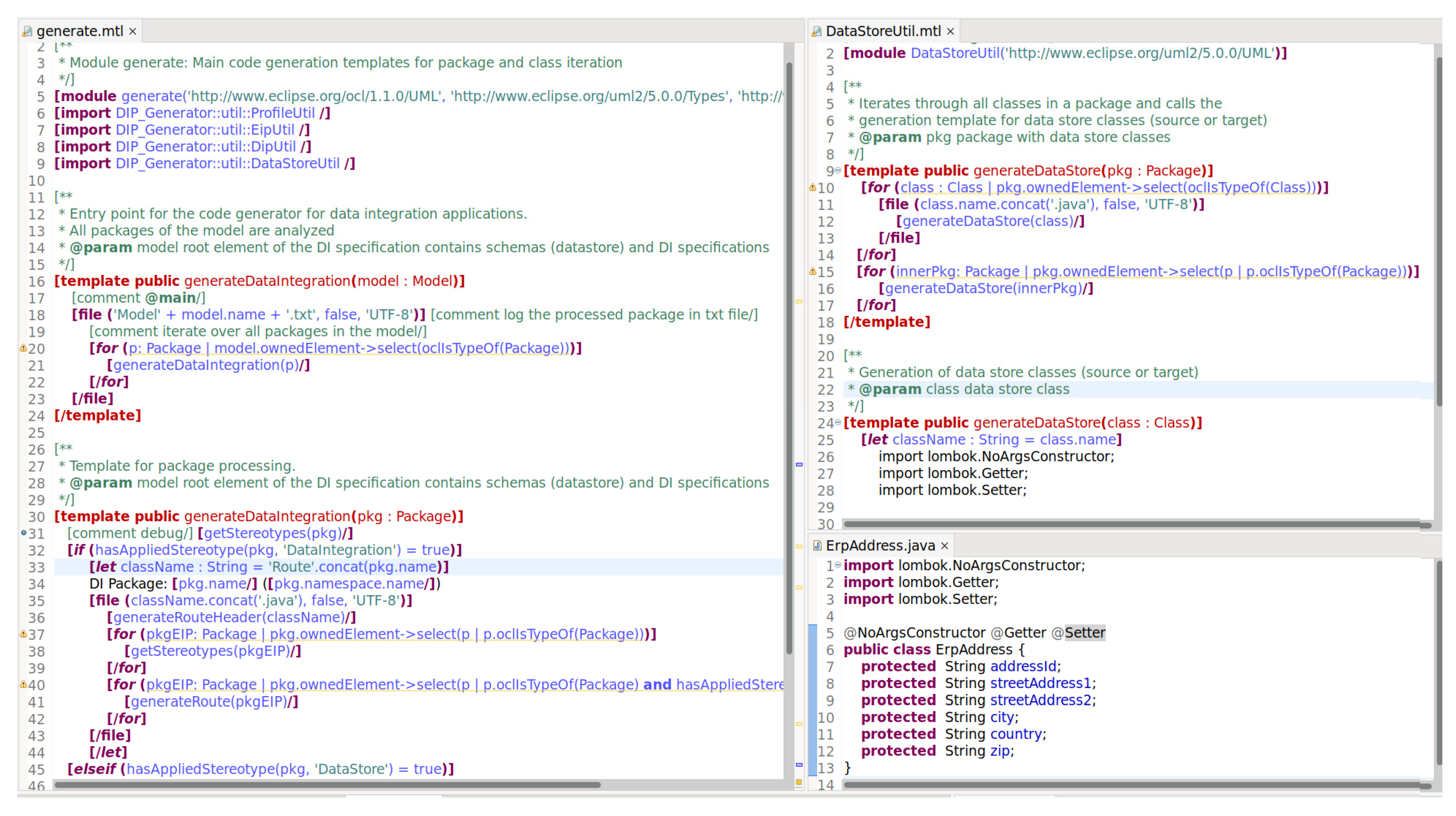
- Code generation for data integrations: This part represents the development of a transformer and code generator that can be used in data integration projects. The transformation of a PIM requires a DI profile that leads to a PSM (platform specific model) [6] (p. 11). The transformer is omitted here in order to simplify the methodology and keep the example as compact as possible. Therefore, a code generator was developed that creates code as a PSI (platform specific implementation (PSI is an officially introduced concept in the MDA Guide but since the “PIM/PSM pattern relates these different levels of abstraction and the concepts of PIM and PSM are, therefore, relative” [6] (p. 11), the last PIM–PSM transformation with text and code as its output artefacts leads to the term PSI (instead of PSM) [9] (p. 456), see also [10] (p. 3).)) directly from PIMs. This direct PIM–PSI approach lacks the flexibility that comes with PIM–PSM transformations but is considered sufficient for a PoC (proof of concept). The code generator for M2T (model-to-text transformation) uses a template engine (Eclipse Obeo Acceleo, [11]) that complies with OMG’s Mof2Text (MOF to text template language, [10]).
- Data model and integration analysis: during this mainly manual step that produces a CIM (computation independent model) [6] (p. 8), source and target data models and elements are analyzed and requirements of data integration are defined and documented;
- Data integration specification: During the DI specification, DIPs are applied to the source and target data elements leading to DI-specific UML class diagrams that act as a PIM (M1, model level). The application of stereotypes to UML model elements on M1 is often called “model marking” (or “to mark up a model” [12]). Class models marked with DIPs can then be used for further transformations or code generations because of their formal characteristic. The applied DIPs map source and target data elements, define conversions, aggregations, and other transformation logic;
- Data integration implementation: In order to be able to generate an executable data integration application that connects two or more systems providing source and target data, the DI specification that represents the PIM (or PSM) needs to be provided. The generator performs a model-to-text transformation (in terms of OMG’s MDA) where the text is the code and other artifacts represent the PSI on M1 (model level). As an alternative, the implementation can be performed manually without a code generator. Again, the output is an executable application for (reoccurring) data integration tasks. In both scenarios, a Java DSL (domain specific language) for DIPs developed to support DI implementation projects is used for generation or programming [13].
2. Related Work
3. Data Integration and Data Integration Patterns
3.1. Data Models for Enterprise Software Systems
- A data warehouse (DW) contains all the data from heterogeneous data sources (enterprise applications). A DW can store data in a dimensional or normalized manner, centralized or decentralized, and in different formats, but in either way, it provides an integrated view on data, often through OLAP, e.g., drill-down, dicing, slicing, roll-up, or pivoting. Data warehousing is a uni-directional approach: data is extracted from operational systems to the DW, but not vice versa;
- A system that follows a micro-service architectural approach and implements the “Database per service” patterns [27] to store data in a decentralized way. The integrated view can be archived with the “Command Query Responsibility Segregation (CQRS)” pattern on the database level and the “API Composition” pattern with in-memory data merging.
3.2. Data Integration: Introduction and Definition
3.3. Data Integration Patterns
3.4. Enterprise Integration Patterns
4. Model-Driven and Pattern-Oriented Method for Data Integration Tasks
4.1. Methodology Task Definition
- Verification of prerequisites: ensure that the necessary information about the systems and services, including the data models and business processes, is available, up-to-date, and correct;
- Identification of data integration tasks: based on the (business) processes and the source and target systems and services, tasks for data integration are identified. This activity leads to a list of potential data integration relevant tasks that also include the process-oriented context;
- Analyze, break down, and specify data integration tasks in connection with communication and messaging: some DI tasks are simple, but others are complex and consist of communication routing or logic, conversion, translation, or similar. The tasks should be analyzed and described. Complex tasks should be broken down into smaller tasks. Not only is the data integration important in the narrow sense, but also its context is important during this step, e.g., the communication mechanisms between systems or services;
- Application of EIPs and DIPs: this is probably one of the most important steps but can also be challenging because it requires knowledge about the domain, the processes, the data, and the patterns. After the messaging is clarified (application of EIPs), the data-oriented aspects can be addressed, and DIPs are applied. Sometimes the data aspect is so dominant that EIPs and DIPs must be used as a “package”, i.e., they build one inseparable compound pattern;
- Implement or generate integration: during implementation (or generation of the code), the system and data integration should be simulated or tested based on the specified tests. Code coverage is insufficient because of the relevance of the data. Therefore, data element coverage is as relevant as code coverage;
- Test scenarios and test cases: tests should be created as early as possible. Negative and positive tests, equivalence partitioning, boundary testing, and decision table testing are some examples of relevant test techniques for data integration projects.
4.2. DIP Definitions
4.3. Analysis and Specification for Data Integration
4.3.1. Data Model and Integration Analysis
- Business needs and processes, data modeling, and requirements analysis: Customer data created in the ERP system must be transferred to the CRM system in real-time. We assumed that the two systems and the APIs were known, data structures and constraints were documented, and process-oriented aspects and cross-cutting concerns, e.g., the triggers for the data transfer, security mechanism, and data quality, were also specified;
- Cross-cutting concerns: it was assumed that these topics were covered in step 1;
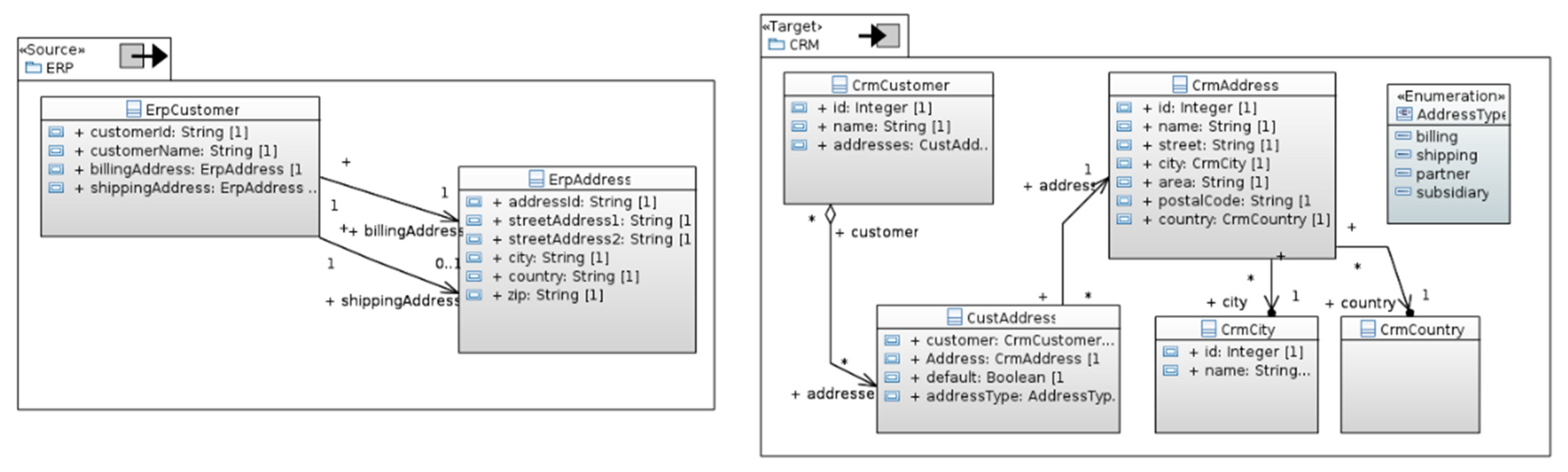
- Verification of prerequisites: as described in Section 4.1 (Overview), API documentation, process description, and a (relational) data model existed. Figure 8 shows the data models of the source system (ERP) and the target system (CRM);
- Identification data integration tasks: the data integration in this example was uni-directional, transactional, and in real-time (in practice, a question should be raised as to whether the data integration would be better as bi-directional, because both systems (ERP and CRM) are operational application systems where data can be created and modified. However, this discussion is outside the scope of this paper). The main data integration tasks were:
- (a)
- Transfer of customer master data from ERP to CRM;
- (b)
- Transfer of customer addresses ERP to CRM;
- (c)
- Creation of classification of customer addresses: billing (invoice) or shipping (delivery).
- Test scenarios and test cases (1): the processes, data structures, and data integration tasks were clarified on a level that allowed us to specify the test scenarios and commence the creation of the test case;
- Analysis, break down, and specification of data integration tasks in connection with communication and messaging: The data integration tasks from step 3 were of simple or medium complexity.
- The performance of a simple mapping for the following properties: “id” (see task a), “streetAddress1”, and “zip”. The property “streetAddress2” could be mapped to “area” (but this might need further analysis);
- For the properties “city” and “country”, the corresponding objects in the target system needed to be found prior to them being assigned to CrmAddress object properties. If a city or country was not found, it must be created.
- For a billing address in an object of ErpCustomer, a CustAddress object must be created and the address type set to “billing”. Proceed analogously for the shipping address;
- The object for CrmAddress determined based on the billing or shipping address in the ErpCustomer object and the address set in the CustAddress object;
- The newly created CustAddress object added to the list of addresses of the CrmCustomer object.
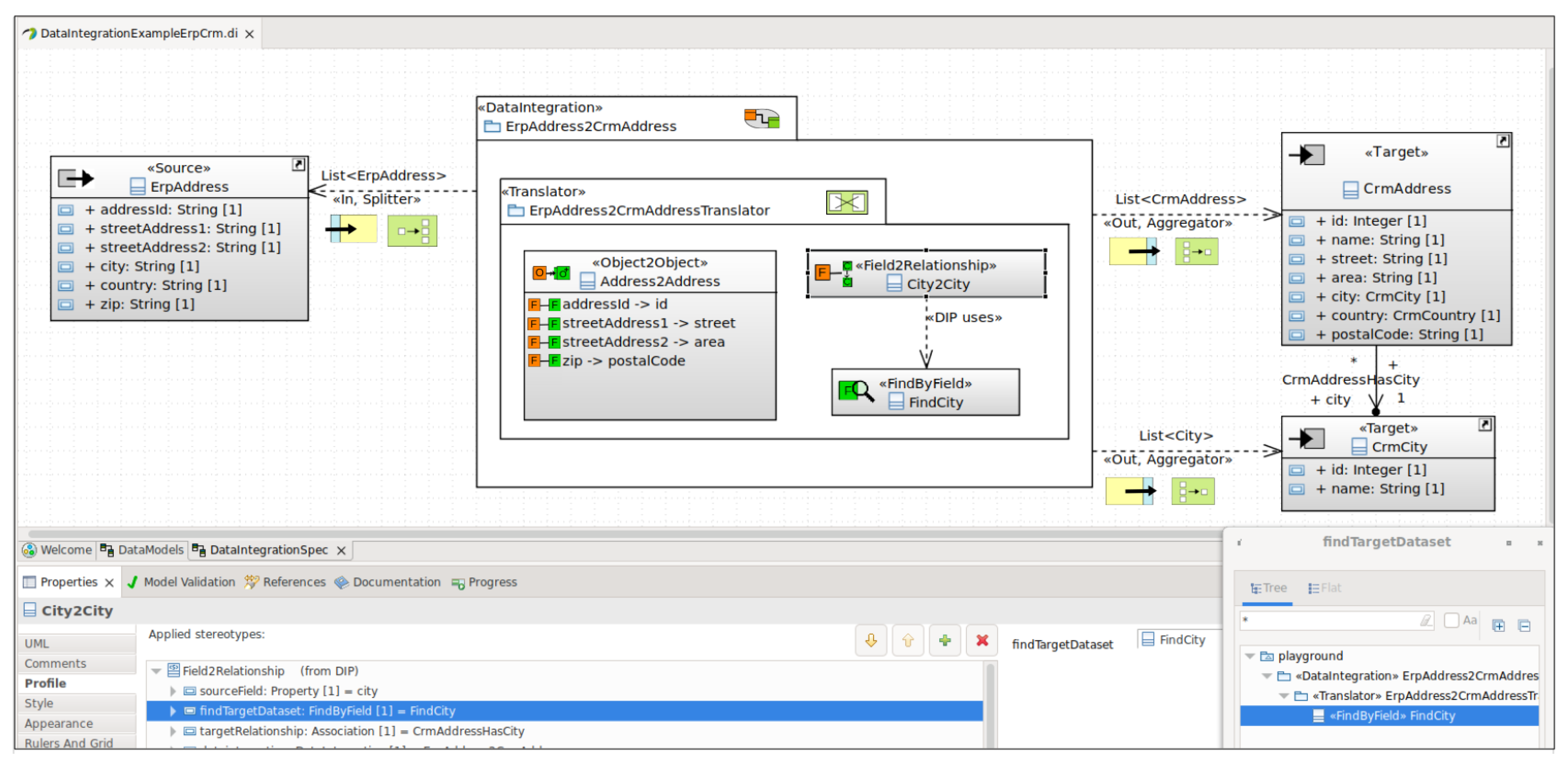
4.3.2. Data Integration Specification
- 7.
- Application of EIPs and DIPs: for the analyzed and specified data integration tasks, various EIPs and DIPs can be used;
- 8.
- Test scenarios and test cases (2): After finishing step 7, the details should be sufficient so that the test case creation can be finalized and test data can be generated or manually created. In addition, the testbed should be implemented (not described here).
4.4. Data Integration Implementation
5. Conclusions
- Code generation: With OMG’s MDA or other model-based software development techniques, the data integration specification can be considered a PIM (platform independent model) that can be transformed into a PSM (platform specific model) and to executable code (PSI, platform specific implementation). The generated code is a ready-to-be-used middleware for data integration based on Apache Camel and the DIP engine provided by the authors;
- Simulation: a simulator can take the data integration specification, generate test data (or real data) as an input, and create the output giving valuable information about the validity of the specification;
- Testing: test data and a test environment can be generated based on the specification, saving time and effort for the quality assurance tasks.
- The pattern catalog for data integration patterns must be extended. Additionally, the DIP engine that applies mapping specifications to real-world data integration scenarios needs more features. The visual editor for the graphical modeling requires a redesign. A community is needed in order to develop the necessary artifacts;
- Standards such as OMG’s model driven message interoperability (MDMI, [43]) should be considered and used for the metamodel of the data integration approach presented here. Constraint and consistency rules should be defined or visualized. OCL could be helpful for this task. The question here, is whether the experts accept these standards;
- More research for the methodology is necessary in order to provide guidelines in the context of real-life projects, e.g., the setup of an EDM (enterprise data management), tasks in the context of data migration, and development of microservices;
- Data quality and data cleansing are crucial aspects for data integration projects. These topics should be addressed in future work. A discussion with experts from different domains is crucial;
- Additionally, further research is necessary for the messaging and process-oriented aspects: the logic for the message passing had to be programmed in Java. Modeling the process (message passing), such as the chain of translators, splitters, and aggregators and using a process or workflow engine could add the necessary flexibility.
Author Contributions
Funding
Institutional Review Board Statement
Informed Consent Statement
Data Availability Statement
Conflicts of Interest
References
- Wagner, B.; Monk, E. Enterprise Resource Planning, 3rd ed.; Cengage Learning: Boston, MA, USA, 2008. [Google Scholar]
- Data Integration. Available online: https://dataintegration.info/data-integration (accessed on 15 July 2021).
- Zacharewicz, G.; Daclin, N.; Doumeingts, G.; Haidar, H. Model Driven Interoperability for System Engineering. Modelling 2020, 1, 94–121. [Google Scholar] [CrossRef]
- Chen, D.; Daclin, N. Framework for Enterprise Interoperability. In Proceedings of the IFAC Workshop EI2N, Loria, France, 12 July 2006; pp. 77–88. [Google Scholar]
- Petrasch, R. Data Integration Patterns in the Context of Enterprise Data Management. In Recent Advances in Information and Communication Technology 2018, Proceedings of the 14th International Conference on Computing and Information Technology (IC2IT 2019), Bangkok, Thailand, 4–5 July 2019; Unger, H., Sodsee, S., Meesad, P., Eds.; Springer: Berlin/Heidelberg, Germany, 2019. [Google Scholar]
- Object Management Group; Model Driven Architecture (MDA). MDA Guide rev. 2.0, OMG Document ormsc/2014-06-01. 2014. Available online: https://www.omg.org/cgi-bin/doc?ormsc/14-06-01 (accessed on 21 February 2022).
- Petrasch, R.; Meimberg, O. Model Driven Architecture—Eine Praxisorientierte Einführung in die MDA; Dpunkt.Verlag: Heidelberg, Germany, 2006. [Google Scholar]
- OMG (Object Management Group). OMG Unified Modeling Language (OMG UML), Version 2.5.1, Document Formal/2017-12-05. 2017. Available online: https://www.omg.org/spec/UML/2.5.1/PDF (accessed on 21 February 2022).
- Shervin Ostadzadeh, S.; Shams Aliee, F.; Arash Ostadzadeh, S. An MDA-Based Generic Framework to Address Various Aspects of Enterprise Architecture. In Advances in Computer and Information Sciences and Engineering, Proceedings of the 2007 International Conference on Systems, Computing Sciences and Software Engineering (SCSS), Bridgeport, CT, USA, 3–12 December 2007; Springer: Berlin/Heidelberg, Germany, 2007. [Google Scholar]
- OMG (Object Management Group). MOF Model to Text Transformation Language; Version 1.0, Document Formal/2008-01-16. January 2008. Available online: https://www.omg.org/spec/MOFM2T/1.0/PDF (accessed on 21 February 2022).
- Eclipse Foundation. Obeo Acceleo Project Website. Available online: https://www.eclipse.org/acceleo/ (accessed on 12 September 2021).
- IBM. Rational Software Architect Documentation, Vers. 9.7: Specifying Stereotypes and Constraints for Custom UML Profiles. Available online: https://www.ibm.com/docs/en/rational-soft-arch/9.7.0?topic=metamodel-specifying-stereotypes-constraints (accessed on 15 December 2021).
- Petrasch, R. DIP Github Repository. Available online: https://github.com/rpetrasch/DIP (accessed on 4 February 2022).
- Hohpe, G.; Woolf, B. Enterprise Integration Patterns: Designing, Building, and Deploying Messaging Solutions; Addison-Wesley: Boston, MA, USA, 2012. [Google Scholar]
- Apache Foundation. Apache Camel. Available online: https://camel.apache.org (accessed on 1 February 2019).
- Halevy, A.; Doan, A.; Ives, Z. Principles of Data Integration; Elsevier/Morgan Kaufmann: Burlington, MA, USA, 2012. [Google Scholar]
- Reeve, A. Managing Data in Motion: Data Integration Best Practice Techniques and Technologies. In The Morgan Kaufmann Series on Business Intelligence; Morgan Kaufmann: Burlington, MA, USA, 2013. [Google Scholar]
- Mulesoft. Top Five Data Integration Patterns. Available online: https://www.mulesoft.com/resources/esb/top-five-data-integration-patterns (accessed on 12 December 2021).
- Majkić, Z. Big Data Integration Theory: Theory and Methods of Database Mappings; Springer: Berlin/Heidelberg, Germany, 2014. [Google Scholar]
- Rahm, E. Data Integration in the Life Sciences. In Proceedings of the First International Workshop (DILS 2004), Leipzig, Germany, 25–26 March 2004. [Google Scholar]
- Blokdyk, G. Data Integration Patterns a Complete Guide—2020 Edition; 5STARCooks: Plano, TX, USA, 2019. [Google Scholar]
- Modelmapper Website. Available online: http://modelmapper.org/; https://github.com/modelmapper/modelmapper (accessed on 12 December 2021).
- Jitterbit Website: Products “Harmony” and “B2B/EDI Integration”. Available online: https://www.jitterbit.com/ (accessed on 12 December 2021).
- ZadahmadJafarloua, M.; Moeinib, A.; YousefzadehFarda, P. New Process: Pattern-Based Model Driven Architecture; Procedia Technology; Elsevier: Burlington, MA, USA, 2012; Volume 1, pp. 426–433. [Google Scholar]
- Hruby, P. Model-Driven Design Using Business Patterns; Springer: Berlin/Heidelberg, Germany, 2006. [Google Scholar]
- Kendle, N. The Enterprise Data Model. 2005. Available online: https://tdan.com/the-enterprise-data-model/5205 (accessed on 1 October 2021).
- Richardson, C. Microservices Patterns: With Examples in Java, 1st ed.; Manning: Shelter Island, NY, USA, 2018. [Google Scholar]
- Blaha, M. Patterns of Data Modeling; CRC Press: Boca Raton, FL, USA, 2010. [Google Scholar]
- Lenzerini, M. Data integration: A theoretical perspective. In Proceedings of the Twenty-First ACM SIGMOD-SIGACT-SIGART Symposium on Principles of Database Systems (PODS ’02), Madison, WI, USA, 3–5 June 2002; pp. 233–246. [Google Scholar]
- Evans, E. Domain-Driven Design: Tackling Complexity in the Heart of Software, 1st ed.; Addison-Wesley Professional: Boston, MA, USA, 2003. [Google Scholar]
- Fowler, M. Bounded Context. 2014. Available online: https://martinfowler.com/bliki/BoundedContext.html (accessed on 13 September 2021).
- Khononov, V. What Is Domain-Driven Design? O’Reilly Media Inc.: Sebastopol, CA, USA, 2019; Available online: https://www.oreilly.com/library/view/what-is-domain-driven/9781492057802/ch04.html (accessed on 2 September 2021).
- Price, E.; Buck, A.; Kshirsagar, D.; Sherer, T.; Boeglin, A.; Stanford, D. Identifying Microservice Boundaries. Available online: https://docs.microsoft.com/en-us/azure/architecture/microservices/model/microservice-boundaries (accessed on 12 October 2021).
- Sumathi, S.; Esakkirajan, S. Fundamentals of Relational Database Management Systems; Springer Science & Business Media: Berlin/Heidelberg, Germany, 2007. [Google Scholar]
- Lee, R.C.; Tepfenhart, W.M. Practical Object-Oriented Development with UML and Java; Prentice Hall: Hoboken, NJ, USA, 2002. [Google Scholar]
- Papazoglou, M.; Spaccapietra, S.; Tari, Z. Advances in Object-oriented Data Modeling; MIT Press: Cambridge, MA, USA, 2000. [Google Scholar]
- Fowler, M. Refactoring: Improving the Design of Existing Code, 2nd ed.; Addison-Wesley Professional: Boston, MA, USA, 2018. [Google Scholar]
- Gamma, E.; Helm, R.; Johnson, R.; Johnson, R.E.; Vlissides, J. Design Patterns: Elements of Reusable Object-Oriented Software; Addison-Wesley Professional Computing: Boston, MA, USA, 1994. [Google Scholar]
- Ponniah, P. Data Warehousing Fundamentals for IT Professionals, 2nd ed.; Wiley: Hoboken, NJ, USA, 2010. [Google Scholar]
- Kimball, R.; Caserta, J. The Data Warehouse ETL Toolkit: Practical Techniques for Extracting, Cleaning, Conforming, and Delivering Data, 1st ed.; Wiley: Hoboken, NJ, USA, 2004. [Google Scholar]
- OMG (Object Management Group). Object Constraint Language (OMG OCL) Version 2.4, Document Formal/14-02-03. 2014. Available online: https://www.omg.org/spec/OCL/2.4/PDF (accessed on 21 February 2022).
- Hohpe, G. Enterprise Integration Patterns. Available online: https://www.enterpriseintegrationpatterns.com (accessed on 21 August 2021).
- OMG (Object Management Group). Model Driven Message Interoperability (MDMI). v2.0—Beta 1, Document Number: Dtc/2021-01-02. 2021. Available online: https://www.omg.org/spec/MDMI/2.0/Beta1/PDF (accessed on 21 February 2022).
- OMG (Object Management Group). Meta Object Facility 2.0 Query/View/Transformation (QVT). Version 1.3, Document Number Formal/16-06-03. 2016. Available online: https://www.omg.org/spec/QVT/1.3/PDF-QVT/ (accessed on 21 February 2022).
- Li, Y.-F.; Zhang, H. Integrating software engineering data using semantic web technologies. In Proceedings of the 8th Working Conference on Mining Software Repositories, Honolulu, HI, USA, 21–22 May 2011; Van Deursen, A., Xie, T., Zimmermann, T., Eds.; Association for Computing Machinery: New York, NY, USA, 2011; pp. 211–214. [Google Scholar]


| Pattern Name | Icon | Description |
|---|---|---|
| Field-to-Field |  | A field of a relation (or class) maps to a field of another relation or class. |
| Merge Fields |  | Multiple field values are merged into one single field value. |
| Split Field |  | A single field value that contains multiple data elements is split into values for other different fields. |
| Aggregate Field |  | A field value is aggregated and stored in another field. |
| Convert-Field-to-Enumeration |  | A field value is used to determine an enumeration literal. |
| Relations-to-Inheritance-Tree |  | Data from a group of relations is mapped to objects of an OO inheritance tree. |
| Object-to-Object |  | A data object (data set, row, class instance) is mapped to another object (implies field mappings, see Field-to-Field pattern). The plus symbolizes that new objects are created if they do not exist. |
| Relations-to-Association-Class |  | Data from relations are mapped into objects (with an n:m association and an association class). |
| Extract-Fields-to-Class |  | A group of fields in one or more relations maps to an object of a class. |
| Field-to-Relationship |  | A field value is used to create a relationship (or association) between objects. |
| Target-object-to-relationship |  | An object of the target data model is used as a reference. A new relationship must be created in an object of a class (or relation). |
| Pattern Name | Split Field |  |
|---|---|---|
| Description | A single field value that contains merged data or multiple data elements is split into values for separate fields. | |
| Also Known As | Compound Field Split, Normalize Field Data, Demerge Field Value | |
| Classifications |
| |
| Problem/Motivation | A field from a source data element contains more than one chunk of information. Therefore, these chunks or parts must be transferred into different fields of a target data element. This happens, for instance, with denormalized data or semi-structured data. | |
| Solution | The field value of the source data elements must be split so that the parts can be extracted and transferred separately as field values of the target data element fields. Splitting is performed depending on the data type, format, and structure:
| |
| Consequences | The rules for field splitting can be complex and error-prone. Especially in the case of poor data quality, splitting can run into error situations that need to be addressed. Constraints and data quality rules for the target field might need to be checked first. | |
| Sample Model | The example below (domain: clothing) shows the source element (class “ErpProduct”, property “category”) on the left side and the target elements (class “CrmProduct”, properties “quality”, “family”, and “size”) on the right side. Packages, classes, and properties are marked as source and target, respectively, but property marking would have been sufficient in this case. The DIP application is shown in the middle: a split field pattern is applied to the source field “category” (product); the source field value is split into three target field values: “quality”, “family”, and “size”.  | |
| Sample Code (Java) | On the left side, the two classes “ErpProduct” and “CrmProduct” are defined (Lombok is used for constructor, getter, and setter code generation). On the right side, the DI within the Camel route is implemented: the field splitting is defined in the upper part of the configure method (object “diProductCategorySplit”) with the Java DSL for DIP and then embedded into an Apache Camel [15] route (route name “erpProduct2crmProduct”). | |
| @NoArgsConstructor @Getter @Setter public class ErpProduct { protected Integer id; protected String name; protected String category; } … @NoArgsConstructor @Getter @Setter public class CrmProduct { protected Integer id; protected String name; protected ProductQuality quality; protected String family; protected Size size; } … | public void configure() { DI diProductCategorySplit = diBuilder .layer(Layer.ApplicationSystem) .service(this) .mapping(SfMappingBuilder.class) .algorithm(SplitAlgorithm.Delimiter, “_”) .source(ErpProduct.class.getMethod(“getCategory”)) .target(CrmProduct.class.getMethod(“setQuality”)) .target(CrmProduct.class.getMethod(“setFamily”)) .target(CrmProduct.class.getMethod(“setSize”)) .end(). build(); from(“direct:erpProduct”) .routeId(“erpProduct2crmProduct”) .setExchangePattern(ExchangePattern.InOnly) .process(diProductCategorySplit) .to(“direct:crmProduct”); }… | |
| Related patterns | If the target fields are not in one single data set or object, selectors and aggregators are needed. | |
| Pos. | Name | Source(s) | Target(s) | Activity | Description |
|---|---|---|---|---|---|
| (a) | Customer master data | ERP System: ErpCustomer | CRM System: CrmCustomer | Transfer all objects (one by one) | For every object of ErpCustomer, a new object of CrmCustomer is created. The properties id and name are transferred. For the address transfer, see task b. |
| (b) | Customer addresses | ERP System: ErpCustomer, ErpAddress | CRM System: CrmCustomer, CustAddress, CrmAddress, CrmCity. CrmCountry | 1. Transfer all objects from ErpAddress to CrmAddress (one by one) 2. For each billing and shipping address create CustAddress | 1. For every object of ErpAddress, a new object of CrmAddress is created. All properties are transferred. 2. For each value of billingAddress and shippingAddress a new object of CustAddress is created (referenced to the address). The correct addressType must be set (see task c). |
| (c) | Address type | ERP System: ErpCustomer | CRM System: CustAddress | Set the field value for addressType | During the creation of CustAddress objects (see b, 2.), the address type must be determined (depending on the source data) and set in the CustAddress object. |
| Process | Pos. | Name | Source(s) | Target(s) | Activity | Description |
|---|---|---|---|---|---|---|
| 1. Erp Customer Iteration | (a) | Customer master data | ERP System: ErpCustomer | CRM System: CrmCustomer | Transfer all objects | For every object of ErpCustomer, a new object of CrmCustomer is created. Properties id and name are transferred. |
| 2. Erp Address Iteration | (b) | Customer addresses | ERP System: ErpAddress | CRM System: CrmAddress | Transfer all objects | For every object of ErpAddress, a new object of CrmAddress is created. Properties id, streetAddress1, streetAddress2, and zip code are transferred. |
| (c) | City and Country for customer address | ERP System: ErpAddress | CRM System: CrmAddress, CrmCity. CrmCountry | Set properties | Find city and country in the target system and assigned to CrmAddress object. If a city or country is not found it must be created. | |
| 3. Erp Customer Iteration: billing/shipping address | (d) | Association object for customer and address | ERP System: ErpCustomer | CRM System: CustAddress | Transfer all objects | Create CustAddress object for each billing and shipping address and set the address type |
| (e) | Set the address in the association object | ERP System: ErpCustomer | CRM System: CrmAddress, CustAddress | Set properties | Determine CrmAddress object. Set the address in the CustAddress object. | |
| (f) | Add association object to customer address list | ERP System: ErpCustomer | CRM System: CrmCustomer, CustAddress | Add object to list | Add CustAddress object to list of addresses. |
| Process | Pos. | Name | EIP | DIP | Description | |
|---|---|---|---|---|---|---|
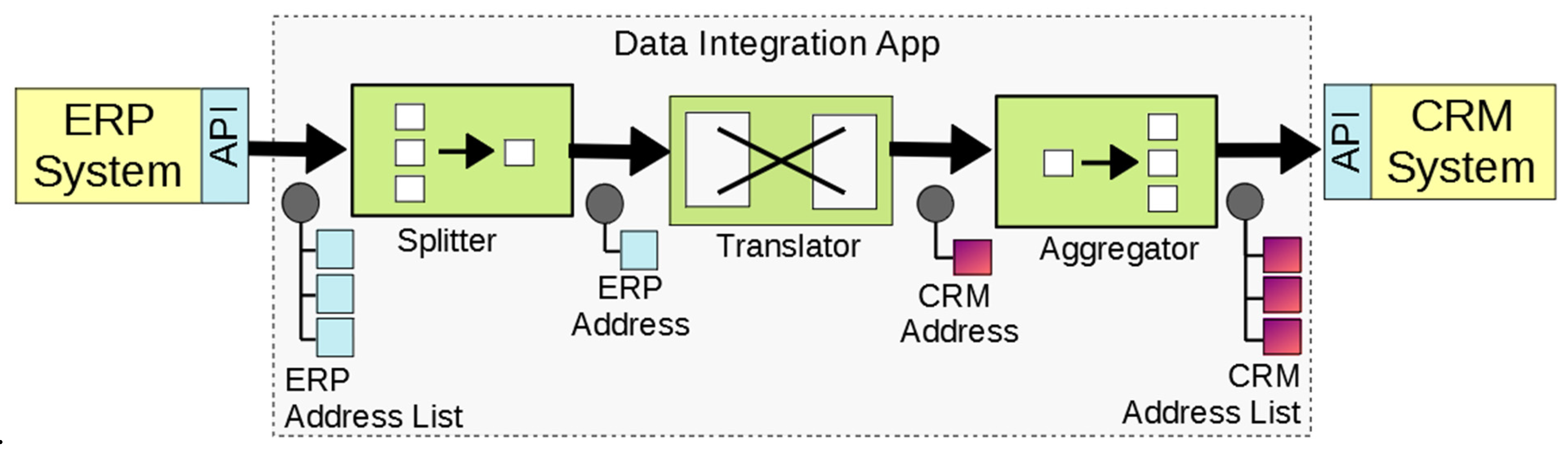
| 1. ERP Address Iteration | (a) | Customer addresses | Splitter Translator  | Object-to-Object Field-to-Field  | A splitter EIP allows the data integration logic to process each customer address separately. Object-to-Object and Field-to-Field DIPs are applied (in the context of the Translator EIP) for the address object (the plus on the target side means that new objects are created). | |
| (b) | City and Country for customer address | Translator | Aggregator | Field-to-Relationship | A Field-to-Relationship DIP processes a field value, e.g., a foreign key, and finds an object of a relation or class in the target data model. It then creates a reference to that object in another target object. An aggregator EIP combines the addresses to a list that is delivered to the recipient. | |
 |  | |||||
| 2. ERP Customer Iteration | (c) | Customer master data | Splitter Translator | Object-to-Object Field-to-Field  | A customer list is split into single objects with the EIP splitter. Customer objects are created with Object-to-Object and Field-to-Field DIPs. | |
| (d) | Association object for customer and address | Splitter Translator | Object-to-Object Field-to-Field  | A customer has to be split (EIP splitter): billing and shipping address are processed (Translator EIP). For each address a new object (Object-to-Object DIP) is created with field mappings (Field-to-Field DIP). | ||
| (e) | Set the address in the association object | Translator | Field-to-Relationship | A customer has to be split (EIP splitter): billing and shipping address are processed (Translator EIP). For each address a new object (Object-to-Object DIP) is created with field mappings (Field-to-Field DIP). | ||
| (e) | Add association object to customer address list | Translator | Aggregator | Target-Object-to-Relationship | The address–customer object must be added to the customer’s addresses list. A Target-Object-to-Relationship DIP is used for this purpose. An aggregator EIP collects all customers and combines them into one single message for the recipient. | |
 |  | |||||
| EIP | DIP | Generated Code (Implementation) |
|---|---|---|
 | public void configure() throws Exception { //DI object creation with applied DIPs for data integration DI diErpAddress2CrmAddress = diBuilder .layer(Layer.ApplicationSystem) .service(this) .mappingObject2Object(true)//a) DIP Object-to-Object for customer addresses .source(ErpAddress.class) .target(CrmAddress.class) | |
 | .mappingsFF()//DIPs Field-to-Field .map(“addressId”, “id”) .map(“streetAddress1”, “street”) .map(“streetAddress2”, “area”) .map(“zip”, “postalCode”) .endMapping() | |
 | .mappingField2Relationship()//b) DIP Field-to-Relationship for cities .map(“city”, “city”) .find(City.class, “cities”, “name”) .endMapping() .mappingField2Relationship()//b) DIP Field-to-Relationship for countries .map(“country”, “country”) .find(Country.class, “countries”, “name”) .endMapping() .endMapping() .build(); | |
 | from(“direct:erpAddresses”)//Apache Camel route (EIP) .routeId(“erpAddresses”) .setExchangePattern(ExchangePattern.InOnly) .split(body(), new AddressAggregationStrategy())//EIP splitter and aggregator .process(diErpAddress2CrmAddress)//EIP translator with DI object .to(“direct:crmAddresses”); } |
Publisher’s Note: MDPI stays neutral with regard to jurisdictional claims in published maps and institutional affiliations. |
© 2022 by the authors. Licensee MDPI, Basel, Switzerland. This article is an open access article distributed under the terms and conditions of the Creative Commons Attribution (CC BY) license (https://creativecommons.org/licenses/by/4.0/).
Share and Cite
Petrasch, R.J.; Petrasch, R.R. Data Integration and Interoperability: Towards a Model-Driven and Pattern-Oriented Approach. Modelling 2022, 3, 105-126. https://doi.org/10.3390/modelling3010008
Petrasch RJ, Petrasch RR. Data Integration and Interoperability: Towards a Model-Driven and Pattern-Oriented Approach. Modelling. 2022; 3(1):105-126. https://doi.org/10.3390/modelling3010008
Chicago/Turabian StylePetrasch, Roland J., and Richard R. Petrasch. 2022. "Data Integration and Interoperability: Towards a Model-Driven and Pattern-Oriented Approach" Modelling 3, no. 1: 105-126. https://doi.org/10.3390/modelling3010008