Article

Waterproof Design of Soft Multi-Directional Force Sensor for Underwater Robotic Applications

by
Liam B. Cross
1,†,
Rafsan Al Shafatul Islam Subad
1,†,
Md Mahmud Hasan Saikot
2 and
Kihan Park
1,*
1
Department of Mechanical Engineering, University of Massachusetts Dartmouth, 285 Old Westport Road, Dartmouth, MA 02747, USA
2
Department of Mechanical Engineering, Bangladesh University of Engineering and Technology, Dhaka 1000, Bangladesh
*
Author to whom correspondence should be addressed.
These authors contributed equally to this work.
Appl. Mech. 2022, 3(3), 705-723; https://doi.org/10.3390/applmech3030042
Submission received: 20 May 2022 / Revised: 17 June 2022 / Accepted: 19 June 2022 / Published: 22 June 2022
(This article belongs to the Special Issue Feature Papers in Applied Mechanics)

Abstract

:
Directional force sensing is an intrinsic feature of tactile sensing. As technologies of exploratory robots evolve, with special emphasis on the emergence of soft robotics, it is crucial to equip robotic end-effectors with effective means of characterizing trends in force detection and grasping phenomena, while these trends are largely derived from networks of tactile sensors working together, individual sensors must be built to meet an intended function and maintain functionality with respect to environmental operating conditions. The harshness of underwater exploration imposes a unique set of circumstances onto the design of tactile sensors. When exposed to underwater conditions a tactile sensor must be able to withstand the effects of increased pressure paired with water intrusion while maintaining computational and mechanical integrity. Robotic systems designed for the underwater environment often become expensive and cumbersome. This paper presents the design, fabrication, and performance of a low-cost, soft-material sensor capable of multi-directional force detection. The fundamental design consists of four piezo-resistive flex elements offset at 90 increments and encased inside of a hemispherical silicone membrane filled with a non-compressive and non-conductive fluid. The sensor is simulated numerically to characterize soft-material deformation and is experimentally interrogated with indentation equipment to investigate sensor-data patterns when subject to different contact forces. Furthermore, the sensor is subject to a cyclic loading test to analyze the effects of hysteresis in the silicone and is submerged underwater for a 7-day period to investigate any effect of water intrusion at a shallow depth. The outcome of this paper is the proposed design of a waterproofed, soft-material tactile sensor capable of directional force detection and contact force localization. The overall goal is to widen the scope of tactile sensor concepts outfitted for the underwater environment.

1. Introduction

The complexity of a human hand can be characterized by the ability to articulate intricate mechanical motions paired with the ability to recognize shape, gripping forces, and shearing motions of an object through grasping and other general motions. Without any sort of visual information about the shape or physical composition of an object, a human can quickly decipher an object’s relative structure and inherently adapt to how the object should be picked up via hand interactions [1]. As is relative to the design of many robotics systems, there is a goal to closely mimic and replicate the capabilities of biological systems and their mechanical functions. Furthermore, there is a major effort to closely mimic the functionality of the human hand in robotic end-effector design. Optimal end-effector designs, with emphasis on soft robotic systems, are capable of grasping and manipulating a variety of objects while performing tasks in unstructured environments [2,3,4], while a soft robotic design framework allows end-effectors to more easily conform and adjust to a complex object’s form factor, there still remains a large degree of inaccuracy when articulating soft end-effectors in remote and uncontrolled environments, especially in the undersea environment [5,6,7]. Special applications for undersea remote operation of soft end effectors include delicate sample collection, explosive ordinance disposal (EOD), repair of underwater vehicles (UUVs), as well as any general task that requires contact with foreign objects [8,9,10]. In these types of applications, there are major benefits to utilizing haptic feedback gathered by tactile sensors to estimate an object’s shape and force interactions.
Based on current technologies, there are a handful of sensor implementations designed to characterize both normal force and multi-directional shear forces [1]. In a proof of concept, Lee et al. presented a method for capacitive force sensing capable of both normal and shear force detection with a sensor structure built from Polydimethylsiloxane (PDMS). The presented technology can measure up to 131 kPa of force in three directions [11]. Furthermore, other researchers also investigated capacitive tactile sensors to recognize trends in normal, and multi-directional shear forces in their respective works [12,13,14]. A flexible piezoelectric tactile sensor array based on the construction of polyvinylidene fluoride (PVDF) film is demonstrated which can measure three dimensions dynamic contact force distribution by Yu et al. [15]. Wolterink et al. presented a 3D-printed fingertip sensor that utilizes piezo-resistive sensing to measure up to 10 N force, both normal and shear [16]. Harada et al. presented a sensing method that leverages variable resistance readings to analyze interactions of touch, friction, and slipping. However, force interactions in this study were limited to one-directional movement due to the challenges imposed on fabricating the devices on flexible substrates [17]. Teshigawara et al. presented a sensor system that is capable of recognizing the trends of normal force, shear force, and slip detection for a multi-digit end-effector by utilizing pressure-sensitive, conductive rubber [18]. Other approaches such as the use of conductive textile in a sensor design that can detect normal and tangential forces, a magnetic microsensor used for reading braille which utilizes magnetic nanocomposite artificial cilia to recognize trends in normal and shearing surface contact, the GelSight tactile sensor which utilizes vision-based optical sensing to detect normal, shear, and torsional loads on a contact surface have also been exhibited [19,20,21], while all of the previously mentioned sensor technologies can characterize 2D dimensions forces, and in some cases 3D forces, there is still a common limitation that the sensors are not designed to operate underwater. Currently, the most prominent type of tactile sensing technology outfit for undersea operations is normal force sensing [22,23,24,25]. Brien et al. have demonstrated an underwater slip detection mechanism that utilizes Polyvinylidene Difluoride (PVDF) material to recognize the occurrence of slipping between a fingertip and target object interface previously [26]. However, these sensors are expensive, complex to manufacture, and inflexible in nature. Thus, there remains a critical need to develop cost-effective, soft, multi-directional force sensors integrable with soft robotic systems in order to identify multi-directional force trends underwater [27,28].
This paper presents the design, fabrication, and testing of a low-cost multi-directional force sensor designed for feasibility with a soft robotic framework geared toward underwater applications. The sensor is characterized by an array of four piezo-resistive flex elements nested at 90 increments inside of a semi-spherical soft material structure. The sensor is capable of detecting trends in normal force, multi-directional, and shear forces by recognizing exhibited patterns in the sensor array data. With the presence of a normal force, the four piezo-resistive flex elements exhibit a potential difference of homogeneous effect, whereas off-axis contact force and shearing force exhibit a consistent divergent pattern among the flex sensors, which depends on the location of the contact force on the soft hemisphere. Based upon the rugged construction of the multi-directional force sensor, it is speculated to perform well as a low-cost solution in underwater applications. The following M a t e r i a l s a n d M e t h o d s section will review the sensor design to provide insight into the characteristic advantages of its construction. Furthermore, a complete list of materials is provided with a comprehensive fabrication process so that the sensor can be re-created for future developments. The R e s u l t s section is split into sub-sections characterizing calibration, numerical simulation, cyclic load testing, hysteresis testing, and waterproof testing to model and showcase the performance of the sensor under conditions of normal and shear force, as well as its performance when submerged in water. Furthermore, the C o n c l u s i o n section will emphasize the novel takeaways of the design and how the soft material multi-directional force sensor is a novel inspiration for underwater tactile force sensing design. The explicit details for the construction are provided so that it can be extrapolated in future studies to expand tactile sensing capabilities outfit for underwater use-case. Thus, the overall goal of this report is to provide an effective, cost-effective, and provable implementation of multi-directional force sensing technology outfit for underwater applications.

2. Materials and Methods
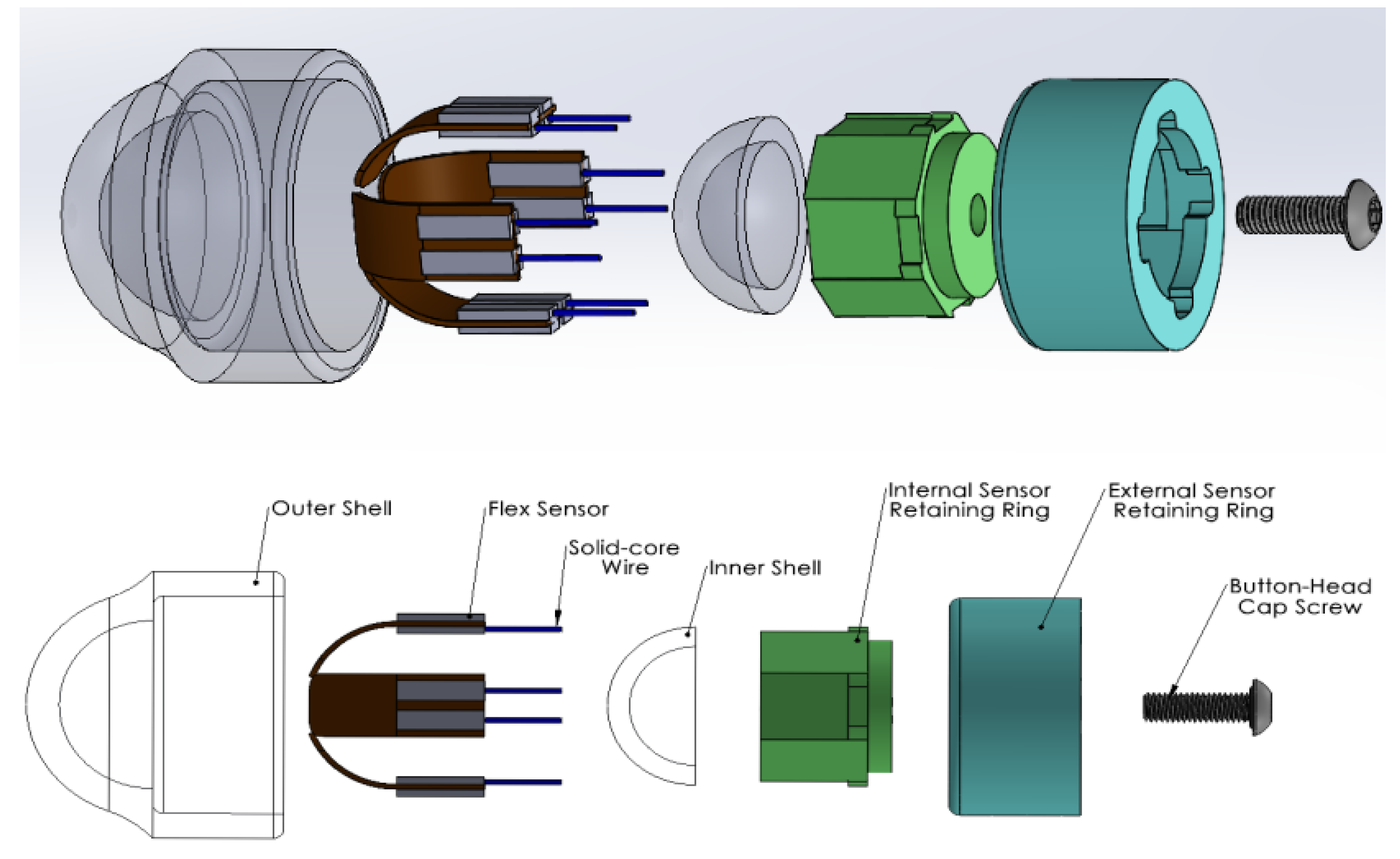
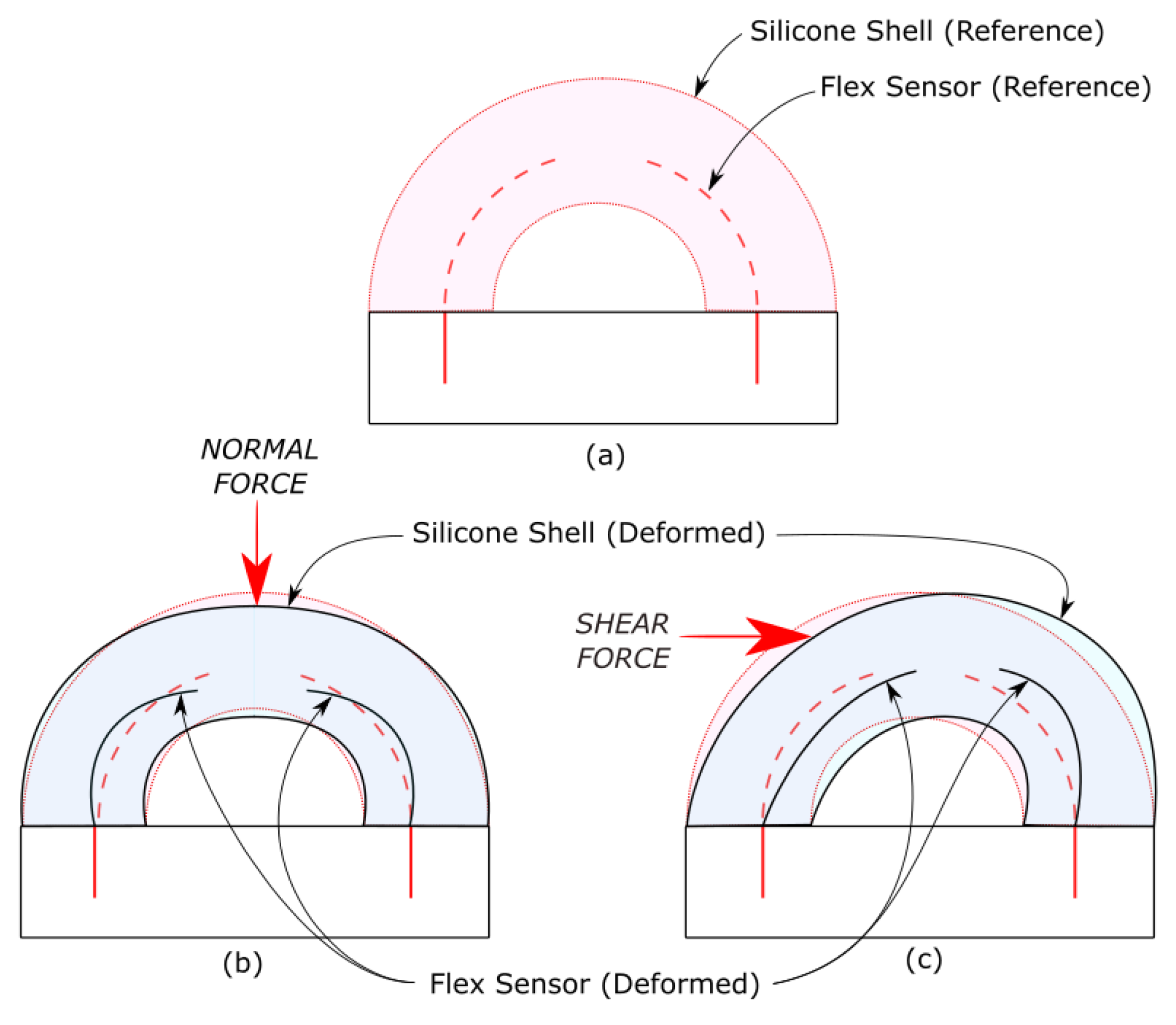
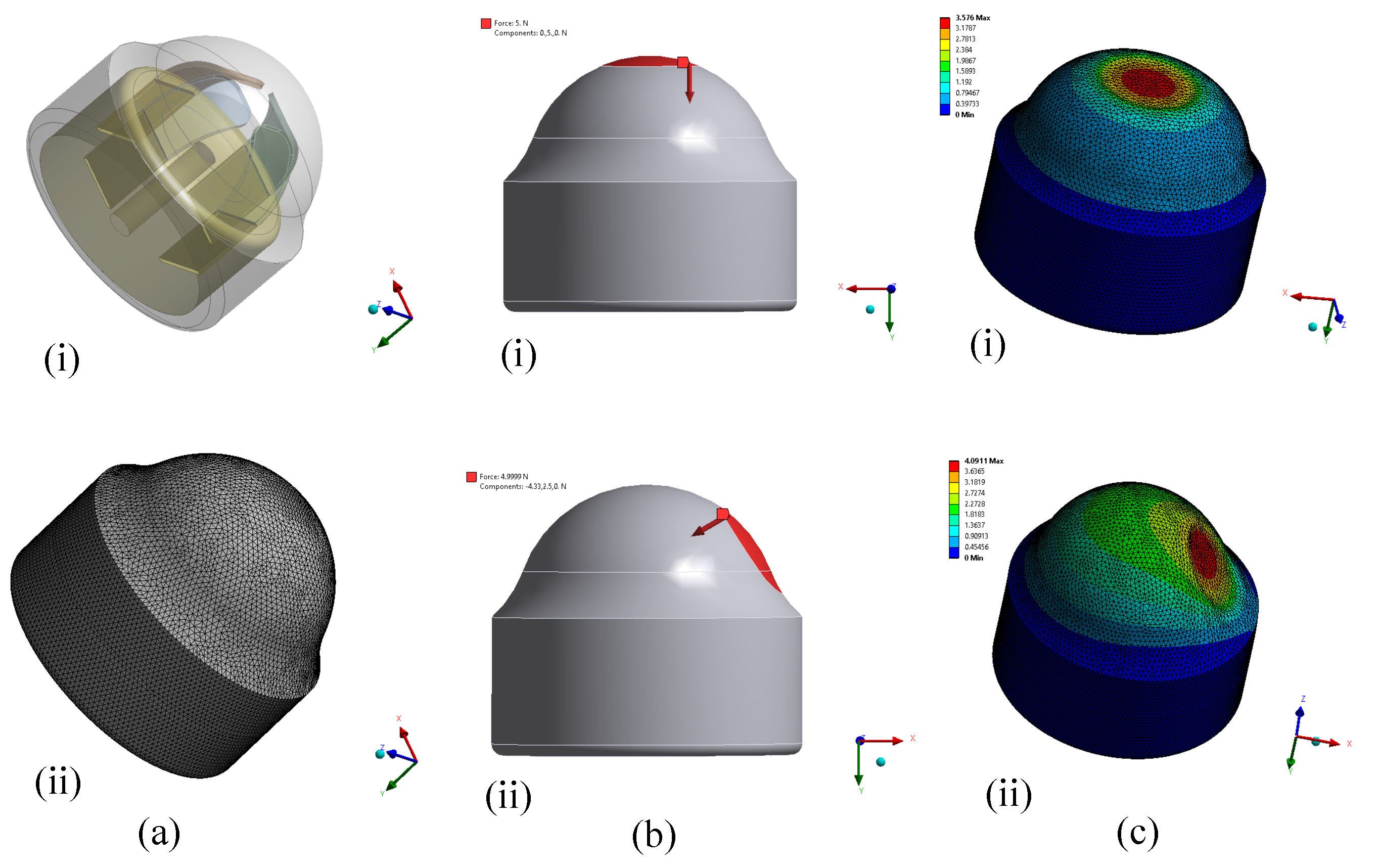
2.1. Design

The design of this sensor is based on the principles of attainable and low-cost materials to verify the effective performance of a multi-directional force sensing system that does not rely on high-expense equipment or complex components to yield proven results in characterizing trends in contact forces. The benefit of designing the sensor in this manner is to provide novel insight for new low-cost systems by demonstrating the feasibility of utilizing commonly available equipment such as piezo-resistive flex sensors. Piezo-resistive flex sensors operate on the principle of the piezo-resistive effect, which is a change in the electrical resistivity of a semiconductor when a mechanical strain is applied to an active sensing area. It should be noted that while electrical resistivity changes in a semiconductor the electrical potential stays the same. The proposed sensor design emphasizes the piezo-resistive effect and showcases the effectiveness of utilizing commonly available low-cost piezo-resistive flex sensors as a four-element array to characterize multi-directional force and shear force sensing. The flex sensors used in the design are Adafruit’s short flex sensors which are each modified to 17 mm in length. The compact sensor design emphasizes a rugged waterproofed construction that is fit for performance in underwater applications. The piezo-resistive flex sensors are nested at 90 incrementation inside of a silicone-based hemisphere as can be referenced to Figure 1. The silicone used for construction is a mix of Dragon Skin FX-Pro (DSFP) platinum cure silicone with added Slacker Silicone Tactile Mutator (both items from Reynolds Advanced Materials, Boston, MA, USA). The flex sensors are nested internally between an inner and outer shell with an overall thickness of 5.5 mm, as can be referenced in Figure 2. These components are listed as Items 1 and 4 in Table 1 and Figure 3. Each of the four flex sensors has an active sensing length of 10.079 mm, which is based upon a 70 span around an 8.25 mm reference circle. The electrical connections of the flex sensors are nested between an interior and exterior retaining ring (Items 5, 6 in Table 1 and Figure 3). The retaining rings are back-filled and bonded with a 2-part epoxy (Item 9 in Table 1 and Figure 3) to fuse the sensor array as a solid unit and fill any air gaps in the retaining ring interface. The overall dimension of the outer-ring is a 22 mm diameter by 12 mm height. Furthermore, the silicone shell structure wraps around the outer-ring causing the overall outer diameter of the assembly to extend to 27 mm. An internal pocket inside of the shell is filled with a non-conductive and incompressible fluid (Item 8, Table 1) and sealed with face-seal hardware (Item 7, Table 1) which extends through the center of the retaining ring interface. The internal fluid is used to preserve the effects of silicone material deformation but also to minimize the effects of compression during deep-water submersion. With a final layer of epoxy added to the top surface of the sensor (not shown in Figure 1, Figure 2 and Figure 3), the overall height of the sensor is ∼27 mm.
The potted wire-jackets extend from the top surface of the sensor where they extend beyond the scope of the sensor assembly. Thus, the overall design of the sensor provides a simple and waterproofed tactile multi-directional force sensor. Based upon the array or flex sensors positioned at 90 increments, the sensor can recognize trends in normal, multi-directional contact forces. Figure 4 provides a general visualization of how the soft material hemisphere deforms under normal and shear loads and the effect of each load on the flex sensors. Normal force phenomena are correlated with uniform deformation in the soft material shell which yields a consistent pattern in differential readings across each of the four flex sensors. Off-axis and shearing forces cause a divergent trend in the flex sensor readings, which scale proportionally with the magnitude of contact force present. Table 1 provides a complete materials list and a comprehensive overview of the fabrication process is provided in Section 2.2. The R e s u l t s section will showcase characteristic sensor data patterns when subject to normal and multi-directional force, as well as simulate the silicone construction of the sensor under normal and 60 off-axis loading. The sensor will be further inspected to review cyclic loading, a hysteresis test, and an underwater submersion test.

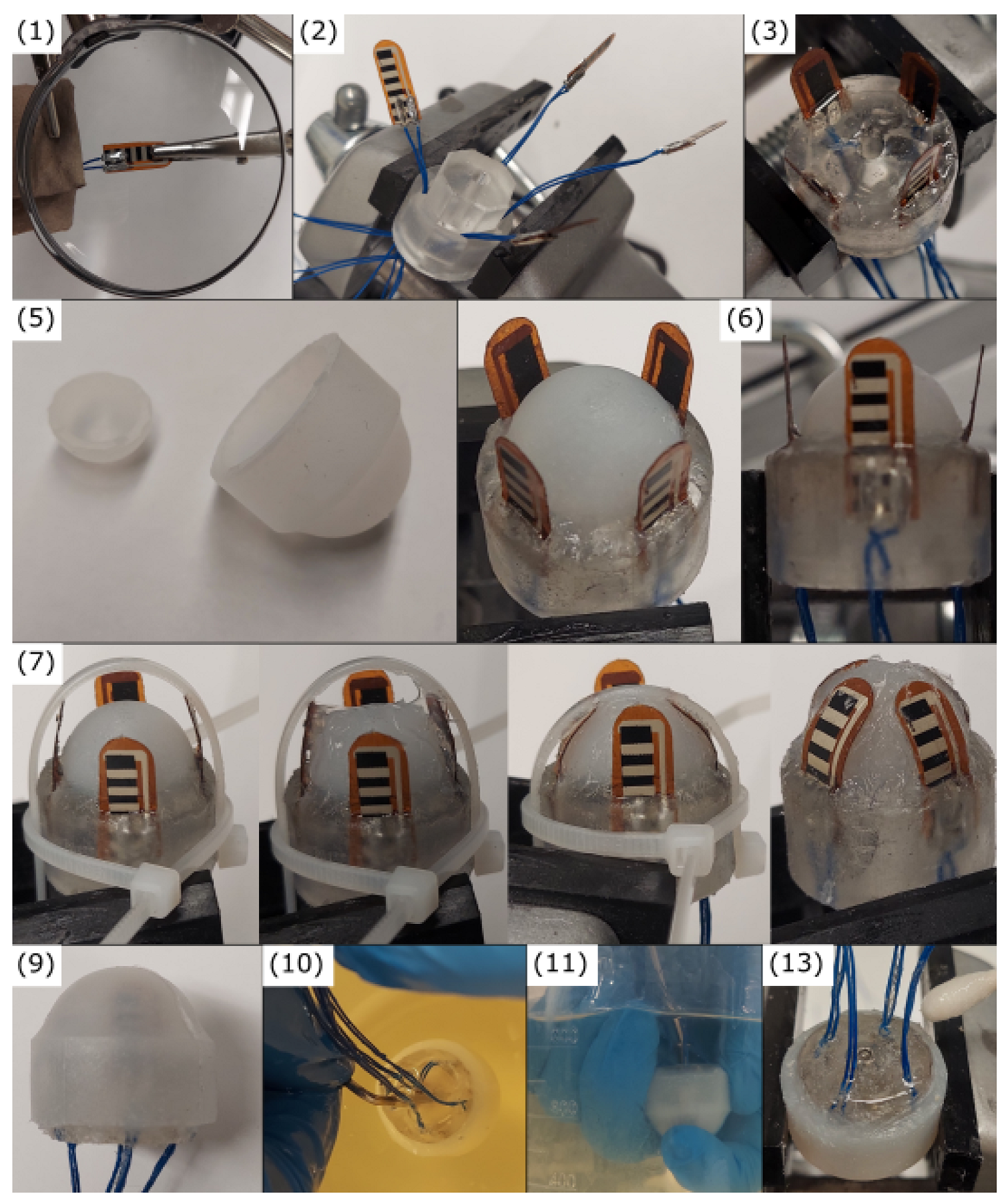
2.2. Fabrication Process

The following fabrication process provides sequential operations which were taken to realize a physical prototype of the multi-directional force sensor. It should be noted that all materials used for development are listed in Table 1.
  • Cut the flex sensors (Item 2) to a length of 17 mm. Add two clinch connectors and solder wire (Item 3) to the terminals.
  • Place the flex sensors inside of the internal and external retaining rings, carefully pulling the wires through.
  • Using DEVCON 2-part epoxy (5 Minute Epoxy, ITW Global Brands, Houston, TX, USA), back-fill the internal and external retaining ring interface. Ensure there are no-air gaps in the wire through-ways.
  • After the DEVCON epoxy has fully cured and the retaining rings are joined, tap an M3.5x0.6 thread through the center of the ring. (Note: This step is not shown visually).
  • Mold the outer shell (Item 1) and inner shell (Item 4) using DSFP platinum silicone and Slacker Silicone Tactile Mutator. Mix equal portions of DSFP 1A:1B with Slacker Silicone mutator to form mix ratio of 10:1 (Silicone:Mutator). Let the molds cure for 1.5 h each.
  • Adhere the inner shell onto the retaining ring interface using Sil-Poxy silicone adhesive (Sil-Poxy, Smooth-on, Macungie, PA, USA). Let the Sil-Poxy cure for 20 min.
  • Using Sil-Poxy, Adhere quantity 2 flex sensors in 180 alignments to the inner shell to establish default radius profiles. Use three thin zip-ties to restrict the movement of the flex sensors as shown in Figure 5. Apply the Sil-Poxy and then pull the zip-ties tight to keep the flex sensors in place during curing. Allow the Sil-Poxy to cure for 30 min.
  • Repeat step 7 with the remaining two flex sensors.
  • Carefully remove the zip-ties. Adhere the outer layer onto the inner layer using Sil-Poxy. Allow the Sil-Poxy to cure for 1 hour.
  • Place the force sensor into a small bucket of mineral oil (’ISO Grade 32’, McMaster-Carr, Elmhurst, IL, USA). Displace any air bubbles that are trapped internal to the sensor by filling the internal pocket with mineral oil. Use a small object such as a hex-wrench to force the air bubbles out considering the high viscosity of the mineral oil.
  • With the sensor displaced in the oil, insert the button head cap screw to seal the mineral oil into the internal pocket. It is critical to apply hardware while submersed in the mineral oil to avoid intrusion of air to the internal pocket.
  • Remove the sensor from the mineral oil, and place it into Isopropyl alcohol for 1 min. Clean the oil from the sensor surface with a q-tip taking extra care to remove residual oil from the top surface.
  • Add a final layer of DEVCON 2-part epoxy to the top surface of the sensor to fully encapsulate the sealing hardware.
  • Take extra care to label wires and bundle them together to ensure proper identification and preservation for further testing. The fabrication process is complete.

3. Experimental Results

3.1. Calibration of the Sensor
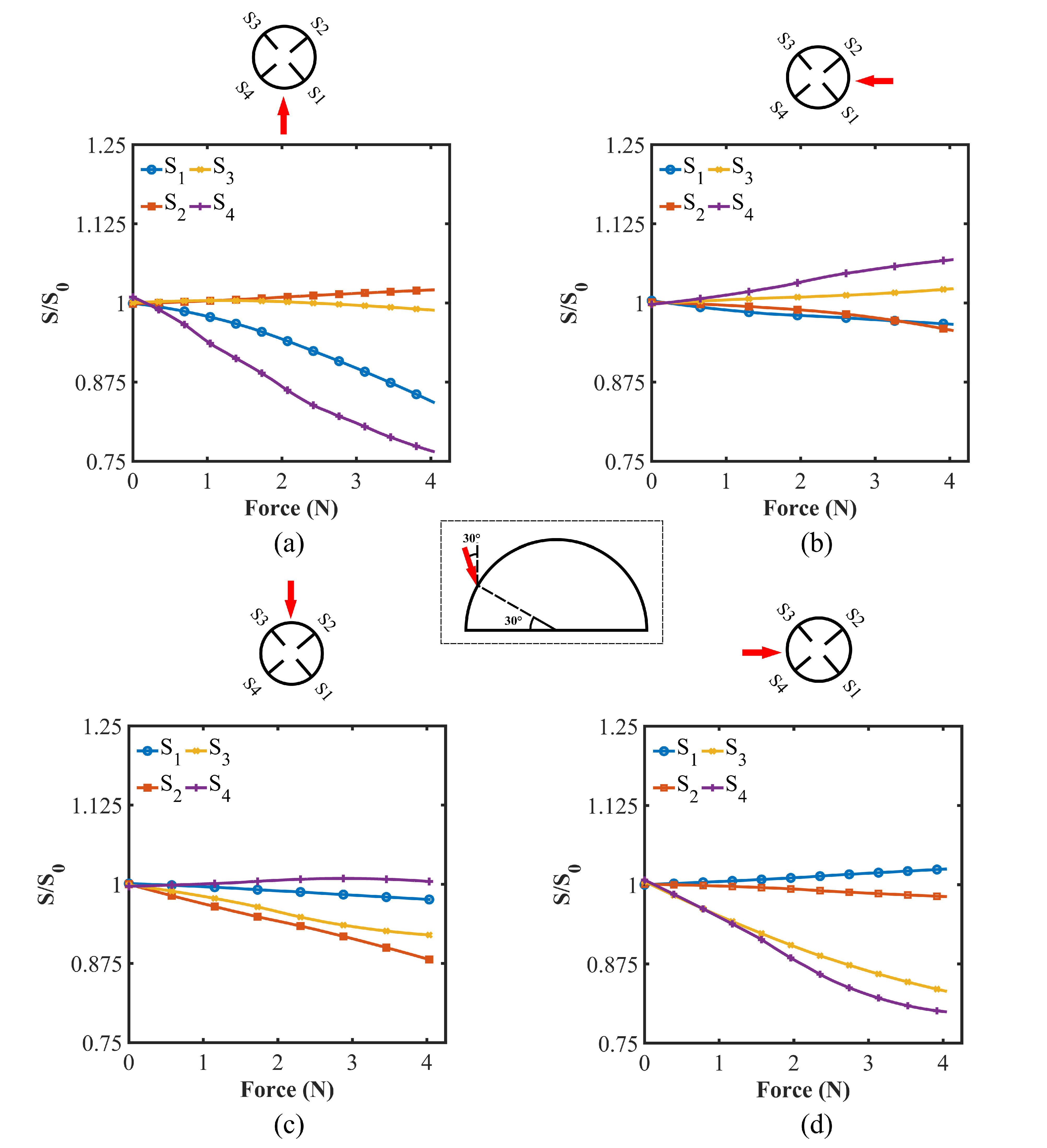
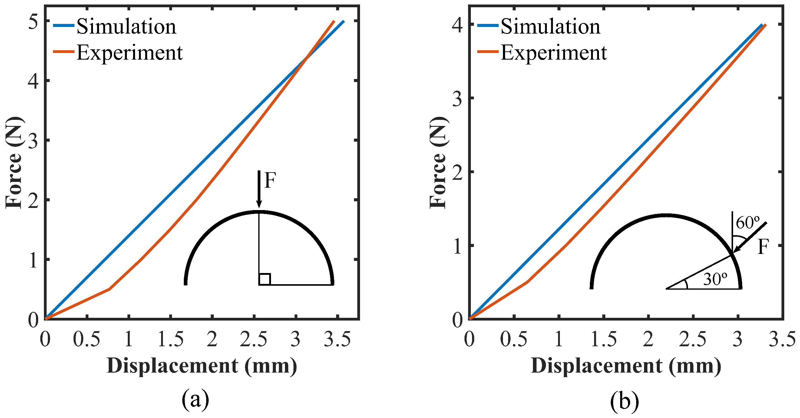
The sensor was calibrated for multi-directional force detection by using commercially available indentation equipment (AGS-X, Shimadzu, Japan) in congruence with a 10 N force gauge and 10 mm diameter indenter. The machine’s physical setup was operable for vertical testing, whereas, a custom fixture was used to align and mount the sensor at various angular offsets. Force calibration configurations for the force along with 0 and 60 to the vertical axis are shown in Figure 6. To obtain the differential output data from the sensors a simple voltage divider circuit was employed, as well as a Savitzky–Golay finite impulse response filter to smooth the output data into better quality data sets [29]. When applying a normal force at 0 inclination, all four of the flex sensors deformed homogeneously and yielded analogous differential phenomena. Figure 7 demonstrates the output data of the sensor when subject to normal force exerted at 0 inclination. The result for this case is consistent with the output of the sensor due to normal force built in our previous study [30]. It should be understood that each flex sensor’s differential reading is distinct from the others due to variable sensitivity and suitable positioning constraints during fabrication. Although the sensor ranges and initial values should be the same theoretically, they differ from one another due to manufacturing differences and geometric discrepancies in the bending angle of each sensor inside of the shell. However, the pattern exhibited by each of the flex sensors follow the same trend under exertion of a normal load. It is important to mention that the output data set for each flex sensor is divided by its respective initial value (when no force is applied) to yield dimensionless and normalized values. The initial values of sensors S 1 –S 4 as depicted (in the top view of the sensor) by Figure 7 were 175, 160, 180, and 120 mV, respectively. Despite the variability in flex sensor initial values and ranges, the limitations do not significantly affect the performance of the sensor virtually. By taking the slope of linear fitted data after averaging the four flex sensor data sets under normal force loading conditions, the sensitivity of the system appears to be ∼4 mV/N.
The sensor was also inspected at 30 and 60 inclination to the vertical axis, such that the indenter engaged with the silicone hemisphere as depicted in Figure 6b,c accordingly. Fixed at this angular offset, the sensor was rotated along its vertical axis to 8 incremental positions for both of the cases in order to capture data readings on all four flex sensors, S 1 –S 4 , in accordance with Figure 8 and Figure 9, and at 45 intervals between each of the other flex sensors, in accordance with Figure 10 and Figure 11. As shown in Figure 8 and Figure 9 accordingly, when force at 30 and 60 to the vertical axis is applied directly onto a certain sensor, the corresponding differential reading of that flex sensor is minimum with respect to the remaining three flex sensors. In previous tests reported in [30], an increase in the flex sensor under indentation was visible. This was due to a complete soft construction of the silicone pad, which allowed for the flex sensor base to move more in line with its active sensing length. However, by introducing the solid retaining ring to the updated sensor design the flex sensor’s base remains fixed when the active sensing length is displaced due to the deformation of the shell. Therefore, the readings exhibit a repeatable trend, but opposite to what was reported previously [30], while there does exist variability in readings between sensors S 1 –S 4 in the case of this reporting, there is a clear and repeated trend that provides emphasis that a contact force is localized to a specific sensor. Although flex sensor outputs should have been precisely similar theoretically as hypothesized in the working principle of the sensor, they are different for individual cases (demonstrated in Figure 7, Figure 8, Figure 9, Figure 10 and Figure 11). Limitations in fabrication such as not being able to place the flex sensors exactly at the orthogonal position, or not being able to keep all the flex sensors at the same level of bend in the hemispherical structure might be the reasons behind this discrepancy. It can also be explained by the fact that it is virtually impossible to cut all the flex sensors exactly at the same length, or their sensitivity might vary during their manufacturing process. Thus, pragmatically, it is highly likely that their outputs will differ from one another for the same level of input. However, it is important to mention that their trends of change due to certain types of loads are always consistent and easily detectable throughout the experiments.
As shown in Figure 10 and Figure 11, respectively, when force at 30 and 60 to the vertical axis is applied between two consecutive and orthogonal flex sensors, there is a diverging trend between the two flex sensors under indentation and the remaining two on the opposite side of the sensor array. For example, in Figure 10d, a force is applied between sensors S 3 and S 4 . In accordance with Figure 4, the flex sensors S 3 and S 4 , under indentation, decrease in resistance as their curvature increases. The flex sensors S 1 and S 2 , on the opposite side of the array, increase in resistance as their curvature decreases. In the previous development of this sensor [30], the differential readings exhibited a completely opposite trend, as is consistent with the test results exhibited in Figure 9. To reiterate, this is likely due to the addition of a solid material retaining ring and entrapped fluid used to fill the internal pocket of the shell. Although having reversed outputs to the previous study by inspection, there is a consistent and repeated divergent trend in force data. Therefore, it is quite possible to estimate a localized force contact point based on the sensor data distributions. It is to be mentioned that the sensor outputs demonstrate a subtle pattern in terms of the inclination of the applied force angle. As the inclination angle increases the differential flex sensor outputs start to deteriorate. It diminishes as such for higher angle for example, 90 that the distinctive output patterns for different directional forces become hard to decode. It is the main reason why the limit of the inclination angle is kept up to 60 in this study. In the future, we aim to gather data from the sensor for more refined angle variation while applying machine learning techniques to construct a general three-dimensional force vector. As a final note, it should be understood that the sensor data readings seem to become saturated at an upper limit of ∼4 N. Thus, it is safe to say that this multi-directional force sensor provides proportional data readings from 0 to ∼4 N. However, based upon the rugged construction of the sensor it can perform grasps exceeding 4 N.

3.2. Simulations

Using the proprietary software developed by Ansys, Inc. (Canonsburg, PA, USA) named ANSYS Mechanical, the finite element method (FEM) was utilized to analyze the deformation of the sensor structure. To simulate the actual system, the sensor geometry including the shells, flex sensors, and rigid retaining rings were reduced to a simplified model by (i) merging the outer and inner shells, (ii) placing the flex sensors within the shell, and (iii) merging the outer and inner retaining rings. The solder and crimp connectors attached to the flex sensors were not included in the simplified model since they do not influence the silicone deformation when encased by the retaining ring interface. The dimensions of the shell, flex sensors, and retaining ring interface were kept consistent with those of the fabricated sensor. Figure 12(ai) depicts the geometry of the simulated sensor structure. Before computing the simulation study, the components of the simplified model were assigned with their respective material properties. The information on the DSFP material characteristics was taken from the datasheet provided by the manufacturer [31]. After adding the silicone tactile mutator [32], which further softens the silicone rubber, it was considered that Young’s modulus of DSFP had decreased by about 70% percent from its initial value which was estimated to be 590 kPa, while the Poisson’s ratio was taken as 0.49. For the properties of the material used in flex sensors, appropriate assumptions were made. The simulations were carried out by meshing the geometry with an unstructured mesh, as shown in Figure 12(aii). The mesh element size for the silicone rubber part of the geometry was 1 mm while it was 0.5 mm for the flex sensors. The analysis type used in this study is a static and linear structural analysis. The static structural analysis performed by the ANSYS mechanical solver makes use of the following overall equilibrium Equations [33]:
[ K ] { u } = { F a } + { F r }
where
K = total stiffness matrix= m = 1 N K e ;
K e = element stiffness matrix;
N = number of elements;
{ u } = nodal displacement vector;
{ F r } = reaction load vector;
{ F a } = total applied load vector.
Finally, the experimental setup was used to determine the boundary conditions. To mimic the force from the indenter in the experimental setup, forces were imparted to a circular region of 10 mm diameter while the sensor base and retaining ring interface remained stationary. The circular areas were created as a face on the geometry of the sensor to apply the force and the bottom base of the geometry was assigned with fixed boundary conditions. For the simulations, a force was applied to two positions of the sensor: (i) force along with the y-axis on the topmost point (90 latitude) of the sensor, and (ii) force along with 60 to the y-axis applied at 30 latitude of the hemispherical shell. The applied force directions for both cases are depicted in Figure 12b. The directions of the forces were specified by determining the i, j, and k components of the applied force vector. For a normal force with a magnitude of 5 N directed from the vertical plane, the force vector was (0,5,0) (Figure 12(bi)) for the first (i) case, and for the second case (ii) the force vector was (−4.33,2.5,0) (Figure 12(bii)). The force applied at 30 latitude was positioned directly onto one of the flex sensors. Only one force was examined per simulation, resulting in two distinct cases. Each simulation was computed to determine the deformation caused by 5 N of applied force, where the results of both studies are shown in Figure 12c.
For the force along with the vertical or y-axis, force-deformation graphs were generated from the simulations with forces ranging from 0.5 to 5 N, whereas 0.5–4 N forces were used for the off-axis case. Each case was then compared to the experimental data. Figure 13 depicts the comparison of location and direction for the applied forces in both cases. The deformation caused by the force along with the y-axis at 90 latitude is displayed in Figure 13a, whereas Figure 13b depicts deformation by the force on one of the flex sensors at 30 latitude. The graphs show that the simulated model predicts the deformation of the shell with a reasonably high degree of accuracy. It should be noted that the simulation accuracy could be improved upon with exact material properties for each of the materials. It could also be improved by simulating the real sensor system without any simplifications that were imparted to the model. Small discrepancies in the experimental data or fabrication may also contribute to the slight inaccuracy. Figure 13 further reveals that the forces applied during the trials were within the elastic limit of the soft sensor.

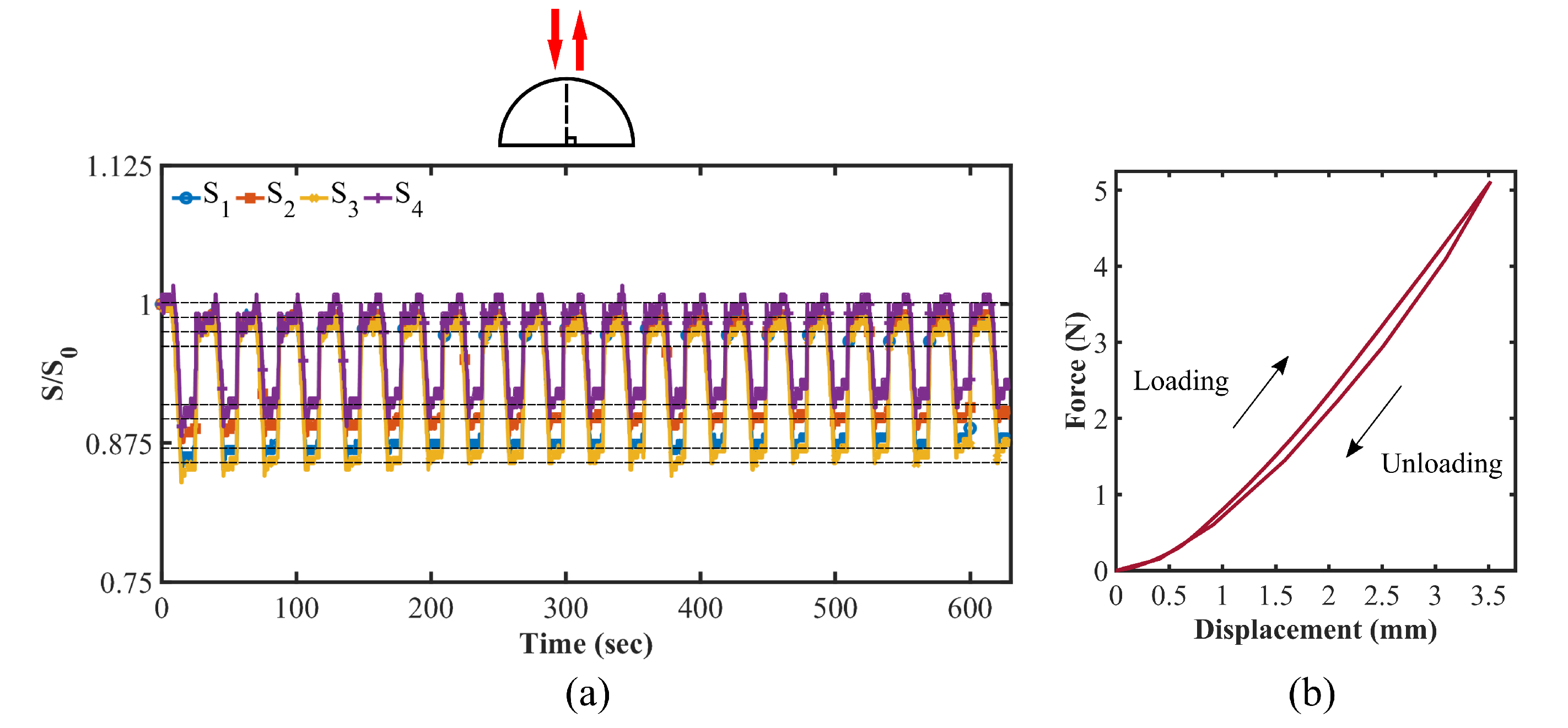
3.3. Cyclic Loading and Hysteresis Test

To investigate the preliminary stages of virtual hysteresis and data degradation from initial readings due to increased loading cycles, a cyclic loading experiment was performed in which a normal force up to 5 N was continuously applied to the silicone shell for 30-second increments. Offloading was performed instantaneously and the sensor was maintained in the resting position for a short time period before the next successive loading cycle. This process was manually repeated for a total of 20 cycles. The sensor output over the twenty cyclic loads is exhibited in Figure 14a with the corresponding force–displacement graph for one complete cycle of hysteresis testing shown in Figure 14b. Figure 14 reveals that the sensor structure is considerably resilient against hysteresis since the area within the hysteresis loop is quite small. The area under the curve of the loading cycle is found to be 7.35 × 10 3 J which corresponds to the strain energy required to generate the given stress in the material. The hysteresis loop area is estimated to be 0.55 × 10 3 J which indicates the amount of energy dissipated during one cycle. It is only 7.5% of the elastic energy stored during the loading cycle. Based on Figure 14, the flex sensors’ initial values do not deteriorate and can be regenerated even after a period of cyclic loading which ensures the repeatability of consistent output data for the given loading scenario.

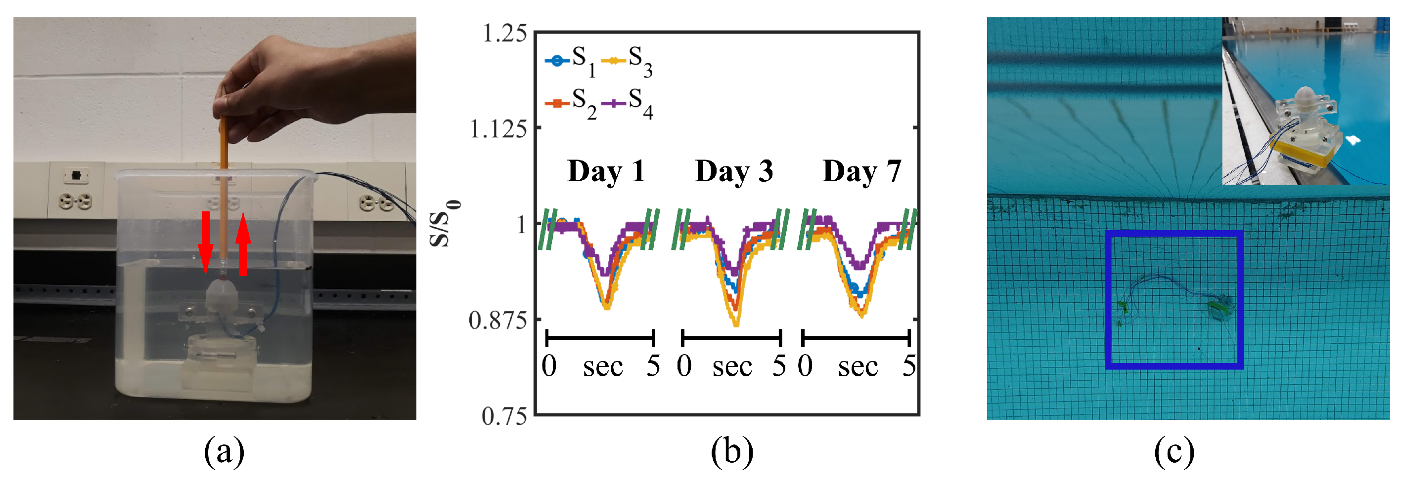
3.4. Waterproofing Test

Based on the sensor’s intended use underwater, it is critical to perform an underwater performance test. As a side-note to this study, a goal of the intended research is to integrate the fabricated sensor with a soft robotic gripper developed in a previous design study conducted in the same laboratory in order to fuse multi-directional force sensing with tactile shape sensing outfit for underwater applications. As a mention to the end-effector design, it is capable of tactile force and shape sensing outfit for potential use underwater [34]. Thus, following similar guidelines to the end-effector’s waterproofing test, the multi-directional force sensor presented in this study was submerged underwater (depth less than 0.5 m) for 7 days continuously while the electrical signals and connections of all four flex sensors were monitored for failure and ground-faults. Over the course of the 7 days a similar cyclic loading test was applied normal to the silicone shell. As a result to the study, all of the flex sensors maintained electronic integrity, whereas, the sensor remained mechanically intact and undamaged throughout the duration of the test. The representative image for the underwater test setup is demonstrated in Figure 15a. The time-dependent response of the sensor on day 1, day 3, and day 7 when subject to cyclic loading while submersed underwater is depicted in Figure 15b. Since the normal force loading cycles were exerted manually, there is a slight variation in applied force magnitude which is depicted by the plotted data. However, it is to be noted that the initial values of all four flex sensors were preserved even after the sensor was submerged underwater for seven days. Thus, there does not seem to be any effect of hysteresis added by a 7-day water submersion test. These results indicate that the sensor’s functionality will not deteriorate under shallow depths throughout a seven-day submersion period. In order to further investigate the waterproofing capability of the sensor, it was placed at a 13 ft (∼4 m) depth in a swimming pool for an hour and tested immediately after being lifted from the pool. The sensor continued to work with no reduction in performance after being submerged at the depth for one hour. Representative images of that test have been demonstrated in Figure 15c. Two videos are provided in the Supplementary Materials of this report; one displaying the waterproofing test in real-time, and the other showing the sensor performance after being removed from the pool. The videos certify the fact that the sensor is waterproofed for continuous submersion and robust enough to protect its electrical connections from water intrusion even under 4 m deep water.
According to the International Standard (ISO 20653), the IP68 standard means that the tested object is dust-tight and can withstand continuous submersion (half an hour) in water (depth 1.5 m) without risk of harmful water intrusion that would impair the performance of the object [35,36,37]. Based upon the proven data set presented in this report, the sensor can be entitled to qualify for achieving the IP68 standard in terms of waterproofing. This is a significant improvement from the previous implementation of the multi-directional force sensor which could only achieve an IP67 level of protection against water [30]. The successful waterproofing test insinuates the sensor’s prospects for underwater exploitation.

4. Conclusions

In summary, a viable conceptual design framework was demonstrated to fabricate a fully waterproof multi-directional force sensor. Fabrication methodology, characterization procedures, and results were provided to visualize the sensor’s conceptualization and performance. As depicted by calibration and data analysis, the sensor is capable of producing repeatable data patterns to characterize trends in normal force, off-axis force, and shearing force. The maximum amount of force the sensor can accurately detect is found to be up to 4 N. A numerical simulation was also conducted on the soft silicone shell of the sensor to characterize deformation when subject to normal and off-axis forces, whereas a dimensionally accurate and simplified model of the sensor was used to conduct the simulation. The outcome of this design study highlights a significant improvement to the previous version of the multi-directional force sensor formerly reported in [30], while the previous rendition of the sensor was rated to IP67 standards, this sensor achieved an IP68 rating meaning that the tested object is dust-tight and can continuously be submerged without water causing harmful effects, while this sensor design is a proven step forward in multi-directional force sensing for underwater applications, it is also a successful implementation of low-cost components in an underwater tactile force detection system capable of delivering repeatable and consistent results. This is a tremendous step forward in regard to low-cost tactile force sensing solutions, though there are some limitations due to the stage of design development and testing. General force vector generation in 3D space is yet to be achieved before the sensor can be adapted to industry-grade applications. Waterproofing tests at depths greater than 4 m are also required to investigate the sensor’s extended performance at deeper depths. Furthermore, the compact size of the sensor is ultimately limited by the dimensions of off-the-shelf flex sensors used for sensing elements. Though, custom micro-fabricated flex sensors could ultimately reduce the package size of the technology. A complete list of materials and a fabrication section are provided so that the sensor can be re-created, such that the concept can be iterated upon and inspire more advanced implementations of piezo-resistive multi-directional force detection methods. In closing, this design study widens the scope of proven tactile force-sensing technologies for underwater applications by placing special emphasis on soft robotics and multi-directional force detection.

Supplementary Materials

The following supporting information can be downloaded at: https://www.mdpi.com/article/10.3390/applmech3030042/s1, Video S1: Real time Sensor output Underwater; Video S2: Sensor output after being lifted off 4m deep swimming pool.

Author Contributions

Conceptualization, R.A.S.I.S., L.B.C. and K.P.; fabrication, L.B.C. and R.A.S.I.S.; visualization, L.B.C. and M.M.H.S.; data collection, R.A.S.I.S.; data analysis, R.A.S.I.S. and M.M.H.S.; investigation, R.A.S.I.S., M.M.H.S. and L.B.C.; resources, K.P.; writing—original draft preparation, L.B.C., R.A.S.I.S. and M.M.H.S.; writing—review and editing, L.B.C., R.A.S.I.S., M.M.H.S. and K.P.; supervision, K.P.; project administration, K.P.; funding acquisition, K.P. All authors have read and agreed to the published version of the manuscript.

Funding

This research work is supported by UMass Dartmouth’s Marine and Undersea Technology (MUST) Research Program funded by the Office of Naval Research (ONR) under Grant No. N00014-20-1-2170.

Institutional Review Board Statement

Not applicable.

Informed Consent Statement

Not applicable.

Data Availability Statement

All the data are available upon request.

Acknowledgments

The authors of this paper would like to acknowledge the Department of Mechanical Engineering and the Department of Bioengineering at University of Massachusetts Dartmouth for providing the lab facilities to carry out the experiments and Dapeng Li for his guidance to calibrate the sensor using Shimadzu AGS-X Tester.

Conflicts of Interest

The authors declare no conflict of interest.

References

  1. Beccai, L.; Lucarotti, C.; Totaro, M.; Taghavi, M. Soft robotics mechanosensing. In Soft Robotics: Trends, Applications and Challenges; Springer: Berlin/Heidelberg, Germany, 2017; pp. 11–21. [Google Scholar]
  2. Kim, S.; Laschi, C.; Trimmer, B. Soft robotics: A bioinspired evolution in robotics. Trends Biotechnol. 2013, 31, 287–294. [Google Scholar] [CrossRef] [PubMed]
  3. Whitesides, G.M. Soft robotics. Angew. Chem. Int. Ed. 2018, 57, 4258–4273. [Google Scholar] [CrossRef] [PubMed]
  4. Shintake, J.; Cacucciolo, V.; Floreano, D.; Shea, H. Soft robotic grippers. Adv. Mater. 2018, 30, 1707035. [Google Scholar] [CrossRef] [PubMed] [Green Version]
  5. Pfeifer, R.; Lungarella, M.; Iida, F. The challenges ahead for bio-inspired’soft’robotics. Commun. ACM 2012, 55, 76–87. [Google Scholar] [CrossRef]
  6. Laschi, C.; Rossiter, J.; Iida, F.; Cianchetti, M.; Margheri, L. Soft Robotics: Trends, Applications and Challenges; Springer: Berlin/Heidelberg, Germany, 2017. [Google Scholar]
  7. Subad, R.A.S.I.; Cross, L.B.; Park, K. Soft Robotic Hands and Tactile Sensors for Underwater Robotics. Appl. Mech. 2021, 2, 356–382. [Google Scholar] [CrossRef]
  8. Marani, G.; Choi, S.K.; Yuh, J. Underwater autonomous manipulation for intervention missions AUVs. Ocean. Eng. 2009, 36, 15–23. [Google Scholar] [CrossRef]
  9. Yoerger, D.R.; Bradley, A.M.; Jakuba, M.; German, C.R.; Shank, T.; Tivey, M. Autonomous and remotely operated vehicle technology for hydrothermal vent discovery, exploration, and sampling. Oceanography 2007, 20, 152–161. [Google Scholar] [CrossRef] [Green Version]
  10. Kalwa, J.; Pascoal, A.; Ridao, P.; Birk, A.; Eichhorn, M.; Brignone, L.; Caccia, M.; Alves, J.; Santos, R. The European R&D-Project MORPH: Marine robotic systems of self-organizing, logically linked physical nodes. IFAC Proc. Vol. 2012, 45, 226–231. [Google Scholar]
  11. Lee, H.K.; Chung, J.; Chang, S.I.; Yoon, E. Normal and shear force measurement using a flexible polymer tactile sensor with embedded multiple capacitors. J. Microelectromechanical Syst. 2008, 17, 934–942. [Google Scholar]
  12. Huang, Y.; Yuan, H.; Kan, W.; Guo, X.; Liu, C.; Liu, P. A flexible three-axial capacitive tactile sensor with multilayered dielectric for artificial skin applications. Microsyst. Technol. 2017, 23, 1847–1852. [Google Scholar] [CrossRef]
  13. Zhang, H.; Wang, M.Y. Multi-axis soft sensors based on dielectric elastomer. Soft Robot. 2016, 3, 3–12. [Google Scholar] [CrossRef]
  14. Guo, Y.; Gao, S.; Yue, W.; Zhang, C.; Li, Y. Anodized aluminum oxide-assisted low-cost flexible capacitive pressure sensors based on double-sided nanopillars by a facile fabrication method. ACS Appl. Mater. Interfaces 2019, 11, 48594–48603. [Google Scholar] [CrossRef] [PubMed]
  15. Yu, P.; Liu, W.; Gu, C.; Cheng, X.; Fu, X. Flexible piezoelectric tactile sensor array for dynamic three-axis force measurement. Sensors 2016, 16, 819. [Google Scholar] [CrossRef] [PubMed] [Green Version]
  16. Wolterink, G.; Sanders, R.; van Beijnum, B.J.; Veltink, P.; Krijnen, G. A 3D-Printed Soft Fingertip Sensor for Providing Information about Normal and Shear Components of Interaction Forces. Sensors 2021, 21, 4271. [Google Scholar] [CrossRef] [PubMed]
  17. Harada, S.; Kanao, K.; Yamamoto, Y.; Arie, T.; Akita, S.; Takei, K. Fully printed flexible fingerprint-like three-axis tactile and slip force and temperature sensors for artificial skin. ACS Nano 2014, 8, 12851–12857. [Google Scholar] [CrossRef]
  18. Teshigawara, S.; Tsutsumi, T.; Shimizu, S.; Suzuki, Y.; Ming, A.; Ishikawa, M.; Shimojo, M. Highly sensitive sensor for detection of initial slip and its application in a multi-fingered robot hand. In Proceedings of the 2011 IEEE International Conference on Robotics and Automation, Shanghai, China, 9–13 May 2011; pp. 1097–1102. [Google Scholar]
  19. Viry, L.; Levi, A.; Totaro, M.; Mondini, A.; Mattoli, V.; Mazzolai, B.; Beccai, L. Flexible three-axial force sensor for soft and highly sensitive artificial touch. Adv. Mater. 2014, 26, 2659–2664. [Google Scholar] [CrossRef] [Green Version]
  20. Alfadhel, A.; Khan, M.A.; de Freitas, S.C.; Kosel, J. Magnetic tactile sensor for braille reading. IEEE Sensors J. 2016, 16, 8700–8705. [Google Scholar] [CrossRef] [Green Version]
  21. Yuan, W.; Dong, S.; Adelson, E.H. Gelsight: High-resolution robot tactile sensors for estimating geometry and force. Sensors 2017, 17, 2762. [Google Scholar] [CrossRef] [Green Version]
  22. Palli, G.; Moriello, L.; Scarcia, U.; Melchiorri, C. An intrinsic tactile sensor for underwater robotics. IFAC Proc. Vol. 2014, 47, 3364–3369. [Google Scholar] [CrossRef] [Green Version]
  23. Templeman, J.O.; Sheil, B.B.; Sun, T. Multi-axis force sensors: A state-of-the-art review. Sens. Actuators Phys. 2020, 304, 111772. [Google Scholar] [CrossRef]
  24. Liu, Y.; Bao, R.; Tao, J.; Li, J.; Dong, M.; Pan, C. Recent progress in tactile sensors and their applications in intelligent systems. Sci. Bull. 2020, 65, 70–88. [Google Scholar] [CrossRef] [Green Version]
  25. Muscolo, G.G.; Cannata, G. A novel tactile sensor for underwater applications: Limits and perspectives. In Proceedings of the OCEANS 2015-Genova, Genova, Italy, 18–21 May 2015; pp. 1–7. [Google Scholar]
  26. O’brien, D.; Lane, D. Force and explicit slip sensing for the AMADEUS underwater gripper. Int. J. Syst. Sci. 1998, 29, 471–483. [Google Scholar] [CrossRef]
  27. Aiguo, S.; Liyue, F. Multi-dimensional force sensor for haptic interaction: A review. Virtual Real. Intell. Hardw. 2019, 1, 121–135. [Google Scholar]
  28. Kappassov, Z.; Corrales, J.A.; Perdereau, V. Tactile sensing in dexterous robot hands. Robot. Auton. Syst. 2015, 74, 195–220. [Google Scholar] [CrossRef] [Green Version]
  29. Schafer, R.W. What is a Savitzky-Golay filter? [lecture notes]. IEEE Signal Process. Mag. 2011, 28, 111–117. [Google Scholar] [CrossRef]
  30. Subad, R.A.S.I.; Saikot, M.M.H.; Park, K. Soft Multi-Directional Force Sensor for Underwater Robotic Application. Sensors 2022, 22, 3850. [Google Scholar] [CrossRef] [PubMed]
  31. Dragon Skin FX-Pro. Available online: https://www.smooth-on.com/tb/files/DRAGON_SKIN_FX_PRO_TB.pdf (accessed on 24 March 2022).
  32. Slacker. Available online: https://www.smooth-on.com/products/slacker/ (accessed on 24 March 2022).
  33. ANSYS Mechanical APDL Theory Reference; ANSYS Inc.: Canonsburg, PA, USA, 2013; Chapter 15pp. 761–762.
  34. Cross, L.; Subad, R.; Park, K. Multi-modal Sensing Soft End-Effector for Underwater Applications. Adv. Robot. Mech. Eng. 2022, 3, 377–389. [Google Scholar]
  35. Zhou, Y.; Cong, L.; Peng, L.; Zhou, Y.; Zhang, Y.; Yun, X. System and method of drip test device for testing waterproof performance of large equipment. In Proceedings of the IOP Conference Series: Earth and Environmental Science, Jakarta, Indonesia, 25–26 September 2021; Volume 631, p. 012025. [Google Scholar]
  36. Zhaoming, L.; Jiabin, Z.; Jingling, Q. Road vehicles - protection level (IP code)—Protection of electrical equipment against foreign objects, water and contact. Environ. Technol. 2008, 29, 40–47. [Google Scholar]
  37. Łukjanow, S.; Zieliński, W. A concept of the assessment of Electric Vehicles’ Operational Safety (EVOS). In Proceedings of the IOP Conference Series: Materials Science and Engineering, Krakow, Poland, 22–23 September 2016; 2016; Volume 148, p. 012058. [Google Scholar]
Figure 1. Views of a 3D model of the soft multi-directional force sensor: (a) Side, (b) front, (c) isometric-1, and (d) isometric-2.
Applmech 03 00042 g001
Figure 2. Projected and cross-sectional dimensions of the soft multi-directional force sensor; linear dimensions: mm, angular dimension: degrees.
Applmech 03 00042 g002
Figure 3. Sensor exploded view and labeled components.
Applmech 03 00042 g003
Figure 4. Representation of normal and shear force phenomena: (a) original position with no contact force, (b) deformed position with normal force, and (c) deformed position with shear force.
Applmech 03 00042 g004
Figure 5. Sensor fabrication process; numbered photos correspond to the listed fabrication steps.
Applmech 03 00042 g005
Figure 6. Calibration test setup for the multi-directional force sensor: (a) force along with 0 inclination to the vertical axis; force exerted from the different directions along with (b) 30 and (c) 60 inclination to the vertical axis.
Applmech 03 00042 g006
Figure 7. Force calibration against the normal force on the top of the hemispherical sensor; top view of the sensor system is illustrated and the red dot represents the applied (vertical) force direction into the page.
Applmech 03 00042 g007
Figure 8. Readouts of the sensor for applied forces along 30 with vertical axis, on the sides of the hemispherical sensor at 30 latitude (exactly on the (a) S 4 , (b) S 1 , (c) S 2 , and (d) S 3 flex sensors); top view of the sensor array is demonstrated and the red arrow depicts the applied force direction.
Applmech 03 00042 g008
Figure 9. Force calibration against forces along 60 with vertical axis of the sensor, on the sides of the hemispherical sensor at 30 latitude (specifically on the (a) S 4 , (b) S 1 , (c) S 2 , and (d) S 3 flex sensors); top view of the sensor array is illustrated and the red arrow depicts the applied force direction.
Applmech 03 00042 g009
Figure 10. Readouts of the sensor against forces along 30 with vertical on the sides of the hemispherical sensor at 30 latitude (in between inserted two consecutive (a) S 4 and S 1 , (b) S 1 and S 2 , (c) S 2 and S 3 , and (d) S 3 and S 4 flex sensors); top view of the sensor system is shown and the red arrow illustrates the applied force direction.
Applmech 03 00042 g010
Figure 11. Force calibration against forces along 60 with vertical on the sides of the hemispherical sensor at 30 latitude (in between inserted two consecutive (a) S 4 and S 1 , (b) S 1 and S 2 , (c) S 2 and S 3 , and (d) S 3 and S 4 flex sensors); top view of the sensor system is exhibited and the red arrow shows the applied force direction.
Applmech 03 00042 g011
Figure 12. Steps to simulate the sensor shell deformation: (a) (i) geometry of the sensor and (ii) unstructured mesh, (b) direction and location of the applied forces: force parallel to (i) vertical or y-axis at 90 latitude and (ii) 60 to the vertical at 30 latitude, and (c) contour of total deformation as the result of force applied (i) vertically and (ii) along 60 as shown in the previous step (b).
Applmech 03 00042 g012
Figure 13. Deformation of the sensor for the applied forces (a) At 90 latitude and (b) At 30 latitude on one of the flex sensors.
Applmech 03 00042 g013
Figure 14. Cyclic loading test results; (a) sensor readouts for cyclic loading, (b) corresponding force-displacement hysteresis loop for one loading-unloading cycle; side view of the sensor is presented, red arrows representing the exerted and retracted cyclic force directions along vertical axis; dashed lines are used for referencing the individual flex sensor output.
Applmech 03 00042 g014
Figure 15. Waterproofing test for the sensor: (a) exerting and retracting vertical force (depicted by the red arrows) underwater, (b) corresponding reading changes of the sensor, and (c) sensor being submerged at 13 ft (∼4 m) depth (inset image shows the sensor being held by a custom made fixture).
Applmech 03 00042 g015
Table 1. Sensor components and materials.
Item No.DescriptionMaterial
1Outer ShellDragon Skin FX-Pro Platinum Cure Silicone, Slacker Silicone Tactile Mutator
2Flex Sensor, modified to 17 mm lengthAdafruit Short Flex Sensor, Crimp-on Wire Connector
3Solid-core WireBlue, 30 AWG, PTFE Wire Jacket
4Inner ShellDragon Skin FX-Pro Platinum Cure Silicone, Slacker Silicone Tactile Mutator
5Internal Sensor Retaining RingFormLabs V4 Clear Resin
6External Sensor Retaining RingFormlabs V4 Clear Resin
7Button Head Cap Screw with O-ring, M3.5 × 0.6, 12.5 mm Long316 Stainless Steel, Bun-N Rubber, Rockwell B96
8Mineral OilISO Grade 32, McMaster-Carr 1849K11
9DEVCON 2 Part EpoxyStructural Adhesive for Plastic, McMaster-Carr 7541A76
10Sil-Poxy AdhesiveSilicone Rubber Adhesive
Publisher’s Note: MDPI stays neutral with regard to jurisdictional claims in published maps and institutional affiliations.

