1. Introduction
A moveable joint will often contain minimum two counterparts that turn relative to each other, ideally around a center line in common. The joint can have a female part, a fork, and a male part, together with typically a bearing. Moveable joints are in use in uncountable numbers of different applications, in most industries globally and many different machines and mechanical equipment [
1]. In addition, bearings are used in static joints in civil engineering and constructions. By applying a moveable joint, it is possible to transfer heavy loads of any equipment from one position to another or turn rotational movements into axial directional movements [
2]. The moveable joints in general can be found in many well-known and familiar tools and furniture, like scissors, garden shears, and rotating chairs, as well as in more industrialized tools, equipment, and machines. Efficient, safe, and well-working moveable joints are indispensable in most industrial equipment and machines such as offshore and onshore cranes, drilling and pipe handling equipment, excavators, dumper trucks and other vehicles for earth moving, windmill systems, flood control gate ports, and even launch platforms for spaceships and rockets. [
3]. In addition to the two counterparts that turn relative to each other [
4], a third component is required to make a joint moveable, which could be a pin connection with female and male parts as shown in
Figure 1a,b. The pin in a moveable joint can be of many different designs, with different advantages or disadvantages. In general, it is an advantage to have as tight tolerance as possible between the pin and the female part (supports), and against the male part during operation of the machine, to avoid any unwanted movements of a cylindrical pin (
Figure 1c), which can result in mechanical wear and increased play. At the same time, it is an advantage to have wider tolerances [
5] during installation and retrieval of the pin, to avoid the pin getting stuck in the supports. The different pin designs value differently the tightness of the tolerance, either very tight to increase the quality of the joint during operation, or less tight to ease installation and retrieval of pins. It is common to lubricate the pin and the bore inner surface to reduce friction between surfaces in contact for installation and retrieval purposes [
5] and to protect against oxidation, but it is not always required. Such lubrication is typically made of petroleum hydrocarbon distillate with additives to get the specific and required properties.
The aim of the study reported in this paper is to investigate the effects and consequences of locking an expanding bondura® Dual Pin (Bondura Technology AS, Bryne, Norway) to the inner ring of a Radial Spherical Plain Bearing (RSPB) and compare that with the use of a standard cylindrical pin, for both dry and lubricated contact surfaces. As part of the experimental work, the bearing inner ring is separated from the outer ring and loaded separately with a pressure load acting radially outwards, and its deformations are measured by a Coordinate-Measuring Machine (CMM) to find the relationship between the radial load and the corresponding ring deformation. In addition, the complete bearing with lubricated internal surfaces was installed on a Dual pin and then loaded stepwise with combinations of radial outward force from the expanding sleeve and external inwards radial load representing operational loads. The assembly was then forced to turn, and the required static moment at the exact moment of turning was observed.
2. Literature Review
Traditionally, mechanical joints for load transfer are designed with interference fitting such as shrink fitting and press fitting or using standard cylindrical pins, while expanding pin solutions are more innovative solutions with wide installation tolerances.
Shrink fitting [
6] is a method to shrink a slightly oversized pin, by cooling it down with frozen nitrogen, and introduce it into the joint and let it expand back to its normal temperature, at which the interference fit is produced with the contacting support bore surfaces. This solution has a wider installation tolerance and zero operational tolerance between the surfaces in contact. Shrink fitting as a method for joining two mechanical parts has been investigated over many years, e.g., McMillan et al. [
7] studied the slip between a hub and a shaft in a shrink-fit assembly subjected to axial load, and Mouaa et al. [
8] reported an analytical methodology to analyze the elastic-plastic stresses in a shrink fit with a solid shaft.
Press fitting is another method of interference fitting where a slightly oversized pin is assembled into the female part by applying an axial external load. In this method, the pin is forced into correct position in the joint, reaching the interference fit with the contacting surfaces. This solution has negative/zero installation tolerance and zero operational tolerance, and the performance of this method has been studied both numerically, analytically, and experimentally over the years [
9,
10].
The most common solution is using a standard cylindrical pin joint, where a massive cylindrical dowel pin with a wide enough installation tolerance is used to install the pin without interference. This solution has a wider installation tolerance, which also is the operational tolerance and is often provided with a locking plate installed to prevent the pin from falling out over time.
The expanding pin solution [
11,
12] is less known but combines the wide installation tolerance from the standard pin solution, and often even wider, with the zero operational tolerance from the shrink fit and press fit solutions. There is a variety of different expanding pin solutions depending on the issues to be addressed, where most of them can expand to zero operational tolerance against the supports. The dual pin solution [
11], however, expands in addition against the bearing, to a zero operational tolerance. The operational and damage mechanisms and the advantages of this solution are not sufficiently addressed in the literature. In the recent works of the authors, however, some research results have been reported. For instance, the expanding pin solution, as a part of a mechanical joint, has been compared to other known joint models and modelling techniques, by Karlsen and Lemu [
13,
14], with focus on the damage mechanisms that can occur in various connections of mechanical systems, typically such as fretting wear, fretting corrosion, and fretting fatigue. In addition, Akhtar et al. [
15] reported a study on the capacities of a pin with the combination of radially expanding and axially pre-load capabilities, typically for huge flange systems. Berkani et al. [
16] performed an experimental and numerical study of expanding pins with the aim of knowing more about the relation between the tightening torque and stresses generated at the contact surfaces, in addition to the effects of variations in temperature over time.
Öztürk et al. [
17] performed an experimental test to determine the coefficient of static friction (COFs) for RSPBs, for polyoxymethylene (POM)/steel contact surfaces. The bearing was exposed to increasing external radial inwards directed load, and the bearing inner ring was turned relative to the outer ring and the COFs values calculated. They concluded that whereas the static friction force increased with increasing normal force, the coefficient of static friction decreased until it stabilized. Zhao et al. [
18] investigated failure behaviors of RSPB joints for use in civil engineering applications, and the main findings were brittle fracture of the inner ring and brittle crack of the outer ring under uniaxial radial load, when the pin shaft bent due to overload. Under such loading conditions, the inner ring would have pressure from the outer ring at a limited width around its center line, due to difference in outer ring inner diameter and inner ring outer diameter, but reduced or missing support from the pin shaft around the same center line, due to the bending of the pin. This will result in bending of the inner ring and additional stresses and finally brittle fracture of the edges. Sun et al. [
19] studied the use of RSPBs in joints in a space truss structure, subjected to tension and compression, to verify the bearing’s mechanical properties and reliability. Fang et al. [
20] developed a theoretical solution and a numerical model for conformal contact pressure and free-edge effects in spherical plain bearings, which varies with the bearing clearance and external load.
In the global market, only a few companies produce expanding pin solutions, and to the authors’ knowledge, only one company produces the double sets of expanding sleeves, called Dual pins, for locking a second set of expanding sleeves to the bearing. The stakeholders’ opinions, experiences, and the use of expanding pins on the global arena have been investigated by Karlsen and Lemu [
21,
22].
2.1. Expanding Pins
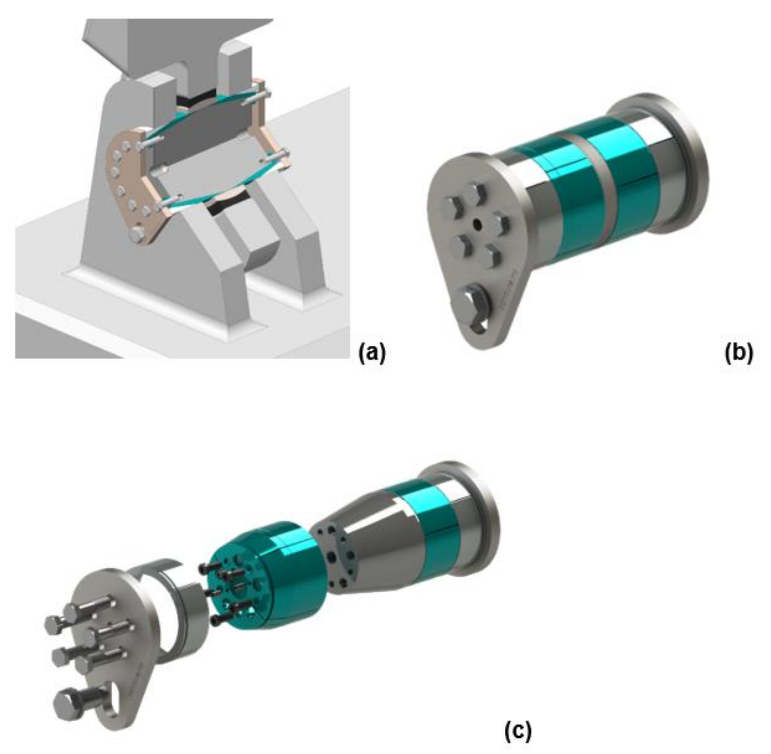
A typical expanding pin assembly, illustrated in
Figure 2, has (1) a load bearing pin with conically machined tapered ends, (2) conically machined end-sleeves to fit the tapered pin ends, and (3) end plates and tightening screws or nuts. In addition, the assembly can have lubrication channels, if required. When torquing the screws or nuts, the end-sleeve climbs on the tapered pin end and expands until reaching a zero tolerance between the sleeve and the support bore and produces then a wedge force. The contact pressure between the support bore and the sleeve, and between the sleeve and the pin, prevents the pin assembly from rotating or displace axially and thereby prevents any unwanted surface wear, ovality issues, etc. The Dual expanding pin can produce a similar wedge lock against the bearing inner ring by a second inner set of expanding sleeves.
2.2. Dual Expanding Pins
The Dual expanding pin solutions, illustrated in
Figure 3, are applied in various types of industrial cranes offshore or onshore, ports, drilling and pipe handling equipment, rotating sheaves, amusement equipment, A-frames (
Figure 3a), hatches on ships, flood dike gates, etc., and the pins often interact with bearings [
11]. In such applications, the bearings can typically be of spherical plain or rolling type of bearings, with the latter divided into ball bearings and roller bearings. The inner sleeve expands towards the inner ring of the bearing but creates normally less contact pressure compared to what the outer sleeve does against the support bore. The contact pressure between the bearing and the expanding sleeve is enough to prevent the bearing inner ring from rotating but not high enough to disturb the bearing’s function by expanding the inner ring and eliminate the bearing’s radial inner production tolerance.
Figure 3b illustrates a dual pin assembly, and
Figure 3c illustrates a dual pin where one half is shown with an exploded view.
4. Discussion of Results
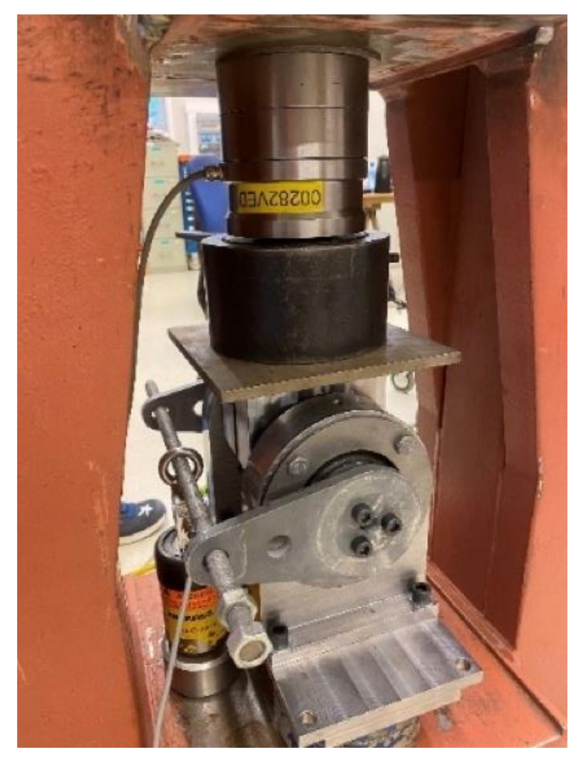
As shown in
Figure 4a, Test 1a comprises an internal, radially outwards directional loading of two separate SKF GE 80 ES bearing inner rings, together with the corresponding setup for diameter deformation measurement using a CMM. Each ring was mounted on separate single expanding sleeves as illustrated in
Figure 4a
Figure 6a.
Figure 8,
Figure 9,
Figure 10 and
Figure 11, from Test 1a and Test 1b, represent how the RSPB inner rings deform with increasing tightening screw torque. It is assumed that the effects from the expanding sleeves will give the same deformation pattern on the inner ring when they are installed in a bearing on an expanding pin, the radial clearance between the inner and outer rings is still not reduced to zero, and the bearing is not exposed to external loads.
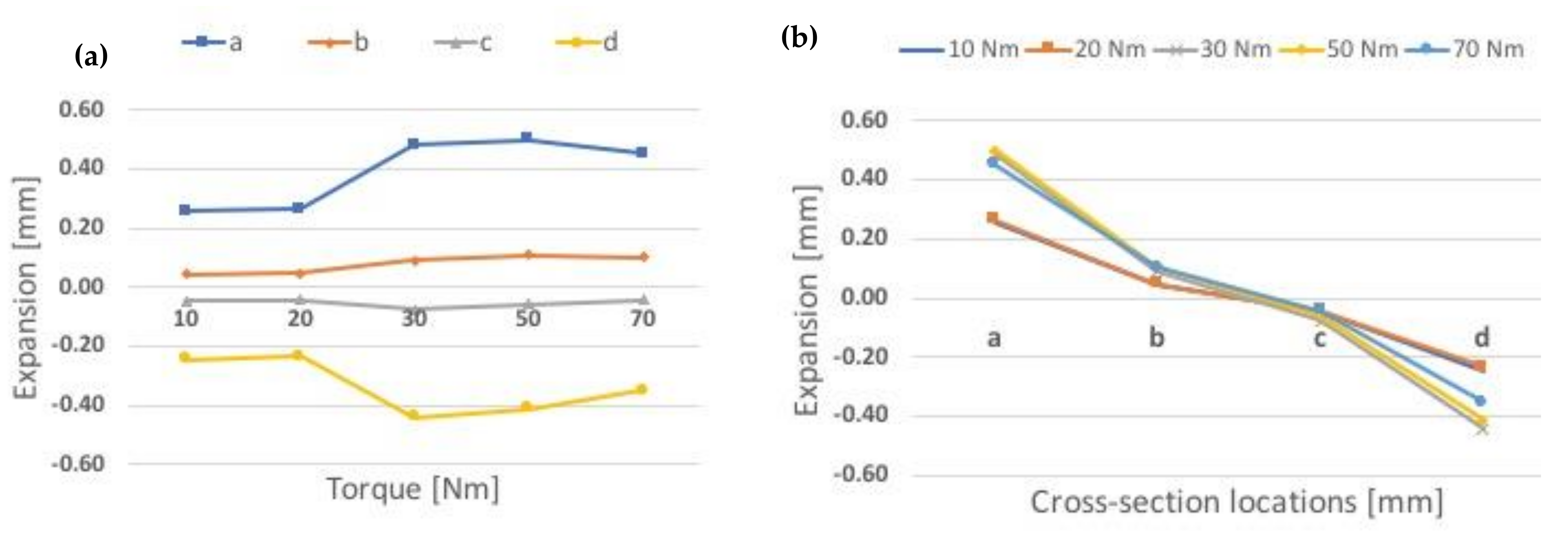
The deformations of the ring on a single sleeve (Test 1a), for dry and lubricated sleeves, can be seen by comparing the results shown in
Figure 8 and
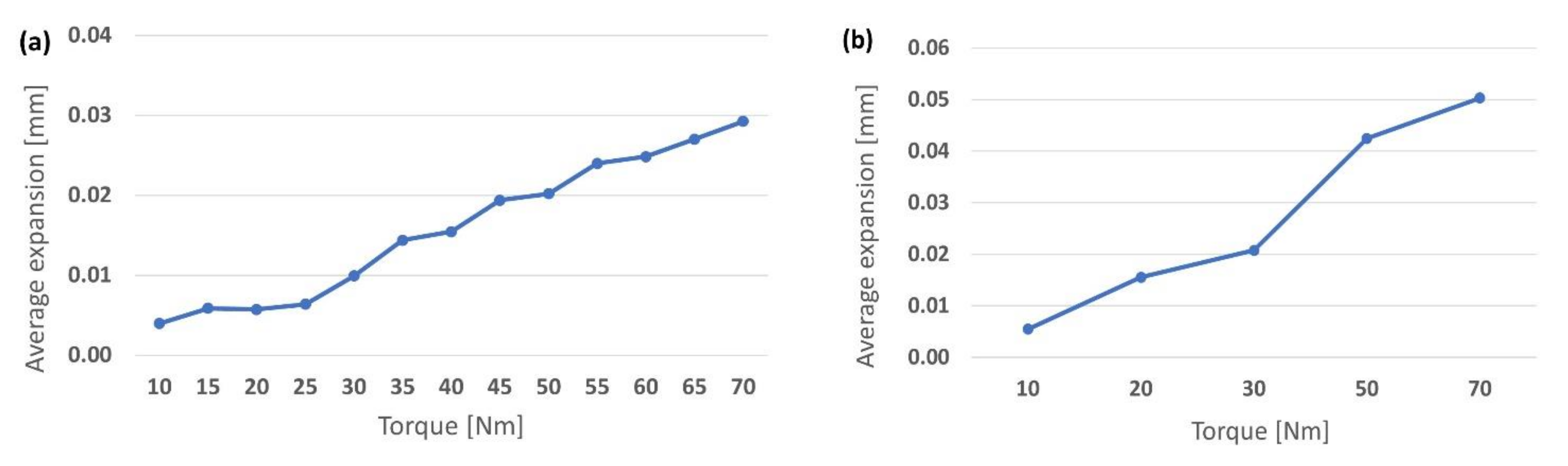
Figure 9. In the dry case, the ring expands up to 0.410 mm (90.5% of its maximum) at 25 Nm torque, and it stays relatively constant until its maximum of 0.453 mm was reached at 65 Nm torque, at section “a”, which is close to the ring end. At the opposite side of the ring, it contracts to slightly smaller values, or down to 90%. In the lubricated case (
Figure 9), the ring expansions and contractions have increased compared to the dry case. Maximum expansion at section location “a” is 0.499 mm at 50 Nm torque, and maximum contraction at same section is 0.442 mm, at 30 Nm torque.
The contraction at the sleeve exit side is almost equal to the expansion at the sleeve entrance side, which stays at or close to 0.40 mm (expansion 347–453 µm and contraction 327–404 µm) at the torque range from 25 Nm up to 70 Nm. The maximum expansion and contraction over the torque range increased slightly with lubricated sleeves but not more than 10%. The average expansion varies up to 3 times higher for the lubricated case compared to the dry case, in the torque range of 20–70 Nm, shown in
Figure 12 and
Figure 13. For Test 1a, the main expansions and contractions are seen at the ring end sections.
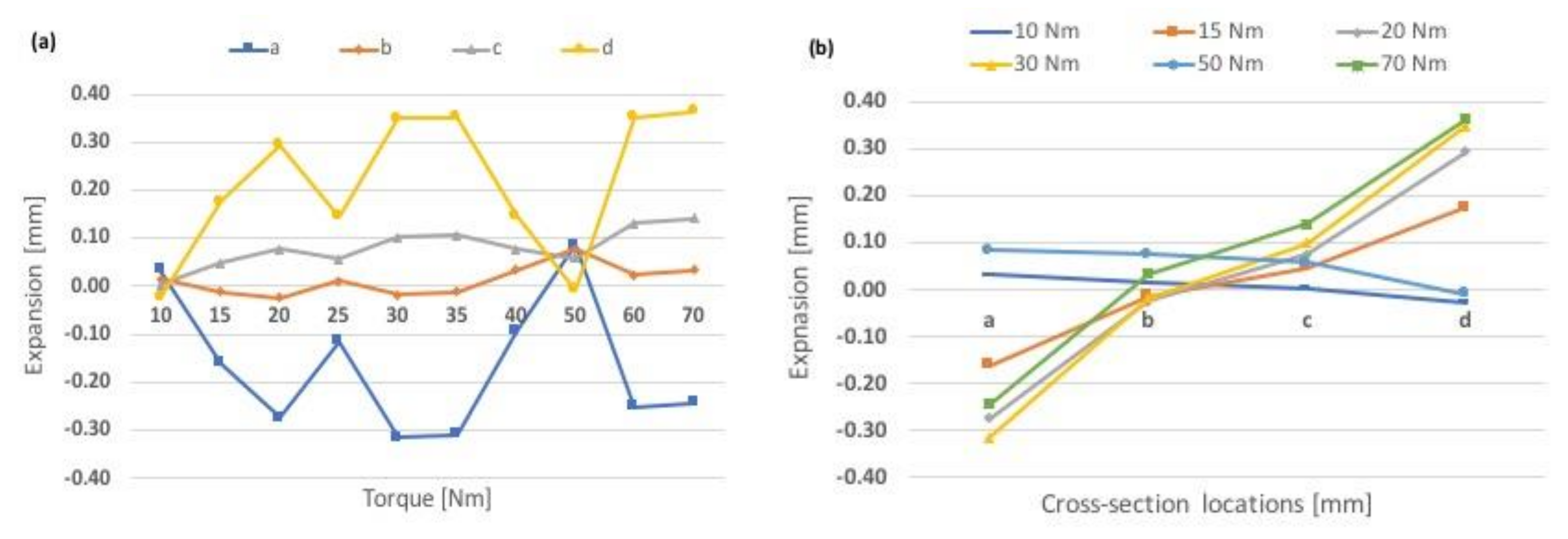
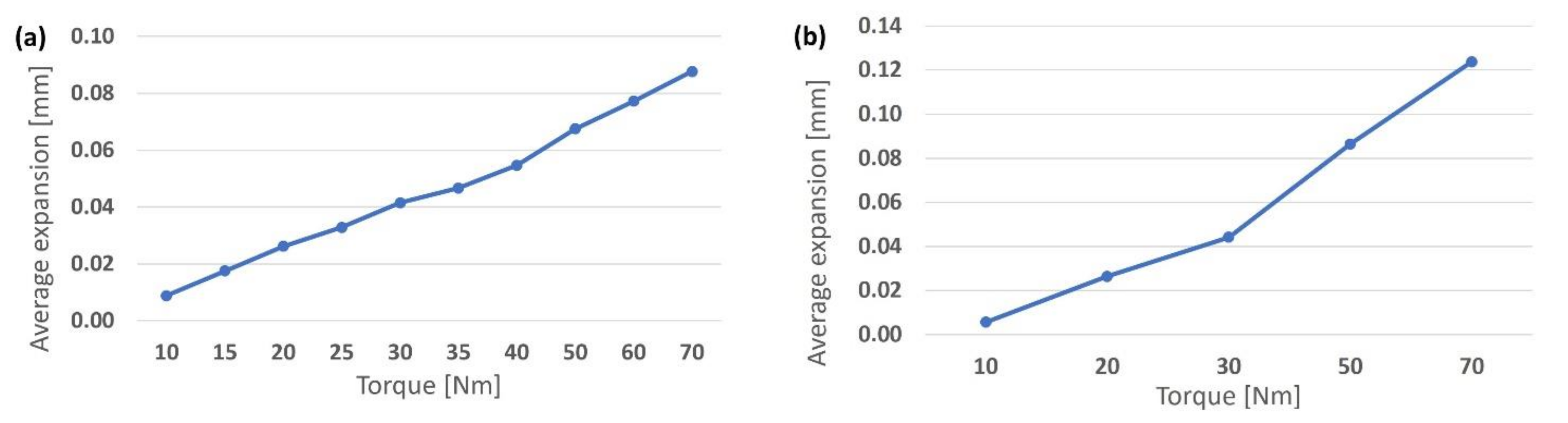
Test 1b was executed in a similar way as Test 1a, but the ring was supported on two separate expanding sleeves at the same time, entering at each ring end, so they leave an unsupported area at the mid part of the ring as illustrated in
Figure 4b and
Figure 6b. The differences between the deformations of the ring on a double sleeve (Test 1b), for dry and lubricated sleeves, can be seen by comparing the results shown in
Figure 10 and
Figure 11.
The non-lubricated case shows a serrated shaped curve where the expansion first increases and then decreases to “close to zero” when the accumulated/hysteresis surface contact stress is overcome, with increasing torque. When the ring expands by torquing the bolts and pushing the sleeves, the surface contact friction between ring and sleeve, as well as between sleeve and pin, increase and accumulate. When the torque is increased from 10 to 20 Nm, the expansion at section “d” increased from around 0 to around 0.30 mm (
Figure 10a) and decreased almost equally at the opposite ring end, at section “a”. The expansion of the sleeves changed the inner shape of the ring from perfectly cylindrical (within production tolerances) to slightly conical cylinder.
When the torque is increased further up to 25 Nm, the pushing force from the sleeves overcomes the accumulated surface contact stress; it is released, and sliding occurs, possibly between both contact surfaces (ring/sleeve and sleeve/pin) at the same time. When sliding occurs the ring tries to go back from the conical-cylindrical shape to the perfect cylindrical shape, and the contact stress gets more evenly distributed and consequently reduces the ring expansion down to “close to zero” at the “d” section and increases up to “close to zero” at the “a” section. As can be observed from
Figure 8a and
Figure 10a, the same serrated shaped curve pattern can be seen when increasing the torque from 0 to 70 Nm.
In the lubricated case, it can clearly be seen that the expansion is reduced for all tightening torques, except for the lowest, and it is practically unchanged over the torques range 30–70 Nm. The maximum expansion values for 30, 50, and 70 Nm in the lubricated case are 0.047, 0.087, and 0.124 mm, respectively, compared to the fabric new bearing clearance of 0.072–0.142 mm. As can be observed from the plots in
Figure 13, the average expansion varies up to 1.4 times higher for the lubricated case, in the torque range of 20–70 Nm. The lubricated case shows the highest asymmetry at the lowest torque, 10 kN, compared to the non-lubricated case where the asymmetry was around zero. The reason for this is assumed to be that in the lubricated case, the sleeves could move easier due to less friction resistance and thereby expand the ring at the sleeve entrance side that was torqued first (section “a”). When torquing the opposite side (section “d”), part of the asymmetry was eliminated, but not all, while for the non-lubricated case, the torque was lost into increased hysteresis surface contact stress and did not expand the ring until the torque was increased. When the torque increased, the accumulated or hysteresis surface contact stress was overcome, the sleeves slid, and the inner ring shape went back to its normal cylindrical shape or reduced its asymmetry as shown in
Figure 11a. The effect of increasing expansion on each side of the inner ring independent of each other, from two different expanding sleeves, forces the ring into a less asymmetric shape. For Test 1b the main expansions and contractions are seen at the ring center sections.
The ring diameter changes at the 4 ring cross-section locations with non-lubricated and lubricated sleeves can be seen in
Figure 10 and
Figure 11, respectively. The ring average expansion over the rings for Tests 1a and 1b are illustrated in
Figure 12 and
Figure 13.
The radial expansions for different inner ring cross-sections presented in
Figure 8,
Figure 9,
Figure 10 and
Figure 11 are represented by the deformation -
u- in formula (6), and the corresponding inner pressure
p1 and tangential hoop stress
σθ can be calculated, with the outer pressure
p2 = 0, whose results are given in
Table 2 and
Table 3.
Test 2a comprises of two complete RSPBs mounted each on one single sleeve on an expanding pin and loaded both internally (i.e., radially outwards directional loading from expanding the sleeves by torquing the tightening screws) and externally (i.e., radially inwards load from the hydraulic load machine), as shown in
Figure 5a and
Figure 7. The results from loading the bearing stepwise with internal and external loads and the measure of the required moment to turn the outer ring relatively to the locked inner ring of the bearing on single sleeve are shown in
Figure 14. The highest rotational moments are seen at both the lowest and highest tightening torque, 5 and 65 Nm, respectively, and they increase with the increasing external load, for all torque values. The lowest rotational moments occur at 25 and 45 Nm. The reasons for this behavior are understood to be:
- -
At the lowest torque value, the expansion of the inner ring is zero, as illustrated in
Figure 8a, as it would have been in a joint connection with a standard cylindrical pin installed. The required moment to turn the bearing is illustrated in
Figure 14a,b, and these values represent fabric new bearings, with a contact surface between the bearing rings that depends on the specific bearing ring tolerance, which is in the range of 72–142 µm. A wide ring tolerance results in a reduced contact area between the two bearing rings and increased contact stresses, with possible accelerated removal of lubrication at the contact areas, followed by increased rotation moment. An increase of the external load increases the turning moment, as the contact pressure between the rings increases.
- -
When the torque level is increased to 25 and 45 Nm, the inner ring expands with a slightly serrated shape as illustrated in
Figure 8a and changes the ring inner surface shape from cylindrical to conical-cylindrical, with increased opening diameter in one end and reduced opening at the other end. With increased external load, the ring shape is forced back to cylindrical shape, and the total average ring expansion can be seen in
Figure 12a. The expansion of the inner ring increases the contact area between the two bearing rings and reduces the contact pressure. These expansion values are below the fabrication tolerances of the bearing, and the required turning moment is reduced, compared to the lowest torque value.
- -
At the maximum torque value of 65 Nm, the average expansion increases to a level still lower than the bearing internal minimum tolerances (
Figure 12a), but the maximum expansion at the inner ring end is 0.45 mm (
Figure 8a) which is three times over the bearing maximum tolerance. It is possible that the external load cannot push the ring back from the conical-cylindrical to the original cylindrical shape, and with high contact pressure areas between the two rings, the results show high rotation moment for high torque as well as for low torque.
Test 2b is performed in a similar way as Test 2a but with one single bearing at the assembly mid part, expanded by two separate sleeves. For the double sleeve setup (Test 2b), the highest rotational moment was clearly only at the lowest tightening torque, 5 Nm, as illustrated in
Figure 15, and the remaining torque values in the range of 25–65 Nm did not give any major scattering in moment values. The rotational values are almost identical at torque value 55 Nm, for all external loads, with only a ±9% variation. At the maximum external load, 400 kN, the rotational moment reaches 1903 Nm with 5 Nm torque, and 266–466 Nm with torque values in the range of 15–65 Nm. The high rotational moment for the lowest torque is understood to come from the same reasons as for Test 2a. When the torque is increased to 30 Nm the asymmetry of the ring is reduced to almost zero, see
Figure 11. This can be observed because all sections of the ring have increased almost identically (in the range of 0.025–0.05 mm). When the torque further increases from 30 Nm to 70 Nm, the ring stays close to symmetric over its axial length, and the ring diameter increases with increasing torque. Due to the expanding sleeves coming into the ring from both sides, in combination with increasing external load, the ring is continuously forced back from any conical-cylindrical shape to cylindrical shape; the high contact pressure area between the two rings is avoided, and the high rotation moment does not occur for any increased torque value, within these tests.
A bearing mounted on an expanding pin will experience the inner ring expanding and the contact area between the inner and outer ring increasing with increasing internal load. As a result of external overload, the pin shaft could bend and then also the bearing inner ring, as described by Zhao et al. [
18]. Such bending of the pin shaft could lead to increased loss of contact area between pin and inner ring at the ring center, combined with high load from the outer ring at the inner ring center area. This can lead to bending of the inner ring and subsequently brittle crack initiation at the contact areas between inner ring and pin, and inner ring and outer ring.
5. Conclusions
The setup with one bearing on two combined expanding sleeves (designated as Test 2b) clearly shows that a low tightening torque of 5 Nm results in high required rotational moment, compared to higher torques. The 5 Nm torque curve represents a rotational moment close to 1900 Nm at 400 kN external load, and for all other torques at the same external load, the rotational moments are in the range of 266–466 Nm, which is a drop in rotational moment in the range of 75–86%. The measured rotational moments decrease substantially with only a small increase in tightening torque, due to increased inner ring expansion and reduced high contact pressure areas between the two rings, resulting in lower contact surface stresses between the two bearing rings, with improved lubrication effects. The inner ring expands when the torque levels are increased but not enough to eliminate the internal ring clearances. Thus, the ring contact pressure is reduced when the torque level is increased. For this bearing setup, it can be concluded that expanding the inner ring using expanding pin solutions will lower the total friction forces between the two rings for all external loads. The rotational moment is practically not increasing for each of the torque values within the range from 15 Nm to 65 Nm, within the higher external load range of 200–400 kN.
Following the results of this study, it is open to question whether a RSPB installed on a standard cylindrical pin shaft without the expanding effect will also suffer high friction between the rings and thereby a possibly reduced lifetime compared to the use of an expanding pin solution with a tightening torque above 5–10 Nm. The healthiest set up for the case with one bearing on two sleeves will be to apply a torque level of 20–30 Nm, which gives an equal distributed expansion of the inner ring and an expansion level within or at the lower level of the bearing inner clearance limits of 0.072–0.142 mm, where 20 Nm torque results in a 0.026 mm and 30 Nm in a 0.042 mm ring expansion with dry sleeves, and a 0.026 mm and a 0.044 mm ring expansion for lubricated sleeves, respectively.
The setup with one bearing on one single sleeve (designated as Test 2a) shows that both the lowest and highest torques, 5 Nm and 65 Nm, respectively, result in higher and almost identical rotational moments in the external load range of 200–400 kN. The reason for the high moment at low torque would be the same as in Test 2b, and the high moment at high torque is understood to come from the ring deformation shape, as shown in Test 1a. One side of the inner ring expands and encounters the outer ring and is not pushed back to its cylindrical shape, and high surface contact pressure areas are produced which increase the rotational moment. The healthiest set up for the bearing in this case seems to be with a tightening torque regime in the range of 25–45 Nm with dry sleeves with 0.006 mm and 0.019 mm ring expansion, or 20–40 Nm with lubricated sleeves, and with 0.016 mm and 0.032 mm ring expansion. When lubricating the sleeves, a higher part of the energy input (torque) goes to expand the bearing inner ring, and less is lost in overcoming friction.
Based on this study and its findings, further investigations can be recommended, especially with the use of finite element analysis (FEA) where a wider diameter range of expanding pins can be analyzed, in addition to standard cylindrical pins, in combination with extended laboratory testing. The variables of interest are diameter, bearing type, friction, torque, and external load. In addition, it could be of interest to run bearing fatigue tests with expanding pins.


