
Design Analysis of Prosthetic Unilateral Transtibial Lower Limb with Gait Coordination


Abstract
:1. Introduction
2. Methodology
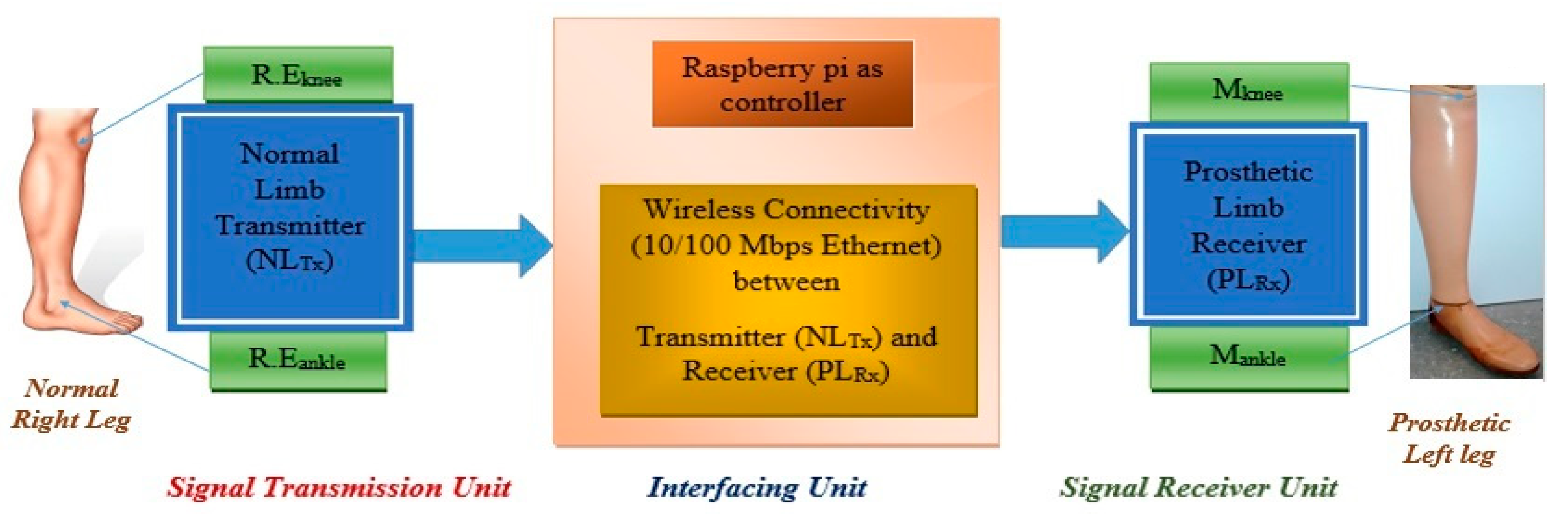
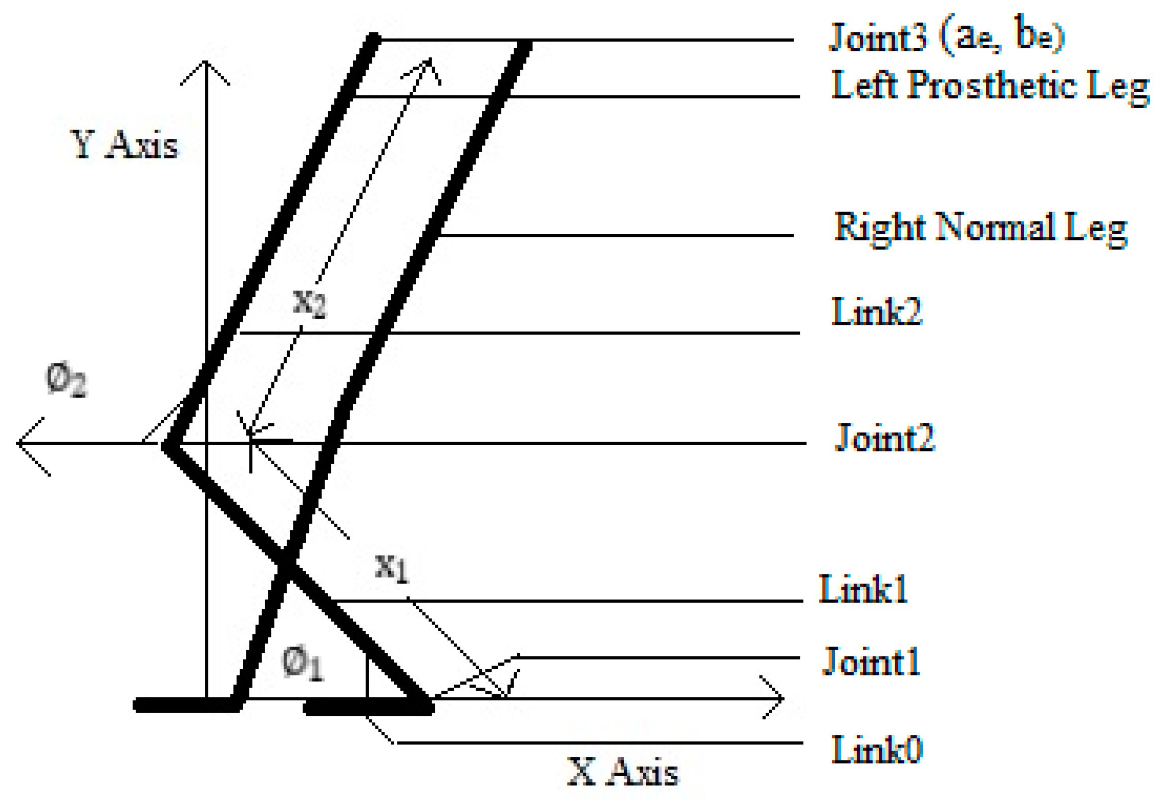
2.1. Technological System Design
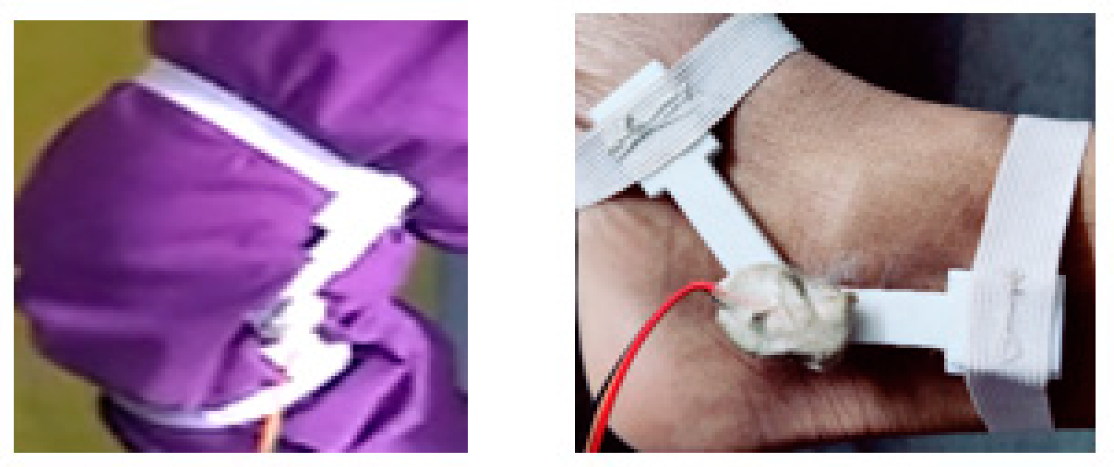
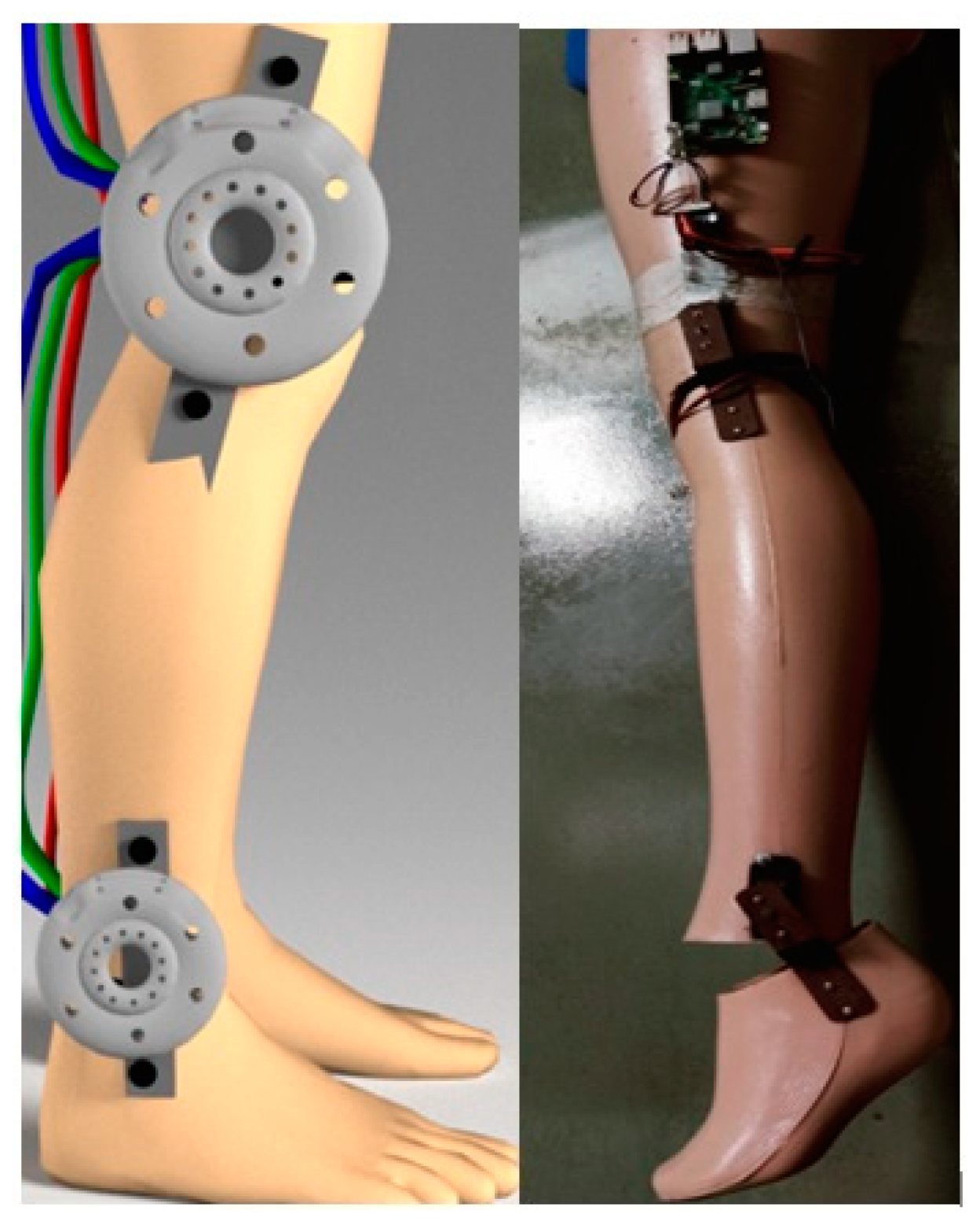
2.2. Embedded System Implementation of an Artificial Lower Limb
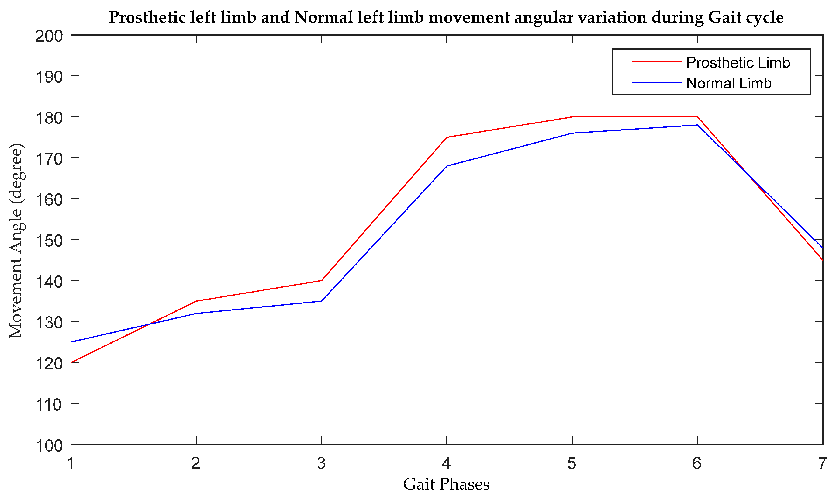
2.3. Gait Synchronization Process
3. Results and Discussion
3.1. The Sitting Condition as Case I (17.5 Inches from the Floor)
3.2. The Standing Condition as Case II
3.3. Characteristic Equation Generation of Designed Prosthetic Limb from Jacobian Matrix
3.4. Lyapunov Stability Analysis of Designed Prosthetic Lower Limb
4. Conclusions and Future Scopes
Author Contributions
Funding
Institutional Review Board Statement
Informed Consent Statement
Data Availability Statement
Acknowledgments
Conflicts of Interest
References
- de Miguel-Fernández, J.; Lobo-Prat, J.; Prinsen, E.; Font-Llagunes, J.M.; Marchal-Crespo, L. Control strategies used in lower limb exoskeletons for gait rehabili-tation after brain injury: A systematic review and analysis of clinical effectiveness. J. Neuroeng. Rehabil. 2023, 20, 23. [Google Scholar] [CrossRef] [PubMed]
- Tran, M.; Gabert, L.; Hood, S.; Lenzi, T. A lightweight robotic leg prosthesis replicating the biomechanics of the knee, ankle, and toe joint. Sci. Robot. 2022, 7, eabo3996. [Google Scholar] [CrossRef] [PubMed]
- Yu, C.; Ye, J.; Jia, J.; Zhao, X.; Chen, Z.; Chen, J. Design, Synthesis, and Experiment of Foot-Driven Lower Limb Rehabilitation Mechanisms. J. Mech. Robot. 2021, 14, 021001. [Google Scholar] [CrossRef]
- Asif, M.; Tiwana, M.I.; Khan, U.S.; Qureshi, W.S.; Iqbal, J.; Rashid, N.; Naseer, N. Advancements, Trends and Future Prospects of Lower Limb Prosthesis. IEEE Access 2021, 9, 85956–85977. [Google Scholar] [CrossRef]
- Penzlin, B.; Bergmann, L.; Li, Y.; Ji, L.; Leonhardt, S.; Ngo, C. Design and First Operation of an Active Lower Limb Exoskel-eton with Parallel Elastic Actuation. Actuators 2021, 10, 75. [Google Scholar] [CrossRef]
- Azizi, M.R.; Rastegarpanah, A.; Stolkin, R. Motion Planning and Control of an Omnidirectional Mobile Robot in Dynamic Environments. Robotics 2021, 10, 48. [Google Scholar] [CrossRef]
- Zhang, Y.; Wang, E.; Wang, M.; Liu, S.; Ge, W. Design and Experimental Research of Knee Joint Prosthesis Based on Gait Acquisition Technology. Biomimetics 2021, 6, 28. [Google Scholar] [CrossRef] [PubMed]
- Das, S.; Nandi, D.; Neogi, B. A Gait Synchronized and Body Kinesics Controlled Prosthetic System for Lower Extremity Ampu-Tation. Patent 202131050624A, 16 June 2022. [Google Scholar]
- Abu-Dakka, F.J.; Valera, A.; Escalera, J.A.; Abderrahim, M.; Page, A.; Mata, V. Passive Exercise Adaptation for Ankle Rehabilitation Based on Learning Control Framework. Sensors 2020, 20, 6215. [Google Scholar] [CrossRef] [PubMed]
- Park, K.; Ahn, H.-J.; Lee, K.-H.; Lee, C.-H. Development and Performance Verification of a Motorized Prosthetic Leg for Stair Walking. Appl. Bionics Biomech. 2020, 2020, 8872362. [Google Scholar] [CrossRef] [PubMed]
- Das, S.; Das, D.N.; Neogi, B. Design Approach for Artificial Human Ankle Movement. In Proceedings of the 2019 Devices for Integrated Circuit (DevIC), Kalyani, India, 23–24 March 2019; pp. 404–407. [Google Scholar] [CrossRef]
- Shi, D.; Zhang, W.; Zhang, W.; Ding, X. A Review on Lower Limb Rehabilitation Exoskeleton Robots. Chin. J. Mech. Eng. 2019, 32, 74. [Google Scholar] [CrossRef] [Green Version]
- Zahedi, M.S.; Stech, N.; Moser, D.; Sykes, A.J. Lower Limb Prosthesis with Knee Flexion Control During Descent of A Downward Incline. US Patent 10,285,827, 14 May 2019. [Google Scholar]
- Das, S.; Das, D.N.; Neogi, B. Lower Limb Movement Analysis for Exoskeleton Design. In Proceedings of the 2019 IEEE Region 10 Symposium (TENSYMP), Kolkata, India, 7–9 June 2019; pp. 759–764. [Google Scholar] [CrossRef]
- Du, Y.; Wang, H.; Qiu, S.; Yao, W.; Xie, P.; Chen, X. An Advanced Adaptive Control of Lower Limb Rehabilitation Ro-bot. Front. Robot. AI 2018, 5, 116. [Google Scholar] [CrossRef] [PubMed] [Green Version]
- Fairley, J.; Warder, H.; Coutts, J. Modular Lower Limb Prosthesis System. US Patent App. 15/947,444, 11 October 2018. [Google Scholar]
- Maddison, R.; Gemming, L.; Monedero, J.; Bolger, L.; Belton, S.; Issartel, J.; Marsh, S.; Direito, A.; Solenhill, M.; Zhao, J.; et al. Quantifying Human Movement Using the Moven Smartphone App: Validation and Field Study. JMIR Mhealth Uhealth 2017, 5, e122. [Google Scholar] [CrossRef] [PubMed]
- Cherelle, P.; Grosu, V.; Flynn, L.; Junius, K.; Moltedo, M.; Vanderborght, B.; Lefeber, D. The Ankle Mimicking Prosthetic Foot 3—Locking mechanisms, actuator design, control and experiments with an amputee. Robot. Multibody Mech. Dep. Mech. Eng. Vrije Univ. Bruss. Belg. Flanders Make Bel-Gium Robot. Auton. Syst. 2017, 91, 327–336. [Google Scholar] [CrossRef]
- Mortazavi, F.; Nadian-Ghomsheh, A. Stability of Kinect for range of motion analysis in static stretching exercises. PLoS ONE 2018, 13, e0200992. [Google Scholar] [CrossRef] [PubMed]
- Piazza, C.; Della Santina, C.; Gasparri, G.M.; Catalano, M.G.; Grioli, G.; Garabini, M.; Bicchi, A. Toward an adaptive foot for natural walking. In Proceedings of the 16th IEEE-RAS International Conference on Humanoid Robots, Cancun, Mexico, 15–17 November 2016; pp. 1204–1210. [Google Scholar]
- Koller, J.R.; Jacobs, D.A.; Ferris, D.P.; Remy, C.D. Learning to walk with an adaptive gain proportional myoelectric controller for a robotic ankle exoskeleton. J. Neuroeng. Rehabil. 2015, 12, 97. [Google Scholar] [CrossRef] [PubMed] [Green Version]
- Liu, Z.; Huang, D.; Xing, Y.; Zhang, C.; Wu, Z.; Ji, X. New Trends in Non-linear Control Systems and Applications. Abstr. Appl. Anal. 2015, 2015, 637632. [Google Scholar] [CrossRef] [Green Version]
- Kawakami, T.; Hosoda, K. Bipedal walking with oblique mid-foot joint in foot. In Proceedings of the IEEE International Conference on Robotics and Biomimetics, Zhuhai, China, 6–9 December 2015; pp. 535–540. [Google Scholar]
- Khansari-Zadeh, S.M.; Billard, A. Learning Control Lyapunov Function to Ensure Stability of Dynamical System-based Robot Reaching Motions. Robot. Auton. Syst. 2014, 62, 752–765. [Google Scholar] [CrossRef] [Green Version]


| SL. No. | Gait Phases | Movement Angle of the Normal Right Limb (Degree) | Movement Angle of the Prosthetic Left Limb (Degree) | Movement Angle in the Normal Left Limb (Degree) | Angular Deviation between Prosthetic Left Limb and Normal Left Limb (Degree) | ||||
|---|---|---|---|---|---|---|---|---|---|
| Knee Joint (R.Eknee) | Ankle Joint (R.Eankle) | Knee Joint (Mknee) | Ankle Joint (Mankle) | Knee Joint | Ankle Joint | Knee Joint | Ankle Joint | ||
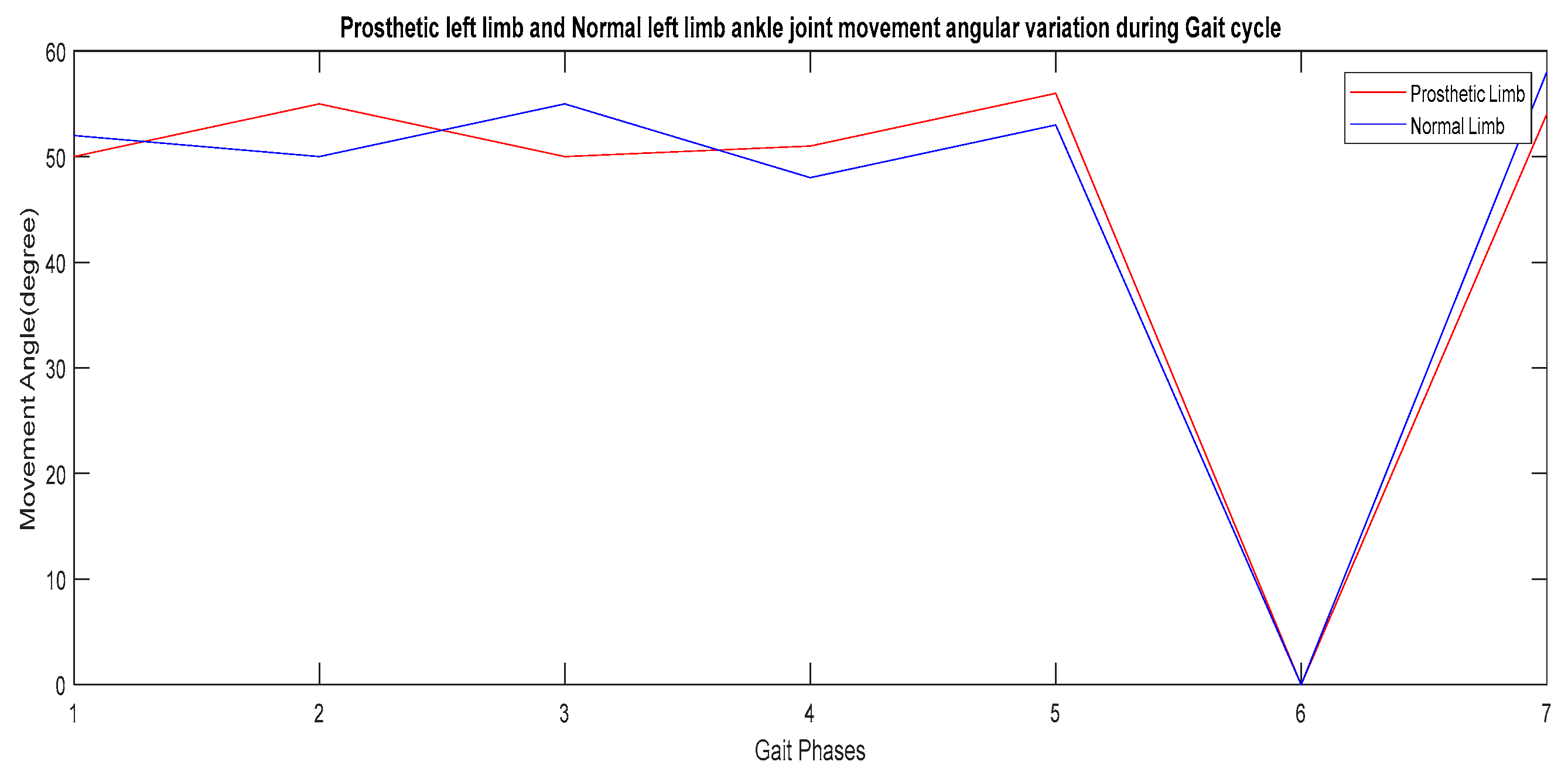
| 1 | Heel strike | 180 | 20 | 120 | 50 | 125 | 52 | 5 | 2 |
| 2 | Foot flat | 170 | 0 | 135 | 55 | 132 | 50 | 3 | 5 |
| 3 | Midstance | 180 | 2 | 140 | 50 | 135 | 55 | 5 | 5 |
| 4 | Push off | 125 | 54 | 175 | 51 | 168 | 48 | 7 | 3 |
| 5 | Acceleration | 140 | 51 | 180 | 56 | 176 | 53 | 4 | 3 |
| 6 | Mid-swing | 125 | 50 | 180 | 0 | 178 | 0 | 2 | 0 |
| 7 | Deceleration | 180 | 18 | 145 | 54 | 148 | 58 | 3 | 4 |
| Sl. No. | Gait Phases | Movement Output of the Normal Right Limb (Volt) | Movement Output of the Prosthetic Left Limb (Volt) | Movement Output in the Normal Left Limb (Volt) | Output Deviation between Prosthetic Left Limb and Normal Left Limb (Volt) | ||||
|---|---|---|---|---|---|---|---|---|---|
| Knee Joint (R.Eknee) | Ankle Joint (R.Eankle) | Knee Joint (Mknee) | Ankle Joint (Mankle) | Knee Joint | Ankle Joint | Knee Joint | Ankle Joint | ||
| 1 | Heelstrike | 5.1 | 5.1 | 5.5 | 5.3 | 5.7 | 5.0 | 0.2 | 0.3 |
| 2 | Footflat | 5.0 | 5.2 | 5.1 | 5.1 | 5.0 | 5.5 | 0.1 | 0.4 |
| 3 | Midstance | 4.9 | 6.2 | 5.2 | 5.1 | 5.4 | 5.3 | 0.2 | 0.2 |
| 4 | Pushoff | 4.9 | 4.9 | 5.3 | 5.2 | 5.2 | 5.2 | 0.1 | 0.0 |
| 5 | Acceleration | 4.9 | 4.1 | 5.4 | 5.4 | 5.4 | 5.2 | 0.0 | 0.2 |
| 6 | Mid-swing | 4.8 | 4.2 | 5.6 | 5.2 | 5.3 | 5.3 | 0.3 | 0.1 |
| 7 | Deceleration | 4.9 | 4.2 | 5.5 | 5.3 | 5.4 | 5.3 | 0.3 | 0.2 |
| SL. No. | Posture Condition of Limb | Length of Lower Link (Inches) | Length of Upper Link (Inches) | Angle of Lower Link (Degrees) | Angle of Lower Link (Degrees) |
|---|---|---|---|---|---|
| 01 | Sitting | 16 | 18 | 52 | 22 |
| 02 | Standing | 16 | 18 | 87 | 89 |
| Tuning Condition | Rise Time (Seconds) | Settling Time (Seconds) | Overshoot (%) | Peak | Proportional Constant (Kp) | Integral Constant (Ti) | Derivative Constant (Kd) | Response Time (Seconds) | Transient Behavior |
|---|---|---|---|---|---|---|---|---|---|
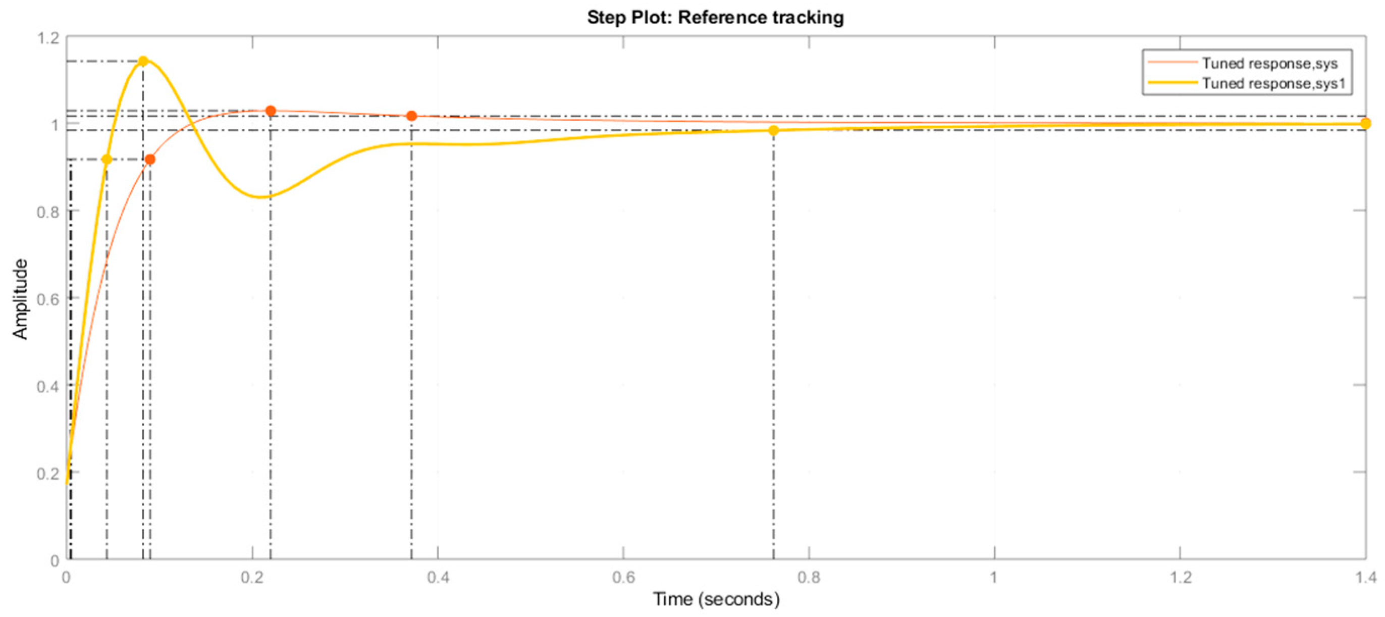
| Without tuning | 0.0302 | 0.798 | 117 | 0.681 | 1.1864 | NA | NA | 0.3515 | 0.6 |
| With tuning | 0.0393 | 0.762 | 14.2 | 1.14 | 0.41239 | 0.0084228 | 0 | 0.05571 | 0.6 |
Disclaimer/Publisher’s Note: The statements, opinions and data contained in all publications are solely those of the individual author(s) and contributor(s) and not of MDPI and/or the editor(s). MDPI and/or the editor(s) disclaim responsibility for any injury to people or property resulting from any ideas, methods, instructions or products referred to in the content. |
© 2023 by the authors. Licensee MDPI, Basel, Switzerland. This article is an open access article distributed under the terms and conditions of the Creative Commons Attribution (CC BY) license (https://creativecommons.org/licenses/by/4.0/).
Share and Cite
Das, S.; Nandi, D.; Neogi, B. Design Analysis of Prosthetic Unilateral Transtibial Lower Limb with Gait Coordination. Prosthesis 2023, 5, 575-586. https://doi.org/10.3390/prosthesis5020040
Das S, Nandi D, Neogi B. Design Analysis of Prosthetic Unilateral Transtibial Lower Limb with Gait Coordination. Prosthesis. 2023; 5(2):575-586. https://doi.org/10.3390/prosthesis5020040
Chicago/Turabian StyleDas, Susmita, Dalia Nandi, and Biswarup Neogi. 2023. "Design Analysis of Prosthetic Unilateral Transtibial Lower Limb with Gait Coordination" Prosthesis 5, no. 2: 575-586. https://doi.org/10.3390/prosthesis5020040