
Autonomously Steering Vehicles along Unmarked Roads Using Low-Cost Sensing and Computational Systems

Abstract
:1. Introduction
2. Materials and Methods
2.1. Solution Methodology
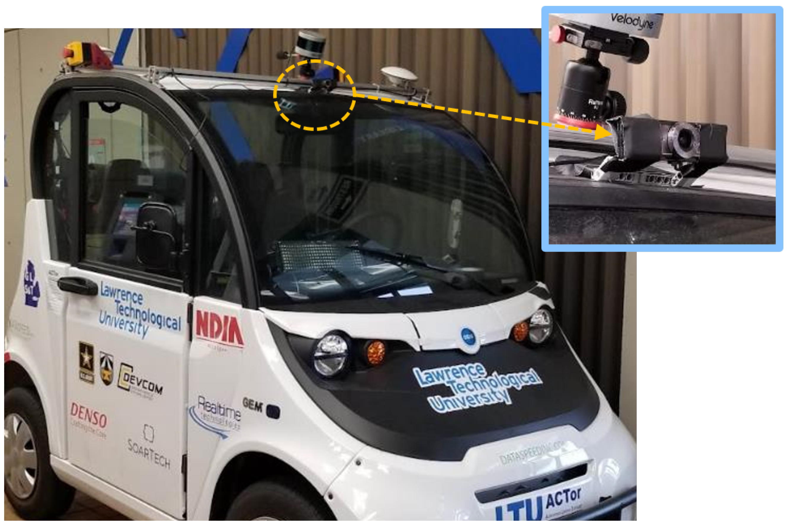
2.2. Hardware
2.3. Software
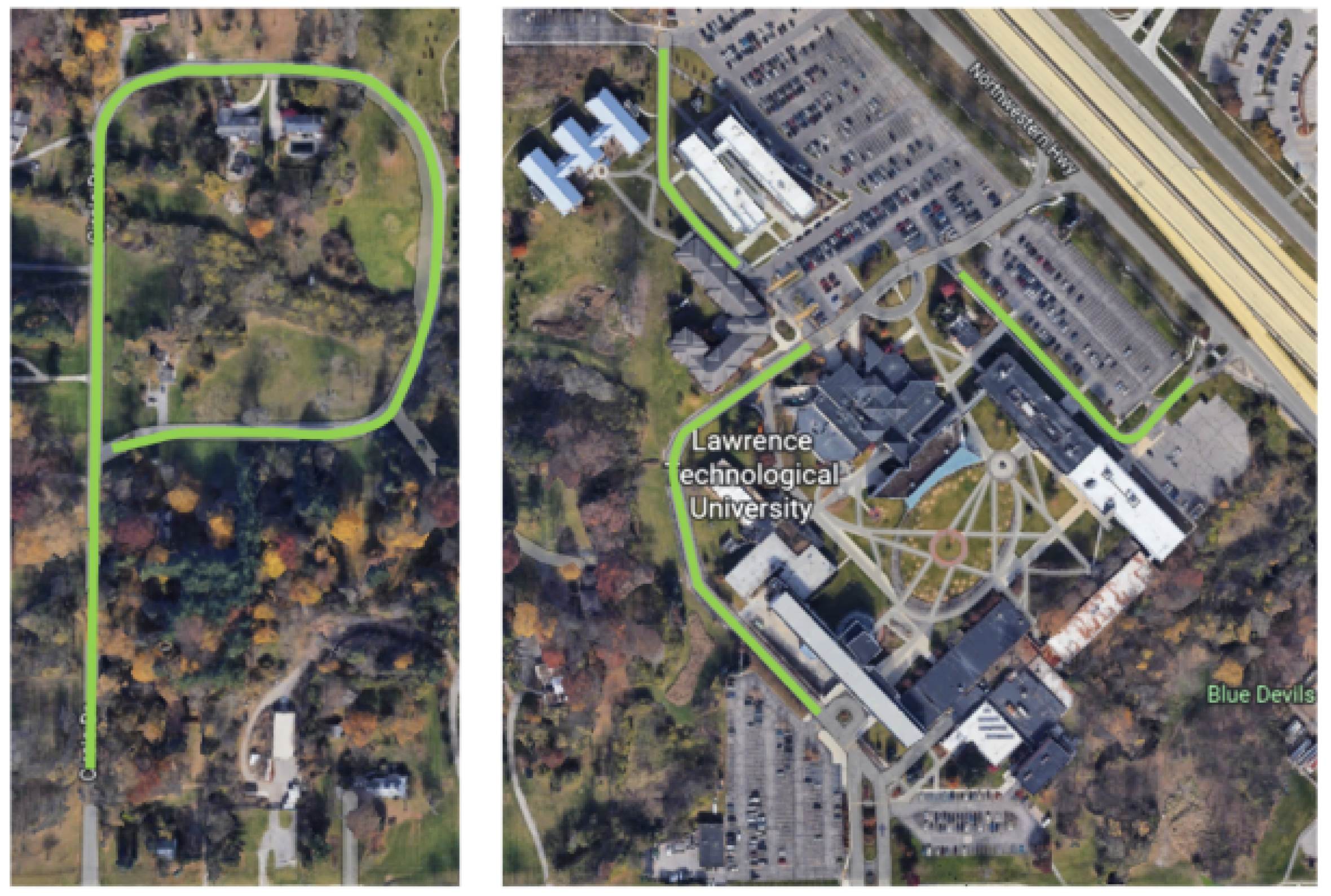
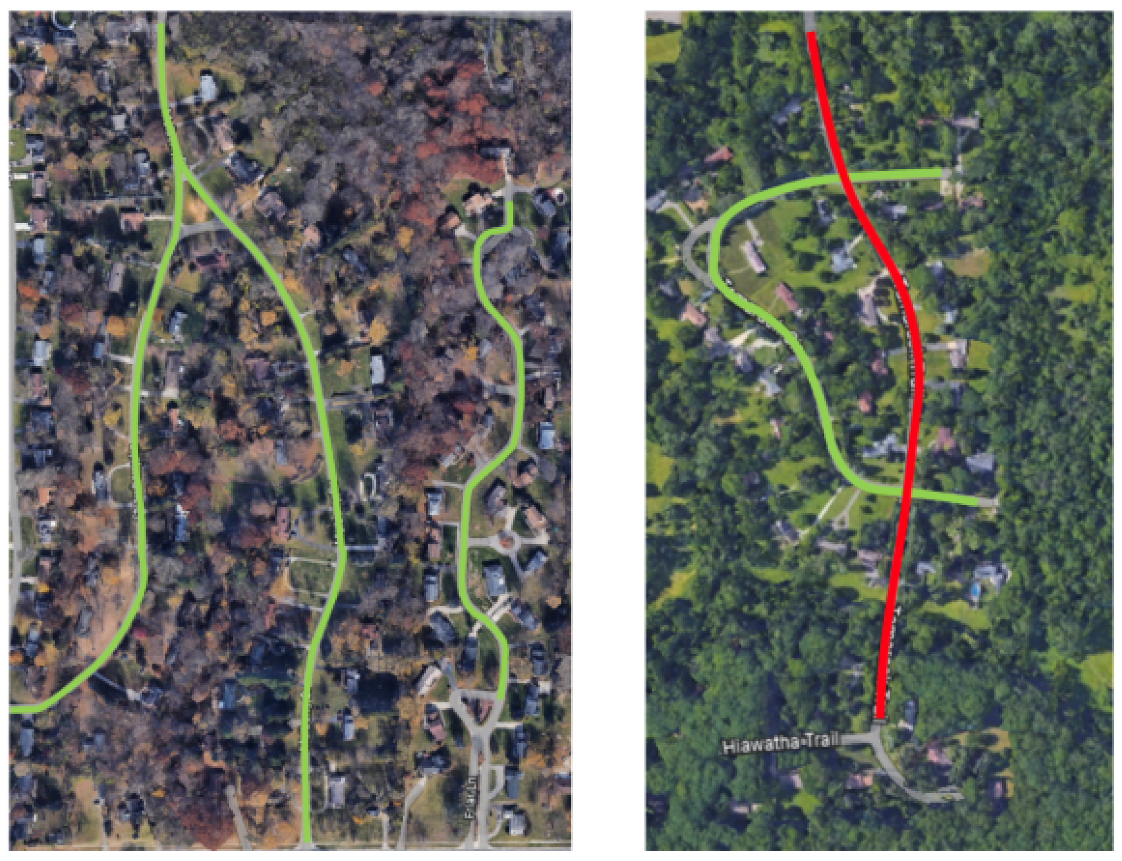
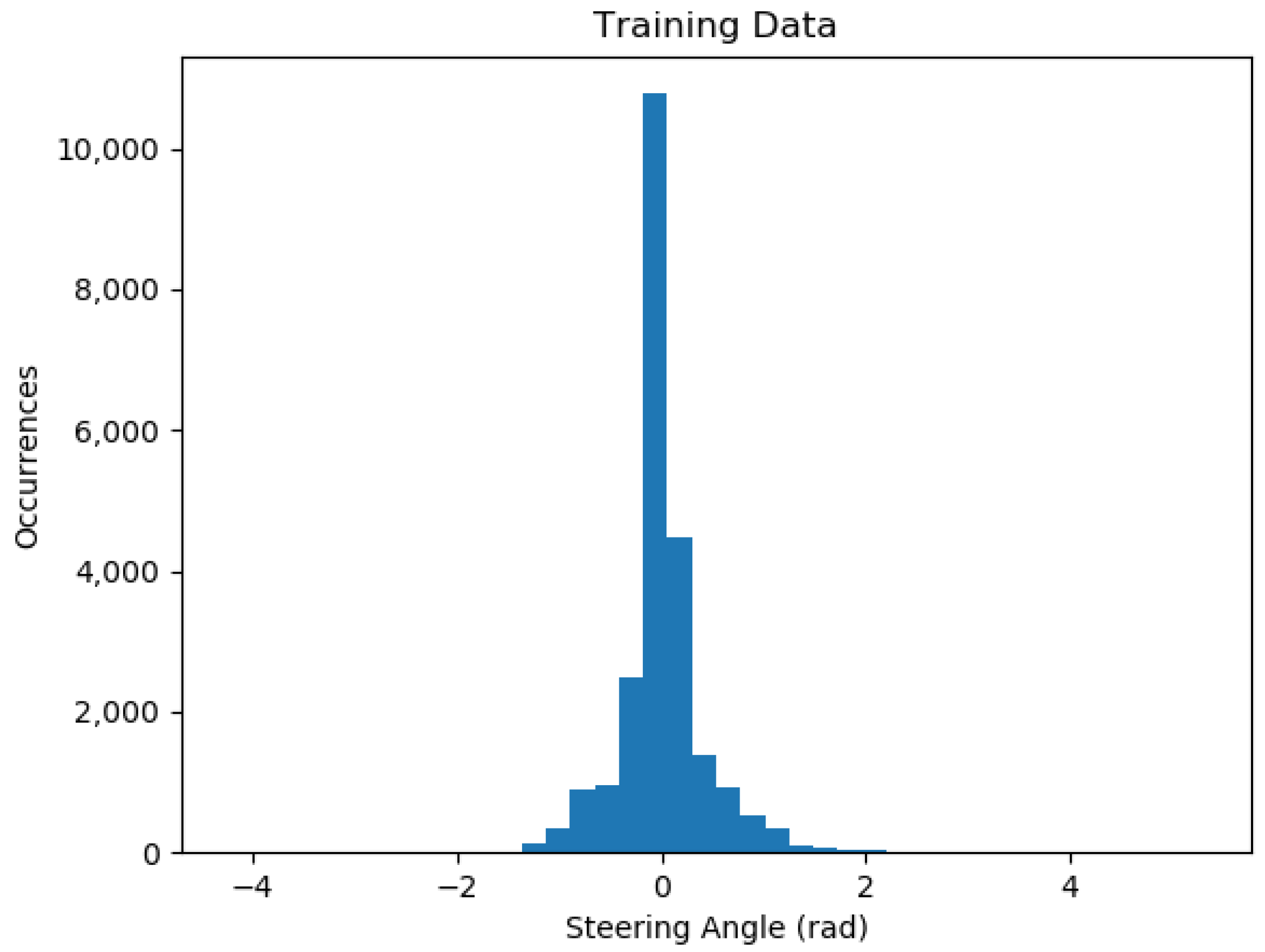
3. Data Collection
- Camera Publishing Node: Receives forward-facing images sent by the Genius webcam and publishes the images to the ROS network.
- Steering Wheel Report Node: Interfaces with the DataSpeed drive-by-wire system and publishes the current steering wheel angle.
- Steering Data Collection Node: Receives webcam images and steering wheel angle data, down-samples the webcam image, and saves the image and steering wheel angle to a file.
4. Model Structure and Training Methodology
4.1. Model Structure
4.2. Model Training Methodology
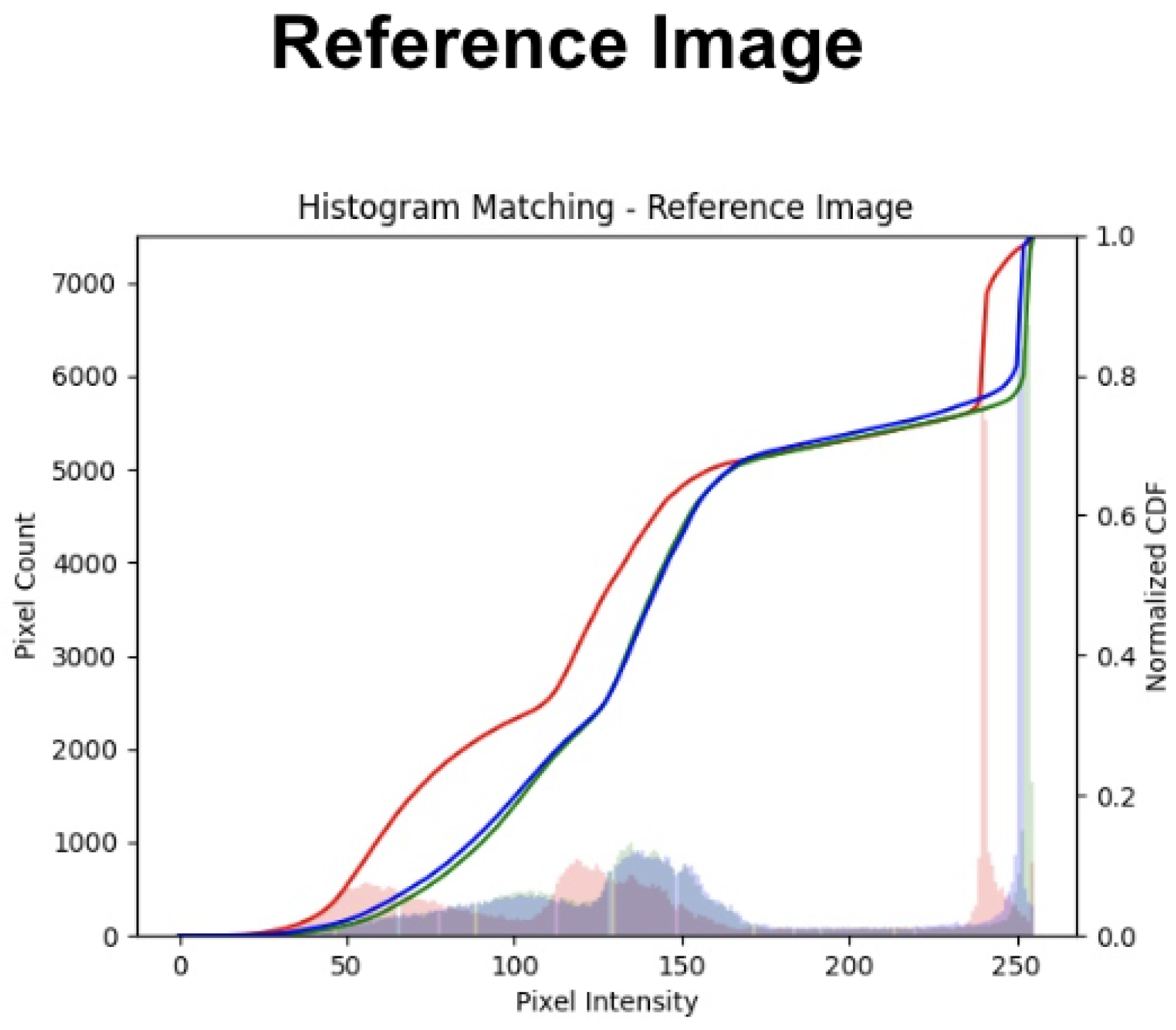
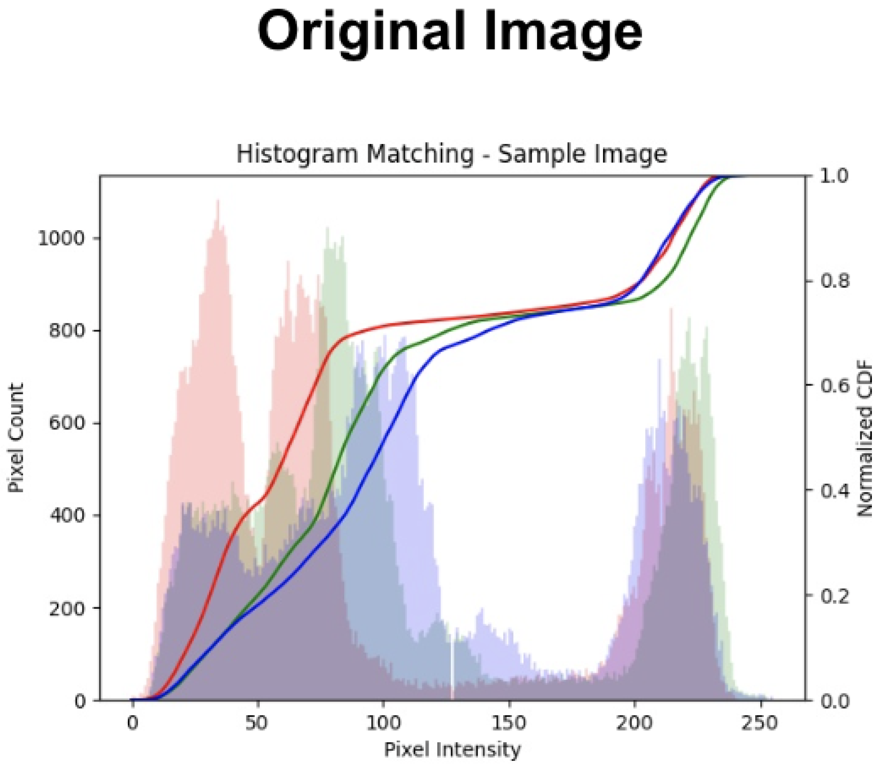
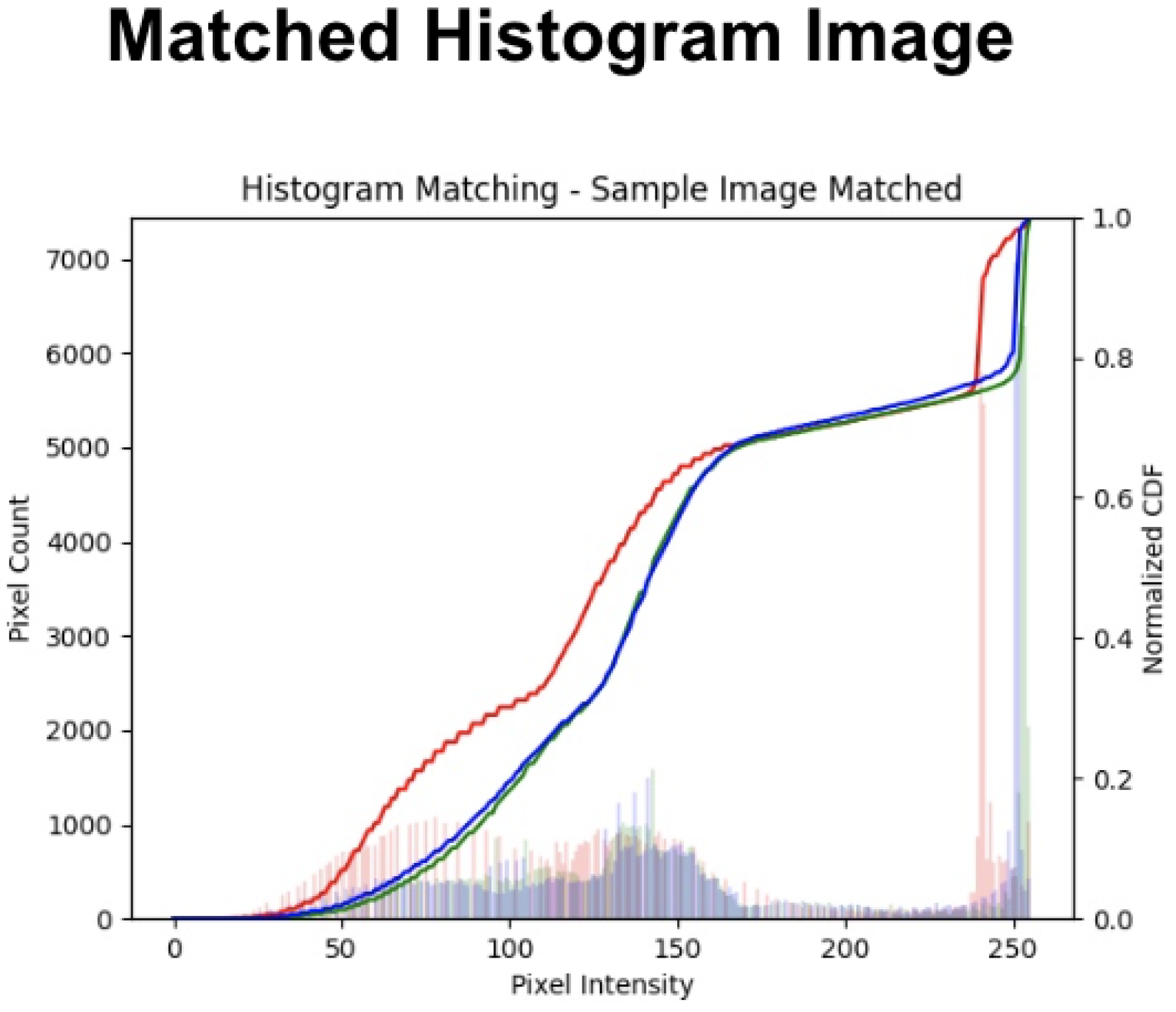
- Obtain the histogram for both the input image and a reference image:
- Calculate the Cumulative Distribution Function (CDF) for both the input image and the reference image.
- Calculate the transformation T to map the old intensity values to the new intensity values for both the input image and reference image:
- Use the transformed intensity values for both the input image and reference image to map the intensity values of the input image to the new values.
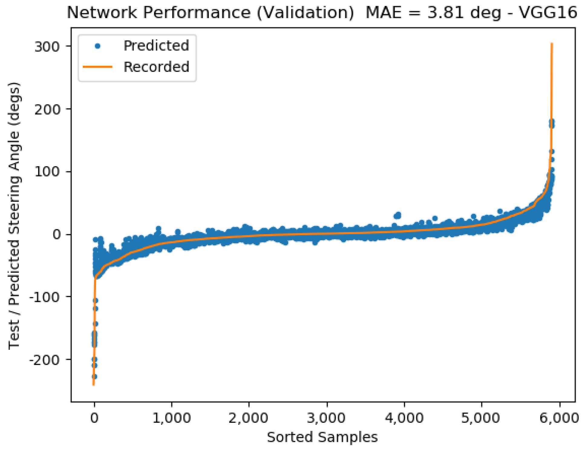
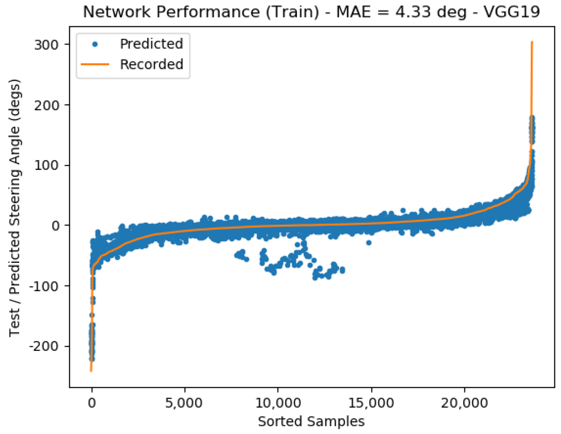
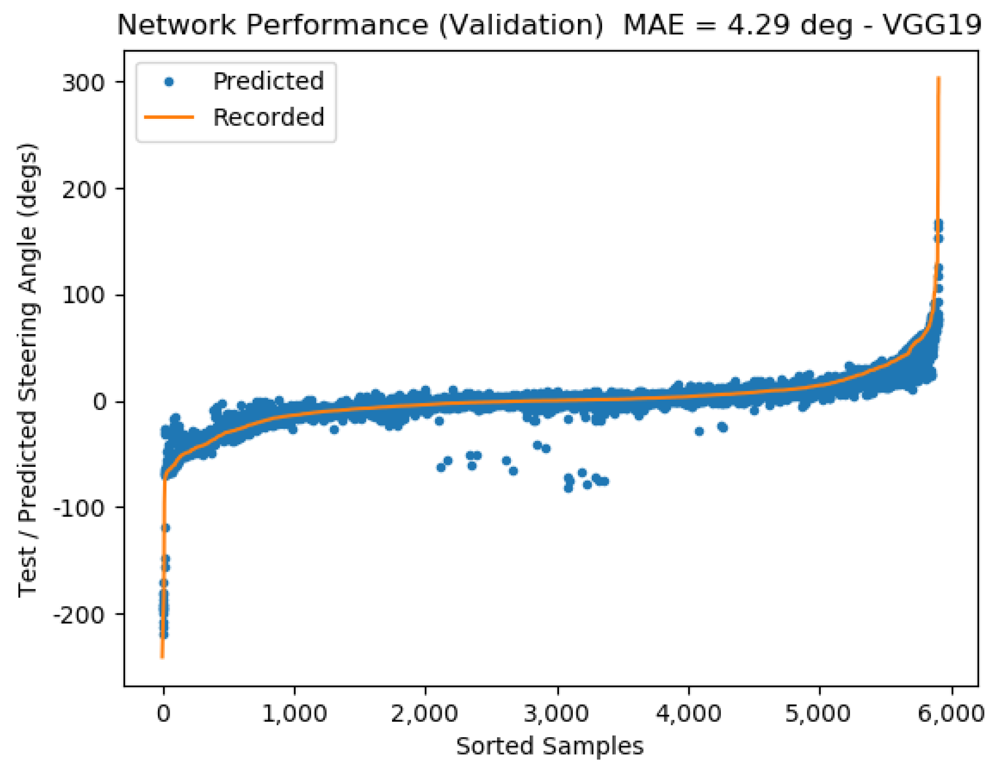
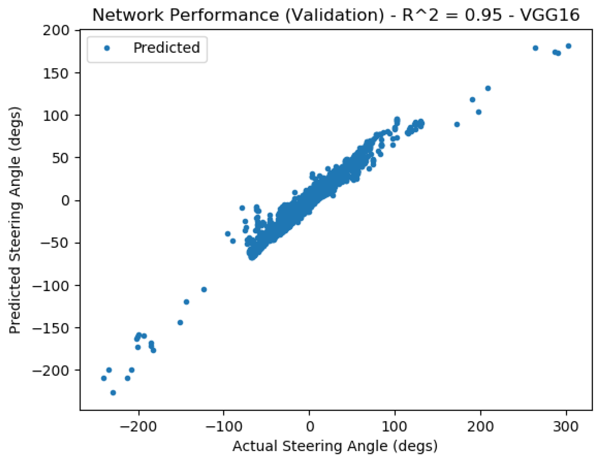
5. Results
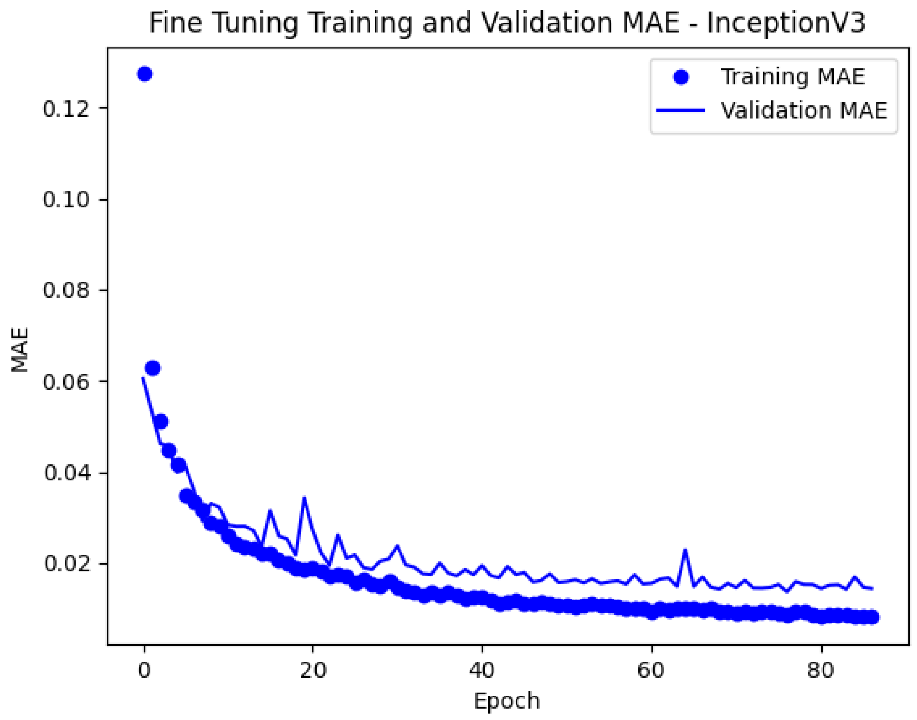
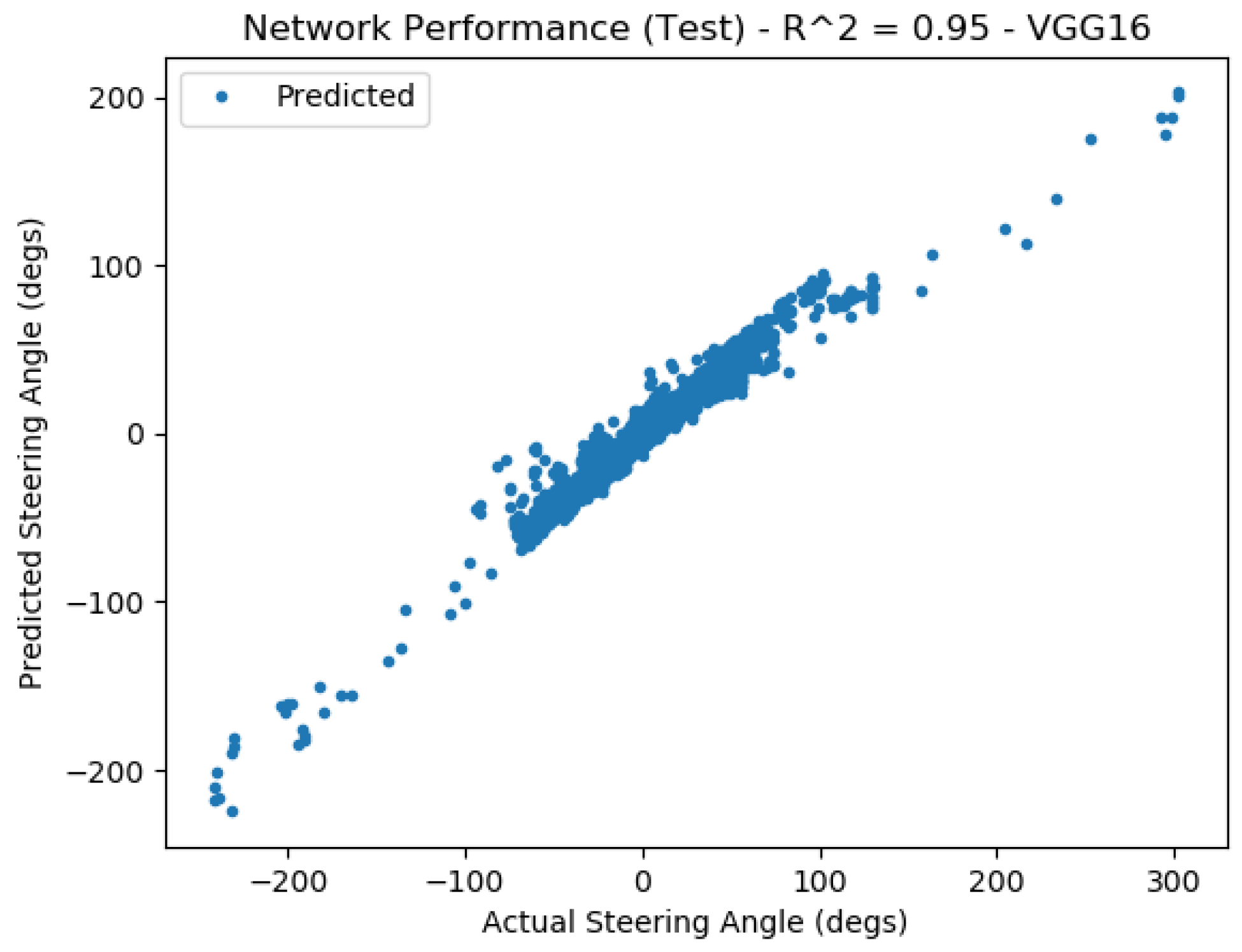
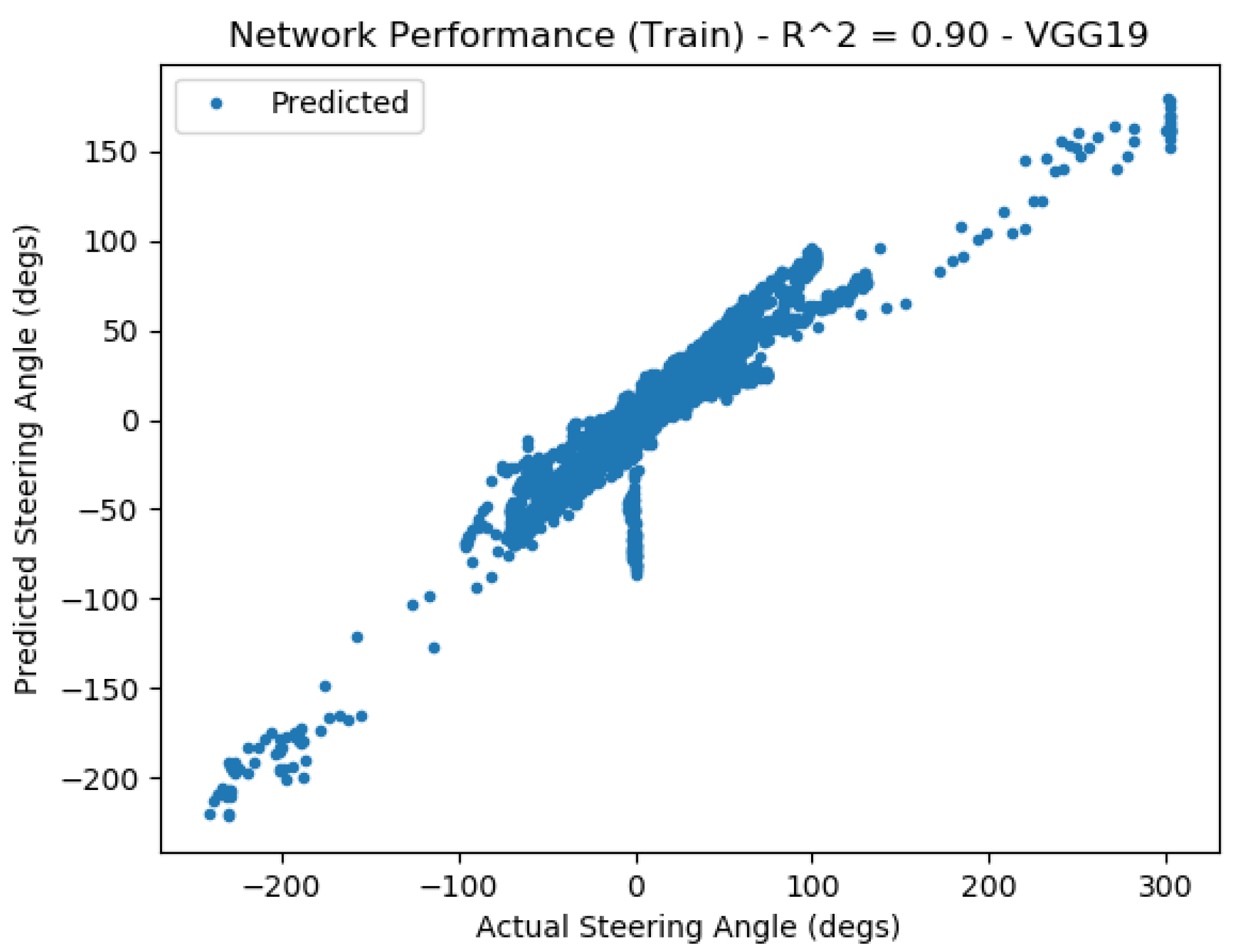
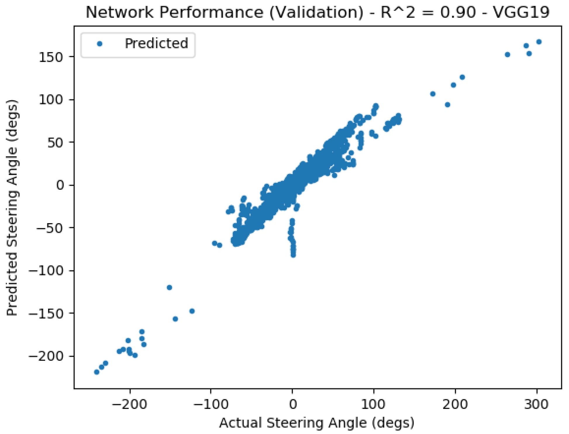
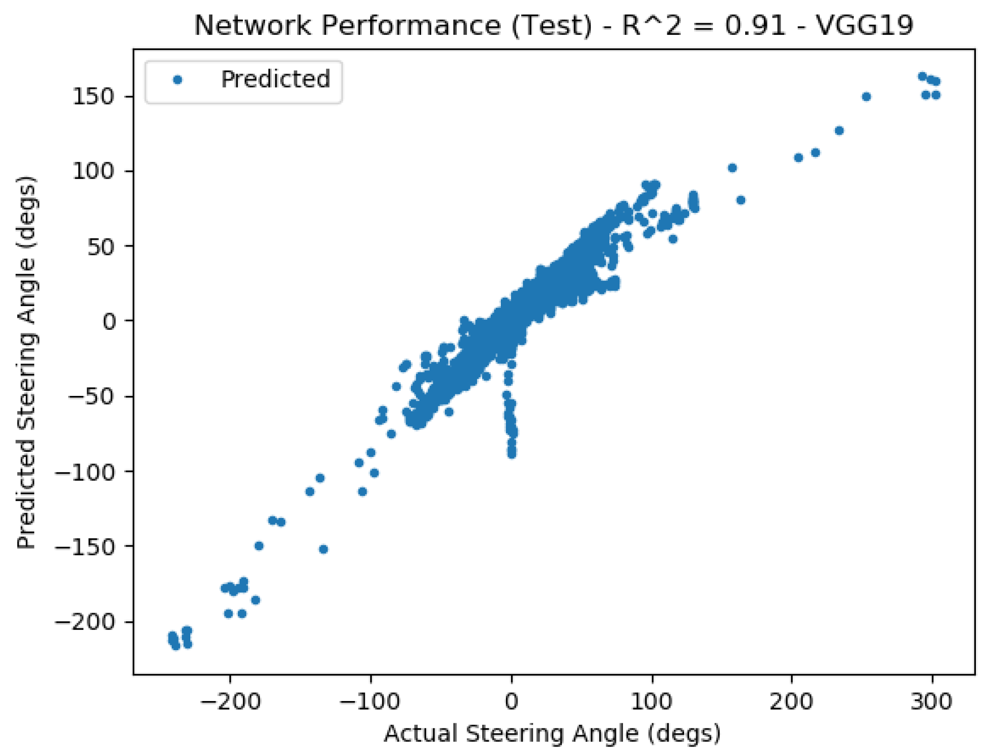
5.1. Model Training Results
5.2. Model Application Results—Self-Drive with Inference
- Camera Publishing Node: Receives forward-facing images sent by the Genius webcam and publishes the images to the ROS network (the same node used the Data Collection implementation).
- Steering Node: Receives images from the webcam, down-samples the images, applies histogram matching, evaluates the neural network, and publishes the desired steering wheel angle.
- Steering Wheel Driver Node: Publishes desired steering wheel angle to the DataSpeed drive-by-wire system to actuate the ACTor steering system.
5.3. Leveraging Recurrent Neural Networks
6. Future Work
7. Conclusions
Author Contributions
Funding
Institutional Review Board Statement
Informed Consent Statement
Data Availability Statement
Acknowledgments
Conflicts of Interest
Abbreviations
| ACTor | Autonomous Campus Transport |
| ALVINN | Autonomous Land Vehicle In a Neural Network |
| ANN | Artificial Neural Network |
| CNN | Convolutional Neural Network |
| MAE | Mean Absolute Error |
| MSE | Mean-Squared Error |
| RMS | Root Mean Square |
| RNN | Recurrent Neural Network |
| ROS | Robotic Operating System |
| SGD | Stochastic Gradient Descent |
| SWA | Steering Wheel Angle |
Appendix A


Appendix B


Appendix C


References
- Pomerleau, D.A. Alvinn: An Autonomous Land Vehicle in a Neural Network. In Advances in Neural Information Processing Systems. 1988. Available online: https://proceedings.neurips.cc/paper/1988/file/812b4ba287f5ee0bc9d43bbf5bbe87fb-Paper.pdf (accessed on 31 July 2023).
- Wang, Y.; Shen, D.; Teoh, E.K. Lane detection using spline model. Pattern Recognit. Lett. 2000, 21, 677–689. [Google Scholar] [CrossRef]
- Wang, Y.; Teoh, E.K.; Shen, D. Lane detection and tracking using b-snake. Image Vis. Comput. 2004, 22, 269–280. [Google Scholar] [CrossRef]
- Ian Timmis, N.P.; Chung, C.J. Teaching vehicles to steer themselves with deep learning. In Proceedings of the 2021 IEEE In-ternational Conference on Electro Information Technology (EIT), Mt. Pleasant, MI, USA, 14–15 May 2021. [Google Scholar]
- Quigley, M. ROS: An open-source Robot Operating System. In Proceedings of the ICRA Workshop on Open Source Software, Kobe, Japan, 12–17 May 2009; Volume 3. [Google Scholar]
- Robotic Operating System. Available online: https://www.ros.org (accessed on 31 July 2023).
- Gillespie, T.D. Fundamentals of Vehicle Dynamics; Premiere Series Books; SAE International: Warrendale, PA, USA, 1992. [Google Scholar]
- Szegedy, C.; Vanhoucke, V.; Ioffe, S.; Shlens, J.; Wojna, Z. Rethinking the Inception Architecture for Computer Vision. CoRR arXiv 2015, arXiv:1512.00567. [Google Scholar]
- Simonyan, K.; Zisserman, A. Very Deep Convolutional Networks for Large-Scale Image Recognition. In Proceedings of the International Conference on Learning Representations, San Diego, CA, USA, 7–9 May 2015. [Google Scholar]
- Chollet, F. Deep Learning with Python; Simon and Schuster: New York, NY, USA, 2018. [Google Scholar]
- Li, Z.; Hoiem, D. Learning Without Forgetting. In Proceedings of the European Conference on Computer Vision, Amsterdam, The Netherlands, 8–16 October 2016; Springer: Berlin/Heidelberg, Germany, 2016; pp. 614–629. [Google Scholar]
- Kathuria, A. Intro to Optimization in Deep Learning: Momentum, RMSPROP and Adam. Available online: https://blog.paperspace.com/intro-to-optimization-momentum-rmsprop-adam (accessed on 31 July 2023).
- Brownlee, J. How to Checkpoint Deep Learning Models in Keras. Available online: https://machinelearningmastery.com/check-point-deep-learning-models-keras. (accessed on 31 July 2023).
- Addison, A. Difference between Histogram Equalization and Histogram Matching. Available online: https://automaticaddison.com/difference-between-histogram-equalization-and-histogram-matching. (accessed on 31 July 2023).
- Shapira, D.; Avidan, S.; Hel-Or, Y. Multiple histogram matching. In Proceedings of the 2013 IEEE International Conference on Image Processing, Melbourne, Australia, 15–18 September 2013. [Google Scholar]
- Chung, C.J.; DeRose, G. 2023. Available online: https://youtu.be/aZJaIr5ilos (accessed on 31 July 2023).
- Chung, C.J.; Ramsey, A. 2023. Available online: https://youtu.be/yGqs5YsmQiU (accessed on 31 July 2023).


| Training | Validation | Testing | Application |
|---|---|---|---|
| 23,623 | 5906 | 7383 | 7692 |
| InceptionV3 | VGG16 | VGG19 | |
|---|---|---|---|
| Training | 2.96 | 3.82 | 4.33 |
| Validation | 3.08 | 3.81 | 4.29 |
| Testing | 3.10 | 3.88 | 4.41 |
| InceptionV3 | VGG16 | VGG19 | |
|---|---|---|---|
| Train | 0.97 | 0.95 | 0.91 |
| Validation | 0.97 | 0.94 | 0.90 |
| Testing | 0.97 | 0.94 | 0.90 |
| Recurrent Neural Network | |
|---|---|
| Training | 2.51 |
| Validation | 2.64 |
| Testing | 2.67 |
| Test Route | 3.82 |
Disclaimer/Publisher’s Note: The statements, opinions and data contained in all publications are solely those of the individual author(s) and contributor(s) and not of MDPI and/or the editor(s). MDPI and/or the editor(s) disclaim responsibility for any injury to people or property resulting from any ideas, methods, instructions or products referred to in the content. |
© 2023 by the authors. Licensee MDPI, Basel, Switzerland. This article is an open access article distributed under the terms and conditions of the Creative Commons Attribution (CC BY) license (https://creativecommons.org/licenses/by/4.0/).
Share and Cite
DeRose, G., Jr.; Ramsey, A.; Dombecki, J.; Paul, N.; Chung, C.-J. Autonomously Steering Vehicles along Unmarked Roads Using Low-Cost Sensing and Computational Systems. Vehicles 2023, 5, 1400-1422. https://doi.org/10.3390/vehicles5040077
DeRose G Jr., Ramsey A, Dombecki J, Paul N, Chung C-J. Autonomously Steering Vehicles along Unmarked Roads Using Low-Cost Sensing and Computational Systems. Vehicles. 2023; 5(4):1400-1422. https://doi.org/10.3390/vehicles5040077
Chicago/Turabian StyleDeRose, Giuseppe, Jr., Austin Ramsey, Justin Dombecki, Nicholas Paul, and Chan-Jin Chung. 2023. "Autonomously Steering Vehicles along Unmarked Roads Using Low-Cost Sensing and Computational Systems" Vehicles 5, no. 4: 1400-1422. https://doi.org/10.3390/vehicles5040077