
Ride Comfort Improvements on Disturbed Railroads Using Model Predictive Control

Abstract
:1. Introduction
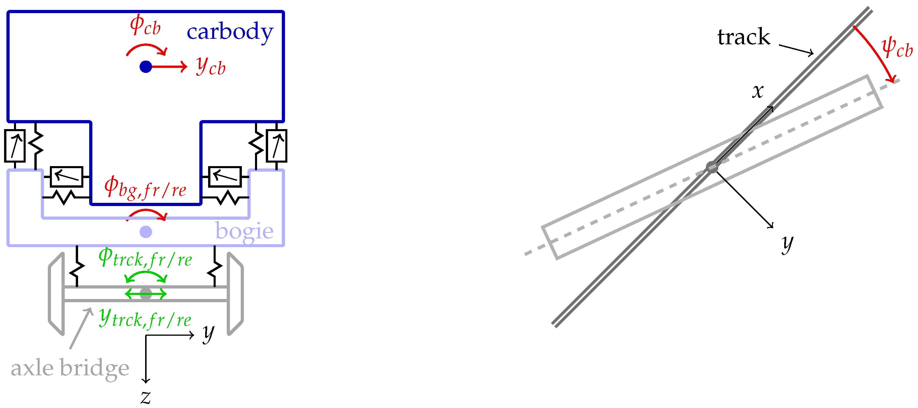
2. Modeling
- Due to the mechatronic guidance of NGT’s running gear, flange contact does not occur.
- Bumpstop contact can be avoided since MPC has the ability to handle state restrictions (e.g., suspension deflections).
- Small angles of roll and yaw are assumed.
3. Simulation Results
4. Discussion
5. Conclusions
Author Contributions
Funding
Institutional Review Board Statement
Data Availability Statement
Conflicts of Interest
Abbreviations
| NGT | Next-Generation Train. |
| TCN | Train communication network. |
| MPC | Model Predictive Control. |
| DIRW | Driven independently rotating wheels. |
| DOF | Degree of freedom. |
| w.r.t. | With respect to. |
| MBS | Multibody simulation |
| dist. | Distance |
| CoG | Center of gravity |
Appendix A


| Name | Description |
|---|---|
| Carbody mass | |
| Moment of inertia around x-axis, carbody | |
| Moment of inertia around z-axis, carbody | |
| Moment of inertia around x-axis, bogie | |
| Lateral stiffness secondary suspension | |
| Vertical stiffness secondary suspension | |
| Bending stiffness secondary suspension | |
| Cross-coupling stiffness secondary suspension | |
| Vertical stiffness primary suspension | |
| Lateral damping secondary suspension | |
| Vertical damping secondary suspension | |
| Vertical damping primary dampers | |
| Vertical damping primary suspension | |
| Half the distance between secondary springs | |
| Half the distance between secondary dampers | |
| Half the distance between primary springs | |
| Half the distance between primary dampers | |
| Half the distance between the center pivots | |
| Vertical dist. lateral damper to carbody CoG | |
| Vertical dist. secondary spring to carbody CoG | |
| Vertical dist. bogie CoG to secondary spring | |
| Nominal length secondary springs | |
| Preload of secondary springs due to carbody mass |
Appendix B
Appendix C

References
- Winter, J. Novel Rail Vehicle Concepts for a High Speed Train: The Next Generation Train. In Proceedings of the First International Conference on Railway Technology: Research, Development and Maintenance, Las Palmas de Gran Canaria, Spain, 18–20 April 2012; Civil-Comp Proceedings. Pombo, J., Ed.; Civil-Comp Press: Stirlingshire, UK, 2012. [Google Scholar] [CrossRef]
- Heckmann, A.; Keck, A.; Grether, G. Active Guidance of a Railway Running Gear with Independently Rotating Wheels. In Proceedings of the 2020 IEEE Vehicle Power and Propulsion Conference (VPPC), Piscataway, NJ, USA, 18 November–16 December 2020; pp. 1–5. [Google Scholar] [CrossRef]
- Heckmann, A.; Lüdicke, D.; Keck, A.; Goetjes, B. A Research Facility for the Next Generation Train Running Gear in True Scale. In Advances in Dynamics of Vehicles on Roads and Tracks II; Lecture Notes in Mechanical Engineering; Orlova, A., Cole, D., Eds.; Springer International Publishing: Cham, Switzerland, 2022; Volume 9, pp. 18–27. [Google Scholar] [CrossRef]
- European Union Agency for Railways. Technical Specifications for Interoperability—Control Command and Signalling. Technical Report CCS. Available online: https://www.era.europa.eu/domains/technical-specifications-interoperability/control-command-and-signalling-tsi_en (accessed on 27 May 2016).
- Ludicke, D.; Lehner, A. Train Communication Networks and Prospects. IEEE Commun. Mag. 2019, 57, 39–43. [Google Scholar] [CrossRef]
- International Electrotechnical Commission. Electronic Railway Equipment—Train communication Network (TCN)—Part 1: General Architecture; Technical Report 61375-1; International Electrotechnical Commission: Geneva, Switzerland, 2012. [Google Scholar]
- DIN EN 61375-1:2015-02, Elektronische Betriebsmittel für Bahnen—Zug-Kommunikations-Netzwerk (TCN)—Teil 1: Allgemeiner Aufbau (IEC 61375-1:2012); Deutsche Fassung EN 61375-1:2012; Technical Report; Deutsches Institut für Normung e.V.: Berlin, Germany, 2015. [CrossRef]
- Shift2Rail CONNECTA. Final Report on the Contribution of CONNECTA to Shift2Rail: Deliverable D8.3. Available online: https://projects.shift2rail.org/download.aspx?id=e489bd37-4ec1-4fbf-bd1d-818bb0fc0762 (accessed on 14 August 2023).
- Europe’s Rail. Home—Europe’s Rail. Available online: https://rail-research.europa.eu/ (accessed on 14 August 2023).
- Schindler, C.; Brandhorst, M.; Dellmann, T.; Haigermoser, A.; Hecht, M.; Karch, S.; Löffler, G.; Rösch, W. (Eds.) Handbuch Schienenfahrzeuge: Entwicklung, Produktion, Instandhaltung, 1. auflage ed.; Eurail Press: Hamburg, Germany, 2014. [Google Scholar]
- Fu, B.; Giossi, R.L.; Persson, R.; Stichel, S.; Bruni, S.; Goodall, R. Active suspension in railway vehicles: A literature survey. Railw. Eng. Sci. 2020, 28, 3–35. [Google Scholar] [CrossRef]
- Qazizadeh, A. On Active Suspension in Rail Vehicles. Ph.D. Thesis, KTH Royal Institute of Technology, Stockholm, Sweden, 2017. [Google Scholar]
- Orvnäs, A. Methods for Reducing Vertical Carbody Vibrations of a Rail Vehicle: A literature Survey; Järnvägsgruppen, KTH Railway Group: Stockholm, Sweden, 2010. [Google Scholar]
- Gohrle, C.; Wagner, A.; Schindler, A.; Sawodny, O. Active suspension controller using MPC based on a full-car model with preview information. In Proceedings of the 2012 American Control Conference (ACC), Montreal, QC, Canada, 27–29 June 2012; pp. 497–502. [Google Scholar] [CrossRef]
- Durmaz, B.E.; Kaçmaz, B.; Mutlu, İ.; Söylemez, M.T. Implementation and comparison of LQR-MPC on active suspension system. In Proceedings of the 2017 10th International Conference on Electrical and Electronics Engineering (ELECO), Bursa, Turkey, 30 November–2 December 2017; pp. 828–835. [Google Scholar]
- Cho, B.K. Active suspension controller design using MPC with preview information. KSME Int. J. 1999, 13, 168–174. [Google Scholar] [CrossRef]
- Chen, Y.; Wang, K.; Wang, Y.; Li, G. Model predictive control of active yaw damper for high-speed trains. In Proceedings of the Sixth International Conference on Traffic Engineering and Transportation System (ICTETS 2022), Guangzhou, China, 23–25 September 2022; Proceedings of SPIE. Zhou, J., Sheng, J., Eds.; SPIE: Bellingham, WA, USA, 2023; p. 140. [Google Scholar] [CrossRef]
- Orukpe, P.E.; Zheng, X.; Jaimoukha, I.M.; Zolotas, A.C.; Goodall, R.M. Model predictive control based on mixed H2/H∞ control approach for active vibration control of railway vehicles. Veh. Syst. Dyn. 2008, 46, 151–160. [Google Scholar] [CrossRef]
- Orukpe, P.E. Model Predictive Control Application to Flexible-Bodied Railway Vehicles for Vibration Suppression. Int. J. Eng. Res. Afr. 2013, 10, 25–35. [Google Scholar] [CrossRef]
- Ulum, Z.; Affaf, M.; Salmah; Suparwanto, A. Active suspension systems design of a light rail vehicle using MPC with preview information disturbance. In Proceedings of the 2017 5th International Conference on Instrumentation, Control, and Automation (ICA), Yogyakarta, Indonesia, 9–11 August 2017; pp. 18–23. [Google Scholar] [CrossRef]
- Ljung, L. System Identification: Theory for the User, 9th ed.; Prentice-Hall PTR information and system sciences series; Prentice-Hall PTR: Upper Saddle River, NJ, USA, 1996. [Google Scholar]
- Borrelli, F.; Bemporad, A.; Morari, M. Predictive Control for Linear and Hybrid Systems; Cambridge University Press: Cambridge, UK; New York, NY, USA; Port Melbourne, Australia, 2017. [Google Scholar]
- Adamy, J. Nichtlineare Regelungen; Springer: Berlin/Heidelberg, Germany, 2009. [Google Scholar] [CrossRef]
- Coleman, T.F.; Li, Y. A Reflective Newton Method for Minimizing a Quadratic Function Subject to Bounds on Some of the Variables. SIAM J. Optim. 1996, 6, 1040–1058. [Google Scholar] [CrossRef]
- DIN EN 14363:2022-10, Bahnanwendungen—Versuche und Simulationen für die Zulassung der fahrtechnischen Eigenschaften von Eisenbahnfahrzeugen—Fahrverhalten und stationäre Versuche; Deutsche Fassung EN 14363:2016+A1:2018+A2:2022; Technical Report; Deutsches Institut für Normung e.V.: Berlin, Germany, 2022. [CrossRef]
- ORE B 176. Bogies with steered or steering wheelsets. Report No. 1: Specifications and Preliminary Studies, Vol. 2. Specification for a Bogie with Improved Curving Characteristics; Technical Report; Office for Research and Experiments (ORE): Utrecht, The Netherlands, 1989.
- DIN EN 12299:2009-08, Bahnanwendungen—Fahrkomfort für Fahrgäste; Deutsche Fassung EN 12299:2009; Technical Report; Deutsches Institut für Normung e.V.: Berlin, Germany, 2009. [CrossRef]
- Rill, G.; Schaeffer, T.; Borchsenius, F. Grundlagen und computergerechte Methodik der Mehrkörpersimulation: Vertieft in Matlab-Beispielen, Übungen und Anwendungen, 4. auflage ed.; Springer eBook Collection; Springer Vieweg: Wiesbaden/Heidelberg, Germany, 2020. [Google Scholar] [CrossRef]
- Posseckert, A.; Lüdicke, D. Ride comfort improvements in switches using active secondary suspension with preview. In Proceedings of the Fifth International Conference on Railway Technology: Research, Development and Maintenance, Montpellier, France, 22–25 August 2022; Civil-Comp Conferences. Pombo, J., Ed.; Civil-Comp Press: Edinburgh, UK, 2023; pp. 1–6. [Google Scholar] [CrossRef]
- Orvnäs, A.; Stichel, S.; Persson, R. Active lateral secondary suspension with H∞ control to improve ride comfort: Simulations on a full-scale model. Veh. Syst. Dyn. 2011, 49, 1409–1422. [Google Scholar] [CrossRef]


| Reference Speed | Alignment | Longitudinal Level |
|---|---|---|
| 120 km h−1 | 1.05–1.45 mm | 1.80–2.50 mm |
| Localization Error | NMVy Center Top | NMVy Rear Top | NMVy Rear Top Comparison to Error-Free |
|---|---|---|---|
| +2.0 m | 0.038 | 0.086 | 41% |
| +1.0 m | 0.030 | 0.071 | 16% |
| +0.5 m | 0.021 | 0.063 | 3% |
| ±0.0 m | 0.016 | 0.061 | Reference |
| −0.5 m | 0.022 | 0.067 | 9% |
| −1.0 m | 0.031 | 0.078 | 28% |
| −2.0 m | 0.039 | 0.099 | 62% |
| No track data | 0.029 | 0.080 | 31% |
Disclaimer/Publisher’s Note: The statements, opinions and data contained in all publications are solely those of the individual author(s) and contributor(s) and not of MDPI and/or the editor(s). MDPI and/or the editor(s) disclaim responsibility for any injury to people or property resulting from any ideas, methods, instructions or products referred to in the content. |
© 2023 by the authors. Licensee MDPI, Basel, Switzerland. This article is an open access article distributed under the terms and conditions of the Creative Commons Attribution (CC BY) license (https://creativecommons.org/licenses/by/4.0/).
Share and Cite
Posseckert, A.; Lüdicke, D. Ride Comfort Improvements on Disturbed Railroads Using Model Predictive Control. Vehicles 2023, 5, 1353-1366. https://doi.org/10.3390/vehicles5040074
Posseckert A, Lüdicke D. Ride Comfort Improvements on Disturbed Railroads Using Model Predictive Control. Vehicles. 2023; 5(4):1353-1366. https://doi.org/10.3390/vehicles5040074
Chicago/Turabian StylePosseckert, Alexander, and Daniel Lüdicke. 2023. "Ride Comfort Improvements on Disturbed Railroads Using Model Predictive Control" Vehicles 5, no. 4: 1353-1366. https://doi.org/10.3390/vehicles5040074