1. Introduction
In vehicle parking, especially in perpendicular parking, it is necessary to first check two spaces. The first is a parking spot where the vehicle is to be parked, and the second is the surrounding space necessary to properly park the vehicle in such a parking spot. Even in a parking lot managed for normal parking, it is very important to secure the surrounding space for parking at the desired parking spot depending on the type of parking motion of the vehicle or the presence of intermediate parking or temporary facilities. In addition, when entering a parking lot, the preliminary determination of whether the actual parking is possible in an empty parking spot will affect not only parking efficiency but also safety issues including parking traffic. On the other hand, in the case of parallel parking spaces located on the side of the road, it is necessary in terms of traffic safety to estimate the number of repetitions and the availability of parking in the target parking spot based on the current position of the vehicle. In addition, in the autonomous parking of a vehicle, minimizing the surrounding space related to the parking spot can be an essential requirement. In this regard, reverse parking is common not only in existing manual parking but also in the recently popular autonomous parking.
In an autonomous vehicle [
1,
2], which has the burden of processing a large amount of data simultaneously in real time from many sensors and external peripheral devices inside the vehicle, it is desirable to implement a simple motion plan related to parking. In this regard, Choi et al. [
3], Petrov et al. [
4], and Wang et al. [
5] proposed parking paths based on a geometric method. This geometric method usually uses the shortest curved path between two points solved by Dubins [
6] and an optimal algorithm that considers both the forward and backward movement of the vehicle by extending it to a practical problem [
7]. A parking path plan based on a geometrical method in which several standardized simple basic motions are properly combined and constructed is easy to implement. In parallel parking, Vorobieva et al. [
8] proposed a plan to enable parking in a tiny spot through repeated movements. They made it possible for the vehicle to park in any initial position and orientation. Gupta et al. [
9] proposed a simple and accurate parallel parking plan using only an ultrasonic sensor and a wheel encoder and suggested that it can be used for perpendicular parking if their method is slightly modified. Recently, Kim [
10] proposed a perpendicular parking path plan that allows parking even in a tiny space based on this geometric method. Kim’s path plan actively utilized the research results of Dubins [
6] and Reeds and Shepp [
7]. Siedentop et al. [
11] determined a path that enables rapid and accurate automatic parking in a small parking lot using the Dubins curve and applied it to an actual vehicle through simulation.
However, it is difficult to find a case in which tiny parking spaces and surrounding spaces are considered together in various automatic parking studies including such geometric methods. Kim et al. [
12] suggested a plan to find an optimal parking plan to achieve objectives such as collision safety or the shortest driving distance among possible parking operation plans. Yi et al. [
13] proposed a new curve element named the linearly steering spiral to improve the conventional geometric parking algorithm. In addition, Marzbani et al. [
14], Sedighi et al. [
15], and Meng et al. [
16] proposed various motion plans so that automatic parking can be completed naturally with smooth motion. Kızıl et al. [
17] proposed and implemented parallel and perpendicular parking algorithms for the vehicle model of the Ackermann steering system, but consideration of the surrounding space was insufficient.
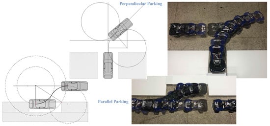
This study proposed unified geometric path plans composed of two stages to automatically perform perpendicular and the parallel parking with a reverse path in a narrow space. In the perpendicular parking, a simple three-characters parking motion and a five-characters parking motion targeting a narrow parking spot were used. In the five-characters parking motion, it was possible to safely enter a parking spot narrower than the minimum width calculated in the three-characters parking motion. Before executing automatic parking, the minimum width of the possible parking spot was computed, and the surrounding space was considered together to determine the availability of parking and the optimal stage of the path plan. In a similar concept, even in parallel parking, it was possible to determine whether to park by calculating the minimum length of the available parking spot and the number of repetitions of motion before starting the parking operation.
2. Automatic Perpendicular Parking
In this study, reverse automatic parking was considered, and in the case of perpendicular parking, the initial posture of the vehicle was set to be located perpendicular to the parking spot on the right. As in most geometric methods, the possible unit motions of the vehicle in both perpendicular and parallel parking were classified into six types: straight forwards (), straight backwards (), left-steering forwards (), left-steering backwards (), right-steering forwards (), and right-steering backwards (). Here, each motion is expressed as a single character with a superscript that expresses forward and backward. In perpendicular parking, the minimum width of possible parking spot was computed, and the availability of parking was determined by considering the surrounding space.
2.1. Three-Characters Perpendicular Parking
As can be seen in
Figure 1, with a simple reverse perpendicular parking motion, the shortest word
starting with
and ending with
is possible. For such parking, the vehicle passes through the right parking spot vertically separated by
in
motion and goes straight to the appropriate point. Here, since the parking spot is located on the right side of the vehicle, it turns to the right while moving backwards until the vehicle is aligned with the parking spot in a straight line by
motion. Finally, the parking is ended by continuing to enter the parking spot with a straight backwards
motion. In
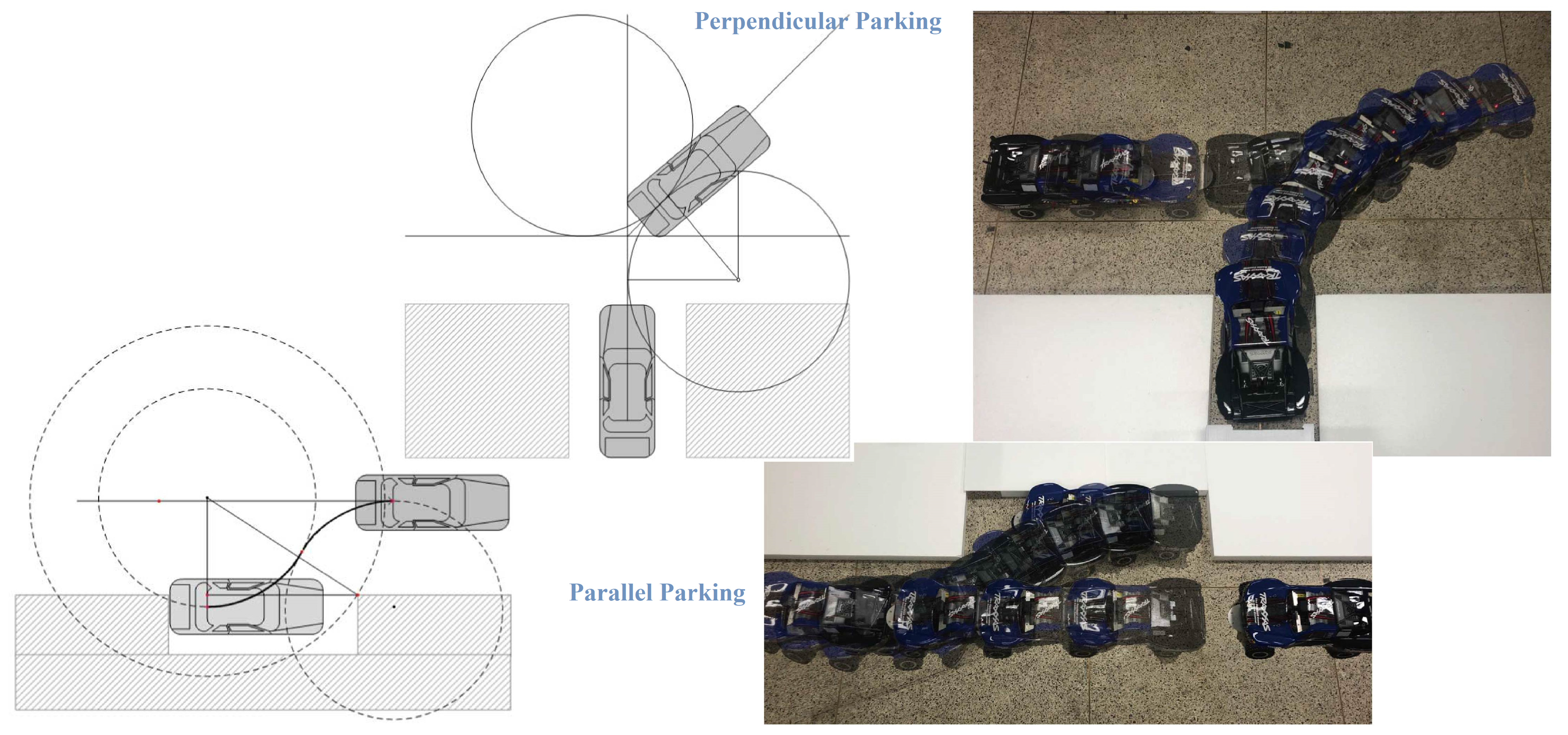
Figure 1, the dimensions related to vehicles are shown in lowercase letters, and the dimensions related to parking spaces are shown in capital letters.
Considering the Ackermann steering, when the center of the rear axle of the vehicle is
, the turning radius
related to the
motion becomes Equation (1). In Equation (1),
is the vehicle wheelbase and
is the steering angle.
The lengths from the turning center
of the
motion to the front and rear corners
A and
B on the driver’s side and the rear wheel
C on the passenger’s side of the vehicle can be obtained as Equations (2)–(4), respectively. In these equations,
is the overall width of the vehicle.
As can be seen in
Figure 1, the start of the
motion is when the center of the rear axle of the vehicle reaches the point that has progressed as much as
(
) from the center line of the parking spot. In this parking method, the minimum width
of the parking spot is determined in different ways depending on the relative lengths of
and
. First, if
is greater than the sum of
and the rear overhang
, and second,
is less than the sum of
and
, but is still greater than
. In addition, in the third case,
is smaller than
, which is the situation shown in
Figure 1. In this case, the sign of the offset
of the center of rotation
is changed.
2.1.1.
As shown in Equation (5), the offset
is larger than the vehicle’s rear overhang, and the turning center
is in the passageway and its value becomes negative. Therefore, before entering the parking spot, linear alignment with the parking spot is already possible, so the minimum width
of the parking spot becomes the overall width
of the vehicle as in Equation (6).
2.1.2.
The offset
is expressed by Equation (7), and linear alignment is possible after the vehicle enters the parking spot. The minimum width of the parking spot that can be parked without collision with the rear-end point A of the driver’s seat and the corner of the parking spot can be obtained as Equation (8). The width of the parking spot represented by Equation (8) becomes larger than the overall width of the vehicle
.
2.1.3.
As shown in
Figure 1, if
is less than
, point
C of the vehicle and the corner of the parking spot may collide. The minimum width of the parking spot that can be parked without such collision can be obtained by Equation (9).
On the other hand, in the situation of the initial separation
with the given parking spot, the minimum surrounding space for three-characters (
) perpendicular parking can be expressed as
and
values as shown in
Figure 1. The horizontal length
and the vertical length
, which mean the size of the surrounding space, can be obtained by Equation (10), where
is the vehicle’s front overhang.
2.2. Five-Characters Perpendicular Parking
If the width of the parking spot in the above-described three-letter perpendicular parking is narrower than the calculated minimum value, it may collide with the parking spot boundary during motion. In this case, it is necessary to increase the entry direction angle of the vehicle before the motion, such as the method used in manual parking, so that safe entry to the parking spot is possible. The direction just before motion in three-character parking is parallel to the parking spot, so the direction angle is 0°. Therefore, if the and motions are added before the motion to increase θ, it is possible to safely enter the parking spot narrower than the minimum width calculated in the three-character perpendicular parking. This five-character parking route is configured differently depending on the value of resulting from the added motion. The range of possible in this study was set to 0° to 90°, and the configuration of the parking path changes based on 45° and 90°. On the other hand, it should be noted that in five-character parking, as the direction angle increases, the surrounding space increases. Therefore, to minimize the surrounding space required for parking, it is necessary to set the direction angle as small as possible.
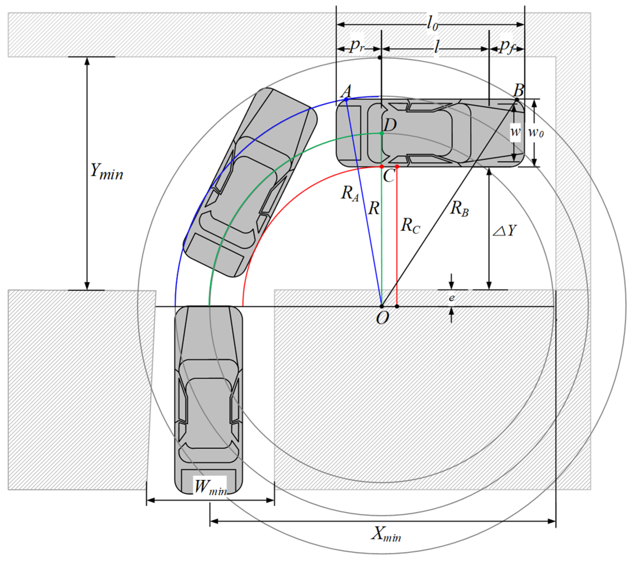
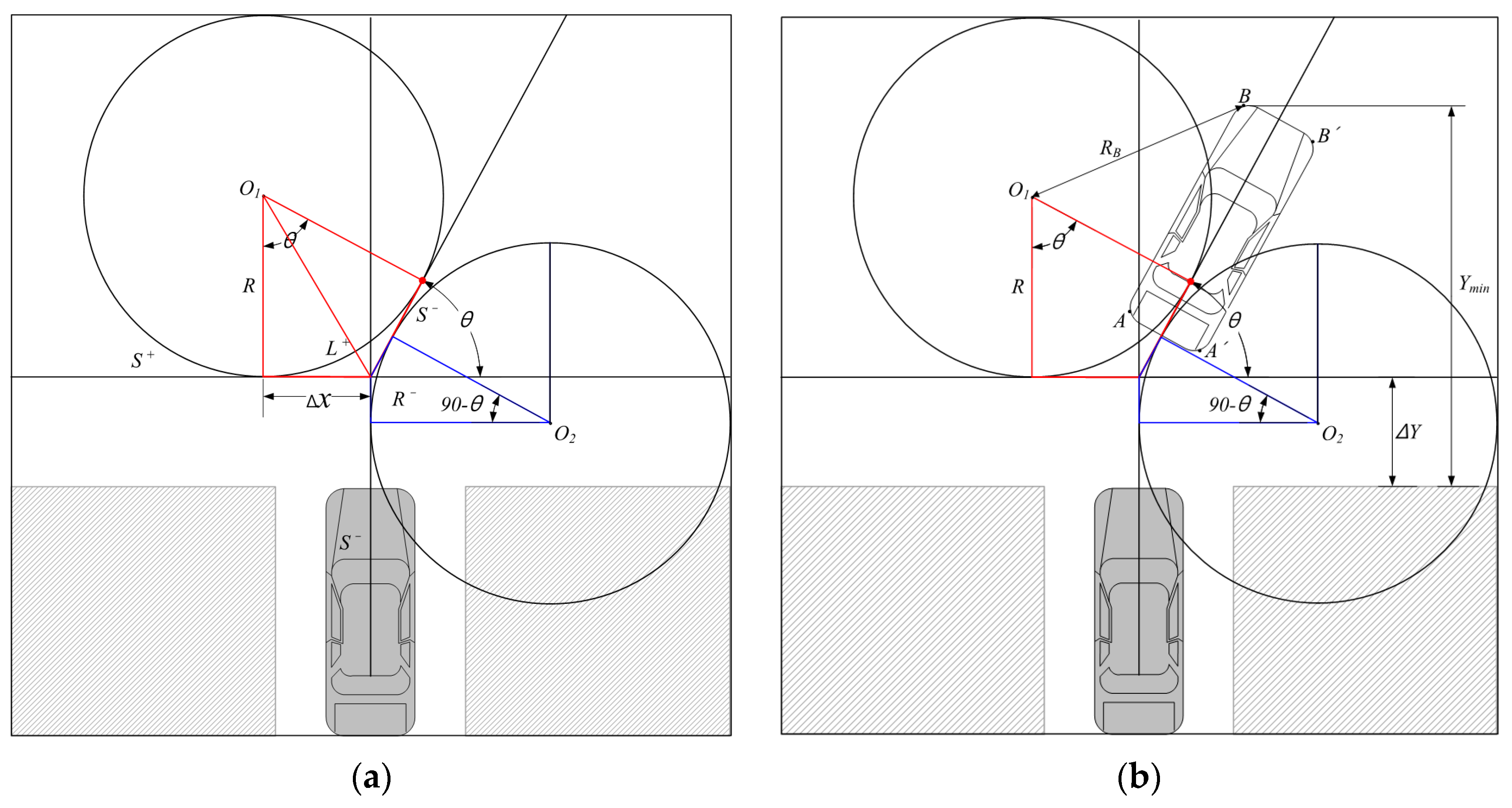
2.2.1. Angle between 0° < θ < 45°
Increasing
from 0° until it reaches 45°, a five-character parking path of
is formed as shown in
Figure 2a. The vehicle proceeds straight ahead (
) from the center line of the parking spot to a point separated by
. Here, the vehicle starts
motion, turns
, and then performs
motion. The straight distance
to the starting point of the
motion is given by Equation (11).
On the other hand, for the surrounding space,
can be obtained from
Figure 2b as shown in Equation (12).
where
Here, when becomes 45°, the straight distance to the start point of motion becomes 0, and motion disappears. That is, a four-character parking path of is formed, and the number of steering movements is reduced, reducing the parking time.
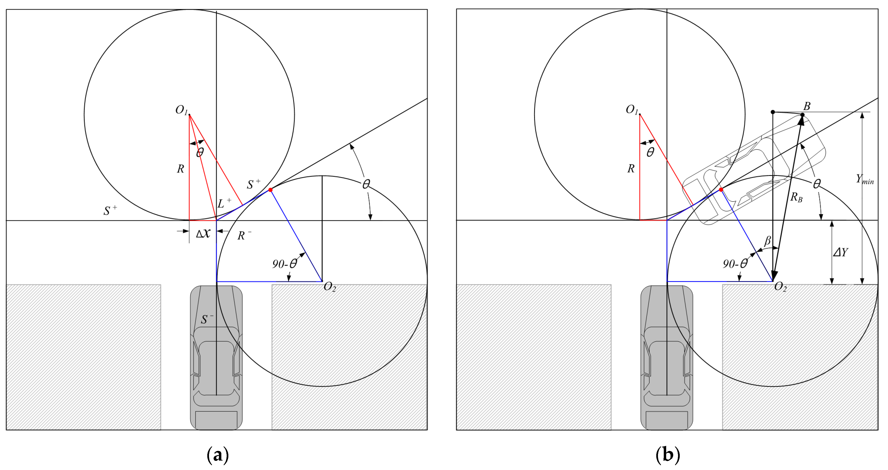
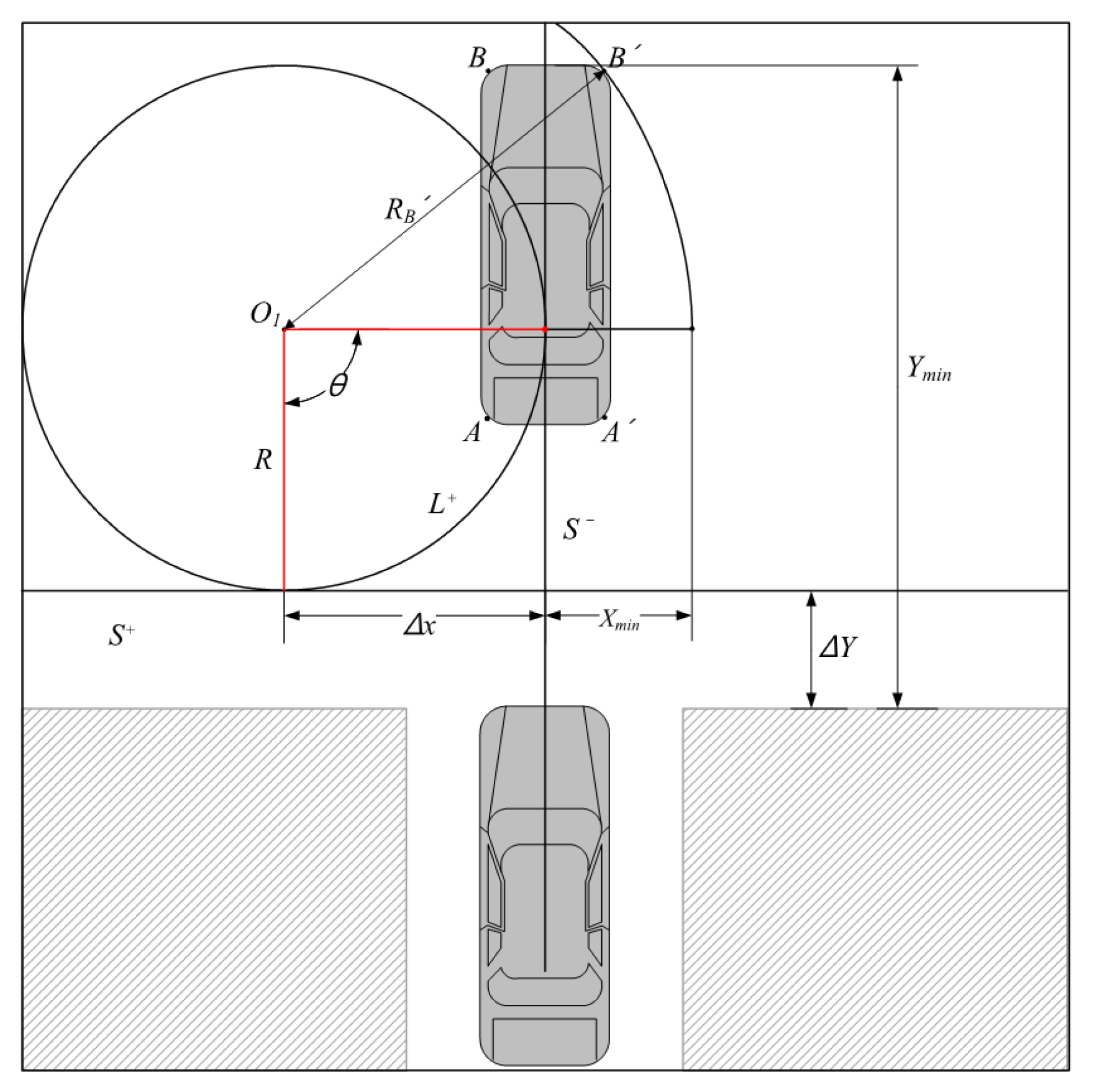
2.2.2. Angle between 45° < θ ≤ 90°
As shown in
Figure 3a, a reverse motion rather than a forward motion is required at the end point of
, and a five-character parking path of
is formed. The vehicle proceeds straight ahead (
), then starts the
motion at a point
from the center line of the parking spot and turns
, and then moves backwards with
motion. At this time, the reversing distance
to the starting point of
motion is the same as the value of Equation (11), but the sign is changed, and it is expressed as Equation (13).
On the other hand, for the surrounding space,
can be obtained from
Figure 3b as shown in Equation (14).
where
As shown in
Figure 4, when
reaches 90°, the vehicle proceeds straight ahead (
) and then starts
motion at a point that is
away from the center line of the parking spot and turns
. Then, the following two motions are extinguished and the
motion is complete, and a three-character parking path of
is formed. This three-character parking is simple and clear, so the parking time and effort can be shortened, but a lot of surrounding space is required. As shown in
Figure 4, when
reaches 90°, the surrounding space
required for parking can be obtained by Equation (15).
3. Automatic Parallel Parking
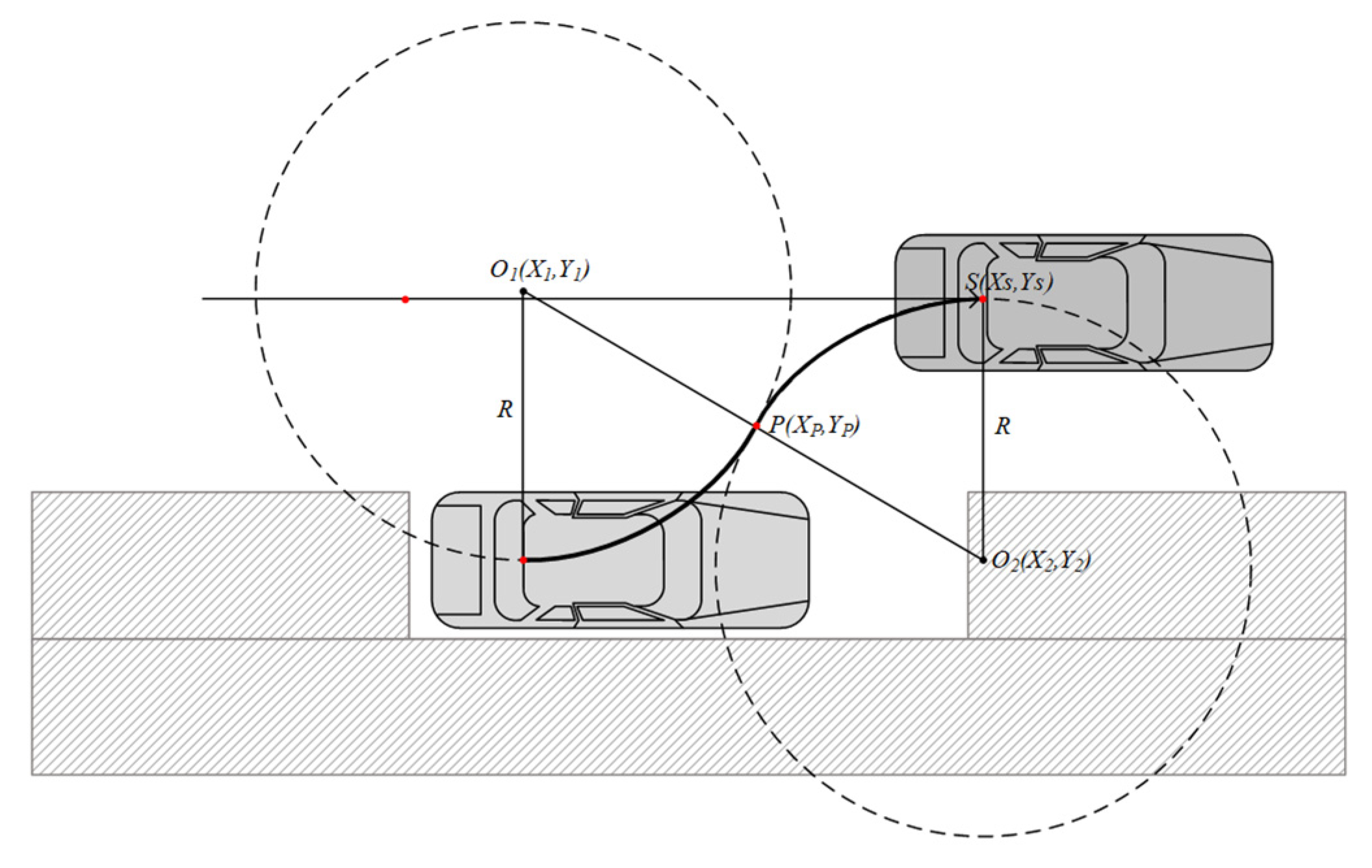
Like perpendicular parking, reverse automatic parking is considered in parallel parking, and the initial posture of the vehicle is set to be positioned parallel to the parking spot on the right. If the length of the parking spot is long enough, it is possible to park comfortably forward, but it is effective to park backward in short parking spots for parallel parking located on the side of the road. In addition, parallel parking is usually attempted on the side of a road with traffic, so unlike perpendicular parking, it is very important to use the surrounding space to a minimum. The unit motion of the vehicle is divided into six characters (motions) as in perpendicular parking. In parallel parking, it is possible to determine whether to park by calculating the minimum length of the required parking spot and the number of repetitions of the parking operation.
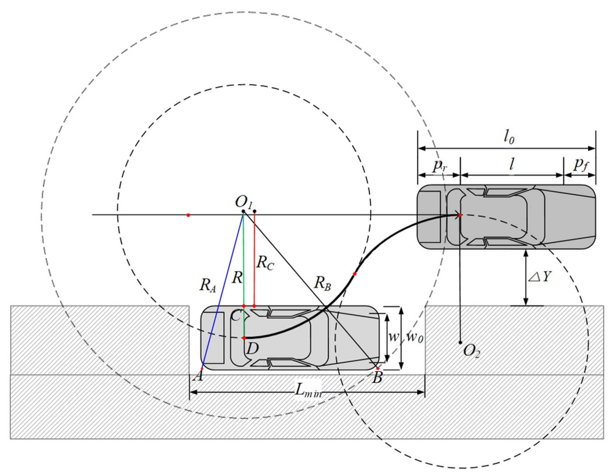
3.1. Three-Characters Parallel Parking
As can be seen in
Figure 5, the shortest word
can be inferred for a simple reverse parallel parking. For such parking, the vehicle passes through the right parking space vertically separated by
with
motion and goes straight to the appropriate point. Here, since the parking spot is located parallel to the right side of the vehicle, the parking can be completed with continuous movements of
. However, in reality, the parking can be completed at an appropriate location within the parking spot by adding an
motion at the end.
In the reverse parallel parking shown in
Figure 5, the vehicle moves to the appropriate point in parallel to the parking spot with
motion. Here, since the parking spot is located on the right side of the vehicle, it moves backward with the
motion, stops at the contact point of the two (steering) circles, and then executes the
motion. The minimum length of the parking spot for the vehicle to completely enter is the distance from the point where the large left circle meets the front edge of the parking spot to the point
C, plus the rear overhang
, and is expressed by Equation (16).
and
are the values shown in Equations (3) and (4).
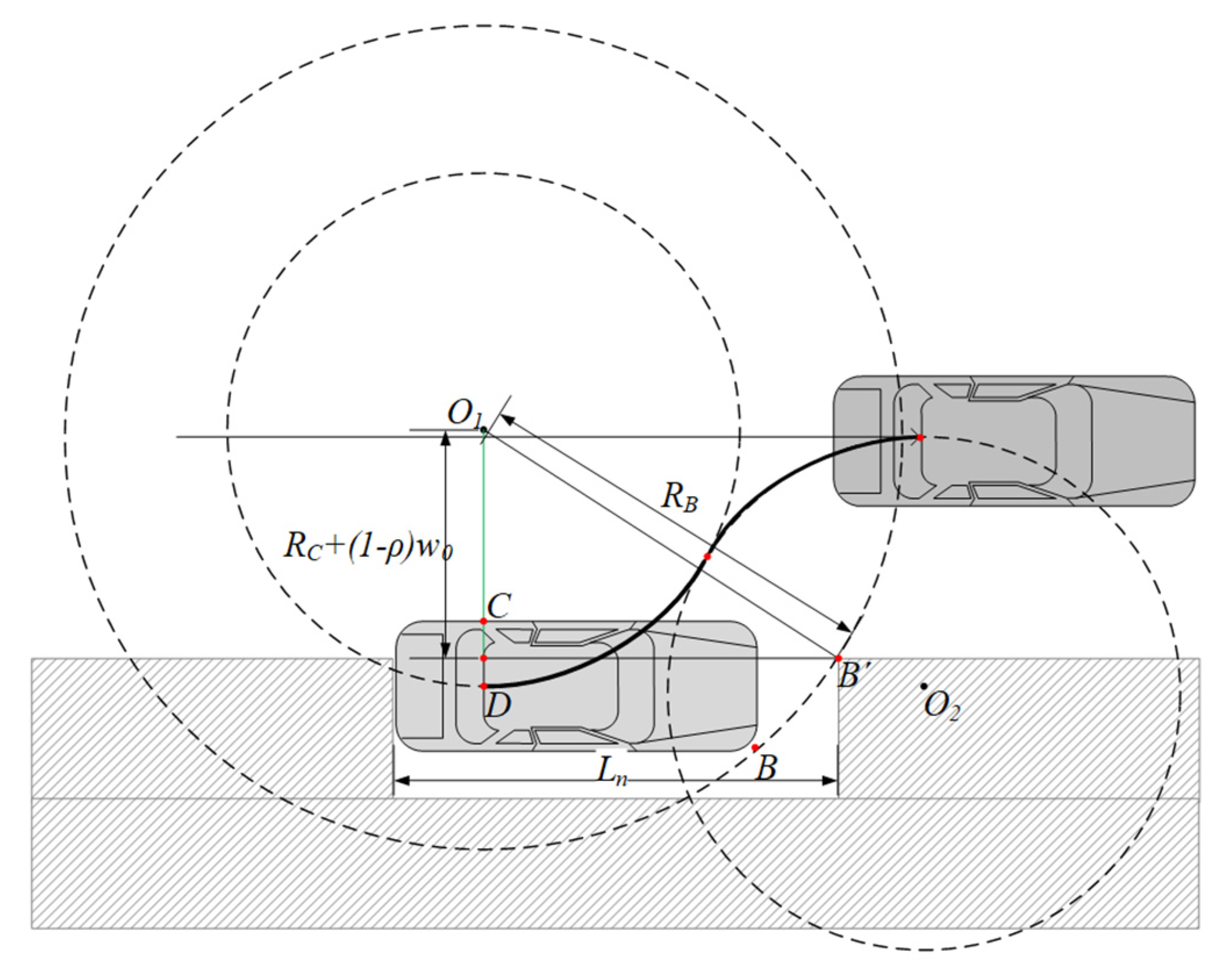
However, if the length
of the parking spot is longer than the vehicle length
but is less than
shown in Equation (16), full parking is impossible. However, as shown in
Figure 6, partial parking where the part (width) of the vehicle is exposed outside the parking spot is possible. If the vehicle width ratio
that enters the parking spot, it is set to full parking, and if it is less than 1, it is set to partial parking. Here, it is assumed that the depth of the parking spot is the same as the overall width of the vehicle
. Then, the minimum length of the parking spot corresponding to the vehicle width ratio
value entering the parking spot can be obtained by Equation (17).
In Equation (17), if , it becomes full parking and becomes equal to Equation (16).
On the other hand, as can be seen in
Figure 7, the starting point of the
motion is the point where the vehicle proceeds (
motion) by a distance of
from the center of the left circle. When the center of the left circle is the origin, the starting point
P of the
motion can be expressed by Equation (18).
Here, if the vehicle width ratio value entering the parking spot is less than 1 for partial parking, the starting point moves upward by the exposure amount .
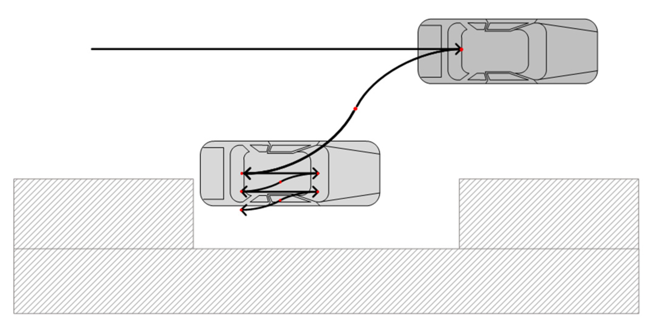
3.2. Repetitive Three-Characters Parallel Parking
In the three-characters (
) partial parallel parking, if the length
of the parking spot is longer than the overall length of the vehicle
, full parking is possible by repeating the three characters (
Figure 8).
Figure 9 shows the dimensions to specifically explain these repetitive motions. For a repeated parking operation, the vehicle goes straight (
) as much as the maximum length
in the parking spot, and then steers to the right and back (
) for
to further enter the parking spot. In addition, for the rest of
, it steers to the left and back (
), making it parallel to the parking spot.
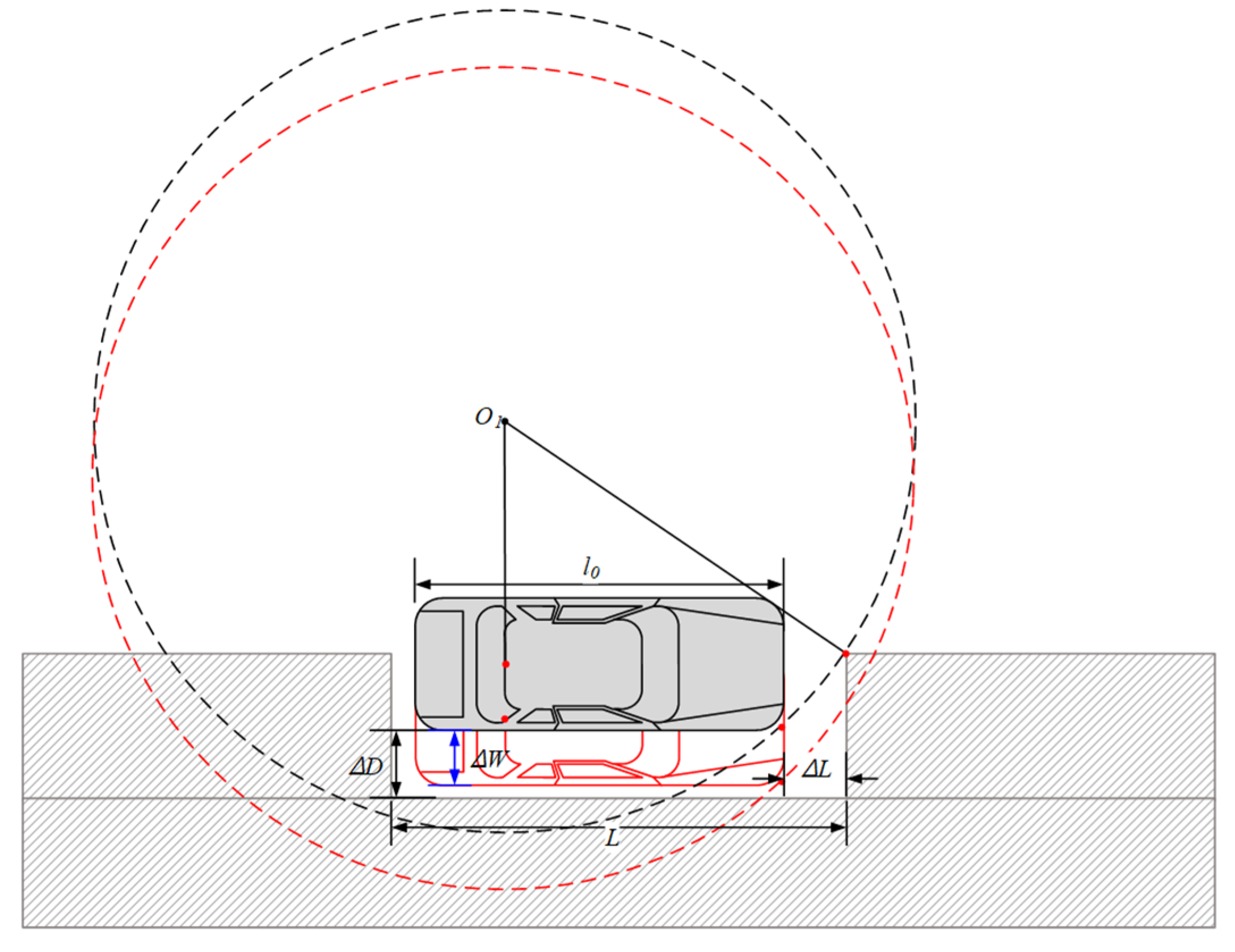
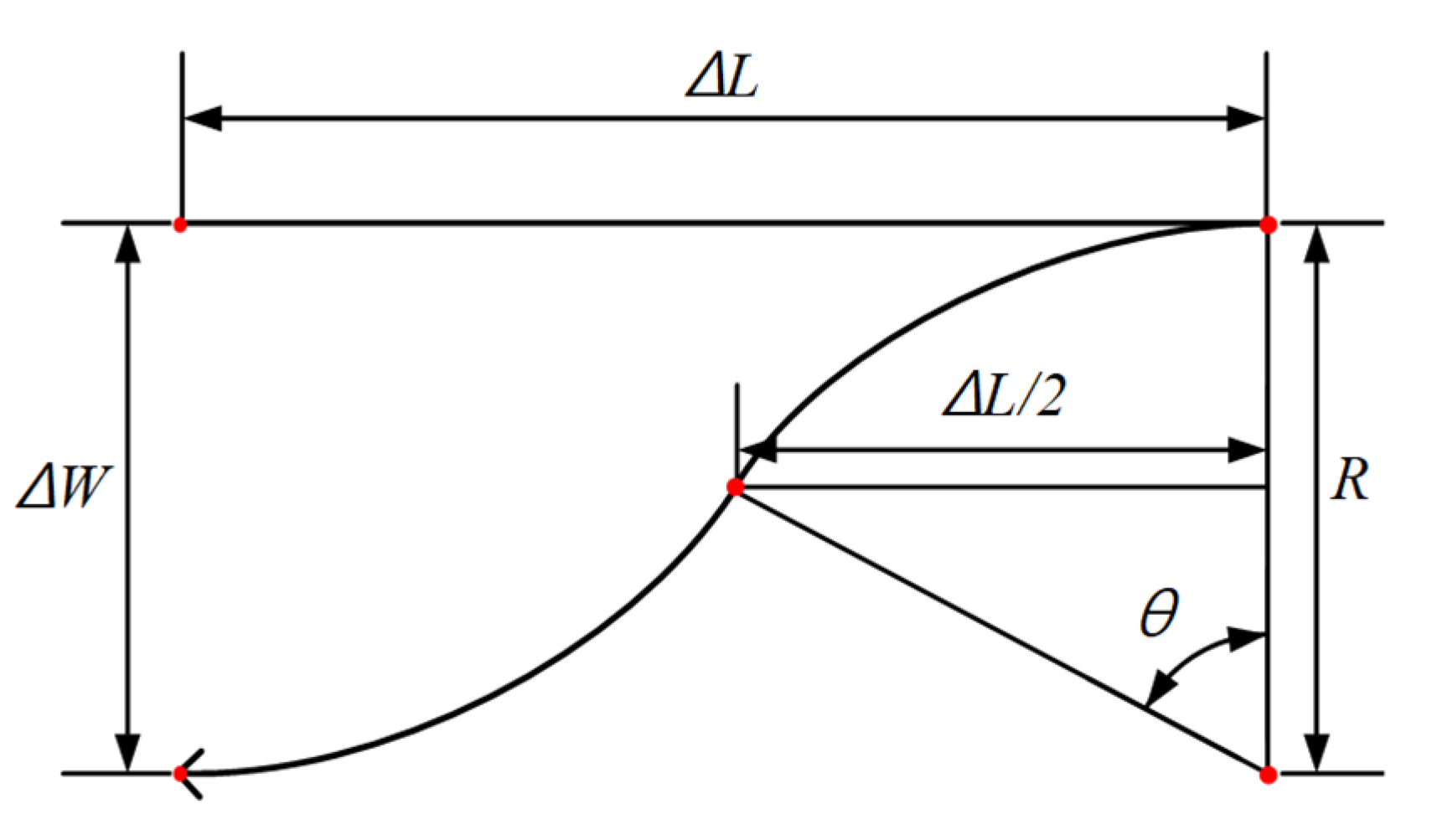
To perform the effective repetition (
) motion within the parking spot, it is necessary to limit the number of repetitions, and it is generally considered that two to three times are appropriate when considering traffic conditions. As can be seen in
Figure 10, the exposure width
of the vehicle, which is reduced by one additional (
) motion, can be obtained by Equation (19).
In Equation (19),
is expressed as Equation (20) from the turning radius
and the lengthwise clearance
inside the parking spot.
On the other hand, the number of repetitions of the additional (
) motion required until full parking (
) can be calculated by Equation (21) as shown in
Figure 9.
In Equation (21),
is the length of the vehicle width exposed outside the parking spot and is expressed as Equation (22).
4. Experimental Tests of Automatic Parking
The perpendicular and parallel automatic parking path planning was implemented through an autonomous model car experiment. The autonomous model car [
18] used in this study used a BLDC motor with a PWM control method, and the main dimensions are summarized in
Table 1. The Xycar-A3 model was equipped with an NVIDIA TX2 processor, LIDAR, camera, inertial sensor, and motor controller. This model used the Robot OS (ROS) platform, which is a device control middleware applied to real vehicles.
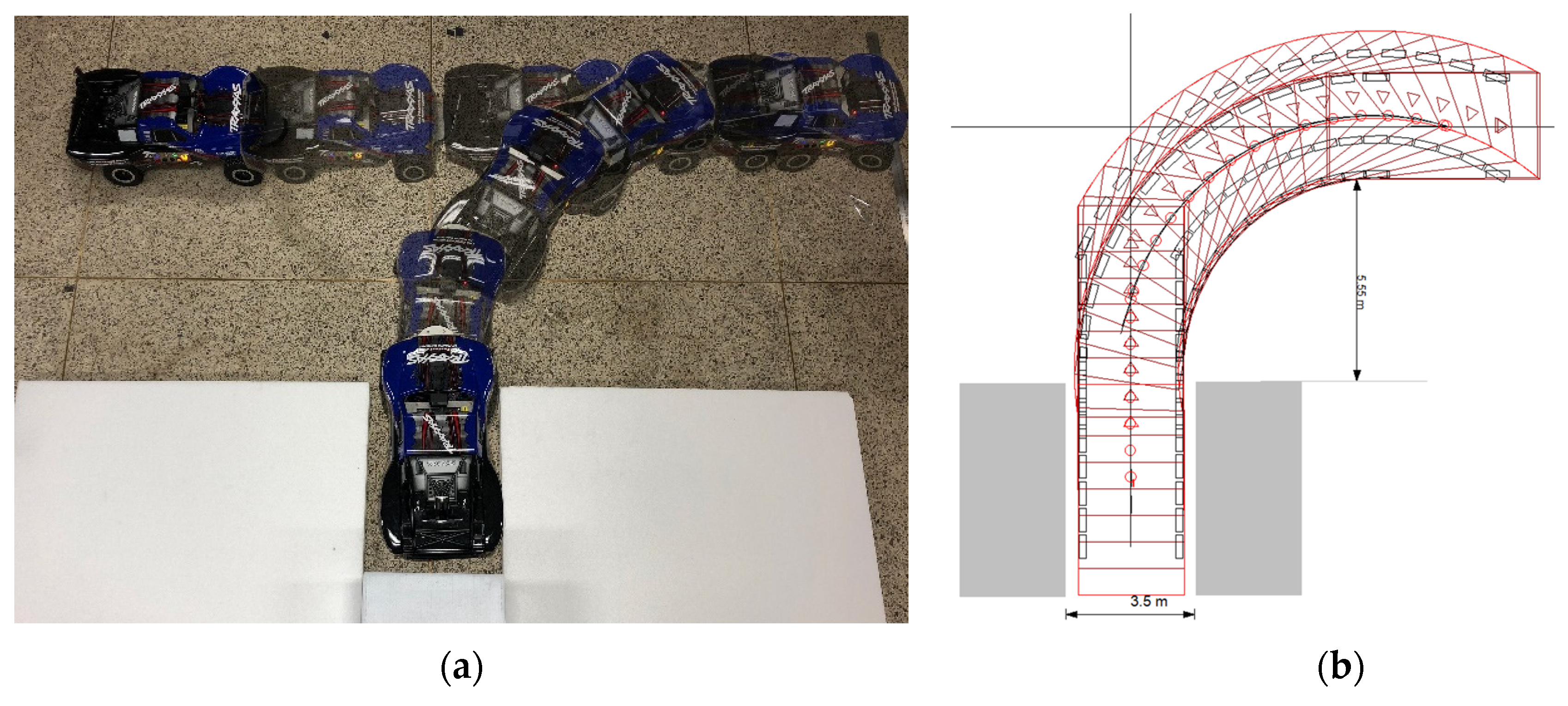
4.1. Perpendicular Parking Tests
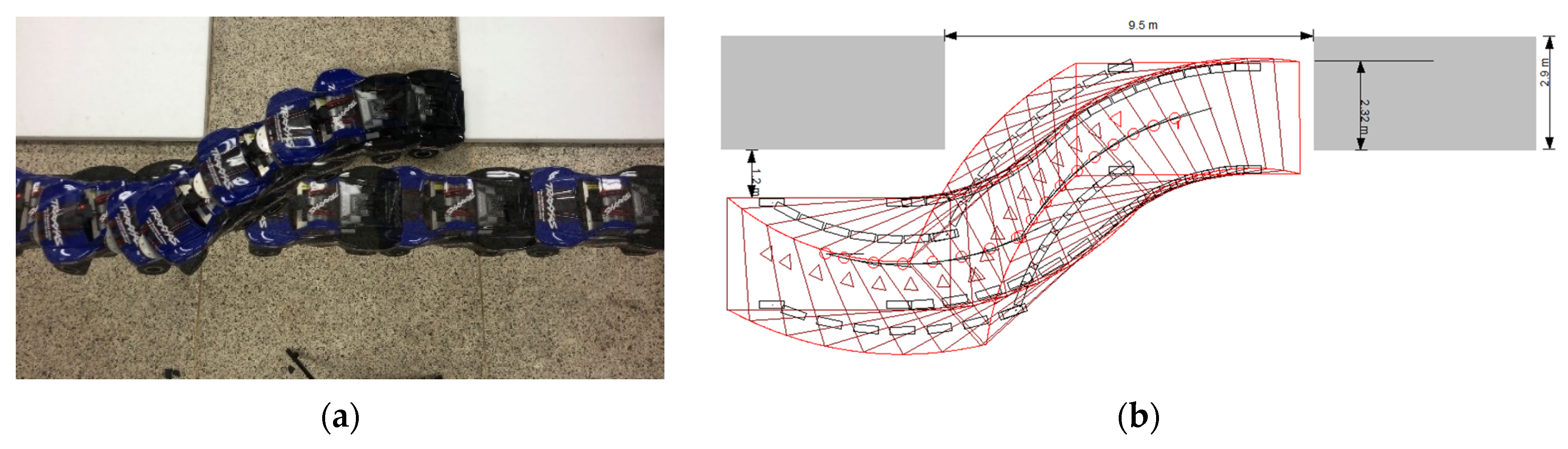
Figure 11 shows the results of a successful three-characters (
) perpendicular parking operation. The separation distance from the entrance of the parking spot was set as
, and the offset of the center of curvature
, resulting in a situation as shown in
Figure 1. Therefore, the minimum width of the parking spot
can be obtained from Equation (9), and the width of the parking spot must be greater than this to enable
perpendicular parking.
Figure 11 shows the successful parking scene of the car with an overall width of 290 mm in a cramped space with a width of
and the trajectory simulated by the PC-Crash program [
19]. PC-Crash is widely used as a specialized program for traffic accident analysis.
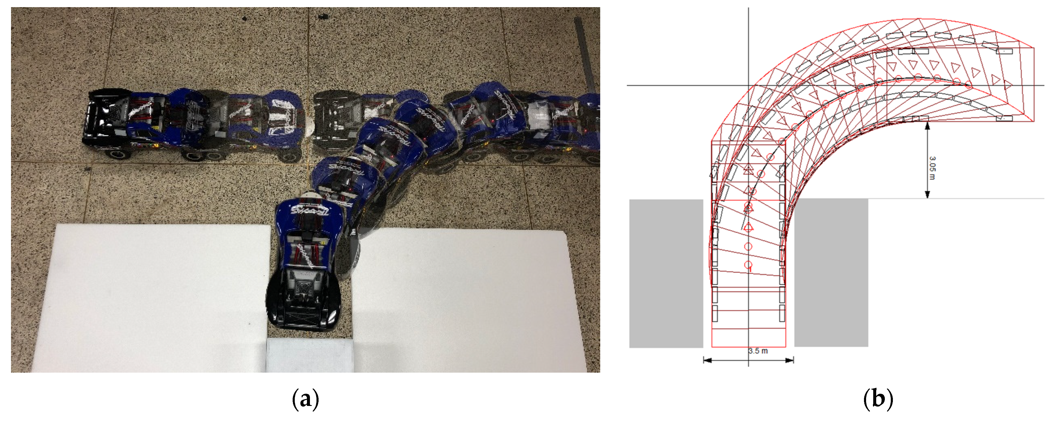
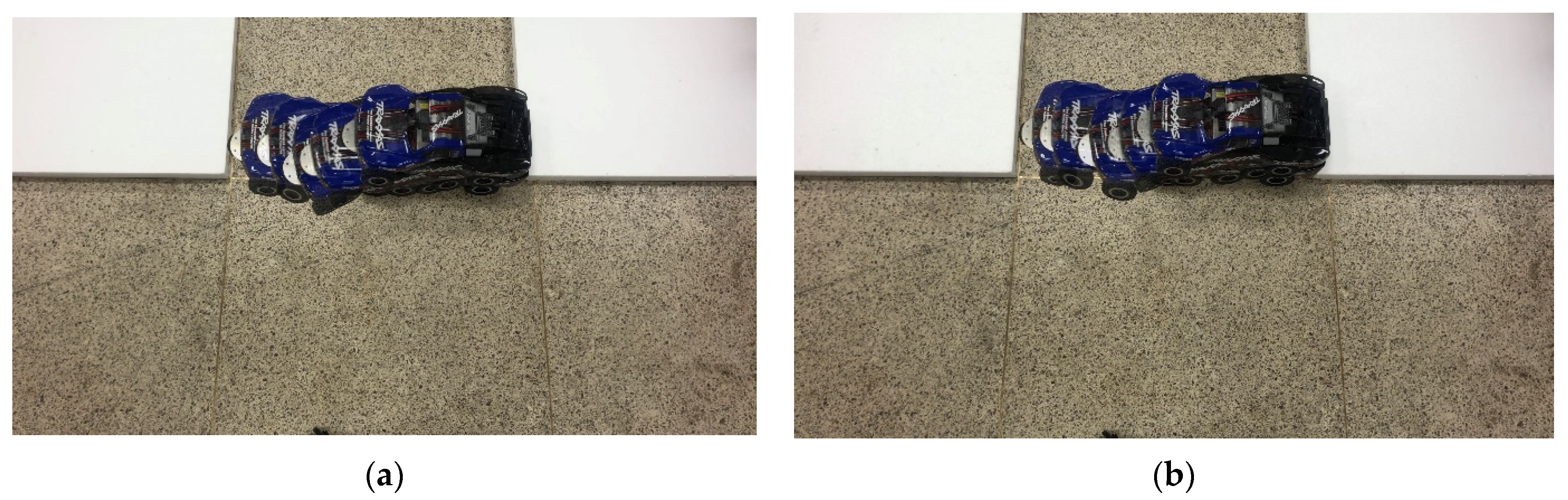
In
Figure 12, the width of the parking spot was 350 mm, which was the same as
Figure 11, but the separation distance
was reduced to 305 mm. The curvature center offset
shown in
Figure 1 became larger than the width of the parking spot given by the minimum parking spot width
from Equation (9). Therefore,
perpendicular parking was not possible, and a collision occurred near the right entrance corner of the parking spot as seen from
Figure 12.
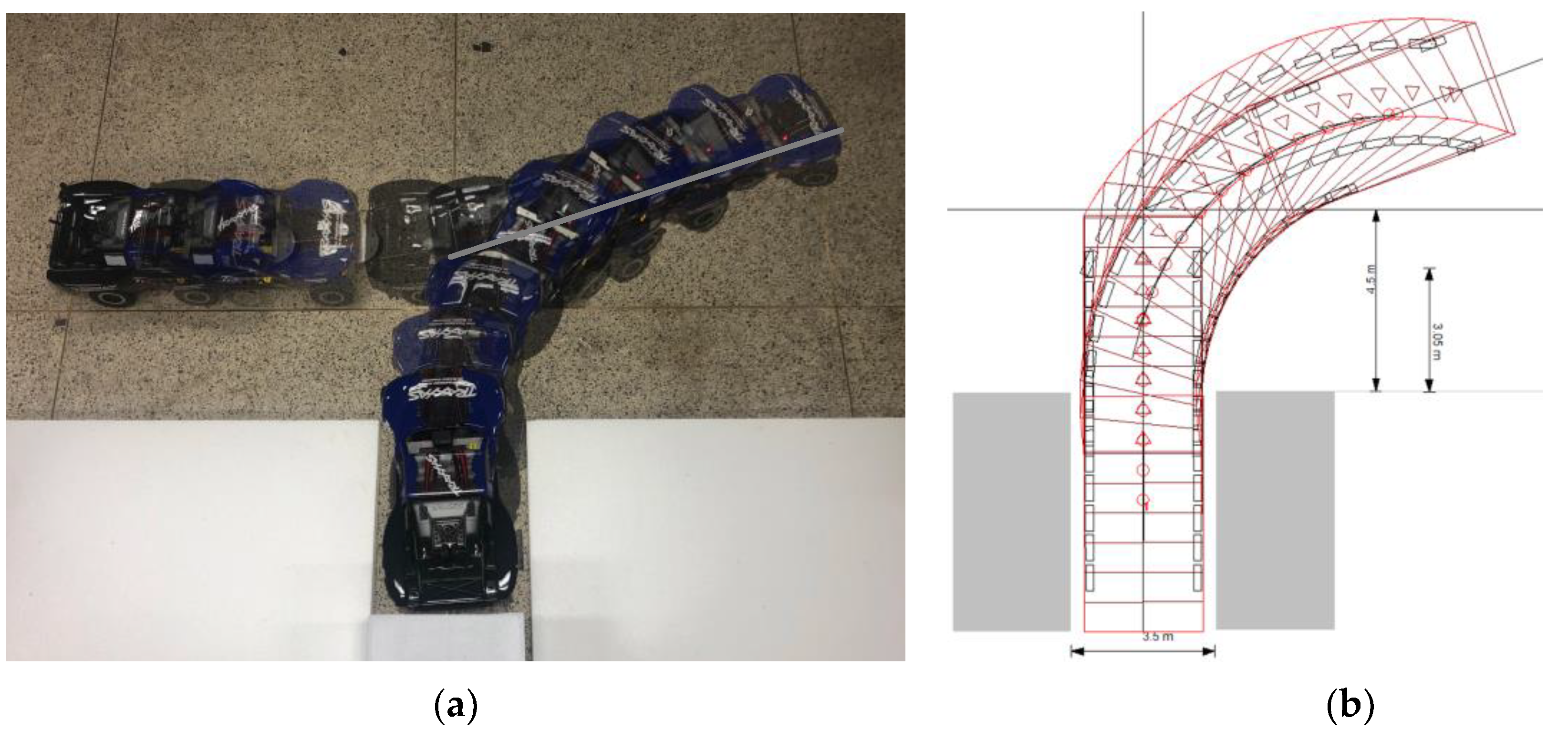
To enable parking in such a situation (
), as shown in
Figure 13, a five-characters parking (
) path plan was used. If the direction angle
is increased from
by adding
and
motion before the
motion of the three-characters perpendicular parking, safe entry to the parking spot is possible when the width of the parking spot is larger than the overall width of the car and the sufficient surrounding space can be secured. If the direction angle
is increased from 0° in a similar way to Kim [
10], the minimum value of
that can be parked without collision with the parking spot boundary can be obtained as approximately 20°.
Figure 13 shows the results of an automated parking experiment that failed with three-characters parking but succeeded with five-characters parking. However, it required a wider surrounding space in the vertical direction than the three-characters perpendicular parking.
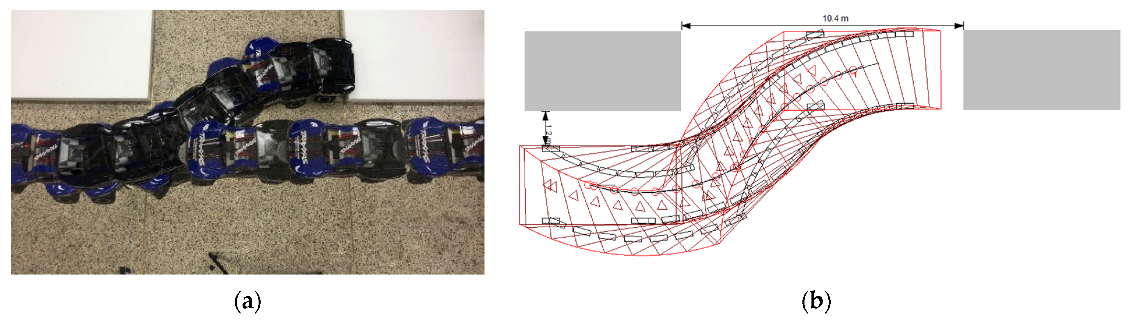
4.2. Parallel Parking Tests
Figure 14 shows the results of the successful experiment of three-characters (
) parallel parking. The vertical separation distance from the parking spot was set relatively short as
, and the depth of the parking spot was
, which was the same as the overall width of the car. Since parallel parking should be carried out on the side of the road where there is usually traffic, it is important to minimize the surrounding space. From Equation (16), the minimum length
of the parking spot for full parking (
) at one time can be obtained, and the length of the parking spot must be larger than this to enable three-characters parallel parking.
Figure 14 shows the scene of a successful reverse parallel parking experiment in a space with a margin of
less than the theoretical value with the parking spot length
and the trajectory simulated by the PC-Crash program.
If partial parking (
) that allows a 20% exposure width rather than full parking is required, the theoretical minimum length of the required parking spot can be obtained from Equation (17) as
. Here, the test was performed again with the parking spot length
with a margin of 4 mm less than the theoretical value. As can be seen in
Figure 15, about 20% of the car’s overall width (
) was exposed after parking with three characters (
).
On the other hand, using Equation (19), the exposure width
of the car that can be reduced by one additional
motions was approximately 33 mm. Therefore, for full parking without exposure outside the parking spot, two additional
motions were required from Equation (21).
Figure 16 shows each experimental scene in which parking was performed with additional
motions.
5. Conclusions
In this study, two-stage geometric path plans were presented to automatically perform perpendicular and parallel parking as a reverse path in a narrow space. These parking path plans consisted of a combination of six-unit motions (paths) based on arcs and straight lines, and each unit motion was expressed as a single character with a superscript. In this geometric automatic parking path planning, a method to estimate the required size of the parking spot and the surrounding space was also obtained.
In perpendicular parking, a simple three-characters parking motion and a five-characters parking motion targeting a narrow parking spot were used. Before executing automatic parking, the minimum width of the possible parking spot was computed, and the surrounding space was considered together to determine the availability of parking and the optimal stage of the path plan. In parallel parking, a simple three-characters parking and a repetitive three-characters parking motion that can be parked in a tiny spot were presented. Like perpendicular parking, in parallel parking, it was possible to determine whether to park by computing the minimum length of the possible parking spot and the number of repetitions (or exposure width) of the operation before the start of the parking.
The algorithms for the parking spot and the surrounding space proposed in this study for the geometric path planning of perpendicular and parallel parking of a vehicle were validated through model car tests. Considering the parking spot and the surrounding space before starting the parking operation, selecting an appropriate path plan along with the availability of parking will enable efficient automatic parking.


