Article

Autonomous Human-Vehicle Leader-Follower Control Using Deep-Learning-Driven Gesture Recognition

Department of Mathematics and Computer Science, Lawrence Technological University, Southfield, MI 48075, USA
*
Author to whom correspondence should be addressed.
Vehicles 2022, 4(1), 243-258; https://doi.org/10.3390/vehicles4010016
Submission received: 15 January 2022 / Revised: 17 February 2022 / Accepted: 1 March 2022 / Published: 9 March 2022
(This article belongs to the Special Issue Driver-Vehicle Automation Collaboration)

Abstract

:
Leader-follower autonomy (LFA) systems have so far only focused on vehicles following other vehicles. Though there have been several decades of research into this topic, there has not yet been any work on human-vehicle leader-follower systems in the known literature. We present a system in which an autonomous vehicle—our ACTor 1 platform—can follow a human leader who controls the vehicle through hand-and-body gestures. We successfully developed a modular pipeline that uses artificial intelligence/deep learning to recognize hand-and-body gestures from a user in view of the vehicle’s camera and translate those gestures into physical action by the vehicle. We demonstrate our work using our ACTor 1 platform, a modified Polaris Gem 2. Results show that our modular pipeline design reliably recognizes human body language and translates the body language into LFA commands in real time. This work has numerous applications such as material transport in industrial contexts.

1. Introduction

1.1. Leader-Follower Background

Leader-follower autonomy (LFA) systems, whereby one or more autonomous vehicles can follow other vehicles without the need for a human operator, is a field that has seen continuous development over the last several decades. Studies of LFA systems include the development of mathematical models [1,2,3,4,5], testing in simulations [1,2,3,4,5,6,7,8], and live experiments [4,5,6,8,9,10] with both two-robot and multi-robot systems. Demonstrations of LFA systems have been conducted with real applications in mind on land, air, and sea [6,10]. The use of neural networks has also been introduced as a substitute for traditional mathematical pathfinding [9].
Despite the work done in vehicle-vehicle (VV) systems, academic LFA development has largely ignored human-vehicle (HV) systems on large-scale autonomous vehicles. Though there have been studies on human-robot following [11,12] as well as application in the commercial sector [13], these studies are more concerned with personal interactions with smaller robots rather than work with medium or large-sized vehicles.

1.2. Gesture Recognition Background

Gesture recognition (GR) problems require a system to classify different hand and body gestures. Like LFA systems, GR is not a new problem and has been researched for several decades. In 1991, Murakami and Taguchi developed a neural-network based solution to classify words in Japanese sign language based on time-series context and positional values indicating the fingers’ configuration and the hand’s orientation [14]. More recent solutions are based on convolutional neural networks (CNNs), a machine-learning mechanism commonly used for image recognition tasks. Recent studies often suggest a combination of CNNs and other neural network structures to accomplish GR tasks [15,16,17,18]. Some studies even make use of biological sensor data [16], and others have developed solutions based on pose estimation data, whereby an image is converted into a set of values representing the position of certain parts of the hand or body [17].

1.3. Previous and Novel Work

We have already demonstrated that practical and reliable autonomous human-vehicle leader-follower behavior is possible [19] using our test vehicle, known as ACTor 1 (Autonomous Campus Transport 1, Figure 1). The ACTor is a Polaris Gem 2 modified with sensory capability, including a LIDAR and several cameras, and computer control through a DataSpeed drive-by-wire (DBW) system. We use the Robot Operating System (ROS) to program interactions between the vehicle, its sensors, and user commands [20,21]. ROS is a software platform that abstracts the program-level control of the vehicle’s hardware for standardization. An engineer can integrate ROS-compatible hardware into their control program without needing to know that hardware’s proprietary control architecture [22]. The previous demonstration used traditional computer vision processing to identify ArUco markers, a type of fiducial marker similar to QR codes that are optimized for reliable recognition and location in varied circumstances, and associate them with a human “leader” [19,23]. Object and human detection was accomplished with the YOLOv3 object detection system [24]. The human leader can then walk around, and ACTor 1 will follow them until either the follow function is disabled or the human leader walks out of camera view.
In this study, we demonstrate the practical application of deep-learning based gesture recognition as a control mechanism for human-vehicle LFA as a more natural and versatile alternative to traditional fiducial markers. We also demonstrate that gesture recognition can be used to control a vehicle in a real-world scenario. This is the first time that human-vehicle LFA has been demonstrated on large-scale vehicles in the known literature. We envision several useful applications for such HV systems beyond automobile control, such as material transport in loading bays, construction sites, and factory floors.
In Section 2 we begin by explaining the fundamentals of neural networks, the gestures chosen for control, and our gesture recognition system. We continue by introducing the ACTor 1 platform, briefly outlining the basic principles of ROS and explaining our ROS program architecture and implementation on ACTor 1 in Section 3. In Section 4 we describe our live demonstrations and their results. Finally, in Section 5, we discuss our results and avenues of future study.

2. Gesture Recognition

2.1. Neural Network Fundamentals

Artificial neural networks (NNs) are algorithmic structures designed to perform machine learning, whereby a computer program can be “trained” on a dataset in order to “learn” to make useful predictions. Neural networks are made up of layers of logically connected nodes called neurons. A densely-connected neural network (DNN) has an initial layer of input neurons, which represent the input data, a final layer of output neurons, which represent the result of processing, and layers of hidden neurons in between, where processing occurs. The final result of processing is called a prediction.
Each connection is associated with a weight value. Each layer also is given a bias value. During processing, each sample vector is multiplied by the matrix of weights, to which the biases are added, and an activation function is applied. The activation function is used to constrain the output values as they propagate through the network, which prevents highly unbalanced results. This is then passed to the next layer. Choosing the correct activation function depends on the problem at hand, but in our system (see Section 2.3.2), we use rectified linear units (ReLu) ( f ( x ) = max ( x , 0 ) ) for our hidden layers. In this project, we have a multiclass classification problem, and thus make use of a softmax function for the output layer, which returns a probability distribution for each class.
The network “learns” using a dataset consisting of input samples and the corresponding expected output. The network iterates over the dataset and makes a prediction for each sample or batch of samples. These predictions are then compared to the target output, and the difference between the prediction and target output are measured as a loss value. We use categorical cross entropy as our loss metric [25]. The error values are then passed backwards through the network using the back propagation technique, which adjusts each weight value to produce results closer to the correct output. These iterations are then repeated for a number of epochs, which is predetermined by the programmer. The designer may also arrange for a subset of the input data to act as validation during training. In-between each epoch, the model is run through the validation dataset to test its effectiveness on unseen data, and the validation loss and accuracy are reported. During the training stage, the engineer’s goal is to minimize validation loss. Otherwise, overfitting may occur, where the model performs too well on the training data, making it less responsive to unseen data.
Once the model is sufficiently trained, it can be evaluated on unseen data samples, and if it works sufficiently, can be deployed for practical use [26,27].

Convolutional Neural Networks
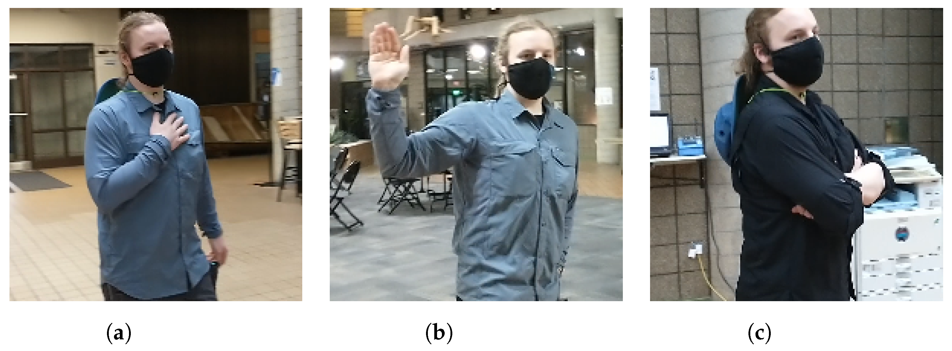
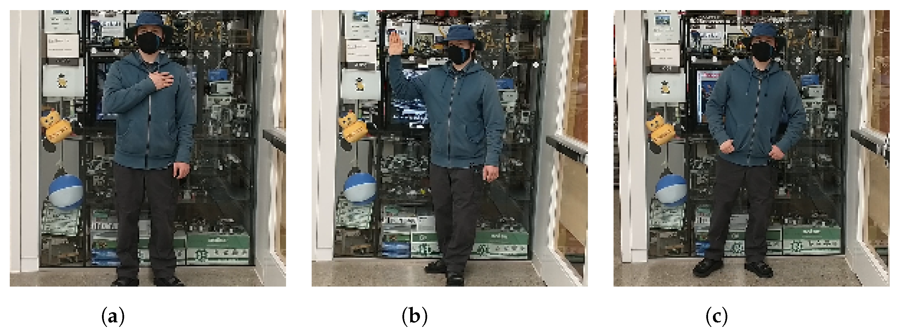
A common application of DNNs for image recognition is the convolutional neural network (CNN), which uses a iterative “matching” algorithm to identify features common to the images in the dataset. This essentially means that the network will learn to recognize abstract features that might be found in the image. For example, a CNN trained for facial recognition might learn the abstract representation of the human nose, eyes, and ears as separate filters rather than try and compare everything in the entire image at once [26].

2.2. Gestures

To control the ACTor, we decided on a set of two gestures, each corresponding to a command. A list of gestures and their corresponding function can be seen in Table 1.
The follow command is indicated by the user putting their hand on their chest. Upon receiving a follow command, the system is instructed to recognize and track the user giving the command (now called the target). The system then maneuvers the ACTor to follow the user, but also works with the ACTor’s LIDAR (see Section 4 for more information of the ACTor’s systems) to remain a safe distance away from the target. Upon receiving a stop command, where the target puts their palm out to the side next to them, the system is instructed to stop following the user. If it detects neither pose, then it will continue behaving as per the previous instruction. Figure 2 depicts author J. Schulte performing each of the three pose cases. (Our dataset is publicly available here: https://www.kaggle.com/dashlambda/ltu-actor-gesture-training-images (accessed on 28 February 2022). We ask that you cite this paper if you intend to use the images for any purpose. It includes 1959 follow images, 1789 stop images, and 1795 none images. However, when training, the program selects a random sample of 1789 images from each subset to ensure training balance.

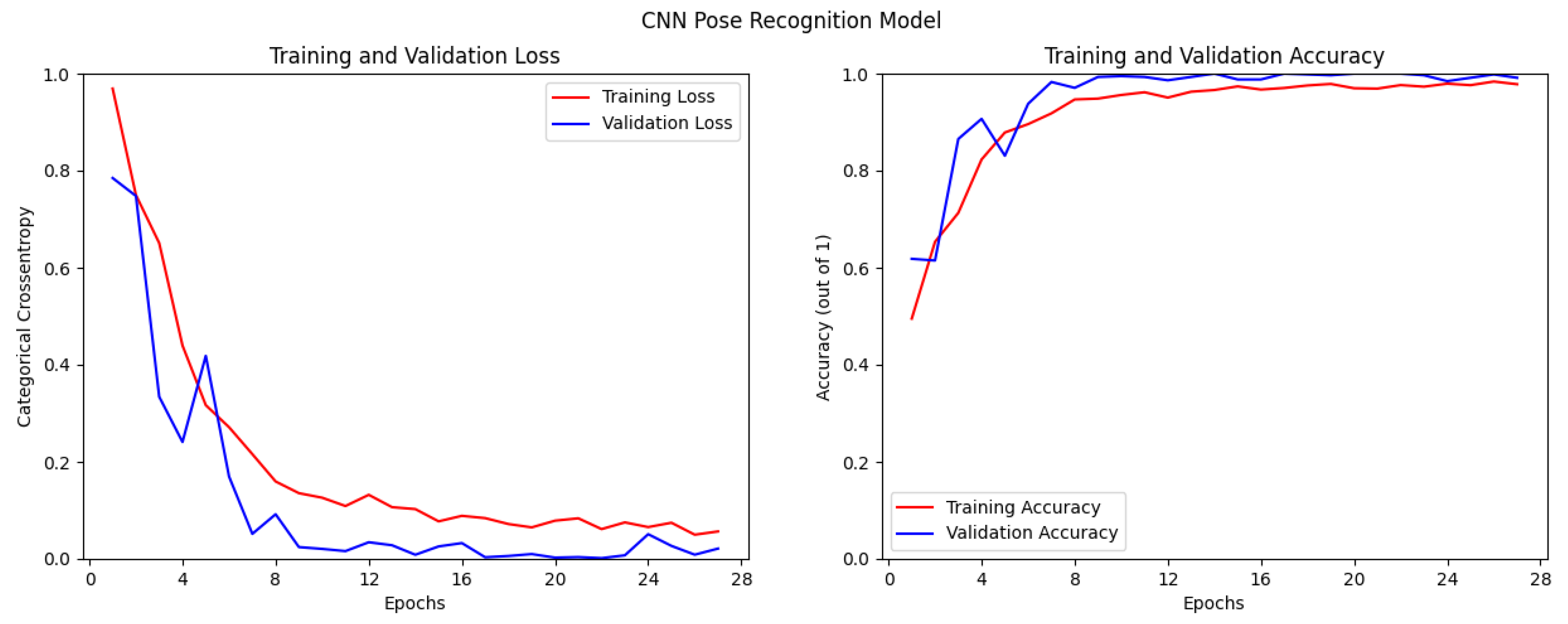
2.3. Neural Network Development

We have developed a pipeline that efficiently translates camera video (structured as a stream of frames) into a command through object detection and pose estimation, but we built a more conventional CNN initially to see if it could be used. In this section, we describe our CNN construction, training, and results, and then explain our final modular pipeline and how it compares with the CNN. Both models were trained and tested on the same datasets, as well as under “lab conditions”, i.e., with our laboratory as a background.

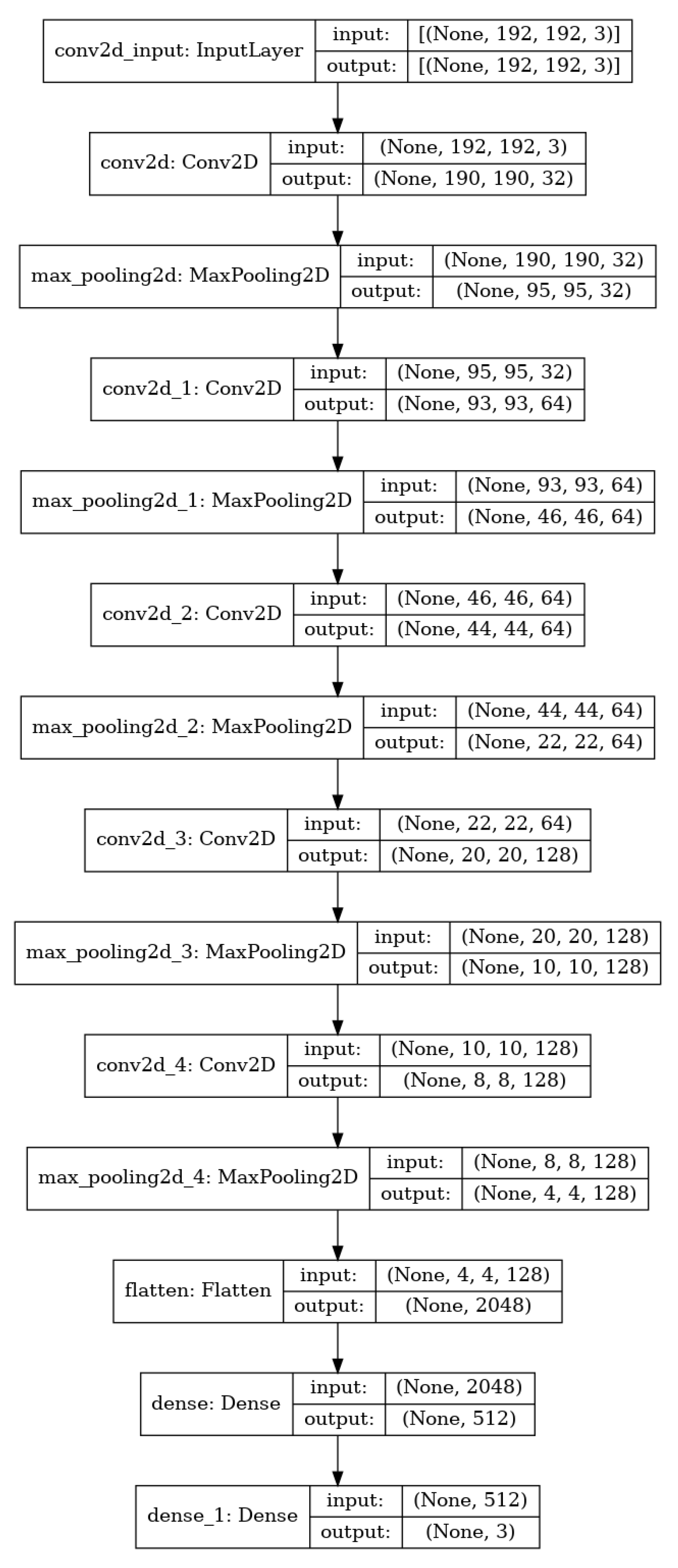
2.3.1. Building a Convolutional Neural Network

Before developing our current process, we built and tested a CNN using Keras, a leading library for neural network design in Python [28]. We also used TensorFlow, a Python library that provides tools for engineers to build machine learning programs for a variety of systems and applications. TensorFlow acts as an interface for Keras to enable smoother development and deployment of machine learning systems [29]. A diagram of our constructed CNN can be found in Figure A1, and a graph of the CNN’s training can be seen in Figure 3. Note that only the best model (smallest validation loss value) is saved during training and that the model would stop training if the validation loss did not improve for five consecutive epochs. As loss decreases, accuracy tends to increase as the model learns. Due to the training settings, the model is only saved when validation loss improves during training.
Our basic CNN also failed to properly identify our gestures under laboratory conditions (using a live webcam feed in our laboratory) because differences of camera angles, backgrounds, lighting, people, and even clothing between pictures can potentially confuse a CNN if it is not trained on an large variety of conditions. To quantify this, we took 420 pictures of 2 of the authors in more diverse environments and ran the CNN on the new set, which can be seen in Figure 4. This returned a test accuracy of 26.84%, which is extremely low, with a test loss of 5.2013, which is very high. Thus, we concluded that the CNN model by itself is insufficient for gesture recognition.
The use of a CNN for classification would have also impeded our system in the long-term: first, we had to determine the position of the gesture in the image, which is possible to add to the program but not feasible in terms of development time. Second, our limited dataset, which consists solely of pictures of one of the authors, introduces the problem of bias. If an engineer is not careful enough and allows their training data to be biased, a machine-learning system—especially a neural network model—might learn to replicate prejudices shown by humans, even if this was not intended by the designer. For example, a facial recognition system that is poorly trained on images of non-Caucasian people might misclassify people with darker skin more often, or an automated hiring software might learn to prefer hiring men over women [30]. Since our dataset consists of a single person, using a CNN for gesture classification introduces an extreme bias in the program’s execution. For these reasons, we chose an alternate method for gesture recognition.

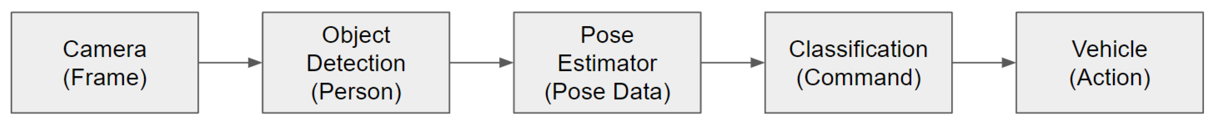
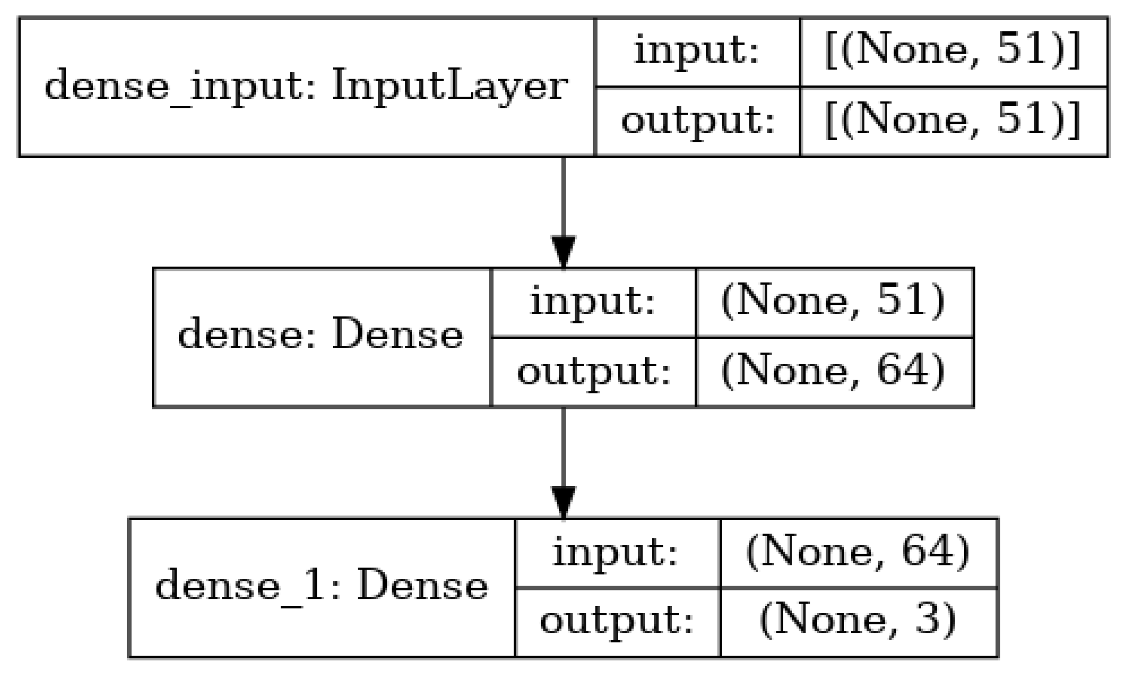
2.3.2. Modular Pipeline Design

To overcome the shortcomings of a pure CNN-based solution, we built a modular pipeline with software reuse and flexibility in mind. We use a combination of complex prebuilt components and comparatively simple custom components to efficiently translate a camera frame into commands for the vehicle. This design paradigm enabled us to develop our system quickly and without major software difficulties, since the most complex parts of the recognition module are prebuilt. A diagram of our pipeline is shown in Figure 5. In practice, our design has elements of older data glove and modern “skeletonization” methods. However, like other models, we use a CNN in combination with additional components [14,15,16,17,18].
We decided to use a TensorFlow pose estimation model (posenet) that is readily available for single-pose (one person) estimation (available here: https://tfhub.dev/google/movenet/singlepose/lightning/4 (accessed on 28 February 2022)). This model takes in an image of size 192 × 192 pixels and returns the estimated positions (x and y values) and confidence scores (how sure the model is that it has marked the point correctly) of 17 points on the body [29,31].
To actually classify the pose, we built a simple DNN. It has as an input layer with 51 neurons (as each pose estimation contains 51 points), one hidden layer with 64 neurons, and an output layer with three neurons (one for each command). A diagram can be seen in Figure 6. To measure the loss of our DNN, we use the categorical crossentropy function.
A diagram of the modular pipeline’s classifier training process can be seen in Figure 7. As in the CNN model, the training process was interrupted after the validation loss did not improve after five consecutive epochs, and only the model with the least validation loss was saved during training.
To generate the input for our gesture recognition model, we start with the object detection results from our pre-existing YOLO-based LFA architecture [24]. YOLO outputs the edges of a bounding box around each person in the image, which we use to crop out a square frame focused on the person for each detection. We then resize this frame to the 192 × 192 target resolution. This is fed into the posenet, which returns the pose estimations. These values are then fed into the classifier, which returns the predicted command. The command is then sent to the vehicle (see Section 3).
Before a target is found, the pipeline searches through all detections in the frame until it finds a start command, at which point it designates that detection as the target and instructs the car to begin following that detection. While following, the object detection only takes the target’s poses into consideration and ignores potential commands from other sources until the target commands the vehicle to stop, at which point the vehicle becomes idle and receptive to commands from any source.
This pipeline is advantageous because it separates the tasks of image recognition and gesture recognition. Image recognition and pose estimation is offloaded to robust pre-trained networks, which means we can use limited gesture datasets without introducing visual bias. Studies of the TensorFlow posenet or YOLOv3’s biases in image recognition are outside the scope of this work.
Our process results in high performance under lab conditions (and as described in Section 4, strong performance in live testing). We also ran it on the same testing dataset that we used to evaluate our CNN, and found that it had a test accuracy of 0.8500 and a test loss of 0.4010. Both results are compiled in Table 2. As the table shows, since the modular design had a far lower test loss and far higher test accuracy than the convolutional design, the modular design is by far better than the CNN by itself. Finally, an image of our pipeline’s operation in experimental conditions are shown in Figure 8. The figure demonstrates that our pipeline is able to correctly classify gestures in a real-world scenario.

3. Vehicle Implementation

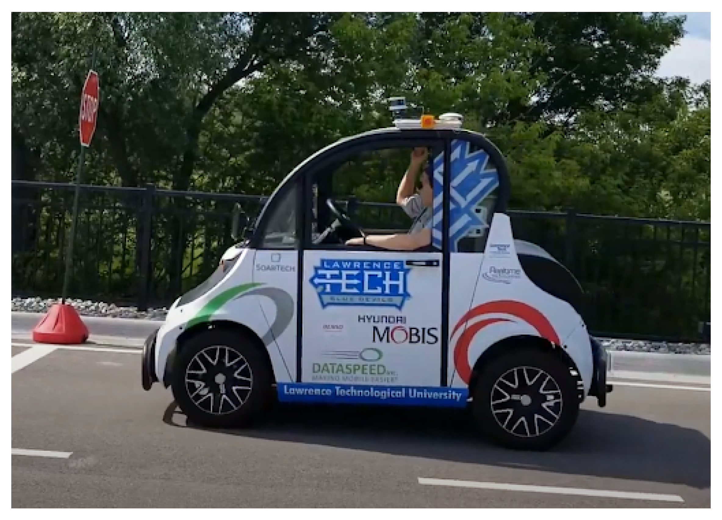
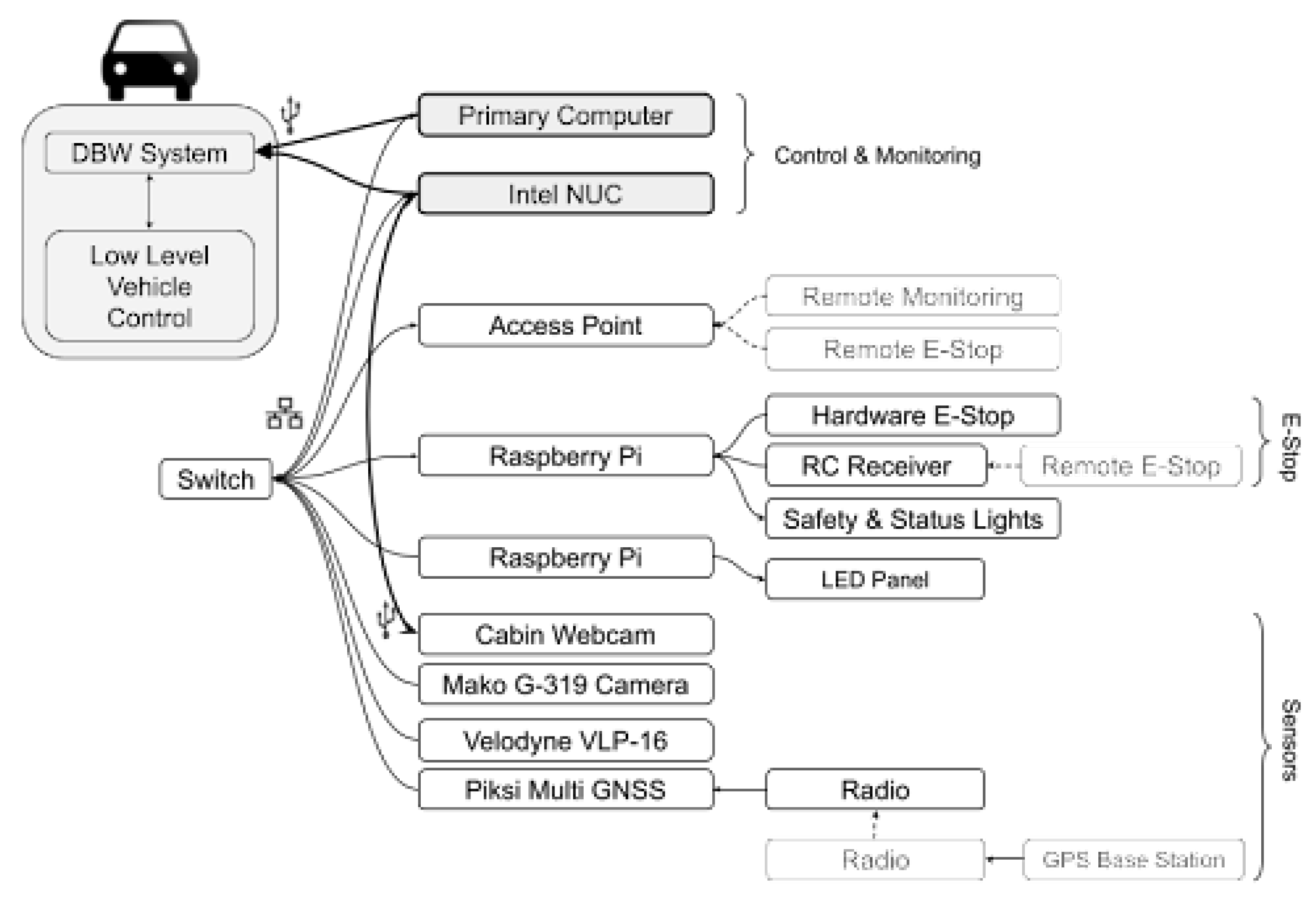
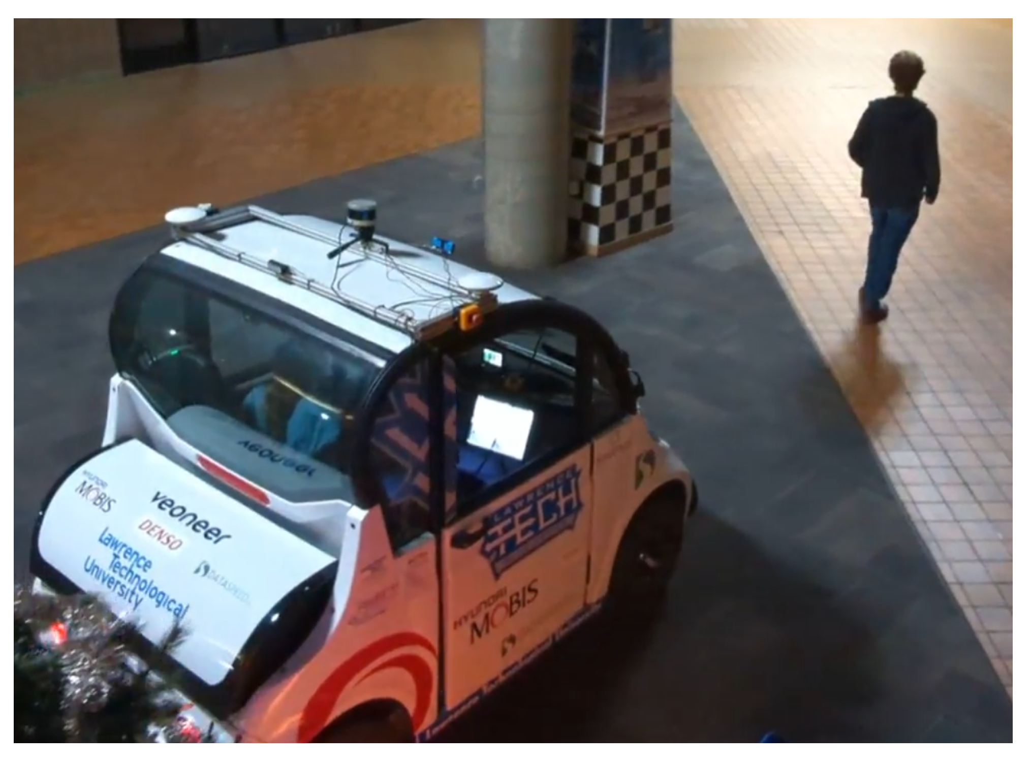
3.1. ACTor 1 Overview

The ACTor 1 (Figure 1) is a Polaris Gem 2 modified with a suite of sensors and computer control. ACTor 1 can be controlled using any one of three computing units: An Intel NUC, a small off-the-shelf desktop computer equipped with an NVIDIA 1070Ti GPU, or a Raspberry PI 3B. These computers can interface with the drive-by-wire system developed by DataSpeed. The vehicle’s sensors include a Velodyne VLP-16 360 degree 16 line 3D LIDAR, Allied Vision Mako G-319C camera with a 6 mm 1stVision LE-MV2-0618-1 lens, and a Piksi Multi GNSS Module. The ACTor’s systems are connected by ethernet and CAN buses. A diagram of our hardware capabilities can be seen in Figure 9 [21].

3.2. ROS Fundamentals

Our research group uses the Robot Operating System (ROS) to interface with the ACTor’s hardware [20]. Despite the name, ROS is not an operating system nor does its use have to be confined to robots. ROS is a platform that provides an abstraction of all hardware with ROS support that allows an engineer to write control programs without needing to know the specifics of each piece of hardware.
ROS systems are structured as a set of implicitly-connected nodes. Each piece of hardware or component program has its own set of nodes through which it can (indirectly) interact with other nodes. Nodes interact using logical channels called topics. The act of broadcasting to the topic is called publishing. Which nodes are receiving the message, if any, are of no concern to the publisher. Nodes listen for messages on topics, which is called subscribing. As with publishers, which nodes are publishing to a topic are of no concern to the subscribers. Nodes can publish or subscribe to as many topics as necessary. Topics have specific message types which generally correspond to established data types, such as integers or timestamps. If the default types are not sufficient, then an engineer may easily create their own message types [22,32].

3.3. ROS Node Design

We have nine nodes running concurrently; a full diagram of our ROS nodes can be seen in Figure 10. Our code is also available here https://github.com/jschulte-ltu/ACTor_Person_Following (accessed on 28 February 2022). We ask that you cite this paper if you intend to use the code for any purpose. Each node is written in ROS for C++, except for Gesture Injection, which is written in ROS for Python.
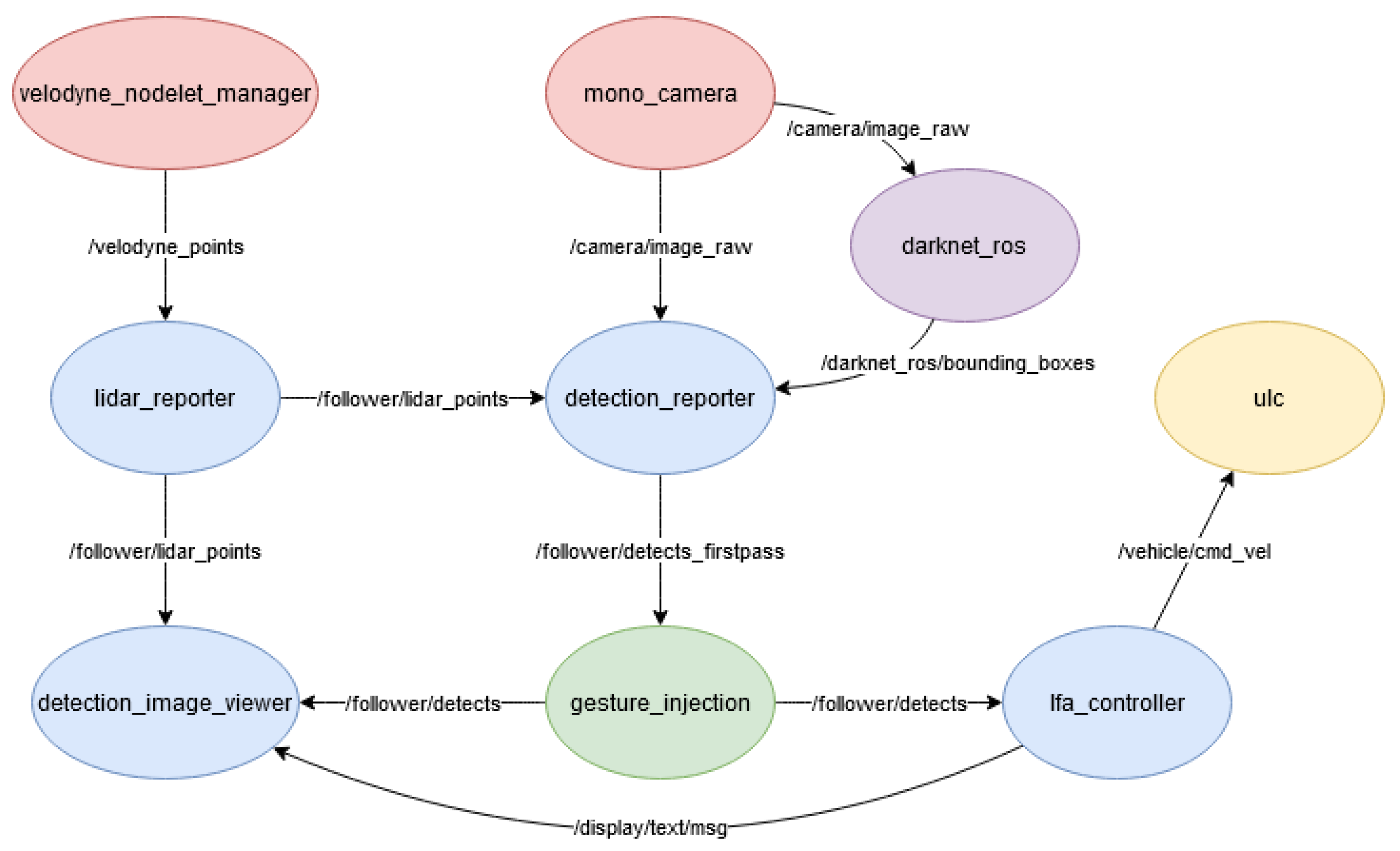
  • Velodyne Nodelet Manager: This node provides an interface from our control unit to the LIDAR. It publishes the LIDAR sensor data for each point on the Velodyne Points topic;
  • Mono Camera: This node provides an interface from our control unit to the camera. It publishes the camera frames on the Image Raw topic;
  • LIDAR Reporter: This node receives raw input from the Velodyne Points topic, packages it into a convenient format, and publishes the reformatted data on the LIDAR Points topic;
  • Darknet ROS: This node subscribes to the Camera topic and runs object detection on camera frames using YOLO. It then publishes the location of each detected object in the image on the Bounding Boxes topic. This node was developed by Joseph Redmon, who also made YOLO [24,33];
  • Detection Reporter: This node subscribes to the Bounding Boxes, LIDAR Points, and Image Raw topics and integrates their data to produce a coherent stream of information. It identifies the human detections reported by YOLO, superimposes their location in the image onto the 3D LIDAR point cloud to find their true location in three dimensions, identifies targets based on the given criteria, and attempts to keep track of the target from frame to frame. It publishes the consolidated information to the Detects Firstpass topic;
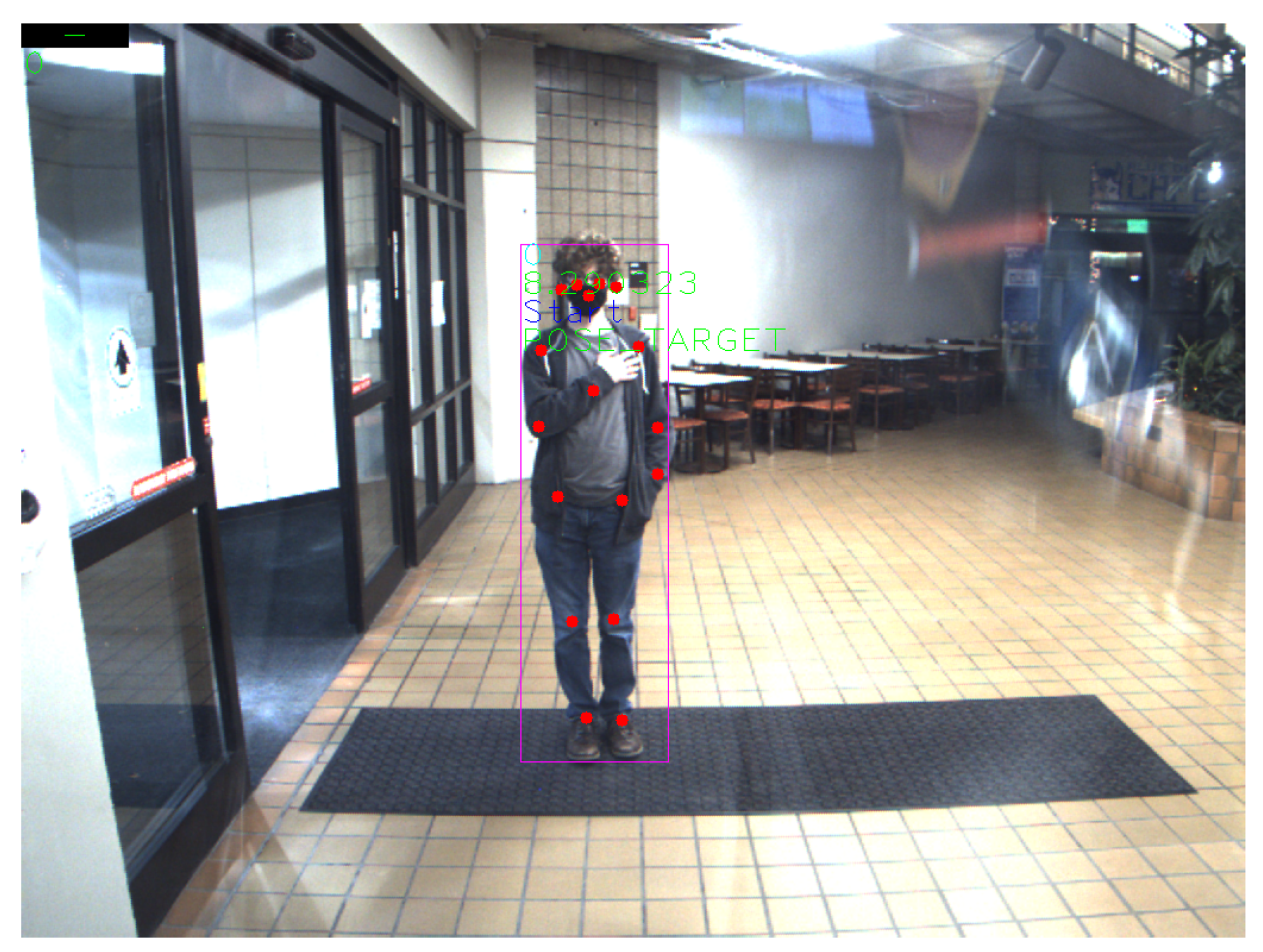
  • Detection Image Viewer: This node subscribes to the LIDAR Points and Detects topics and to produce a visualization of the system’s state. For each detection in the image it draws the bounding box given by YOLO, draws the 17 pose points, and writes their distance from the vehicle’s LIDAR system, the gesture they are performing, and whether or not they are a pose target. It can also superimpose the LIDAR point cloud onto the image and report the current action being performed by the vehicle. This node is purely for monitoring and visualization;
  • Gesture Injection: This node subscribes to the Detects Firstpass topic, implements our gesture recognition pipeline as described in Section 2.3.2 to identify each target’s gesture and the corresponding commands, then republishes the detection information with these new identifications to the Gesture Detects topic. This node serves as a convenient and effective way to splice in the gesture detection pipeline with minimal alterations to our existing code;
  • LFA (Leader Follower Autonomy) Controller: This node subscribes to the Detects, Follower Start and Follower Stop topics and publishes to the Display Message, Display RGB, Enable Vehicle, and ULC command topics. This is the last node in our LFA pipeline, which takes the detection and gesture information generated by the prior nodes and determines the actual commands sent to the vehicle. Those commands are published on the Command Velocity topic;
  • ULC (Universal Lat-Long Controller): This node provides an interface between our control unit and the drive-by-wire system. It takes the command from the Command Velocity topic and translates them into action by the vehicle.

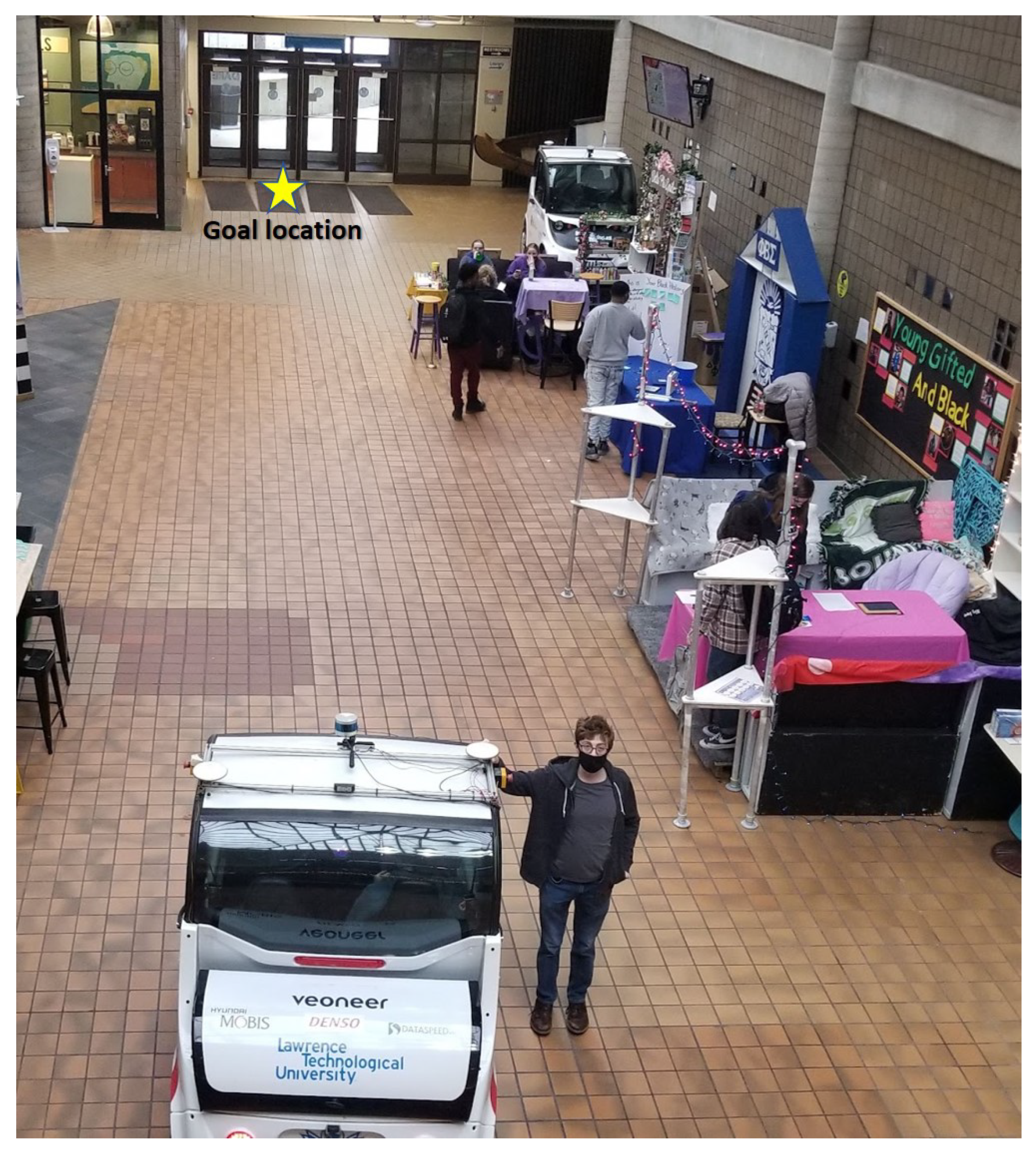
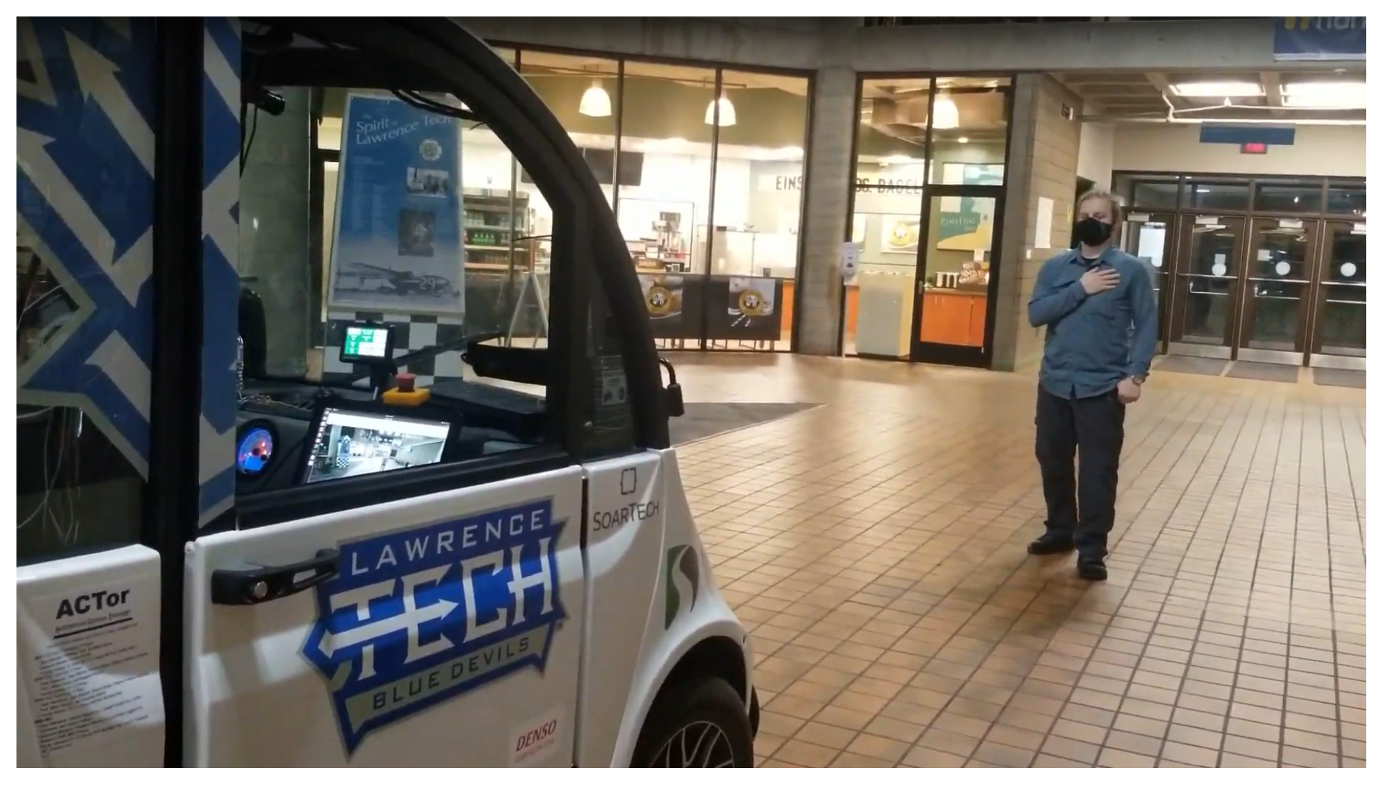
4. Experiment and Results

We ran our experiments on ACTor 1 using its main computing unit, equipped with an AMD Ryzen 7 2700 Processor and a ZOTAC GeForce GTX 1070 Ti GPU [21].
Our testing area was the atrium at Lawrence Technological University. The atrium is a large open indoor area where we store ACTor 1 and ACTor 2. The atrium is the location of the LTU cafeteria, a coffee shop, and a convenience store. It is often the site of university and student-run events. There are numerous seating arrangements, vegetation, noticeboards, and other obstacles. More pertinent to the experiment is that there are usually humans sitting in or walking through the atrium, allowing us to test the system’s robustness to multiple potential sources of input. Another important factor is that due to the large skylight in the building, the atrium is subject to different natural lighting conditions depending on the weather and time of day, which provides us chances to test the robustness of YOLO and our posenet in a variety of lighting conditions.
On the day of the experiment, the atrium had an event, thus providing us with a slightly more complex environment. This can be seen in Figure 11. There were several booths in the atrium and slightly more students than on an average day. Tests were performed between 15:00 and 16:30, during which the outside weather was cloudy. The lighting conditions saw an average luminosity of 402 lx, with a maximum of 625 lx and a minimum of 238 lx.
Our experiments were relatively simple; with the ACTor starting at one end of the atrium, the LFA system would be initialized with a user standing in front of ACTor 1. Once the system is ready, the user would give a stop command to reset any lingering variables, and then give a start command. They would then walk to the other end of the atrium and give a stop command once they have reached the target location, marked with a yellow star in Figure 11. To be a successful trial, the LFA system had to recognize the start gesture, accurately follow the user, and recognize a stop gesture. A video example of our experimental trails is available on YouTube at the following link: https://www.youtube.com/watch?v=6ToP_Kuebj0 (accessed on 28 February 2022). Drive-by-wire system failures were not counted, as the DBW system is outside the scope of this work. There was also a single case where the human operator stopped the vehicle manually as a premature safety decision. This case was also not counted. Figure 12 and Figure 13 demonstrate our system in operation. Another video demonstration of our initial testing is available on YouTube at the following link: https://www.youtube.com/watch?v=A_CExLAEiB0 (accessed on 28 February 2022).
We report 100% success out of 10 trials, not counting the aforementioned cases. Table 3 shows our results. In all trials that were not ended due to unrelated system failures and safety precautions, the gesture-driven LFA system was able to recognize the Start and Stop gestures as well as follow accurately, even when other people were present. However, we have also found two main avenues for future improvement: reducing false-positive gesture detections and improving target persistence.
False-positive gesture detections occur when the gesture recognition classifier predicts that a gesture command is given to it when no actual gesture is being performed. This is caused by information loss from using a two-dimensional pose estimation model. This can make poses difficult to tell apart depending on the user’s orientation, environmental factors, and how the user chooses to enact the pose. We intend to mitigate this issue using a three-dimensional pose estimation model, which we can integrate into the system more easily due to our modular design.
Losses of target persistence occurs when a bystander is close enough to the user so their bounding boxes overlap, such as if the bystander walks in front of the user or if there is a crowd behind the user. Our current architecture uses a simple closest-match algorithm to decide which detection in a new frame corresponds to the target from the previous frame. Thus, if the boxes overlap or the object detection module misses the target for more than one frame, the system can become confused. We intend to overcome this issue using a bipartite mapping algorithm to maintain detection identities between frames. Bipartite mapping is a relationship between two sets in which elements in one set are linked to elements in the other such that no two connections share an element. By finding the best mapping of detections from one frame to the next, taking position, size, and speed into account, it should be able to predictably identify all objects at once rather than only the target.

5. Discussion

5.1. Summary

We have demonstrated that practical and reliable autonomous human-vehicle leader-follower systems are possible and feasible with current technology. We have demonstrated that it is possible to use pre-trained neural network models, namely YOLO, and newly trained DNN classifiers to recognize gesture commands in dynamic environments and translate those commands into actions on an integrated self-driving car computer platform through a pipeline architecture. We use modular software design and software reuse principles to accelerate the development, add new features or functions, improve quality, and limit technical difficulties.

5.2. Future Work

We envision several areas of future development and study. First, we would like to overcome the target persistence and false-positive detection problems discussed in Section 4. Other improvements include further optimizations of our modules to achieve faster processing speeds, thus making the system more responsive. We also recommend adding obstacle detection and path planning modules to make the system safer and more versatile. In addition, we seek to add more gestures to add additional functionality to the system, namely an emergency stop (E-Stop) that can be activated by anyone in the frame. Finally, we believe that tests should be run in more realistic environments and with potential applications in mind.
We mainly envision applications in industrial contexts. The primary use of such a system would be to transport materials, equipment, and parts across factory floors, loading bays, and construction sites with minimal human operation and in some cases far less physical exertion from the human workers. If the proper safety features are present, the use of our system would decrease the chances for human error and improve the health of the workers in these occupations, thus increasing productivity. In non-industrial settings, the human-vehicle leader-follower system could be used in valet parking services. Expanding the gestures to include an automated parking system would allow valet parking—and parking in general—to be more efficient and free from human error.

Author Contributions

Conceptualization, C.-J.C., J.S., M.K., M.P, and N.P.; design methodology, J.S. and M.K.; software implementation, J.S. and M.K.; validation and testing, J.S. and M.K.; data curation, J.S. and M.K.; writing—original draft preparation, M.K.; writing—review and editing, C.-J.C. and J.S.; visualization, M.K. and J.S.; project administration, C.-J.C.; funding and acquisition, C.-J.C.; vehicle setup and maintenance: M.P. and N.P.; vehicle troubleshooting: M.P. and N.P.; All authors have read and agreed to the published version of the manuscript.

Funding

This specific research received no external funding. However the following companies and organizations sponsored the acquisition of ACTor electric vehicles, sensors, on-board computers, by-wire systems, other parts, and vehicle maintenance cost: US Army Ground Vehicle Systems Center, DENSO, SoarTech, Realtime Technologies, GLS&T, Hyundai MOBIS, Dataspeed, NDIA Michigan, Veoneer, and Lawrence Technological University.

Institutional Review Board Statement

Not Applicable.

Informed Consent Statement

Not Applicable.

Data Availability Statement

Not Applicable.

Acknowledgments

The authors thank the Department of Mathematics and Computer Science and the College of Arts and Sciences at Lawrence Technological University for administrative and financial support. The authors also thank ACTor team members Thomas Brefeld, Giuseppe DeRose, Justin Dombecki, and James Golding for their technical support and assistance.

Conflicts of Interest

The authors declare no conflict of interest.

Appendix A

Figure A1. Diagram of a basic Convolutional Neural Network.
Vehicles 04 00016 g0a1

References

  1. Consolini, L.; Morbidi, F.; Prattichizzo, D.; Tosques, M. Leader-follower formation control of nonholonomic mobile robots with input constraints. Automatica 2008, 44, 1343–1349. [Google Scholar] [CrossRef]
  2. Cheok, K.; Iyengar, K.; Oweis, S. Smooth Trajectory Planning for Autonomous Leader-Follower Robots. In Proceedings of the 34th International Conference on Computers and Their Applications, Honolulu, HA, USA, 18–20 March 2019; EPiC Series in, Computing. Lee, G., Jin, Y., Eds.; EasyChair: Manchester, UK, 2019; Volume 58, pp. 301–309. [Google Scholar] [CrossRef] [Green Version]
  3. Ramadan, A.; Hussein, A.; Shehata, O.; Garcia, F.; Tadjine, H.; Matthes, E. Dynamics Platooning Model and Protocols for Self-Driving Vehicles. In Proceedings of the 2019 IEEE Intelligent Vehicles Symposium, Paris, France, 9–12 June 2019; pp. 1974–1980. [Google Scholar] [CrossRef]
  4. Ng, T.C.; Guzman, J.; Adams, M. Autonomous vehicle-following systems: A virtual trailer link model. In Proceedings of the 2005 IEEE/RSJ International Conference on Intelligent Robots and Systems, Edmonton, AB, Canada, 2–6 August 2005; pp. 3057–3062. [Google Scholar] [CrossRef]
  5. Kehtarnavaz, N.; Griswold, N.; Lee, J. Visual control of an autonomous vehicle (BART)-the vehicle-following problem. IEEE Trans. Veh. Technol. 1991, 40, 654–662. [Google Scholar] [CrossRef]
  6. Simonsen, A.S.; Ruud, E.L.M. The Application of a Flexible Leader-Follower Control Algorithm to Different Mobile Autonomous Robots. In Proceedings of the 2020 IEEE/RSJ International Conference on Intelligent Robots and Systems (IROS), Las Vegas, NV, USA, 24 October–24 January 2021; pp. 11561–11566. [Google Scholar] [CrossRef]
  7. Lakshmanan, S.; Yan, Y.; Baek, S.; Alghodhaifi, H. Modeling and simulation of leader-follower autonomous vehicles: Environment effects. In Unmanned Systems Technology XXI; Shoemaker, C.M., Nguyen, H.G., Muench, P.L., Eds.; International Society for Optics and Photonics, SPIE: Bellingham, WA, USA, 2019; Volume 11021, pp. 116–123. [Google Scholar]
  8. Solot, A.; Ferlini, A. Leader-Follower Formations on Real Terrestrial Robots. In Proceedings of the ACM SIGCOMM 2019 Workshop on Mobile AirGround Edge Computing, Systems, Networks, and Applications, Beijing, China, 19 August 2019; Association for Computing Machinery: New York, NY, USA, 2019. MAGESys’19. pp. 15–21. [Google Scholar] [CrossRef]
  9. Kehtarnavaz, N.; Groswold, N.; Miller, K.; Lascoe, P. A transportable neural-network approach to autonomous vehicle following. IEEE Trans. Veh. Technol. 1998, 47, 694–702. [Google Scholar] [CrossRef]
  10. Tang, Q.; Cheng, Y.; Hu, X.; Chen, C.; Song, Y.; Qin, R. Evaluation Methodology of Leader-Follower Autonomous Vehicle System for Work Zone Maintenance. Transp. Res. Rec. 2021, 2675, 107–119. [Google Scholar] [CrossRef]
  11. Setiawan, S.; Yamaguchi, J.; Hyon, S.H.; Takanishi, A. Physical interaction between human and a bipedal humanoid robot-realization of human-follow walking. In Proceedings of the 1999 IEEE International Conference on Robotics and Automation (Cat. No.99CH36288C), Detroit, MI, USA, 10–15 May 1999; Volume 1, pp. 361–367. [Google Scholar] [CrossRef] [Green Version]
  12. Morioka, K.; Lee, J.H.; Hashimoto, H. Human-following mobile robot in a distributed intelligent sensor network. IEEE Trans. Ind. Electron. 2004, 51, 229–237. [Google Scholar] [CrossRef]
  13. More Info about Travelmate. 2021. Available online: https://travelmaterobotics.com/more-info-about-travelmate/ (accessed on 26 September 2021).
  14. Murakami, K.; Taguchi, H. Gesture recognition using recurrent neural networks. In Proceedings of the SIGCHI Conference on Human Factors in Computing Systems, New Orleans, LA, USA, 27 April–2 May 1991; pp. 237–242. [Google Scholar]
  15. Fang, W.; Ding, Y.; Zhang, F.; Sheng, J. Gesture recognition based on CNN and DCGAN for calculation and text output. IEEE Access 2019, 7, 28230–28237. [Google Scholar] [CrossRef]
  16. Hu, Y.; Wong, Y.; Wei, W.; Du, Y.; Kankanhalli, M.; Geng, W. A novel attention-based hybrid CNN-RNN architecture for sEMG-based gesture recognition. PLoS ONE 2018, 13, e0206049. [Google Scholar] [CrossRef] [PubMed] [Green Version]
  17. Jiang, D.; Li, G.; Sun, Y.; Kong, J.; Tao, B. Gesture recognition based on skeletonization algorithm and CNN with ASL database. Multimed. Tools Appl. 2019, 78, 29953–29970. [Google Scholar] [CrossRef]
  18. Wu, X.Y. A hand gesture recognition algorithm based on DC-CNN. Multimed. Tools Appl. 2020, 79, 9193–9205. [Google Scholar] [CrossRef]
  19. Schulte, J.; Dombecki, J.; Pleune, M.; DeRose, G.; Paul, N.; Chung, C. Developing Leader Follower Autonomy for Self-driving Vehicles Using Computer Vision and Deep Learning. Lawrence Technological University Eighth Annual Research Day, Poster Presentation 2021. Available online: http://qbx6.ltu.edu/chung/papers/LeaderFollower.pdf (accessed on 28 February 2022).
  20. Paul, N.; Pleune, M.; Chung, C.; Warrick, B.; Bleicher, S.; Faulkner, C. ACTor: A Practical, Modular, and Adaptable Autonomous Vehicle Research Platform. In Proceedings of the 2018 IEEE International Conference on Electro/Information Technology (EIT), Rochester, MI, USA, 3–5 May 2018; pp. 0411–0414. [Google Scholar] [CrossRef]
  21. DeRose, G.; Brefeld, T.; Dombecki, J.; Pleune, M.; Schulte, J.; Paul, N.; Chung, C. ACTor: IGVC Self-Drive Design Report. 2021. Available online: https://robofest.net/igvc/IGVC2021DesignReport_LTU.pdf (accessed on 28 February 2022).
  22. Stanford Artificial Intelligence Laboratory. Robotic Operating System. 2018. Available online: https://www.ros.org (accessed on 28 February 2022).
  23. OpenCV: Detection of ArUco Markers. 2021. Available online: https://docs.opencv.org/master/d5/dae/tutorial_aruco_detection.html (accessed on 28 February 2022).
  24. Redmon, J.; Farhadi, A. YOLOv3: An Incremental Improvement. arXiv 2018, arXiv:1804.02767. [Google Scholar]
  25. Peltarion. Categorical Crossentropy. Available online: https://peltarion.com/knowledge-center/documentation/modeling-view/build-an-ai-model/loss-functions/categorical-crossentropy (accessed on 21 December 2021).
  26. Chollet, F. Deep Learning with Python, 1st ed.; Apress: Berkeley, CA, USA, 2017; Manning. [Google Scholar]
  27. Dongare, A.; Kharde, R.; Kachare, A.D. Introduction to artificial neural network. Int. J. Eng. Innov. Technol. (IJEIT) 2012, 2, 189–194. [Google Scholar]
  28. Keras. 2015. Available online: https://keras.io (accessed on 28 February 2022).
  29. Abadi, M.; Agarwal, A.; Barham, P.; Brevdo, E.; Chen, Z.; Citro, C.; Corrado, G.S.; Davis, A.; Dean, J.; Devin, M.; et al. TensorFlow: Large-Scale Machine Learning on Heterogeneous Systems. 2015. Software. Available online: tensorflow.org (accessed on 28 February 2022).
  30. Caliskan, A.; Bryson, J.; Narayanan, A. Semantics derived automatically from language corpora contain human-like biases. Science 2017, 356, 183–186. [Google Scholar] [CrossRef] [PubMed] [Green Version]
  31. Alphabet Inc. movenet/singlepose/lightning. 2021. Available online: https://tfhub.dev/google/movenet/singlepose/lightning/4 (accessed on 28 February 2022).
  32. O’Kane, J.M. A Gentle Introduction to ROS; CreateSpace Independent Publishing Platform: Scotts Valley, CA, USA, 2014; Available online: http://www.cse.sc.edu/~jokane/agitr/ (accessed on 28 February 2022).
  33. Redmon, J. Darknet: Open Source Neural Networks in C. 2013–2016. Available online: http://pjreddie.com/darknet/ (accessed on 28 February 2022).
Figure 1. An image of ACTor 1 [21].
Vehicles 04 00016 g001
Figure 2. Each of the three poses depicted by author J. Schulte. (a) Command to follow the user and label them as the target. (b) Command to stop following the user. (c) No Command: follow previous command.
Vehicles 04 00016 g002
Figure 3. Graphs of the the CNN model’s training process. On the left, the categorical crossentropy values for the training and validation sets are plotted by epoch. On the right, training and validation accuracy (proportion of correctly predicted labels) are plotted by epoch.
Vehicles 04 00016 g003
Figure 4. Examples of the testing dataset. When compared to the pictures in Figure 2, it is easy to see that the backgrounds are very different and author J. Schulte is wearing different clothes. This easily confuses basic CNN models but does not confuse our modular design. (a) Command to follow the user and label them as the target. (b) Command to stop following the user. (c) No Command: follow previous command.
Vehicles 04 00016 g004
Figure 5. Our pipeline for gesture recognition and the resultant actions by the vehicle. This diagram is formatted as Component (Returns). The camera returns a frame, and the object detection takes the frame and returns a cropped photo of the person it is currently targeting. The pose estimation then uses this to return the estimated pose data. This is then given to the classifier, which predicts a command that is then sent to the vehicle, which finally performs an action.
Vehicles 04 00016 g005
Figure 6. Automatically generated diagram of our classification NN. The first column is formatted as layer_name: LayerType and describes what kind of layer it is. The second and third columns describe the input and output of each layer. None indicates that the amount of inputs or outputs might be variable, but the number associated indicates how many values each input or output should/will have.
Vehicles 04 00016 g006
Figure 7. Graphs of the the modular classifier’s training process. On the left, the categorical crossentropy values for the training and validation sets are plotted by epoch. On the right, training and validation accuracy are plotted by epoch. This classifier is the component in the fourth box (“classification”) in Figure 5.
Vehicles 04 00016 g007
Figure 8. Our modular system performing gesture recognition on author M. Kocherovsky. YOLO determines the location of the author in the frame, which generates the pink bounding box surrounding him. The posenet component determines the location of the main joints and other key features on the author’s body, which are displayed as red squares. Finally, the gesture recognition module has correctly identified the author’s gesture as follow, and has marked him as the Pose Target, meaning that the vehicle will follow his movements.
Vehicles 04 00016 g008
Figure 9. An image of the ACTor 1 hardware setup [21].
Vehicles 04 00016 g009
Figure 10. A diagram of the main ROS Nodes (ellipses) and topics (arrows) specific to our leader follower system. Nodes marked in red indicate hardware nodes which publish sensor data. Blue nodes represent helper nodes. The Darknet ROS node manages object detection, Gesture Injection runs the pose estimation and classification, and ULC manages interactions with the vehicle’s drive-by-wire system.
Vehicles 04 00016 g010
Figure 11. Author M. Kocherovsky poses with ACTor 1 before an experimental trial. The yellow star denotes the approximate target location. Picture taken by author CJ Chung.
Vehicles 04 00016 g011
Figure 12. Author J. Schulte gives ACTor 1 the follow command. Author M. Kocherovsky sits in the driver’s seat as a safety precaution. Picture taken by author CJ Chung.
Vehicles 04 00016 g012
Figure 13. ACTor 1 autonomously follows author M. Kocherovsky in the atrium of Lawrence Technological University. Author J. Schulte sits in the driver’s seat as a safety precaution. Picture taken by author M. Pleune.
Vehicles 04 00016 g013
Table 1. List of visual gestures and their corresponding functions.
GestureCommand
Hand on HeartBegin Following
Palm out to the SideStop Following
NeitherNo Change
Table 2. Comparison of CNN and modular designs when evaluated on the same testing dataset. Higher accuracy values and lower loss values indicate better models.
ModelTest LossTest Accuracy
CNN5.20130.2684
Modular0.40100.8500
Table 3. Summary of experimental trials. We report 100% success of the gesture-driven LFA system. Unrelated ACTor 1 system failures and trials ended due to safety precautions were not counted.
TrialStartFollowed UserStopOthers AroundSuccess
1YYYNY
2YYYNY
3YYYNY
4YYY1 Person Behind UserY
5YYY1 Person Behind UserY
6YYYNY
7YYYOthers in vicinityY
8YYY1 Person Behind UserY
9YYY1 Person Behind UserY
10YYYNY
Publisher’s Note: MDPI stays neutral with regard to jurisdictional claims in published maps and institutional affiliations.

