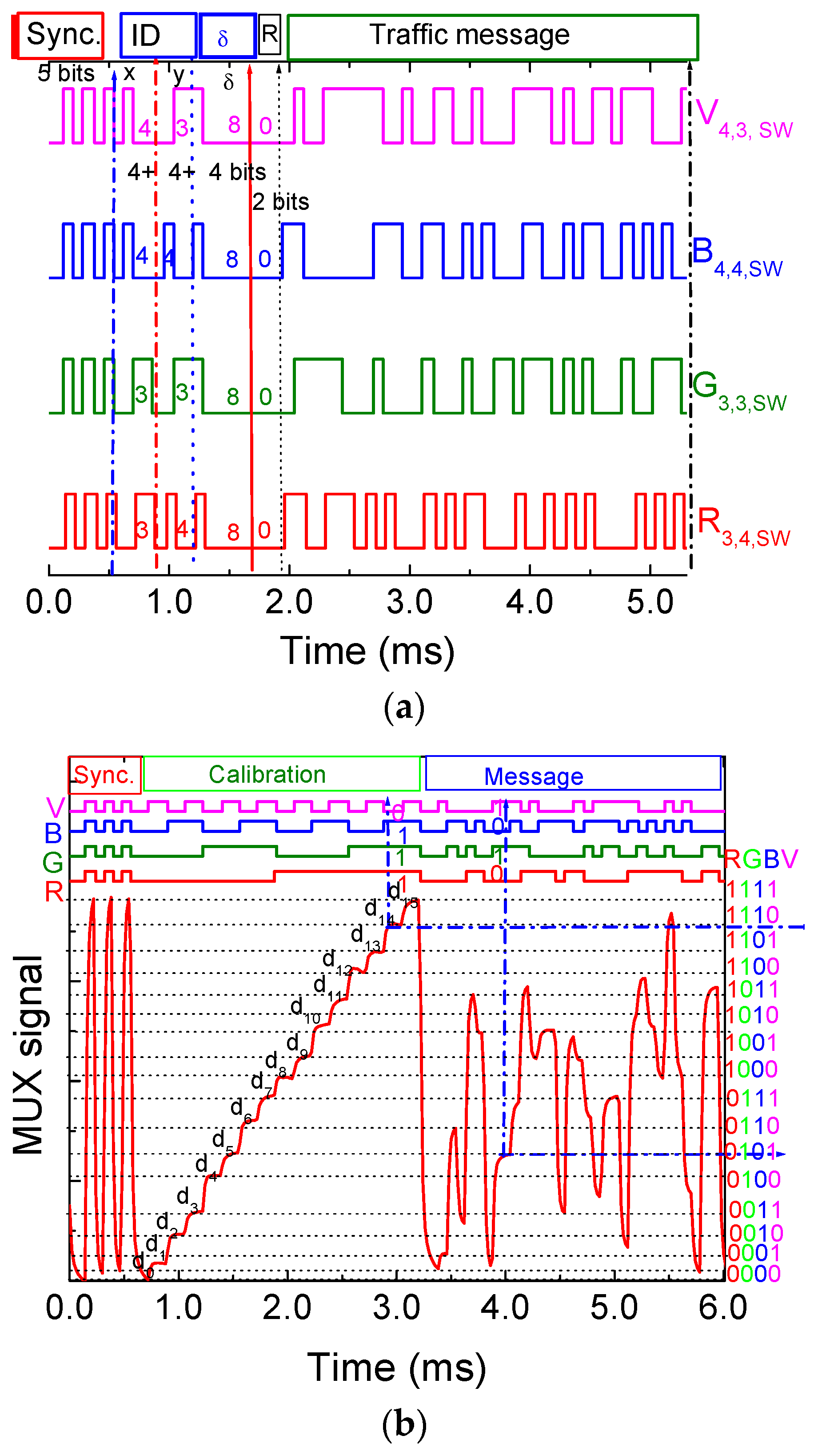
4.1. Communication Protocol and Coding/Decoding Techniques
To code the information, an On–Off keying (OOK) modulation scheme was used and it was considered a synchronous transmission based on data frame of 64 bits. A data frame is exemplified in
Figure 6.
If the transmitter is a streetlamp or headlamp, the frame is divided into four blocks; if the transmitter is the traffic light, five blocks are considered. The first block is the synchronization block [10101], the last is the payload data (traffic message) and a strop bit ends the frame. The ID block gives the location (
x,
y coordinates) of the emitters inside the array (X
i,j). Cell’s IDs are encoded using a 4 bit binary representation for the decimal number. The δ block (steering angle (
δ)) completes the pose in a frame time
q(
x,
y,
δ,
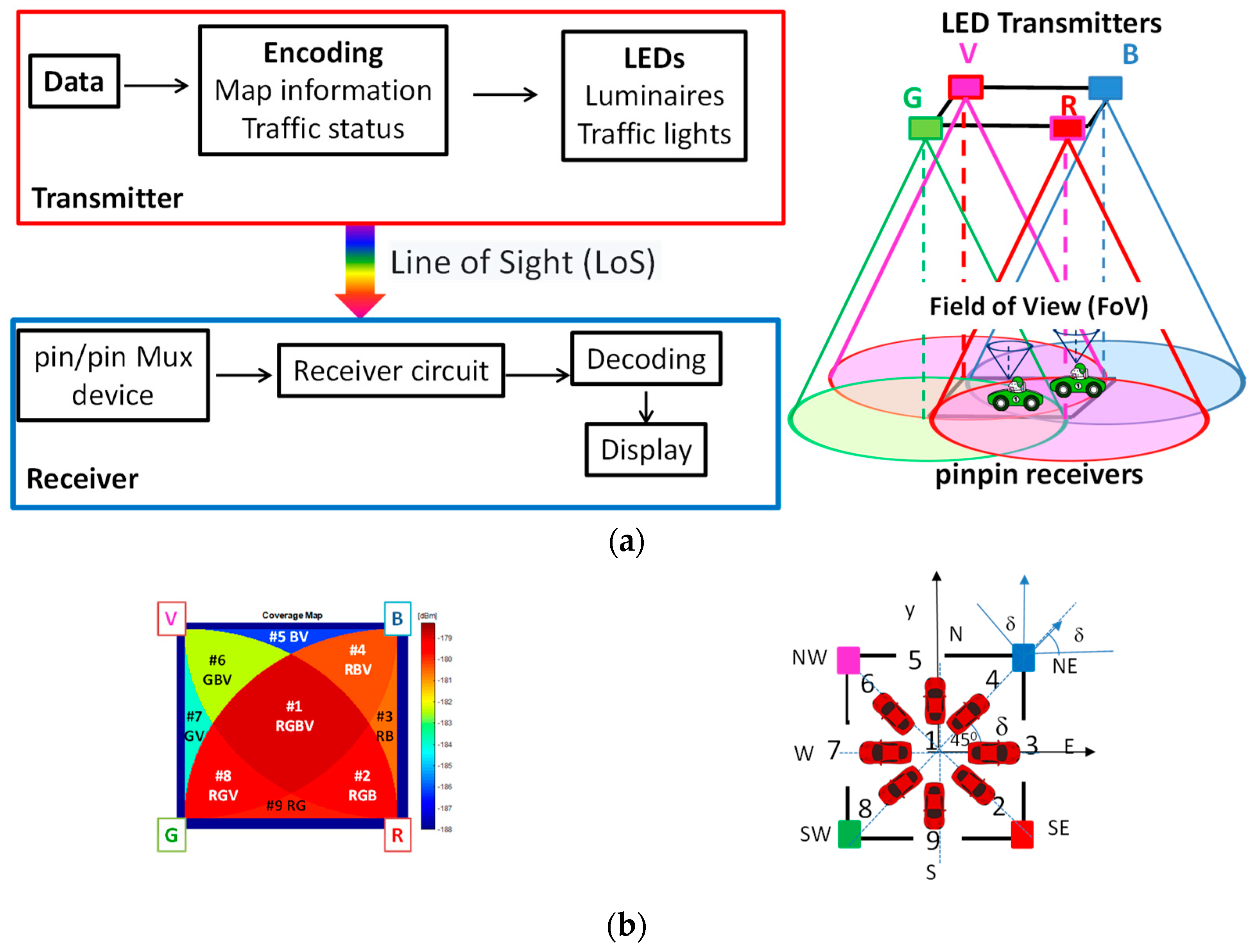
t). Eight steering angles along the cardinal points and coded with the same number of the footprints in the unit cell (
Figure 1b) are possible from a start point to the next goal. If the message is diffused by the IM transmitter, a pattern [0000] follows this identification, if it is a request (R) a pattern [00] is used. The decimal numbers assigned to each ID block are pointed out in
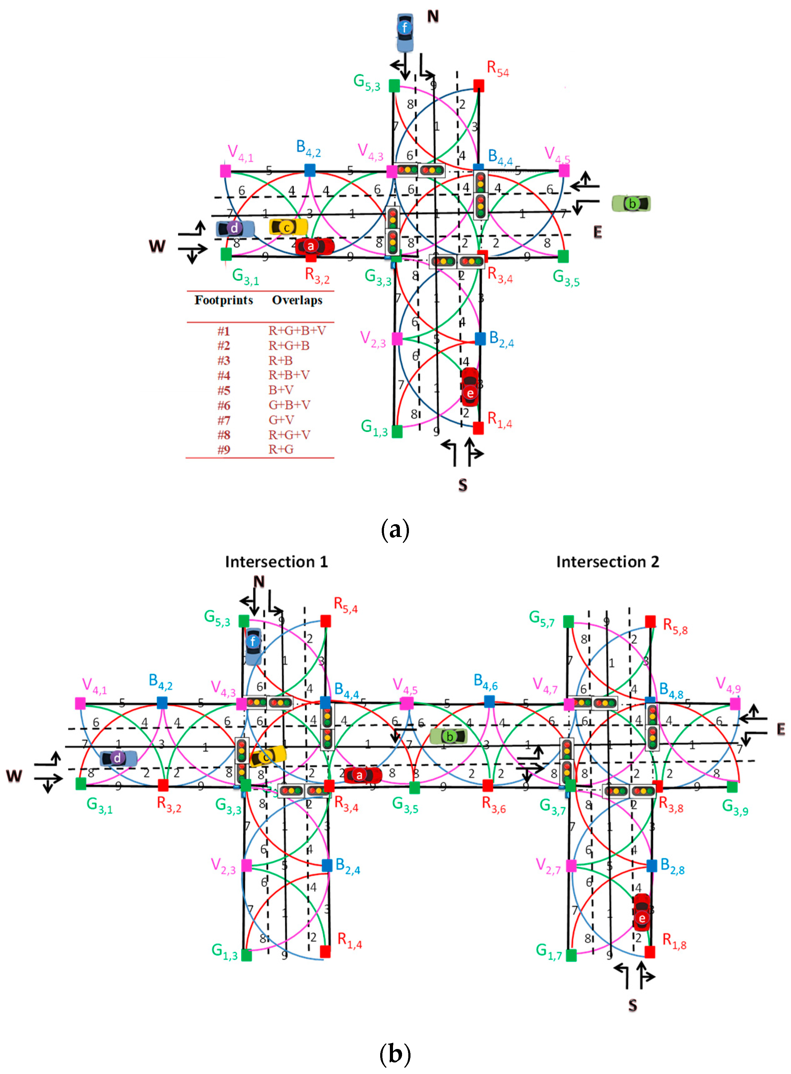
Figure 6a. So, in this time slot, R
3,4,Sw; G
3,3,Sw; B
4,4,Sw and V
4,3,Sw are the transmitted node packets, from the crossroad 1. Here, the driver receives his request message [pose, and traffic needs] from the infrastructure. This allows it movement across the crossroad to southwest (code 8), directly from the current point (#1) to the goal point (#8).
Based on the measured photocurrent signal by the photodetector, it is necessary to decode the information received. For this purpose, a calibration curve is previously defined to establish this assignment. In
Figure 6b, calibration curve that uses 16 distinct photocurrent thresholds resultant from the combination of the RGBV-modulated signals from the VLC emitter is plotted [
29]. The correspondence between each footprint and the photocurrent level is highlighted on the right side of
Figure 6b. Here, the MUX signal obtained at the receiver as well as the coded transmitted optical signals is displayed. The message, in the frame, start with the header labelled as Sync, a block of 5 bits [10101] imposed simultaneously to all the emitters. In the calibration block (second block), four calibrated R, G, B, and V optical signals are transmitted at the same time. Here, the bit sequence was chosen to allow all the
on/off sixteen possible combinations of the four RGBV input channels (2
4). In the last block, a random message is transmitted. A periodic retransmission of the calibration curve is needed to ensure the correspondence to the output signal and an precise decoding of the transmitted information. Comparing the calibrated levels (d
0–d
15) with the assigned 4-digit binary [RGBV] codes, ascribed to each level (pointed out at the right side of
Figure 6b), the decoding is straightforward, and the message decoded. Taking into account the frame structure (
Figure 6a), after decoding the MUX signals, the pose (position and direction), the kind of transmitter (IM or Vehicle) and traffic message are revealed [
30].
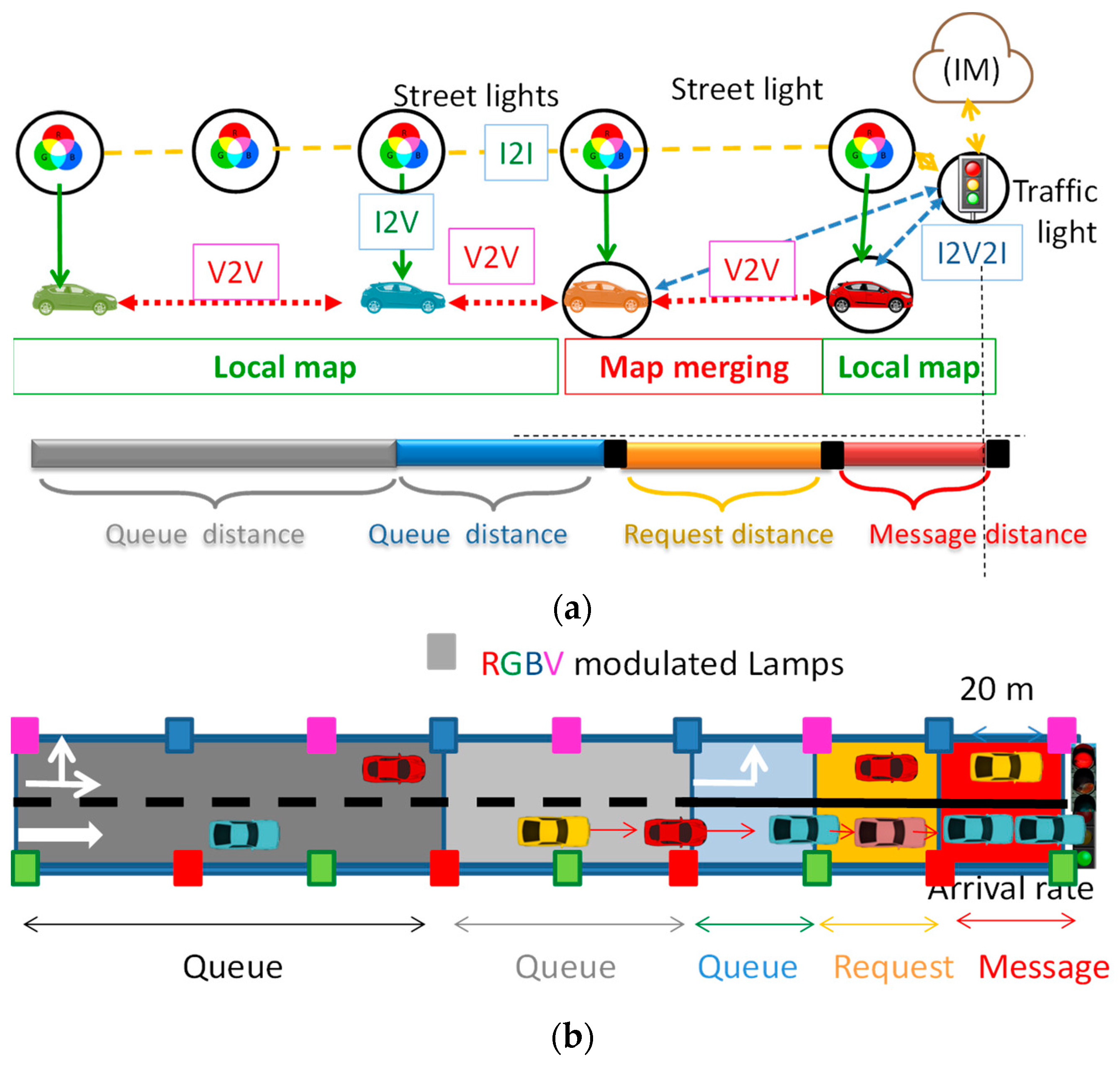
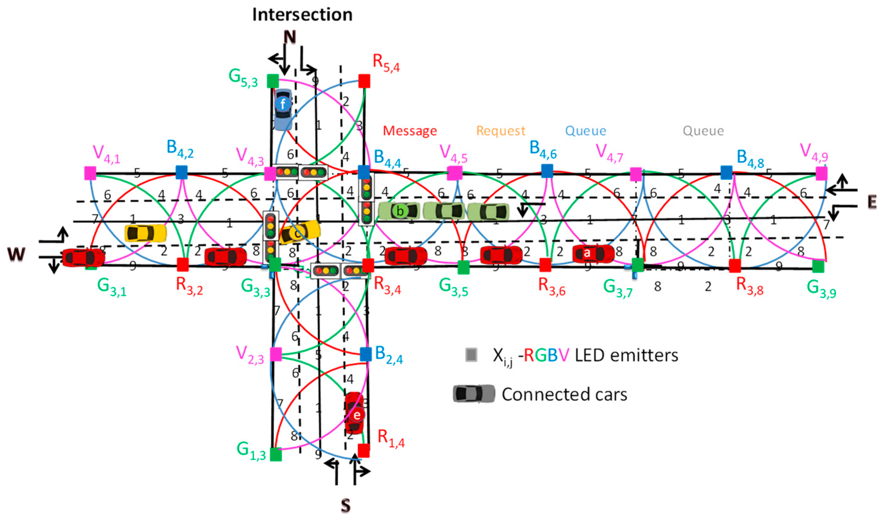
4.2. The Cooperative VLC System
In
Figure 2, a traffic scenario was simulated using VLC cooperative communication. In the lab, as PoC, it was tested by moving the receiver along known paths. The worst-case scenario was modeled. Here, vehicles
a,
b,
c and
d, oncoming both intersections have a conflicting trajectory. When they reach the request distance (see
Figure 4), they send a request to the traffic light controller (V2I) that faces the lane, asking permission to cross the intersection. If they receive permission (I2V), they go forward or turn left depending on the occupied lane, otherwise stop at the respective stop lines within the message distance. Four crossing different instants are considered: the request (
t) and the response (
t′) times, and also the crossroad enter (
t″) and the exit (
t‴) times. All the requests comprise vehicle positions and approach speeds. If a follower exists (vehicle
d), the request message from its leader,
c, includes the position and speed previously received by V2V. This information alerts the controller to a later request message (V2I), confirmed by the follow vehicle. We have assumed that, in the four-legged intersection
ta <
tb <
tc <
te <
td <
tf. In the split, for Intersection 1:
ta <
tc <
td = tb <
tf; and for Intersection 2:
ta = tb <
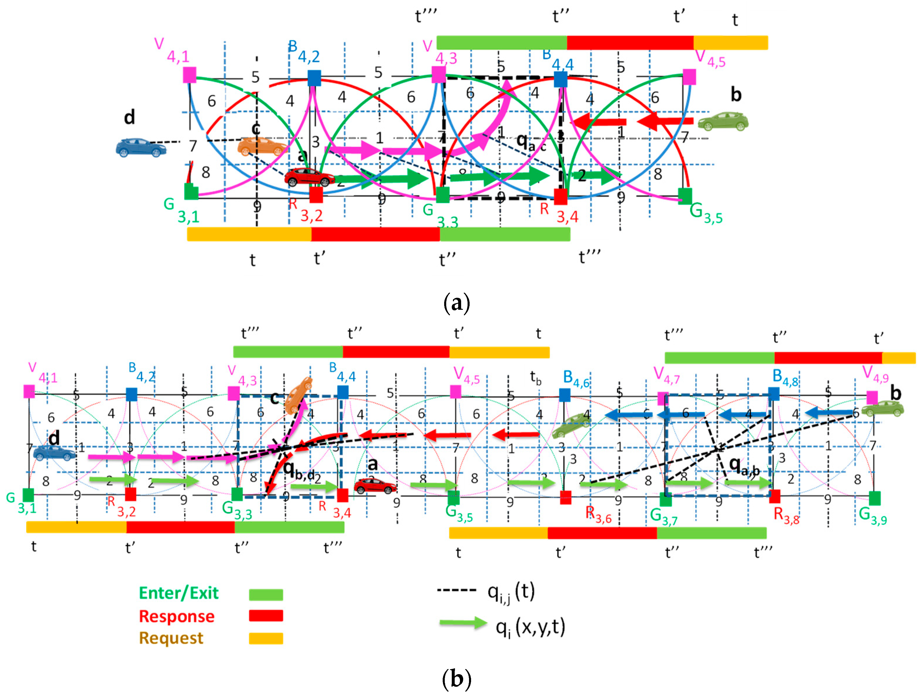
te. In
Figure 7, the movement of the cars, in the successive moments, with their colorful poses (color arrows) and
qi,j spatial relative poses (dot lines), is displayed for a four-legged intersection (a) and for a split one (b).
In coordinating traffic signals (
Figure 7b), we assume that a vehicle’s movement along a main street (W > E) can be predictable, and the two intersections referred to as one entity, the interchange. Thus, any reference to signal timing includes not only the joint set of phasing patterns at the two intersections, but also the cycle length and the offset relationship between the two intersections. The option of using two linked controllers provides the maximum flexibility because it allows the use of all phasing patterns for the pair of intersections.
We denote
q,
q′,
q″,
q‴ as the vehicle pose estimation at the time
t,
t′,
t″,
t‴ (request, response, enter and exit times), respectively. To estimate these variables, it is possible to take advantage of what is defined as control inputs, and which represent an estimation of the motion along the time. The vehicle speed can be calculated by measuring the actual travelled distance overtime, using the ID’s transmitter tracking. Two measurements are required: distance and elapsed time. The distance is fixed while the lapsed time is obtained using the times where the footprint region changes. There is a fixed spacing between reference points (
Figure 2), but the correspondent time integrated by the receiver varies depending on how fast the vehicle is going. The receivers compute the geographical position in the successive instants (path) and infer the vehicle’s speed. When there are two neighboring vehicles in different lanes, the geometric relationship between them (
qi,j; dotted lines in
Figure 7) can be inferred through local SLAM fusing their self-localizations via a chain of geometric relationships among the vehicles poses and the local maps.
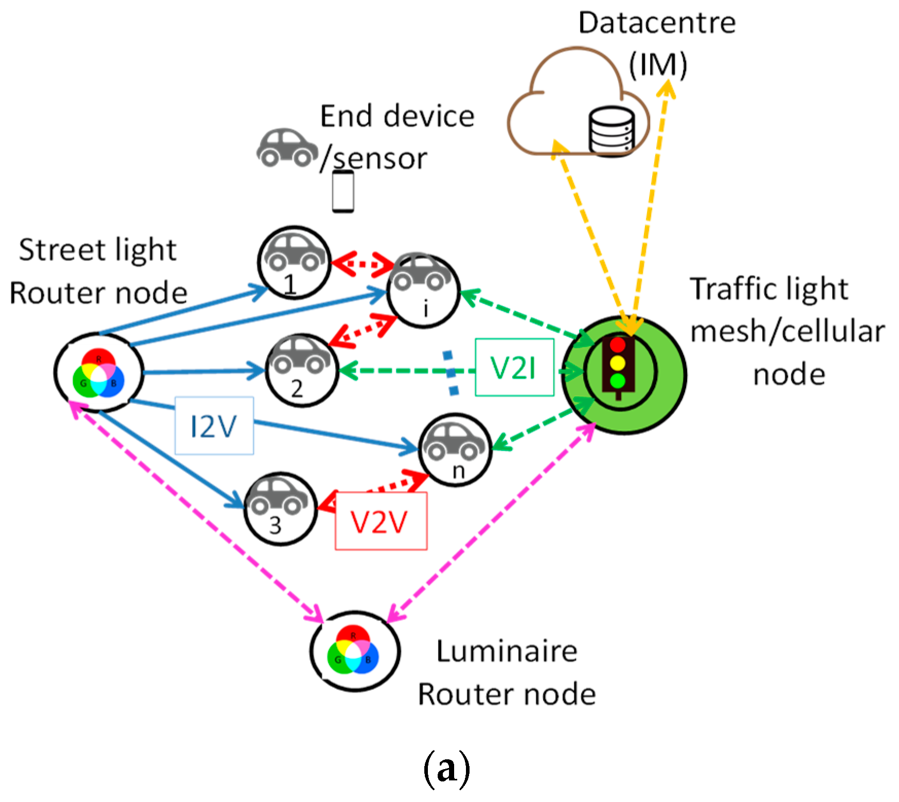
For a vehicle with several neighboring vehicles, the mesh node (
Figure 4) uses the indirect V2V relative pose estimations method taking advantage of the data of each neighboring vehicle. As an example, for vehicle
d, two instants can be considered,
t and
t′. To help control the flow of vehicle
b, the request the vehicle
c leader, has to include its position and speed, earlier received by the V2V. This alerts the controller to a later request (V2I), set by the follow vehicle
d, at
t′
d.
Comparing the two types of intersections, in
Figure 7a, vehicle
b with a request at
tb only pass Phase 3 (see
Figure 5) after waiting, at the stop line, for vehicle
a to exit the intersection (
t‴
a) and vehicle
d to approach it. At the split intersection (
Figure 7b), it will approach Intersection 1 simultaneously with vehicle
d. For this to happen, the IM foresees the entry of vehicle
b (
t″
b) at Intersection 2, as well as the entry of vehicle
a (
t′
a) at Phase 1, using an appropriate
offset between both intersections.
4.3. V-VLC Experimental Evaluation
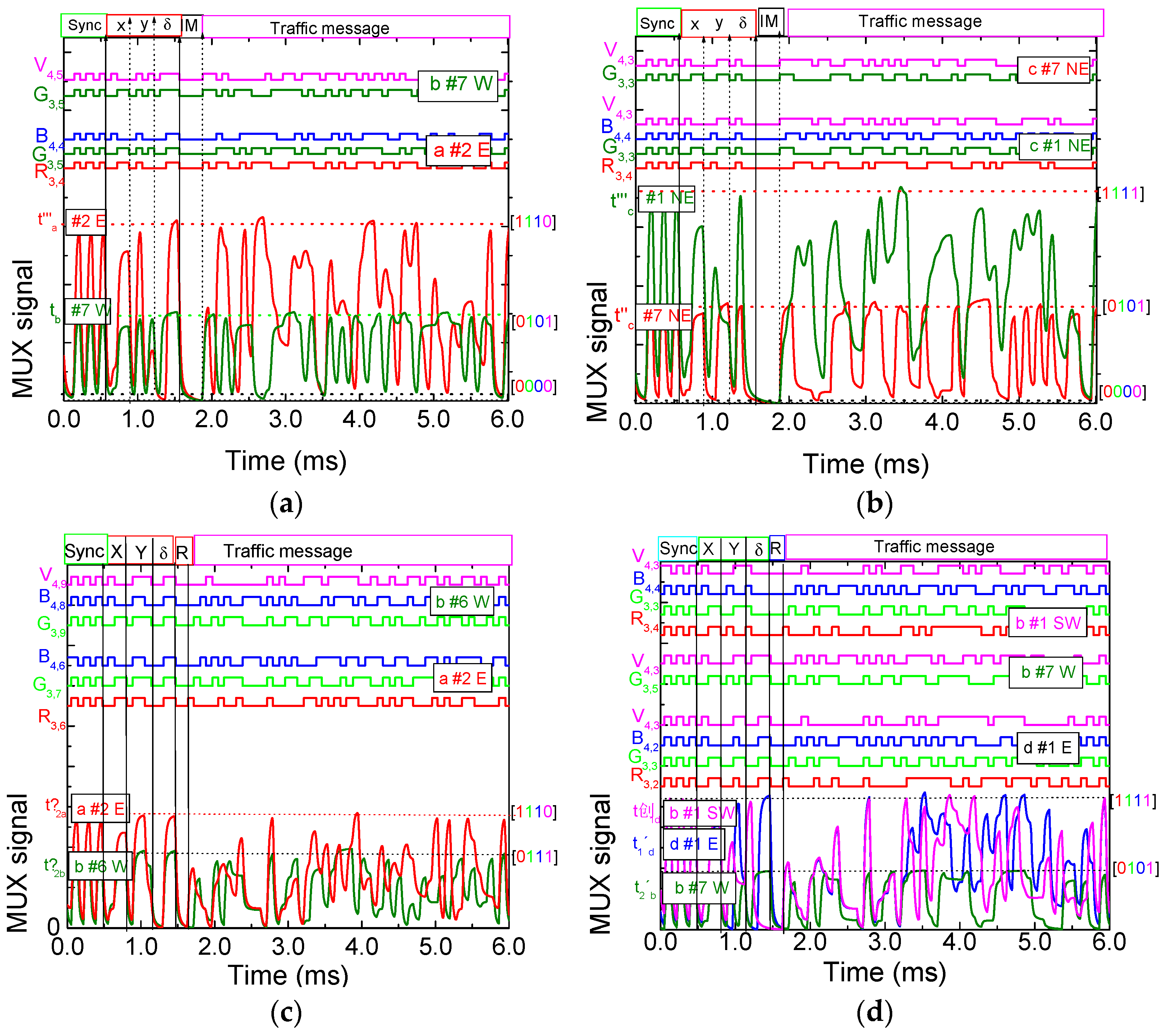
As an example, the I2V MUX signals received and decoded (on top of the figures) by the receiver of each vehicle
a,
b,
c, and d are shown in the figures, for the four-legged (
Figure 8a,b) and for the split (
Figure 8c,d) intersections, at different frame times. In the right side, the received channels for each vehicle are identified by its 4-digit binary codes and associated positions in the unit cell. On the top, the transmitted channels packets [R, G, B, V] are decoded.
The results show that the information pattern changes as the receiver moves between generated point regions.
Figure 8a displays the MUX signals assigned to two IM messages received by Vehicles
a and
b. Assuming that vehicle
a, driving in the right lane (
Figure 8a) enters Cell C
4,2 by enter #2 (
t′
a, Phase1, green pose), goes straight to E to position #8 (
t″
a; Phase 1, green pose), then this vehicle enters the crossroad through #8 (
t″
a) and leaves it in the exit #2 at
t‴
a, as displayed in the figure, always keeping the same direction (E). Vehicle
b approaches the intersection after having asked permission to cross (
tb) and only receives authorization when vehicle
a has left the intersection (end of Phase 2,
t‴
a). Then, Phase 3 begins with vehicle
b heading to the intersection (W) (pose red) while vehicle
a follows its destination towards E (green pose). In
Figure 8b, the normalized MUX signal responses and the assigned decoded messages from vehicle
c inside the intersection are displayed at
t″
c and
t‴
c. The data show that vehicle c, driving in the left lane, receives an order to turn left (NE) at #7 and continues in this direction across position #1 toward the north exit (Phase 2, violet pose).
Figure 8c shows two requests made by vehicles
a (green pose; #2E;
t2′
a) and
b (blue poses; #6
; t2′
b) to the cross Intersection 2, Phase 1. In
Figure 8d, the correspondent messages to cross Intersection 1, Phase 3, from vehicle
b (red pose; #7W;
t1′
b), vehicle
d (violet pose; #1E;
t1′
d) and vehicle
b (red pose; #1SW;
t1″
b) are displayed.
In both intersections, before the request of vehicle d to cross Intersection 1, the IM is aware through the request made by its leader c that a follower is approaching (d). In the four-legged intersection, vehicle b must wait for the vehicle d to cross, while three actions must be taken in the split intersection to promote smooth movement avoiding congestions and delays: changing the synchronism of Intersection 2, delaying the simultaneous passage of vehicles b and a at Intersection 2 (Phase 1) and finally, allowing the joint passage of vehicles b and d at Intersection 1 in the same phase of vehicle 1 (Phase 3).
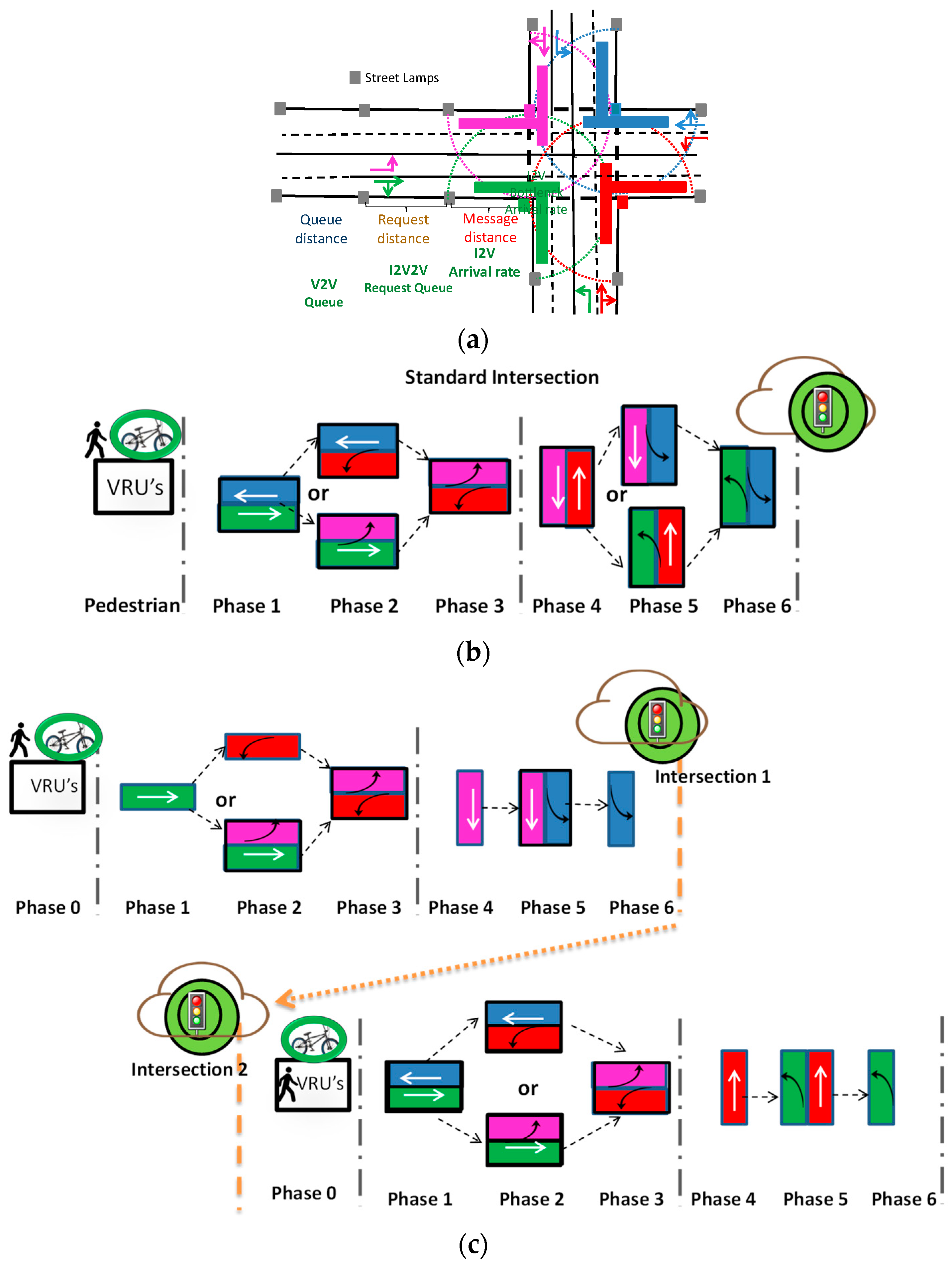
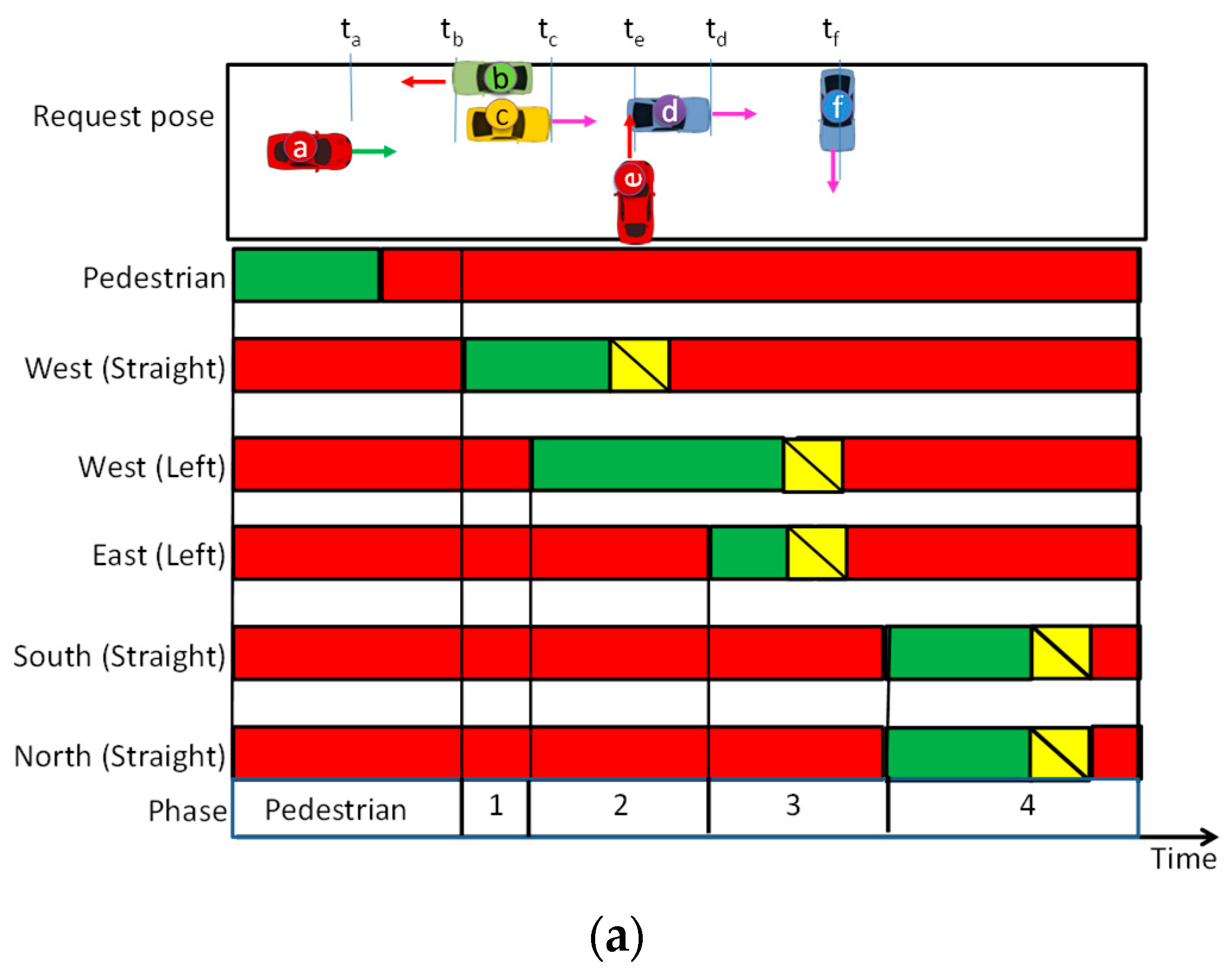
4.4. Traffic Signal Phasing: V2X Communication
Based on the simulated traffic scenario (
Figure 2) and utilizing V-VLC request/response messages, a phasing diagram was drawn, for functional areas with two-way–two-way four-legged (
Figure 9a) and split (
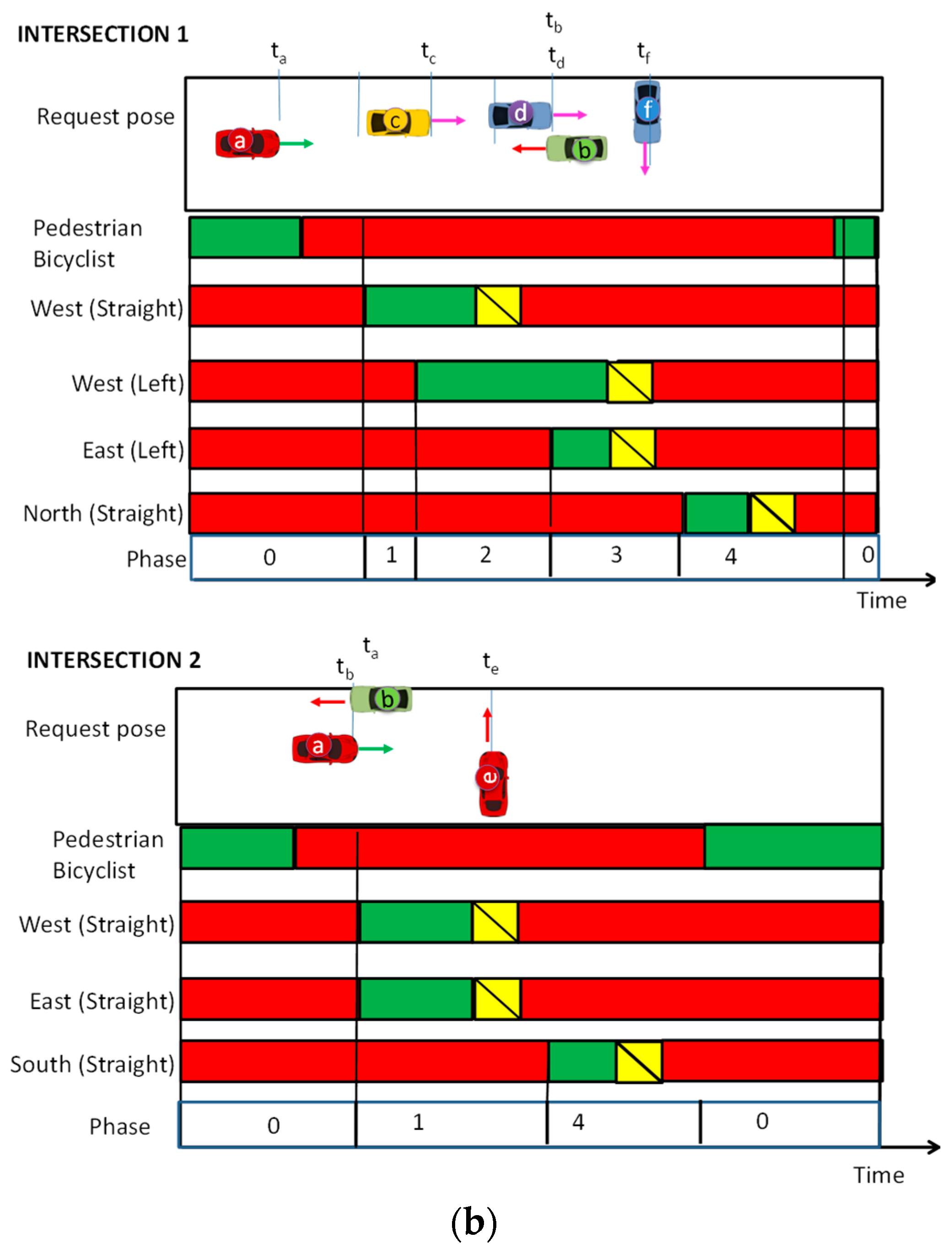
Figure 9b) intersections.
Traffic volumes that arrive at the intersection are the same in both. Here, the traffic controller uses request and response messages, from vehicles a, b, c, d, e and f, fusing the self-localizations qi (t) with their space relative poses qij (t) to generate phase durations appropriate to accommodate the demand on each cycle. Each driving vehicle is assigned an individualized time to the request (t) to enter the intersection, and t[x] is the request time of vehicle x with their pose representations.
Results show five different phases for the four-legged intersection: the pedestrian phase, Phase 1 (W straight flow), Phase 2 (W straight and left flows), Phase 3 (W and E left flows), and Phase 4 (N and S straight flows) as shown in
Figure 9a. In
Figure 9b, for the split intersection, the phasing flow for both crossroads are visualized: Intersection 1: Phases 0, pedestrian/bicyclist phase, Phase 1 (W straight flow), Phase 2 (W straight and left flows), Phase 3 (W and E left flows), and Phase 4 (N straight flow); Intersection 2: Phases 0, pedestrian/bicyclist phase, Phase 1 (W and east straight flows), and Phase 4 (S and right-turn approach flow). The exclusive pedestrian and bicyclist stage, “Walk” interval begins in both at the end of Phase 5.
From a capacity point of view, in a four-legged intersection, it is more efficient if vehicle
c is given access at
t′
c before vehicle
b, at
t′
b to the intersection and vehicle
d is given access at
t′
d before vehicle
e, at
t′
e then, forming a west left turn of set of vehicles (platoon) before giving way to the fourth phase (north and south conflicting flows), as stated in
Figure 9a. The speed of vehicle
e was reduced, keeping a safe distance between vehicle
e and vehicle
d. So, vehicle
b approaches the intersection after having asked permission to cross it and only receives authorization when the vehicle
a has left the intersection (end of Phase 2). Then, Phase 3 begins with vehicle
b heading to the intersection (W) (pose red) while vehicle
a follows its destination towards E (pose green). In the split intersection, the conventional four-legged intersection was replaced by two separate intersections (
Figure 9b). The main benefit was to improved safety, since it separates potential conflict points where vehicles, pedestrians, and bicyclists may cross paths. The separation of traffic flow on the north/south street allows Intersection 1 to handle a greater volume of traffic and operate with less delay. The pedestrian Phase will begin early and the number of phases in Intersection 2 was reduced. The wait times are shorter because fewer vehicle traffic signal phases means less time stopping at the intersections.
Additionally, through synchronization of the two signalized intersections, the corridor travel times is improved on both the major and side streets. Results show that the vehicles’ arrival is controlled and scheduled to cross the intersections in order to reduce traffic delay. The pose analysis is also used to allocate delays between left turns and forward movements. As a final remark, traffic light split coordination using the V-VLC request-response concept facilitates traffic circulation, promoting smooth movement along the network, forming platoons with efficient speeds, preventing the formation of queues, avoiding congestion and delays. This is also an effective way to reduce excessive fuel consumption and preserve the environment through minimal air pollution. To evolve towards real implementation, the performance of the V-VLC system still needs improvement, namely the distance between conflicting vehicles along with the trajectories of other opposing vehicles should also be monitored and optimized.
4.5. Queuing System: Dynamic Traffic Signal Phasing
A highly congested traffic scenario will be strongly connected. To determine the delay, the number of vehicles queuing in each cell at the beginning and end of the green time is determined by V2V2I observation, as illustrated in
Figure 10.
The same four traffic flows were considered. One is coming from west (W) but with seven vehicles approaching the crossroad: five ai vehicles with straight movement and three ci vehicles with left turn only. In the second flow, three bi vehicles from east (E) approach the intersection with left turn only. In the third flow, e vehicle, oncoming from south (S), has right-turn approach. Finally, in the fourth flow, f vehicle coming from north goes straight. Road request and response segments, offer a binary (turn left/straight or turn right) choice. According to the simulated scenario, each car represents a percentage of traffic flow. We have assumed that the intersection is approached by 540 cars per hour, of which 80 percent are coming from the east or west. Then, 50% of cars will turn left or right at the intersection and the other 50% will continue straight. There is only one episode per scenario and the cars cycle in the same order every time.
In the PoC, we have assumed that a1, b1, and a2, make up the top three requests, followed by b2, a3, and c1 in the fourth, fifth and sixth places, respectively. In the seventh, eighth and ninth request places are b3, e and a3, respectively, followed in tenth place by c2. The penultimate request is a5, and the last one is f. So, ta1 < tb1 < ta2 < tb2 < ta3 < tc1 < tb3 < te < ta4 < tc2 < ta5 < tf.
The following parameters are therefore needed to model the queuing system: The initial arrival time (t0) and velocity (v) in each the occupied section. The initial time is defined as the time when the vehicles leave the previous section (queue, request or message distances) and move along the next section, qi (t, t′). The service time is calculated using vehicle speed and distance of the section. The number of service units or resources is determined by the capacity of the section, n(qi (x, y, δ, t)) and vehicle speed which depends on the number of request services, and on the direction of movement along the lane qi (x, y, δ, t). To each driving Vehicle, xi, is assigned the unique time at which it must enter the intersection, t″[xi].
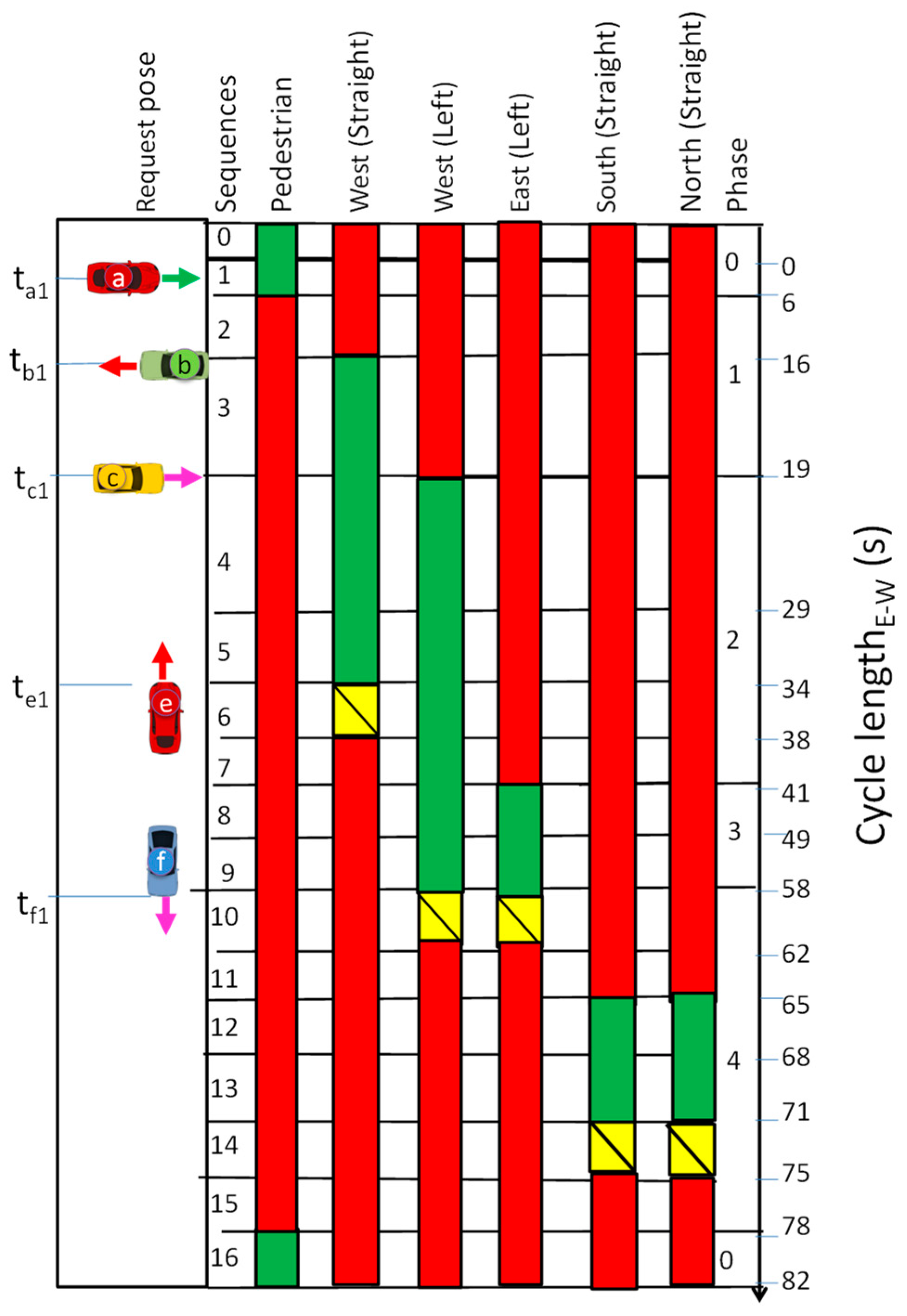
The phase flow of the PoC intersection is shown in
Figure 11 according to the phasing diagram. In this diagram, the cycle length is composed of 5 of the 7 phases contemplated (see
Figure 5a) and divided in 16 time sequences. The exclusive pedestrian phase contains the “
0”, “
1” and “
16” sequences. The cycle’s top synchronism starts with sequence “
1”. The first, second, third, and fourth phases contain sequences between “
2” and “
15” and control traffic flow.
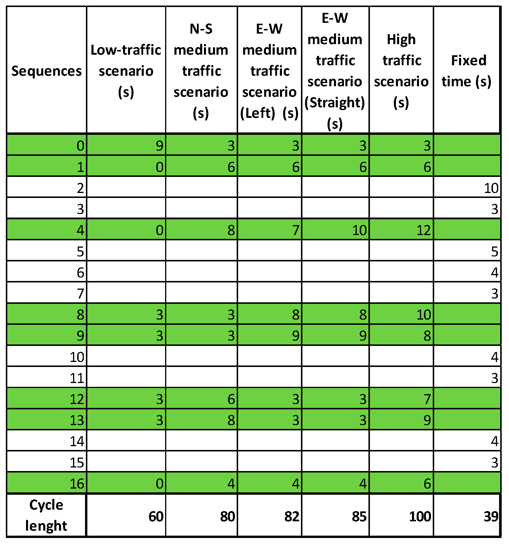
The matrix of states allows the user to view, enter, or modify the division of an intersection into states, as shown in
Figure 12.
The matrix shows the durations of the states for a given cycle. It is important to note that each element in this matrix represents how the light is lit for each state of the traffic light (if it is selected, then the light is green). Columns represent the duration of the states in the different arms of the intersection, from cycle minimum [fluid traffic] to cycle maximum [dense traffic]. For a medium traffic scenario, three distinct cycles are considered based on the higher volume traffic in the request directions (N-S, W-E straight or left). The column on the right of the matrix is called the column of fixed times. A fixed time is filled in when a state has the same duration for all the cycles of the lighting plan. The durations of movable states can be entered for any state at a dynamic time. It is possible for the IM to execute the following operations based on the information in the request: modifies the durations of the cycle; enters the fixed times; changes the durations of states with the transportable from any state at a dynamic time; and modifies the intersection coordination offset, depending on the request information.
The PoC assumes that all the leaders approach the intersection with similar velocities at different times (
Figure 11). Vehicle
a1 was the first to request to cross the intersection and informed IM about its position and also that four others follow it at their positions with their speeds. Phase 1, sequence 3, therefore, begins at
t′a1. Vehicle
b1 requests access later and includes the mappings of its two followers in its request. As the order to cross conflicts with
ai movement, he and his followers will pile up on the stop line increasing the total waiting time of the
bi cars. The fourth sequence is an adaptive sequence (
Figure 12). Due to the presence of a medium E-W traffic scenario, the IM extends the green time in order to accommodate the passage of all the
ai followers as well as the simultaneous passage of the arriving
ci (
Figure 8). From a capacity point of view, it is more efficient if vehicle
c1 is given access (Phase 2) before vehicle
bi, and vehicle
c2 is given access before vehicle
e, forming a west left turn of set of vehicles (platoon) before giving way to the fourth phase with north and south conflicting flows, as stated in
Figure 5. Meanwhile, the speed of vehicle
e was reduced, increasing the total accumulated time in the S-N arm.
Adaptive sequences 8 and 9 kick off Phase 3 (
Figure 11) and the sequence times will be adjusted according to the variation of
rt for the left turn of the
bi cars. A new phase, Phase 4, begins and includes two adaptive sequences, sequence 12 and 13. Their time intervals will be as short as possible, which will free up capacity in the cycle for the E-W flows that are heavily loaded. Taking into account the accumulated total waiting time in each arm, an 85 s cycle is recommended for this type of flow. The times associated with each sequence can be visualized in
Figure 11.
So, the real-time detection of the spatiotemporal data based on urban road network traffic status can provide rich and high-quality basic data and fine-grained assessment of control effects for traffic control.


