
Self-Healing Coatings Consisting of an Outer Electrodeposited Epoxy Resin Layer and an Inner Porous Anodic Oxide Layer with Healing Agents for the Corrosion Protection of Al Alloys
Abstract
:1. Introduction
Healing Agent
(Diisocyanate)
OCN-R-NCO + H2N-R-NH2 → -CONH-R-NH-
2. Materials and Methods
2.1. Formation of Self-Healing Electrodeposition Coating
2.2. Scratching of Coating Films with Indenters and Freezing Treatments
2.3. Evaluation of Corrosion Protection of Damaged Specimens with Self-Healing Coating
3. Results
3.1. Healing Behavior of Self-Healing Coatings after Damaging with 50° and 120° Tip Angle Indenters
3.2. Corrosion Behavior of Self-Healing Coating during Immersion in Cu2+/Cl− Solution after Scratching with 50° Tip Angle Indenter
 ), self-healing coating (
 ), and self-healing coating with freezing (
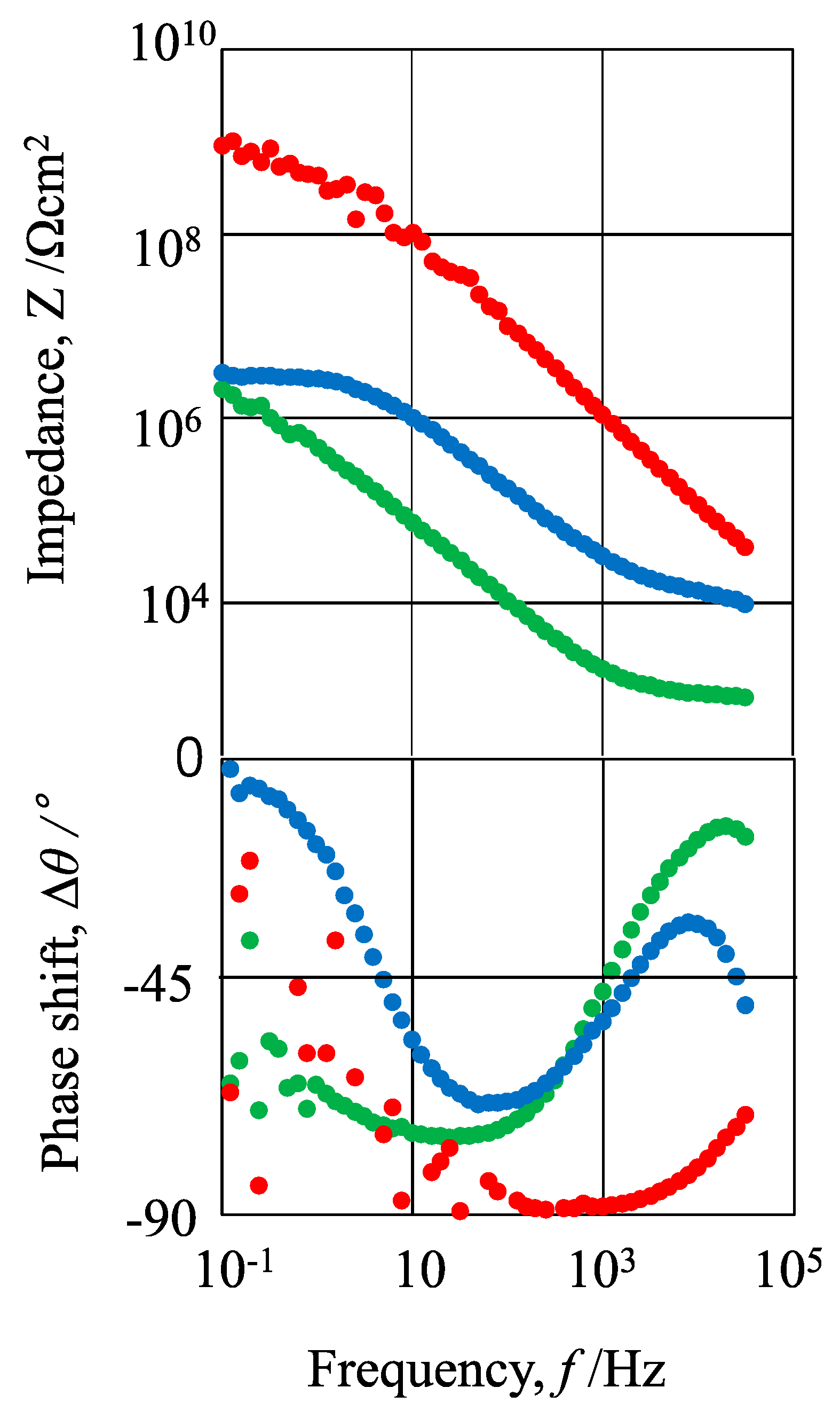
 ). All the curves were measured after scratching with a 50° tip angle indenter.) and the self-healing coating with freezing () had a linear relationship with a slope of −1 between 10 and 104 Hz, and the Z values for the self-healing coating were the same as those for the self-healing coating with freezing between 10 and 104 Hz. The plot of log Z vs. log f for the normal coating () had a flatter slope than −1, and the Z values were much smaller than those of the self-healing coatings with/without freezing. The Δθ values on the three kinds of specimens decreased with increasing f and then increased with increasing f, passing through a minimum. The minimum values of Δθ were almost −90° for the self-healing coatings with/without freezing and −60° for the normal coating. The data for the self-healing coating () and the self-healing coating with freezing () showed an appreciable scattering between 0.1 and 1 Hz, and this was due to high impedances.
3.3. Corrosion Behavior of Self-Healing Coating Film after Damaging with 120° Tip Angle Indenter
), self-healing coating, () and self-healing coating
with freezing () after damaging with a 120° tip angle indenter. As can be seen
in this figure, the plot of log Z vs. log f for all the specimens
had a linear relationship between 10 and 1000 Hz. The relationship for the
specimen covered with the self-healing coating had a slope of almost −1, but
the relationships for the specimens covered with the normal coating and self-healing
coating with freezing had slopes less than −1. The Z values between 10
and 1000 Hz for the three kinds of specimens were in the following order:4. Discussion
4.1. Analysis of the EIS Data of the Specimens Covered with Normal Coating and Self-Healing Coating after Damaging
4.2. Effects of Freezing Treatments and the Tip Angle of Indenters on Corrosion Protection of the Self-Healing Coating
5. Conclusions
Author Contributions
Funding
Data Availability Statement
Conflicts of Interest
Appendix A

References
- Vural, M.; Akkus, A. On the resistance spot weldability of galvanized interstitial free steel sheets with austenitic stainless steel sheets. J. Mater. Process. Technol. 2004, 153–154, 1–6. [Google Scholar] [CrossRef]
- Fujita, S.; Mizuno, D. Corrosion and corrosion test methods of zinc coated steel sheets on automobiles. Corros. Sci. 2007, 49, 211–219. [Google Scholar] [CrossRef]
- Mei, L.; Chen, G.; Jin, X.; Zhang, Y.; Wu, Q. Research on laser welding of high-strength galvanized automobile steel sheets. Opt. Lasers Eng. 2009, 47, 1117–1124. [Google Scholar] [CrossRef]
- Miller, W.S.; Zhuang, L.; Bottema, J.; Wittebrood, A.J.; De Smet, P.; Haszler, A.; Vieregge, A. Recent development in aluminium alloys for the automotive industry. Mater. Sci. Eng. 2000, 280, 37–49. [Google Scholar] [CrossRef]
- Lee, S.H.; Saito, Y.; Sakai, T.; Utsunomiya, H. Microstructures and mechanical properties of 6061 aluminum alloy processed by accumulative roll-bonding. Mater. Sci. Eng. 2002, 325, 228–235. [Google Scholar] [CrossRef]
- Ozturk, F.; Sisman, A.; Toros, S.; Kilic, S.; Picu, R.C. Influence of aging treatment on mechanical properties of 6061 aluminum alloy. Mater. Des. 2010, 31, 972–975. [Google Scholar] [CrossRef]
- Martínez-Viademonte, M.P.; Abrahami, S.T.; Hack, T.; Burchardt, M.; Terryn, H. A Review on Anodizing of Aerospace Aluminum Alloys for Corrosion Protection. Coating 2020, 10, 1106. [Google Scholar] [CrossRef]
- Yanagimoto, H.; Saito, K.; Okuyama, H.; Takahashi, H.; Chiba, M. Changes in the structure and corrosion protection ability of porous anodic oxide films on pure Al and Al alloys by pore sealing treatment. Materials 2022, 15, 8544. [Google Scholar] [CrossRef] [PubMed]
- Atz-Dick, P.; Konrath, A.; Melo, Y.R.; Ratke, C.; Dick, L.F.P. Aluminum anodizing with simultaneous silanization for increased hydrophobicity and corrosion protection. Appl. Surf. Sci. 2022, 593, 153392. [Google Scholar] [CrossRef]
- Titu, A.M.; Sandor, R.-N.; Pop, A.B. Research on the Influence of Coating Technologies on Adhesion Anti-Corrosion Layers in the Case of Al7175 Aluminum Alloy. Coatings 2023, 13, 1054. [Google Scholar] [CrossRef]
- Dehri, I.; Erbil, M. The effect of relative humidity on the atmospheric corrosion of defective organic coating materials: An EIS study with a new approach. Corros. Sci. 2000, 42, 969–978. [Google Scholar] [CrossRef]
- Khramov, A.N.; Voevodin, N.N.; Balbyshev, V.N.; Donley, M.S. Hybrid organo-ceramic corrosion protection coatings with encapsulated organic corrosion inhibitors. Thin Solid Films 2004, 447–448, 549–557. [Google Scholar] [CrossRef]
- Zhong, C.; Tang, X.; Cheng, Y.F. Corrosion of steel under the defected coating studied by localized electrochemical impedance spectroscopy. Electrochim. Acta 2008, 53, 4740–4747. [Google Scholar] [CrossRef]
- Dong, C.F.; Fu, A.Q.; Li, X.G.; Cheng, Y.F. Localized EIS characterization of corrosion of steel at coating defect under cathodic protection. Electrochim. Acta 2008, 54, 628–633. [Google Scholar] [CrossRef]
- Tavandashti, N.P.; Ghorbani, M.; Shojaei, A.; Mol, J.M.C.; Terryn, H.; Baert, K.; Gonzalez-Garcia, Y. Inhibitor-loaded conducting polymer capsules for active corrosion protection of coating defects. Corros. Sci. 2016, 112, 138–149. [Google Scholar] [CrossRef]
- White, S.R.; Sottos, N.R.; Geubelle, P.H.; Moore, J.S.; Kessler, M.R.; Sriram, S.R.; Brown, E.N.; Viswanathan, S. Autonomic healing of polymer composites. Nature 2001, 409, 794–797. [Google Scholar] [CrossRef] [PubMed]
- Ma, L.; Wang, J.; Zhang, D.; Huang, Y.; Huang, L.; Wang, P.; Qian, H.; Lic, X.; Terryn, H.A.; Mol, J.M.C. Dual-action self-healing protective coatings with photothermal responsive corrosion inhibitor nanocontainers. Chem. Eng. J. 2021, 404, 127118. [Google Scholar] [CrossRef]
- Chiba, M.; Yamada, C.; Okuyama, H.; Sugiura, M.; Pletincx, S.; Verbruggen, H.; Hyono, A.; De Graeve, I.; Terryn, H.; Takahashi, H. Development of novel surface treatments for corrosion protection of aluminum: Self-repairing coatings. Corros. Rev. 2018, 36, 55–64. [Google Scholar] [CrossRef]
- Chiba, M.; Tsuji, Y.; Takada, R.; Eguchi, Y.; Takahashi, H. Formation of Self-Healing Organic Coatings for Corrosion Protection of Al Alloys by Dispersion of Spherical and Fibrous Capsules. Materials 2023, 16, 3018. [Google Scholar] [CrossRef] [PubMed]
- Yang, J.; Keller, M.W.; Moore, J.S.; White, S.R.; Sottos, N.R. Microencapsulation of Isocyanates for Self-Healing Polymers. Macromolecules 2008, 41, 9650–9655. [Google Scholar] [CrossRef]
- Sondari, D.; Septevani, A.A.; Randy, A.; Triwulandari, E. Polyurethane microcapsule with glycerol as the polyol component for encapsulated self healing agent. Int. J. Eng. Technol. 2010, 2, 466–471. [Google Scholar]
- Hirasawa, K.; Tomioka, Y.; Kawamura, M.; Hyono, A.; Chiba, M. Self-healing Coating by Using Pore of Porous Film Formed on Al Alloy Anodized and Effect of Pore-size on Self-healing Property of Coating. Zair.-Kankyo 2022, 71, 63–69. [Google Scholar] [CrossRef]
- Takada, R.; Hirasawa, K.; Chiba, M. Self-healing Coating by Using Pore of Porous Film Formed on Al Alloy Anodized and Effect of Pore-Widening Treatment on Corrosion Protection. Zair.-Kankyo 2022, 71, 300–307. [Google Scholar] [CrossRef]
- Tsangaraki-Kaplanoglou, I.; Theohari, S.; Dimogerontakis, T.; Wang, Y.-M.; Kuo, H.-H.; Kia, S. Effect of alloy types on the anodizing process of aluminum. Surf. Coat. Technol. 2006, 200, 2634–2641. [Google Scholar] [CrossRef]
- Zaraska, L.; Sulka, G.D.; Szeremeta, J.; Jaskuła, M. Porous anodic alumina formed by anodization of aluminum alloy (AA1050) and high purity aluminum. Electrochim. Acta 2010, 55, 4377–4386. [Google Scholar] [CrossRef]
- Oh, J.; Thompson, C.V. The role of electric field in pore formation during aluminum anodization. Electrochim. Acta 2011, 56, 4044–4051. [Google Scholar] [CrossRef]
- Runge, J.M. Anodizing for Design and Function. J. Mater. Sci. Nanotechnol. 2011, 1, 1. [Google Scholar]
- Roslyakov, I.V.; Gordeeva, E.O.; Napolskii, K.S. Role of Electrode Reaction Kinetics in Self-Ordering of Porous Anodic Alumina. Electrochim. Acta 2017, 241, 362–369. [Google Scholar] [CrossRef]
- Kikuchi, T.; Akiya, S.; Kunimoto, K.; Suzuki, R.O.; Natsui, S. Photoluminescence from Anodic Aluminum Oxide Formed via Etidronic Acid Anodizing and Enhancing the Intensity. Mater. Trans. 2020, 61, 1130–1137. [Google Scholar] [CrossRef]
- Buruberri, L.H.; Senff, L.; Seabra, M.P.; Labrincha, J.A. Effect of Al anodizing waste on the final properties of porous geopolymers. Constr. Build. Mater. 2020, 263, 120160. [Google Scholar] [CrossRef]
- Itagaki, M. Denkikagaku-Inpidansu-Ho, 2nd ed.; Maruzen-Shuppan: Tokyo, Japan, 2011; pp. 53–86. [Google Scholar]
- Xie, C.; Li, H.; Zhou, X.; Sun, C. Corrosion behavior of cold sprayed pure zinc coating on magnesium. Surf. Coat. Technol. 2019, 374, 797–806. [Google Scholar] [CrossRef]
- Liu, J.; Lu, Z.; Zhang, L.; Li, C.; Ding, R.; Zhao, X.; Zhang, P.; Wang, B.; Cui, H. Studies of corrosion behaviors of a carbon steel/copper-nickel alloy couple under epoxy coating with artificial defect in 3.5 wt.% NaCl solution using the WBE and EIS techniques. Prog. Org. Coat. 2020, 148, 105909. [Google Scholar] [CrossRef]
- Gaona-Tiburcio, C.; Montoya-Rangel, M.; Cabral-Miramontes, J.A.; Estupiñan-López, F.; Zambrano-Robledo, P.; Cruz, R.O.; Chacón-Nava, J.G.; Baltazar-Zamora, M.A.; Almeraya-Calderón, A. Corrosion Resistance of Multilayer Coatings Deposited by PVD on Inconel 718 Usin hemical Impedance Spectroscopy Technique. Coatings 2020, 10, 521. [Google Scholar] [CrossRef]


 ), self-healing coating (), and self-healing coating with freezing (). All the curves were measured after scratching with 50° tip angle indenters.
), self-healing coating (), and self-healing coating with freezing (). All the curves were measured after scratching with 50° tip angle indenters.
), self-healing coating (), and self-healing coating with freezing (). All the curves were measured after scratching with 50° tip angle indenters.
 ), self-healing coating (), and self-healing coating with freezing (). All the curves were measured after scratching with 120° tip angle indenters.
), self-healing coating (), and self-healing coating with freezing (). All the curves were measured after scratching with 120° tip angle indenters.
), self-healing coating (), and self-healing coating with freezing (). All the curves were measured after scratching with 120° tip angle indenters.


Disclaimer/Publisher’s Note: The statements, opinions and data contained in all publications are solely those of the individual author(s) and contributor(s) and not of MDPI and/or the editor(s). MDPI and/or the editor(s) disclaim responsibility for any injury to people or property resulting from any ideas, methods, instructions or products referred to in the content. |
© 2023 by the authors. Licensee MDPI, Basel, Switzerland. This article is an open access article distributed under the terms and conditions of the Creative Commons Attribution (CC BY) license (https://creativecommons.org/licenses/by/4.0/).
Share and Cite
Takada, R.; Hirasawa, K.; Takahashi, H.; Chiba, M. Self-Healing Coatings Consisting of an Outer Electrodeposited Epoxy Resin Layer and an Inner Porous Anodic Oxide Layer with Healing Agents for the Corrosion Protection of Al Alloys. Corros. Mater. Degrad. 2023, 4, 516-527. https://doi.org/10.3390/cmd4030027
Takada R, Hirasawa K, Takahashi H, Chiba M. Self-Healing Coatings Consisting of an Outer Electrodeposited Epoxy Resin Layer and an Inner Porous Anodic Oxide Layer with Healing Agents for the Corrosion Protection of Al Alloys. Corrosion and Materials Degradation. 2023; 4(3):516-527. https://doi.org/10.3390/cmd4030027
Chicago/Turabian StyleTakada, Rin, Kota Hirasawa, Hideaki Takahashi, and Makoto Chiba. 2023. "Self-Healing Coatings Consisting of an Outer Electrodeposited Epoxy Resin Layer and an Inner Porous Anodic Oxide Layer with Healing Agents for the Corrosion Protection of Al Alloys" Corrosion and Materials Degradation 4, no. 3: 516-527. https://doi.org/10.3390/cmd4030027