
Investigation on the Effect of a Chromium-Free Sealing Treatment for the Corrosion Resistance of AA2198-T851 after Tartaric Sulphuric Anodizing (TSA)
 , and
, and
Abstract
:1. Introduction
2. Materials and Methods
3. Results
4. Discussion
5. Conclusions
Author Contributions
Funding
Acknowledgments
Conflicts of Interest
References
- MacKenzie, D.S.; Totten, G.E. Handbook of Aluminum, 1st ed.; Totten, G.E., MacKenzie, D.S., Eds.; CRC Press: Boca Raton, FL, USA, 2003; ISBN 9780203912607. [Google Scholar]
- Queiroz, F.M.; Magnani, M.; Costa, I.; de Melo, H.G. Investigation of the Corrosion Behaviour of AA 2024-T3 in Low Concentrated Chloride Media. Corros. Sci. 2008, 50, 2646–2657. [Google Scholar] [CrossRef]
- Noble, B.; Thompson, G.E. Ti (Al2CuLi) Precipitation in Aluminium–Copper–Lithium Alloys. Metal. Sci. J. 1972, 6, 167–174. [Google Scholar] [CrossRef]
- De Sousa Araujo, J.V.; Donatus, U.; Queiroz, F.M.; Terada, M.; Milagre, M.X.; de Alencar, M.C.; Costa, I. On the Severe Localized Corrosion Susceptibility of the AA2198-T851 Alloy. Corros. Sci. 2018, 133, 132–140. [Google Scholar] [CrossRef]
- Hatamleh, O.; Hill, M.; Forth, S.; Garcia, D. Fatigue Crack Growth Performance of Peened Friction Stir Welded 2195 Aluminum Alloy Joints at Elevated and Cryogenic Temperatures. Mater. Sci. Eng. A 2009, 519, 61–69. [Google Scholar] [CrossRef]
- Prasad, N.E.; Gokhale, A.A.; Rao, P.R. Mechanical Behaviour of Aluminium-Lithium Alloys. Sadhana 2003, 28, 209–246. [Google Scholar] [CrossRef]
- Warner, T. Recently-Developed Aluminium Solutions for Aerospace Applications. Mater. Sci. Forum. 2006, 519–521, 1271–1278. [Google Scholar] [CrossRef]
- Sanders, T.H.; Starke, E.A., Jr. Aluminum-Lithium Alloys. In Proceedings of the 2nd International Conference on Aluminum-Lithium Alloys, Monterey, CA, USA, 12 April 1983. [Google Scholar]
- Sanders, T.H., Jr.; Starke, E.A., Jr. Aluminum-Lithium Alloys. In Proceedings of the 1st International Aluminum-Lithium Alloys, Stone Mountain, CA, USA, 1 December 1980. [Google Scholar]
- Rioja, R.J.; Liu, J. The Evolution of Al-Li Base Products for Aerospace and Space Applications. Metall. Mater. Trans. A Phys. Metall. Mater. Sci. 2012, 43, 3325–3337. [Google Scholar] [CrossRef]
- Garrard, W. Corrosion Behavior of Aluminum-Lithium Alloys. Corros. Sci. 1994, 50, 215–225. [Google Scholar] [CrossRef]
- Semenov, A.M. Effect of Mg Additions and Thermal Treatment on Corrosion Properties of Al–Li–Cu-Base Alloys. Prot. Met. 2001, 37, 126–131. [Google Scholar] [CrossRef]
- Ambat, R.; Dwarakadasa, E.S. The Influence of PH on the Corrosion of Medium Strength Aerospace Alloys 8090, 2091 and 2014. Corros. Sci. 1992, 33, 681–690. [Google Scholar] [CrossRef]
- Cavaliere, P.; Cabibbo, M.; Panella, F.; Squillace, A. 2198 Al–Li Plates Joined by Friction Stir Welding: Mechanical and Microstructural Behavior. Mater. Des. 2009, 30, 3622–3631. [Google Scholar] [CrossRef]
- Bello, N.; Larignon, C.; Douin, J. Long-Term Thermal Ageing of the 2219-T851 and the 2050-T84 Al-Cu Alloys. Mater. Today Commun. 2021, 29, 102834. [Google Scholar] [CrossRef]
- Bitondo, C.; Prisco, U.; Squilace, A.; Buonadonna, P.; Dionoro, G. Friction-Stir Welding of AA 2198 Butt Joints: Mechanical Characterization of the Process and of the Welds through DOE Analysis. Int. J. Adv. Manuf. Technol. 2011, 53, 505–516. [Google Scholar] [CrossRef]
- Moreto, J.; Gamboni, O.; Rocha, L. Corrosion Behavior of Al and Al-Li Alloys Used as Aircraft Materials. Corrosão E Protecção De Mater. 2012, 31, 60–64. [Google Scholar]
- Sepe, R.; Giannella, V.; Mazza, P.; Armentani, E.; Javad Razavi, S.M.; Berto, F. Fatigue Fracture Tests on Al-Li 2198-T851 Specimens under Mixed-Mode Conditions. In Proceedings of the Procedia Structural Integrity; Elsevier: Amsterdam, The Netherlands, 2021; Volume 39, pp. 546–551. [Google Scholar]
- Yang, Y.; Bi, J.; Liu, H.; Li, Y.; Li, M.; Ao, S.; Luo, Z. Research Progress on the Microstructure and Mechanical Properties of Friction Stir Welded Al–Li Alloy Joints. J. Manuf. Process. 2022, 82, 230–244. [Google Scholar] [CrossRef]
- Conde, A.; Fernández, B.J.; De Damborenea, J.J. Characterization of the SCC Behaviour of 8090 Al-Li Alloy by Means of the Slow-Strain-Rate Technique. Corros. Sci. 1998, 40, 91–102. [Google Scholar] [CrossRef] [Green Version]
- Ma, Y.; Zhou, X.; Thompson, G.E.; Curioni, M.; Hashimoto, T.; Skeldon, P.; Thomson, P.; Fowles, M. Anodic Film Formation on AA 2099-T8 Aluminum Alloy in Tartaric–Sulfuric Acid. J. Electrochem. Soc. 2011, 158, C17. [Google Scholar] [CrossRef]
- Georgoulis, D.; Charalampidou, C.M.; Alexopoulos, N.D. Corrosion Resistance of Aluminum Alloy 2198 for Different Ageing Tempers. In Proceedings of the Procedia Structural Integrity; Elsevier: Amsterdam, The Netherlands, 2021; Volume 37, pp. 941–947. [Google Scholar]
- Ferreira, M.O.A.; Gelamo, R.V.; Marino, C.E.B.; da Silva, B.P.; Aoki, I.V.; da Luz, M.S.; Alexopoulos, N.D.; Leite, N.B.; Moreto, J.A. Effect of Niobium Oxide Thin Film on the Long-Term Immersion Corrosion of the 2198-T851 Aluminium Alloy. Materialia 2022, 22, 101407. [Google Scholar] [CrossRef]
- Da Silva, R.M.P.; Milagre, M.X.; Izquierdo, J.; Betancor-Abreu, A.M.; de Oliveira, L.A.; de S. Araujo, J.V.; Antunes, R.A.; Souto, R.M.; Costa, I. Surface Finishing Effects on the Corrosion Behavior and Electrochemical Activity of 2098-T351 Aluminum Alloy Investigated Using Scanning Microelectrochemical Techniques. Mater. Charact. 2022, 191, 112130. [Google Scholar] [CrossRef]
- Da Silva, R.M.P.; Izquierdo, J.; Milagre, M.X.; de S. Araujo, J.V.; Antunes, R.A.; Souto, R.M.; Costa, I. Electrochemical Characterization of Alloy Segregation in the Near-Surface Deformed Layer of Welded Zones of an Al−Cu−Li Alloy Using Scanning Electrochemical Microscopy. Electrochim. Acta. 2022, 427, 140873. [Google Scholar] [CrossRef]
- Yu, X.; Cao, C. Electrochemical Study of the Corrosion Behavior of Ce Sealing of Anodized 2024 Aluminum Alloy. Thin Solid. Film. 2003, 423, 252–256. [Google Scholar] [CrossRef]
- Zhao, J.M.; Chen, S.L.; Huo, P. Comparative Studies on Corrosion Behaviour of Sealed Aluminium with Cerium Salt under Bidirectional Pulse Electric Field. Corros. Eng. Sci. Technol. 2012, 47, 203–208. [Google Scholar] [CrossRef]
- Song, D.; Ma, M.; Zhao, L. Study of Sealing of Anodized Aluminium in Mixed Titanium- Cerium Salt Solutions. Int. J. Electrochem. Sci. 2022, 17, 221224. [Google Scholar] [CrossRef]
- Carangelo, A.; Curioni, M.; Acquesta, A.; Monetta, T.; Bellucci, F. Application of EIS to In Situ Characterization of Hydrothermal Sealing of Anodized Aluminum Alloys: Comparison between Hexavalent Chromium-Based Sealing, Hot Water Sealing and Cerium-Based Sealing. J. Electrochem. Soc. 2016, 163, C619–C626. [Google Scholar] [CrossRef] [Green Version]
- Terada, M.; Queiroz, F.M.; Costenaro, H.; Ayusso, V.H.; Olivier, M.; Costa, I.; de Melo, H.G. Effect of Cerium Addition to a Hydrothermal Treatment on the Corrosion Protection of the Tartaric-Sulfuric Acid Anodized AA2524-T3. Corrosion 2019, 75, 1110–1117. [Google Scholar] [CrossRef]
- Terada, M.; Queiroz, F.M.; Aguiar, D.B.S.; Ayusso, V.H.; Costenaro, H.; Olivier, M.-G.; de Melo, H.G.; Costa, I. Corrosion Resistance of Tartaric-Sulfuric Acid Anodized AA2024-T3 Sealed with Ce and Protected with Hybrid Sol–Gel Coating. Surf. Coat. Technol. 2019, 372, 422–426. [Google Scholar] [CrossRef]
- Prada Ramirez, O.M.; Queiroz, F.M.; Terada, M.; Donatus, U.; Costa, I.; Olivier, M.-G.; de Melo, H.G. EIS Investigation of a Ce-Based Posttreatment Step on the Corrosion Behaviour of Alclad AA2024 Anodized in TSA. Surf. Interface Anal. 2019, 51, 1260–1275. [Google Scholar] [CrossRef]
- Milagre, M.X.; Mogili, N.V.; Donatus, U.; Giorjão, R.A.R.; Terada, M.; Araujo, J.V.S.; Machado, C.S.C.; Costa, I. On the Microstructure Characterization of the AA2098-T351 Alloy Welded by FSW. Mater. Charact. 2018, 140, 233–246. [Google Scholar] [CrossRef]
- De Sousa Araujo, J.V.; Santos Bugarin, A.D.F.; Donatus, U.; Machado, C.D.S.C.; Queiroz, F.M.; Terada, M.; Astarita, A.; Costa, I. Thermomechanical Treatment and Corrosion Resistance Correlation in the AA2198 Al–Cu–Li Alloy. Corros. Eng. Sci. Technol. 2019, 54, 575–586. [Google Scholar] [CrossRef]
- Li, F.; Zhang, L.; Metzger, R.M. On the Growth of Highly Ordered Pores in Anodized Aluminum Oxide. Chem. Mater. 1998, 10, 2470–2480. [Google Scholar] [CrossRef]
- García-Rubio, M.; de Lara, M.P.; Ocón, P.; Diekhoff, S.; Beneke, M.; Lavía, A.; García, I. Effect of Postreatment on the Corrosion Behaviour of Tartaric-Sulphuric Anodic Films. Electrochim. Acta 2009, 54, 4789–4800. [Google Scholar] [CrossRef]
- Ren, J.; Zuo, Y. The Anodizing Behavior of Aluminum in Malonic Acid Solution and Morphology of the Anodic Films. Appl. Surf. Sci. 2012, 261, 193–200. [Google Scholar] [CrossRef]
- Van der Linden, B.; Terryn, H.; Vereecken, J. Investigation of Anodic Aluminium Oxide Layers by Electrochemical Impedance Spectroscopy. J. Appl. Electrochem. 1990, 20, 798–803. [Google Scholar] [CrossRef]
- Capelossi, V.R.; Poelman, M.; Recloux, I.; Hernandez, R.P.B.; de Melo, H.G.; Olivier, M.G. Corrosion Protection of Clad 2024 Aluminum Alloy Anodized in Tartaric-Sulfuric Acid Bath and Protected with Hybrid Sol–Gel Coating. Electrochim. Acta. 2014, 124, 69–79. [Google Scholar] [CrossRef]


| Elements | Cu | Mg | Li | Si | Fe | Ti | Zr | Zn | Al |
|---|---|---|---|---|---|---|---|---|---|
| AA2198-T851 | 3.68 | 0.31 | 1.01 | 0.03 | 0.08 | 0.027 | 0.12 | 0.01 | Balance |
| AA2198-T851 Unsealed | ||||||||
|---|---|---|---|---|---|---|---|---|
| 24 h | 48 h | 72 h | 96 h | |||||
| Error (%) | Error (%) | Error (%) | Error (%) | |||||
| Rsol (Ω·cm2) | 25.21 | - | 27.68 | - | 25.11 | - | 50.39 | - |
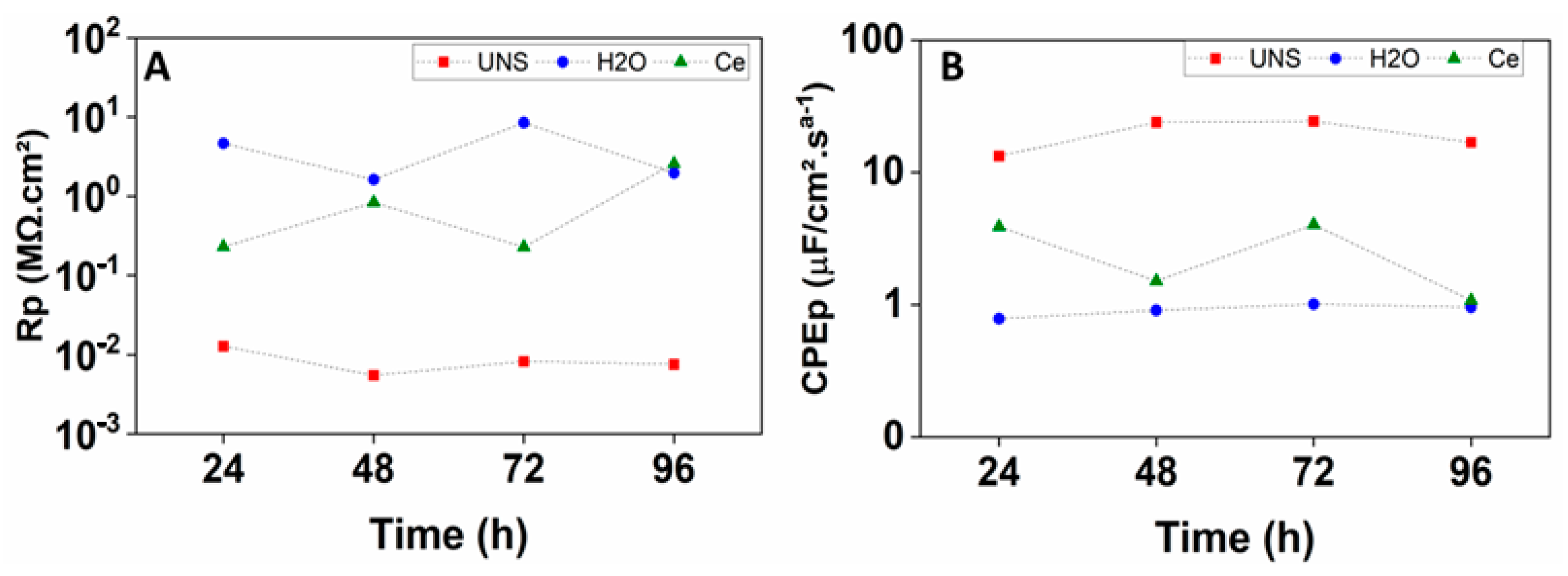
| CPEp (F/cm2·sa−1) | 1.33 × 10⁻⁵ | 2.2 | 2.39 × 10⁻⁵ | 0.7 | 2.44 × 10⁻⁵ | 1.3 | 1.69 × 10⁻⁵ | 1.7 |
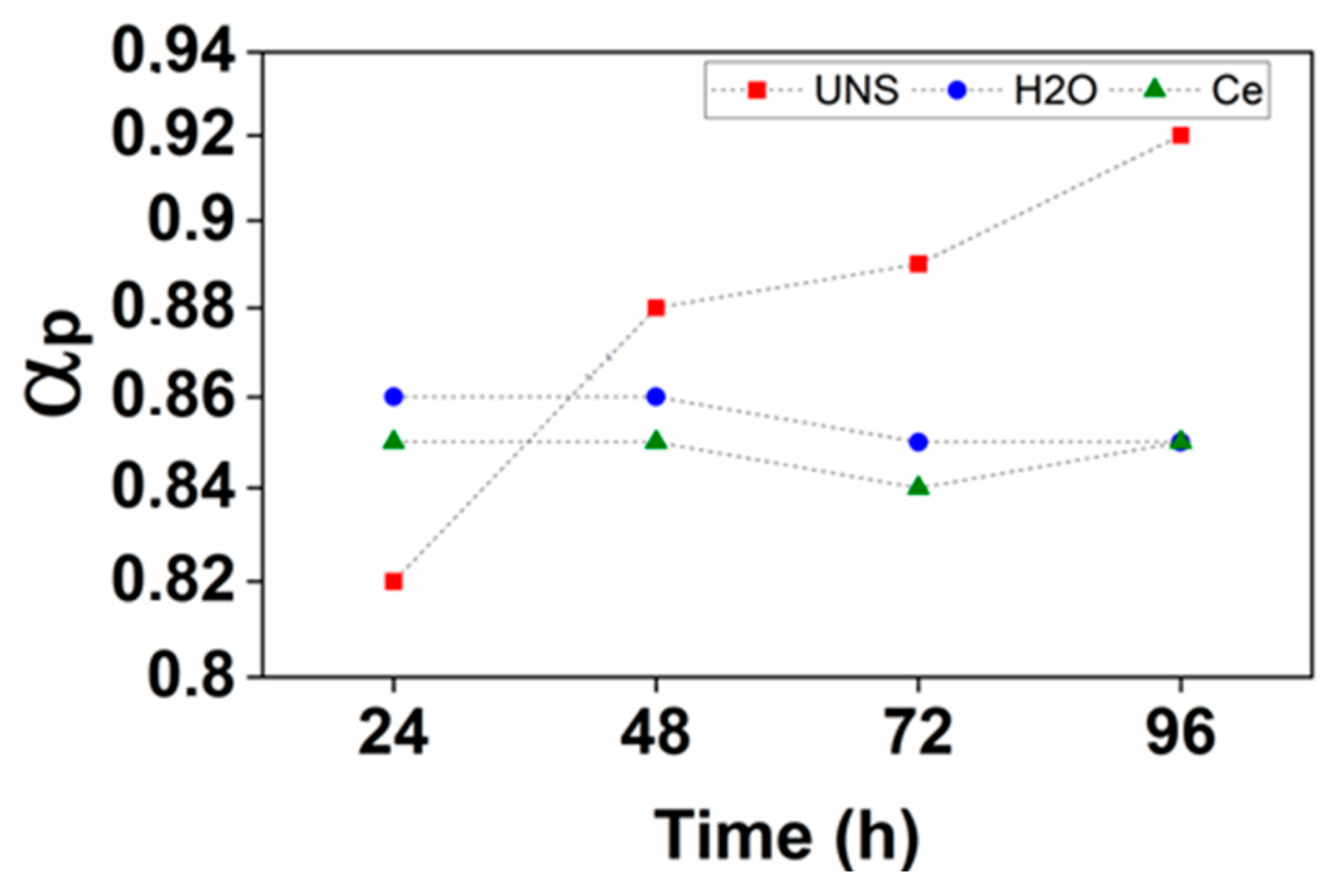
| αp | 0.82 | 0.4 | 0.88 | 0.3 | 0.89 | 0.6 | 0.92 | 0.7 |
| Rp (Ω·cm2) | 1.28 × 10⁴ | 1.4 | 5.50 × 10³ | 1.3 | 8.23 × 10³ | 1.9 | 7.57 × 10³ | 2.1 |
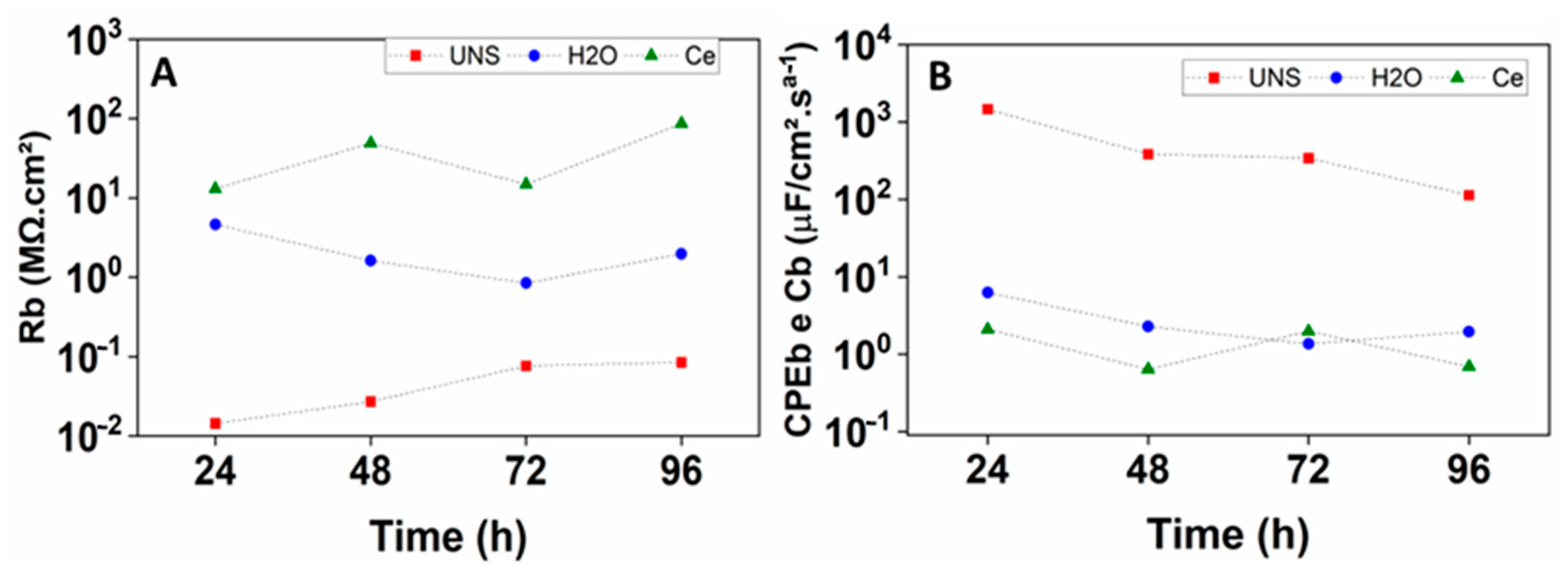
| CPEb (F/cm2·sn−1) | 1.46 × 10⁻³ | 6.4 | 3.83 × 10⁻⁴ | 2.3 | 3.40 × 10⁻⁴ | 3.3 | 1.13 × 10⁻⁴ | 1.6 |
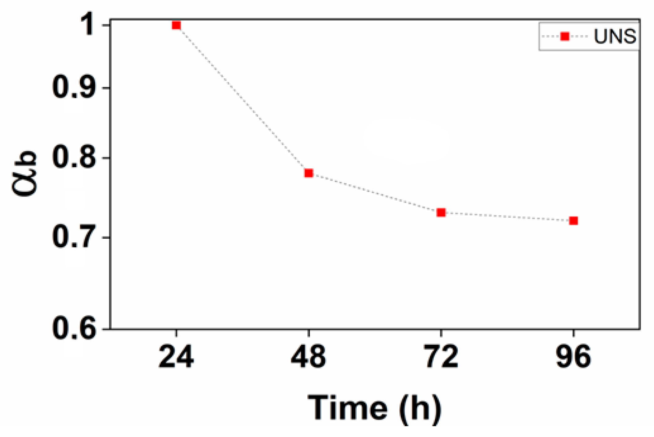
| αb | 1.0 | - | 0.78 | 1.4 | 0.73 | 1.7 | 0.72 | 0.7 |
| Rb (Ω·cm2) | 1.44 × 10⁴ | 11.7 | 2.72 × 10⁴ | 3.3 | 7.66 × 10⁴ | 10.4 | 8.45 × 10⁴ | 2.9 |
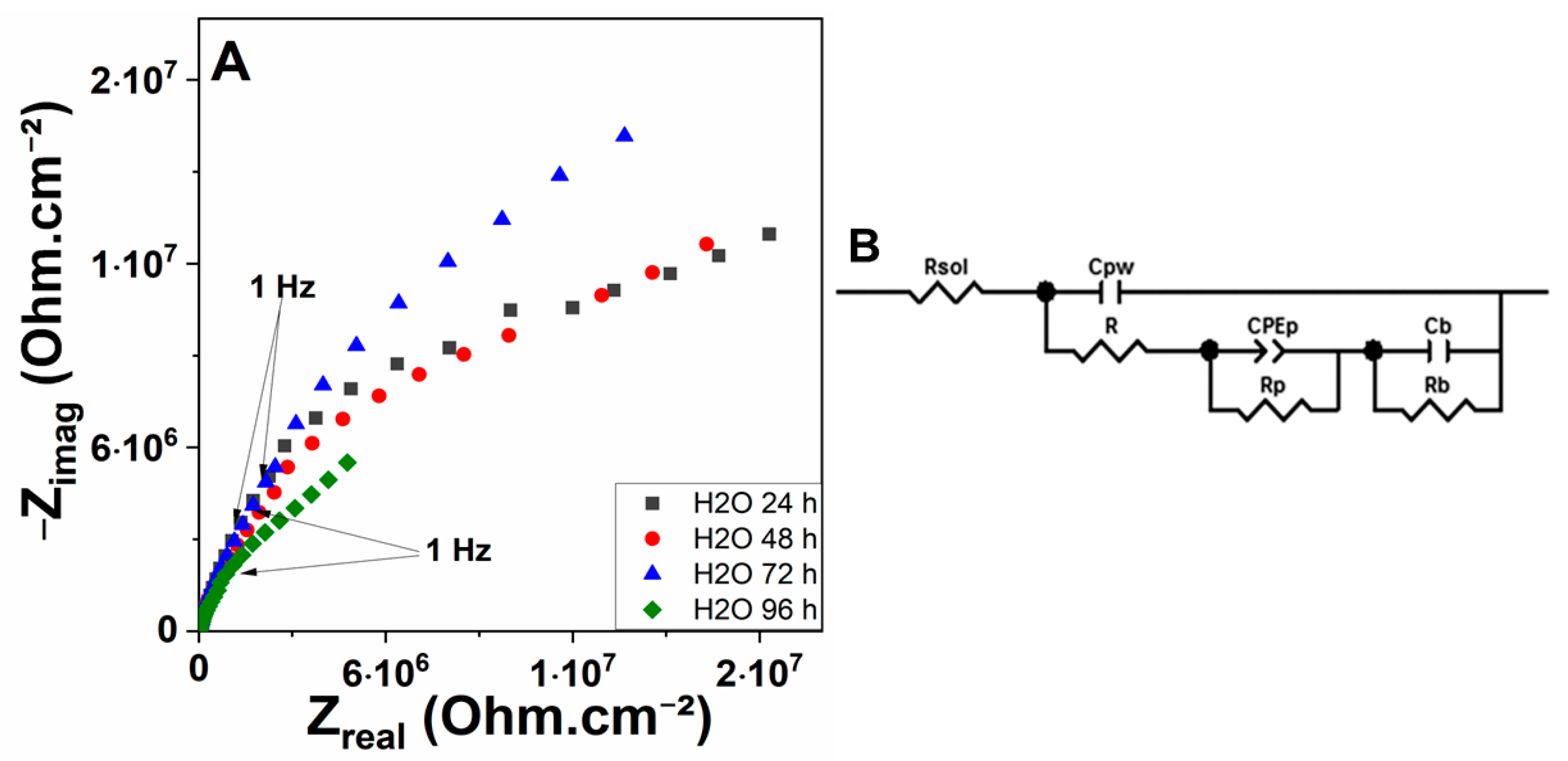
| AA2198-T851 Alloy Anodized and Sealed in Hot Water | ||||||||
|---|---|---|---|---|---|---|---|---|
| 24 h | 48 h | 72 h | 96 h | |||||
| Error (%) | Error (%) | Error (%) | Error (%) | |||||
| Rsol (Ω·cm2) | 61.82 | 7.2 | 62.82 | 13.4 | 100.1 | 4.5 | 80.65 | 5.2 |
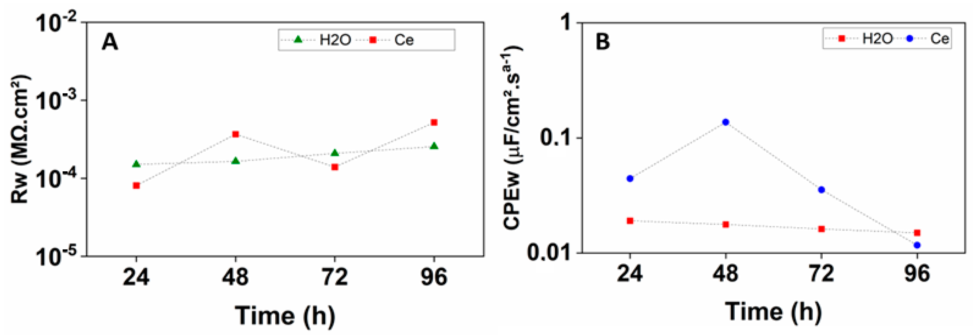
| Cpw (F/cm2) | 1.91 × 10⁻⁸ | 7.2 | 1.77 × 10⁻⁸ | 12.4 | 1.62 × 10⁻⁸ | 5.4 | 1.50 × 10⁻⁸ | 4.2 |
| R (Ω·cm2) | 150.6 | 2.4 | 164.6 | 4.2 | 208.7 | 1.9 | 255.8 | 1.7 |
| CPEp (F/cm2·sa−1) | 7.86 × 10⁻⁷ | 1.1 | 9.09 × 10⁻⁷ | 2.8 | 1.01 × 10⁻⁶ | 1.7 | 9.56 × 10⁻⁷ | 1.4 |
| αp | 0.86 | 0.2 | 0.86 | 0.5 | 0.85 | 0.3 | 0.85 | 0.3 |
| Rp (Ω·cm2) | 4.64 × 10⁶ | 2.1 | 1.62 × 10⁶ | 4.9 | 8.46 × 10⁶ | 3.3 | 1.97 × 10⁶ | 2.8 |
| Cb (F/cm2) | 6.28 × 10⁻⁶ | - | 2.29 × 10⁻⁶ | - | 1.36 × 10⁻⁶ | - | 1.95 × 10⁻⁶ | - |
| Rb (Ω·cm2) | 5.88 × 10⁶ | 17.7 | 5.71 × 10⁶ | 6.9 | 8.63 × 10⁶ | 3.2 | 1.14 × 10⁷ | 4.3 |
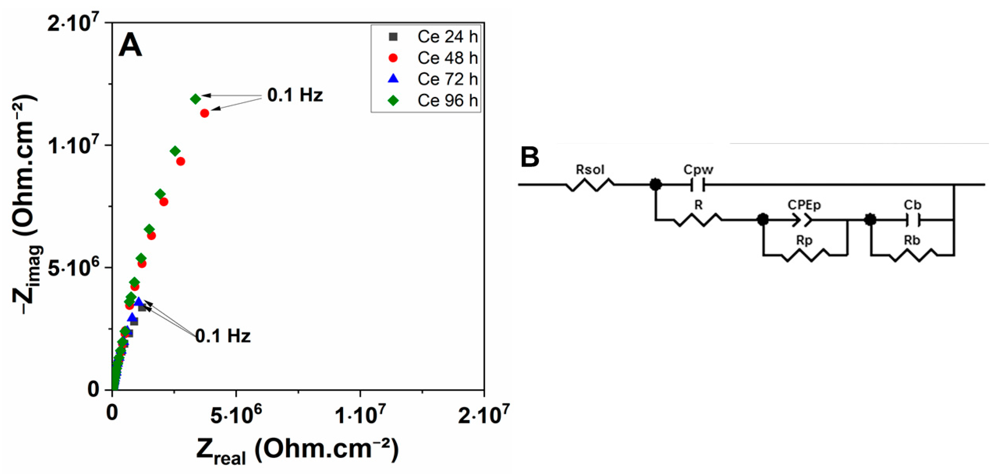
| AA2198-T851 Alloy Anodized and Sealed in Solution with Cerium Ions | ||||||||
|---|---|---|---|---|---|---|---|---|
| 24 h | 48 h | 72 h | 96 h | |||||
| Error (%) | Error (%) | Error (%) | Error (%) | |||||
| Rsol (Ω·cm2) | 28.08 | - | 125.4 | - | 33.2 | - | 141.5 | 5.2 |
| Cpw (F/cm2) | 4.44 × 10⁻⁸ | 2.0 | 1.37 × 10⁻⁷ | 1.9 | 3.55 × 10⁻⁸ | 2.0 | 1.17 × 10⁻⁸ | 4.1 |
| R (Ω·cm2) | 80.96 | 1.3 | 367.1 | 1.4 | 139.7 | 1.5 | 520.0 | 2.2 |
| CPEp (F/cm2·sa−1) | 3.89 × 10⁻⁶ | 2.4 | 1.51 × 10⁻⁶ | 2.6 | 4.04 × 10⁻⁶ | 3.5 | 1.08 × 10⁻⁶ | 3.1 |
| αp | 0.85 | 0.4 | 0.85 | 0.4 | 0.84 | 0.6 | 0.85 | 0.6 |
| Rp (Ω·cm2) | 2.31 × 10⁵ | 8.1 | 8.33 × 10⁵ | 8.7 | 2.29 × 10⁵ | 13.1 | 2.59 × 10⁶ | 9.7 |
| Cb (F/cm2) | 2.10 × 10⁻⁶ | 1.2 | 6.39 × 10⁻⁷ | 1.3 | 1.99 × 10⁻⁶ | 1.9 | 6.94 × 10⁻⁷ | - |
| Rb (Ω·cm2) | 1.31 × 10⁷ | 3.5 | 4.89 × 10⁷ | 4.3 | 1.48 × 10⁷ | 10.0 | 8.64 × 10⁷ | 13.4 |
Disclaimer/Publisher’s Note: The statements, opinions and data contained in all publications are solely those of the individual author(s) and contributor(s) and not of MDPI and/or the editor(s). MDPI and/or the editor(s) disclaim responsibility for any injury to people or property resulting from any ideas, methods, instructions or products referred to in the content. |
© 2023 by the authors. Licensee MDPI, Basel, Switzerland. This article is an open access article distributed under the terms and conditions of the Creative Commons Attribution (CC BY) license (https://creativecommons.org/licenses/by/4.0/).
Share and Cite
Queiroz, F.M.; de Fátima Santos Bugarin, A.; Ayusso, V.H.; Terada, M.; Costa, I. Investigation on the Effect of a Chromium-Free Sealing Treatment for the Corrosion Resistance of AA2198-T851 after Tartaric Sulphuric Anodizing (TSA). Corros. Mater. Degrad. 2023, 4, 331-344. https://doi.org/10.3390/cmd4020017
Queiroz FM, de Fátima Santos Bugarin A, Ayusso VH, Terada M, Costa I. Investigation on the Effect of a Chromium-Free Sealing Treatment for the Corrosion Resistance of AA2198-T851 after Tartaric Sulphuric Anodizing (TSA). Corrosion and Materials Degradation. 2023; 4(2):331-344. https://doi.org/10.3390/cmd4020017
Chicago/Turabian StyleQueiroz, Fernanda Martins, Aline de Fátima Santos Bugarin, Victor Hugo Ayusso, Maysa Terada, and Isolda Costa. 2023. "Investigation on the Effect of a Chromium-Free Sealing Treatment for the Corrosion Resistance of AA2198-T851 after Tartaric Sulphuric Anodizing (TSA)" Corrosion and Materials Degradation 4, no. 2: 331-344. https://doi.org/10.3390/cmd4020017