1. Introduction
In the Architectural, Engineering and Construction (AEC) industry, the term Building Information Model (BIM) refers to both the digital representation of the physical and functional characteristics of an asset (as-designed or as-built), and the process of information management related to that asset [
1]. BIM must be a reliable repository for the collection, maintenance and archive of all the geometrical and information data, which is accessible on a collaborative platform where they can be shared, manipulated, extracted and updated at all times. BIM is strategic for buildings management and is specifically aimed at facilitating operational decisions during their whole lifecycle, from design to commissioning [
2].
In the last 15 years, BIM methodology was extended to the management of buildings of historical value as well, with special regard to the Archaeological, Architectural and Cultural Heritage (CH) fields [
3]. According to Murphy et al. [
4], Historical or Heritage BIM (HBIM) is the application of a BIM digitization to a CH asset for maintenance purposes. The features of HBIM are derived from BIM methodology, in particular:
- i.
HBIM is therefore an object-oriented model generation solution where architectural elements are not only represented in their geometry but also the corresponding attributes of a historical database, continuously expandable and updatable [
5];
- ii.
the semantic signification and the attribute, material, and relationship information added to the parametrised objects, developed into a BIM environment, is crucial to the HBIM model because it is intended more as a data collector rather than a geometrical representation [
6];
- iii.
the possibility of using libraries of parametric objects eases the insertion of repetitive components, and the capacity to deal with large datasets and to assign attributes of several types (i.e., images, maps, reports, or any type of digital document) to the individual geometric components of the model [
7].
Otherwise, the most important difference between BIM and HBIM is that HBIM must always match the CH requirements, based on the scopes the model has been created for [
8]. Among the complexity and diversity of these purposes (which may vary from case to case), some main requirements of HBIM could be summarized as follows, as reported in [
9]:
to reflect the exact geometry and any other anomalies available on the surface of the artefact/monument (such as deformations, irregularities, cracks, etc.);
to support information enrichment with materials properties and construction techniques analysis;
to support assessment and data interpretation, since the BIM model replicates the behaviour of the real structures;
to lead the preservation plans starting from understanding and interpreting state-of-the-art up to managing the design and decision-making process;
to prevent future damages by applying planned preservation (Long Life Cycle Management);
to deploy the knowledge transfer of enriched models among different operators;
to promote the use and re-use for dissemination purposes (MR/VR/AR).
From an organisational point of view, HBIM models should answer three main questions: “what”, “why” and “how” each element to be modelled was built [
10]. For these reasons, HBIM is often defined as “reverse engineering” [
11], based on a demanded exhaustive graphic control [
12] and reality-based models to preserve authenticity [
13]. To match these strict requirements and prior to starting the proper modelling phase, currently the AEC sector has widely adopted capture technologies [
14] for a preliminary survey of the case studies; data acquired on-site are processed into a point cloud to be used for the HBIM model and the associated digital information system.
This approach is called Scan-to-BIM, and its multidisciplinary workflow has been codified by Murphy et al. in 2009 [
15] in a set of instructions and rules about the decisions, the actions, the choices and all the general procedures to be followed at each step, from acquisition to the final model. The Scan-to-BIM allows the integration of photogrammetry and laser scanning in the BIM workflow [
16] and it can be defined as the process of capturing a physical site or space using data acquired from the air or from the ground to develop a smart model by employing BIM software [
17]. This process is essential to obtaining as-built models of historical buildings, especially when their geometrical documentation is missing or incomplete.
Within a Scan-to-BIM process, data acquisition is routinely undertaken in the less time-consuming and most efficient, non-invasive way with laser scanning or photogrammetry techniques, or a combination of both [
18]. Regardless of the method used, the resulting point cloud represents the captured surface of the entire building in its actual state of conservation, contains information about its texture, colour, and architectural morphology, and provides a scaffold upon which BIM objects are directly modelled [
19]. It must be mentioned as well that, despite the huge amount of data acquired, the point cloud doesn’t contain any information on materials and construction methods, but identifies the shapes of the objects only.
Although Scan-to-BIM is among the most used and helpful methods for obtaining reliable geometric accuracy (which is one of the two main aspects of HBIM), the modelling phase based on a point cloud is still considered to be the bottleneck of the whole process [
20]. This is mainly due to the unavailability of historical parametric object libraries and the lack of tools for managing complex and irregular architectural shapes in BIM software, which were conceived for modern buildings’ design made by standardised items. The scarce flexibility of the software tools causes a loss of accuracy and details, especially regarding the items which are different or slightly deformed from the ideal model due to limitations of the construction techniques used in the past, or structural failures. This implies the mandatory expertise of operators in creating ad-hoc specific semantics about the uniqueness of components to be implemented. Those ad-hoc specific semantics should be more exhaustive and comprehensive of the characteristics of the CH and would replace the default one available on BIM authoring tools.
The automated and semi-automated generation of parametric components with information attached, still in the early stages of development [
21], relies on feature detection in point clouds. For this reason, reproduction and placement of constructive items in their correct three-dimensional space are usually done through manual methods upon segmented 2D planes of the point cloud (i.e., the main levels and sections). Those manual methods, which still represent the most used approach in modelling, notoriously require a large amount of working time, high-performance machines and interoperability among software used for different purposes; additionally, they are subject to the operators’ sensitivity and expertise, whose knowledge and critical interpretation is pivotal and could affect the final model with errors in measurements and rendition.
Considering this scenario, this research is focused on a Scan-to-BIM-based approach applied to two medieval churches in Palermo (Italy): St. John the Baptist of the Lepers and St. John the Evangelist of the Hermits (this one was included in the UNESCO World Heritage Sites list in 2015). The choice of these two case studies is justified by their being the first churches in Sicily to be built according to the Arab-Norman style, with their architectural features (such as windows, arches, bell towers, domes, etc.) serving as a prototype for other coeval buildings related to this domination. During the modelling phase, the representation of the buildings’ constructive systems has been emphasised to constitute a comprehensive HBIM library to be used as a repository for this peculiar style and to define an overall methodology of how to approach and develop the implementation of planned conservation for similar buildings.
The paper is organized as follows: in
Section 2, there is a brief historical and architectural description of the two churches;
Section 3 includes the adopted workflow from data acquisition to the digital models of the buildings; and final observations about the results of the process applied on the case studies and the concluding remarks are reported in
Section 4 and
Section 5, respectively.
2. The Case Studies Description
2.1. The Church of St. John the Baptist of the Lepers
The church of St. John the Baptist of the Lepers was erected in two different periods. The original core of the building was founded in 1071 during the Norman siege on Palermo, around the ruins of a Saracen castle named “Yahya” (John in Arabic). It stood in the countryside surrounding the southern city walls, in a palm grove where the invader ranks were camping. After the Norman dynasty was established on the island, the provisional church was rebuilt and completed before 1085. In 1155, at the behest of king Roger II, a leper hospital was added to the church, which was then named “of the Lepers” after this sanatorium. However, the hospice was moved to the old town in 1495 after a new endemic of the plague emerged.
The church has been designed according to a commissary cross plan, the first one to be adopted in Palermo; lengthwise three naves run for four spans, separated by slightly irregular round arches. The transept, raised from the floor by steps, runs crosswise within the perimeter of the church, and is set apart from the naves by three lancet arches. Presbytery is further divided in diaconicon, prosthesis and a central chancel. These spaces are respectively covered by two cross vaults and a hemispherical dome, in bare sandstone bricks, which are the only original parts of the roof to be spared from following manumissions. At the corners of the square springer of the dome, there are four squinches that are shaped as consecutive recesses, which join it to the walls. The transept ends in three semi-circular apses. The interiors were heavily altered in the 17th century when masonry vaults were constructed above the three naves and stucco decorations were applied to the walls and concealed the lateral windows.
Between 1920 and 1934, a drastic restoration was performed aimed to bring the church back to its previous harsh appearance. The baroque overlaps were removed, walls were stripped, a plain wooden ceiling supported replaced the masonry vaults above the naves, the floor was lowered to its original level, and a new altar was built (
Figure 1).
The exterior of the building is devoid of decorations; the walls are made of small, regular ashlars (
Figure 2). Windows only have lancet arched lintels and are embellished by geometrical grills added during the last restoration. The dome above the presbytery stands out for its current reddish painting, which is not original, however (it was white in its initial design). The main façade shows a small porch on its right side; a bell tower and its hemispherical dome on top have been arbitrarily added during the last restoration above the porch to replace the original ones which were actually on the other side of the façade. Both external and internal load-bearing walls are made of bare sandstone in staggered bricks joined by grout, with no covering plaster, which has been added just on the external surfaces of the domes and plane roofs. Modular wooden trusses support the coffered ceilings (two-pitched on the main nave, one-pitched on lateral ones) made with orthogonal joists and simple boards. The floor, inclined outwards, is paved by terracotta herringbone tiles. The church is currently surrounded by a verdant garden, where parts of walls and fragments of paving belonging to the Saracen castle are still visible [
22].
2.2. The Church of St. John the Evangelist of the Hermits
Different from the previous case study, the church of St. John the Evangelist of the Hermits was built inside the walls of the old town, in one of the historical districts of Palermo. In the area where it stands now, a Gregorian monastery dedicated to St. Hermes was built in 581 A.D. to accommodate recluse monks. This building (after which the actual church was named) was destroyed in 842 and replaced by a mosque, still partially visible today. The current church dates from 1132, together with the Benedictine monastery and a cloister (not included in this study). There was also a dormitory, a refectory, and a cemetery, which no longer exist. During the 16th century, the church underwent significant transformations and was incorporated into a new construction, which did not affect the pre-existing building. In 1880, a restoration intervention demolished these spurious extensions and restored the church to its original appearance.
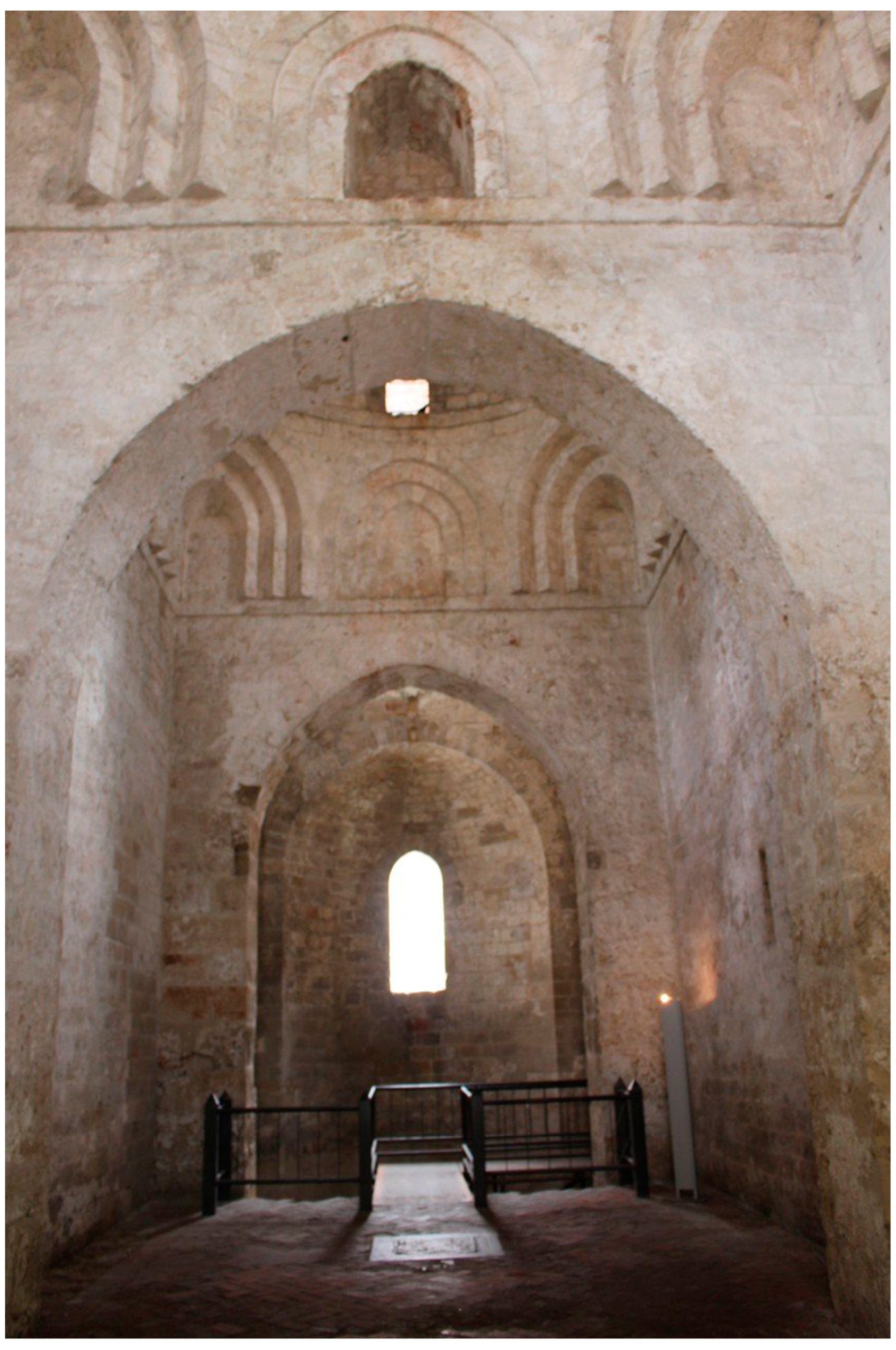
The plan of the church is shaped as a commissary cross with a single nave (
Figure 3). Two major cubic spans run lengthwise, while a crosswise transept protrudes at each end to two outward spaces, a
diaconicon (on the left) and a
prothesis (on the right).
Separated by the central chancel with similar dimensions, these rooms are cubic as well but smaller than the spans of the nave. The lateral wings of the transept have been provided with two small cylindrical recesses carved into the masonry thickness. The chancel ends in an apse which is curved outward. The five spans of the church are surmounted by hemispherical domes, in a spatial abstraction with a strong algebraic and symbolic meaning. On the side walls of the church, there are lancet arched windows which were originally covered by plaster grills. The 1880 restoration brought to light an ancient Islamic building, adjacent to the church, made of a rectangular hall covered by three false cross vaults added in the 17th century, the rest consisting of a porch and a courtyard, used for liturgical celebrations as far back as the Norman age. The Islamic building, called “Islamic Hall”, is accessible from the prothesis of the church and the external garden, and it is lit by a row of narrow and oblong windows along its perimeter. On the walls of this hall are visible traces of frescoes representing the Madonna enthroned between St. John’s blessing and St. Hermes.
As in the previous case, in this church internal and external walls are made of sandstone staggered and grouted ashlars with no embellishments, except for the external rings in the upper arches of the bell tower that overlooks the
diaconicon, in the internal windows above the string course frame, and in the squinches shaped as consecutive recesses that connect the square plan spans to the hemispherical domes. The latter are covered on the outside with red plaster, constituting one of the most iconic images of the Arab-Norman itinerary in Sicily and of the city of Palermo (
Figure 4) [
22]. The cross vaults in the presbytery are made of sandstone masonry with no covering as well, different from the false vaults of the suspended ceiling in the Islamic Hall, which are not load-bearing and made of reeds and plaster. Floors are uniformly paved by terracotta herringbone tiles.
3. Data Acquisition
Data acquisition on the two churches has been planned in different ways. A complete digital survey combining Terrestrial Laser Scanning (TLS), Unmanned Aerial Vehicle (UAV) and topographical methodologies was carried out in St. John’s of the Lepers; a TLS survey alone was carried out instead in St. John’s of the Hermits. In the latter case, the use of UAV systems was forbidden by the legal restrictions on drones which affects this part of the old town.
In both cases, on-site inspections were preliminary to the surveying to cover and match all of the areas of interest and to highlight any critical aspects of the work. The main constraints for the data acquisition were areas that were inaccessible for safety reasons and archaeological excavations, groups of tourists and believers visiting the monuments, and the presence of furnishing and vegetation, which could have created gaps on the acquired surfaces. A very critical aspect of acquisition in both churches was the connection between the internal and external environments, made only through the entrances, which required extra planning and attention during the survey.
TLS surveys were arranged to detect the whole accessible areas of the churches in their external and internal parts. All assessments have been made related to the laser scanner features, the architectural structures, and the conditions of the sites. Data acquisitions were accurately planned to optimize the number, the positions, the resolution and the field of view of the scans. Since it was not possible to use targets, an adequate level of overlap between scans for the subsequent registration phase was also planned.
The 3D documentation was performed by a FARO Focus 3D S120 phase shift laser scanner. This device is characterized by a ranging error of ±2 mm at 10 m and 25 m each at 90% and 10% reflectivity with the ranging error defined as the systematic measurement error, a range from 0.6 m up to 120 m in indoor or outdoor with ambient light and normal incidence to a 90% reflective surface, a measurement speed up to 976.000 points/second, and a vertical and horizontal field of view of 305° and 360°.
3.1. The Survey at St. John the Baptist of the Lepers
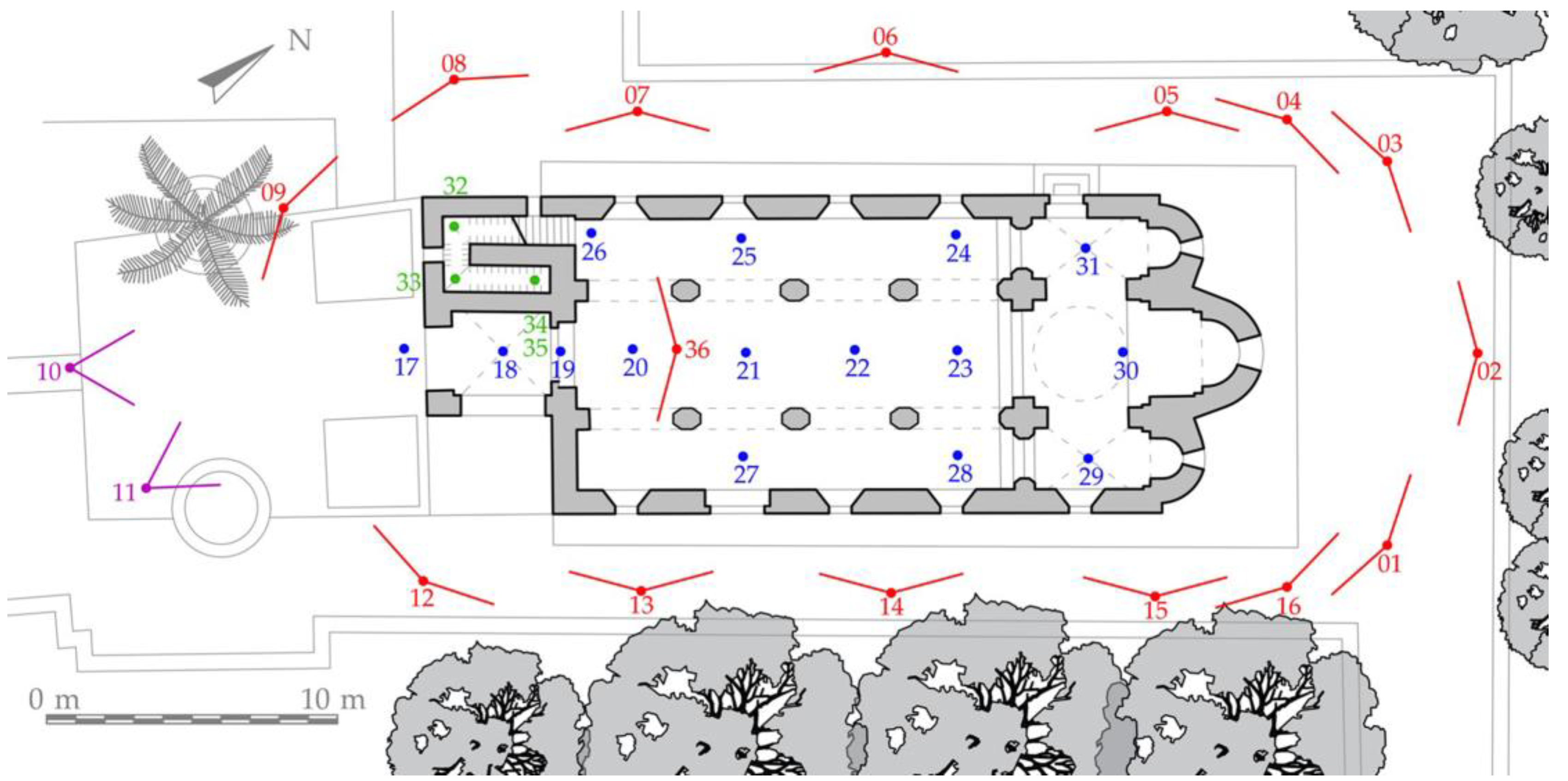
In St. John’s of the Lepers, the TLS survey was performed by setting the single scans according to the scan settings reported in
Table 1. Data acquisition provided 16 outdoor and 20 indoor scans, carried out as shown in
Figure 5. All external scans have been performed around the perimeter of the church, whilst the 20 internal scans were taken to have a complete coverage even in the most inaccessible and darkest parts; three scans were carried out on the porch, 10 on the naves, three on the transept, and four on the stairs to the bell tower and a storage area.
As in previous works where a UAV survey has been used for the 3D reconstruction of historical buildings, different image configurations were adopted [
23]: a classical nadiral flight to view the roof and the domes and frontal-view flights on the three façades of the church (the fourth one was covered with dense vegetation). Two circular flights with an oblique camera (30° and 45° from the horizon) for the roof and the façades have also been added. Indeed, the use of oblique photographs is a simple way to improve the results obtained by UAV photogrammetry [
24].
The image acquisition was achieved with a DJI Mavic Mini UAV drone flying in automatic mode via the Dronelink app for flight planning. Only the flights parallel to the façades required manual controlling of the drone.
The topographic survey was carried out by measuring a closed traverse on the outside of the building. This was measured with a Leica TPS 1105 total station and was made of five vertexes, roughly positioned on each side of the church. The coordinates of those vertexes were calculated in a local reference system obtaining a Root Mean Square Error (RMSE) of ±4 mm for the planimetric coordinates and ±1 mm for the height component. The topographic survey was used to measure the coordinates of 22 points, uniformly distributed on façades, which are used in the photogrammetric survey as Ground Control Points (GCPs).
3.2. The Survey at St. John the Evangelist of the Hermits
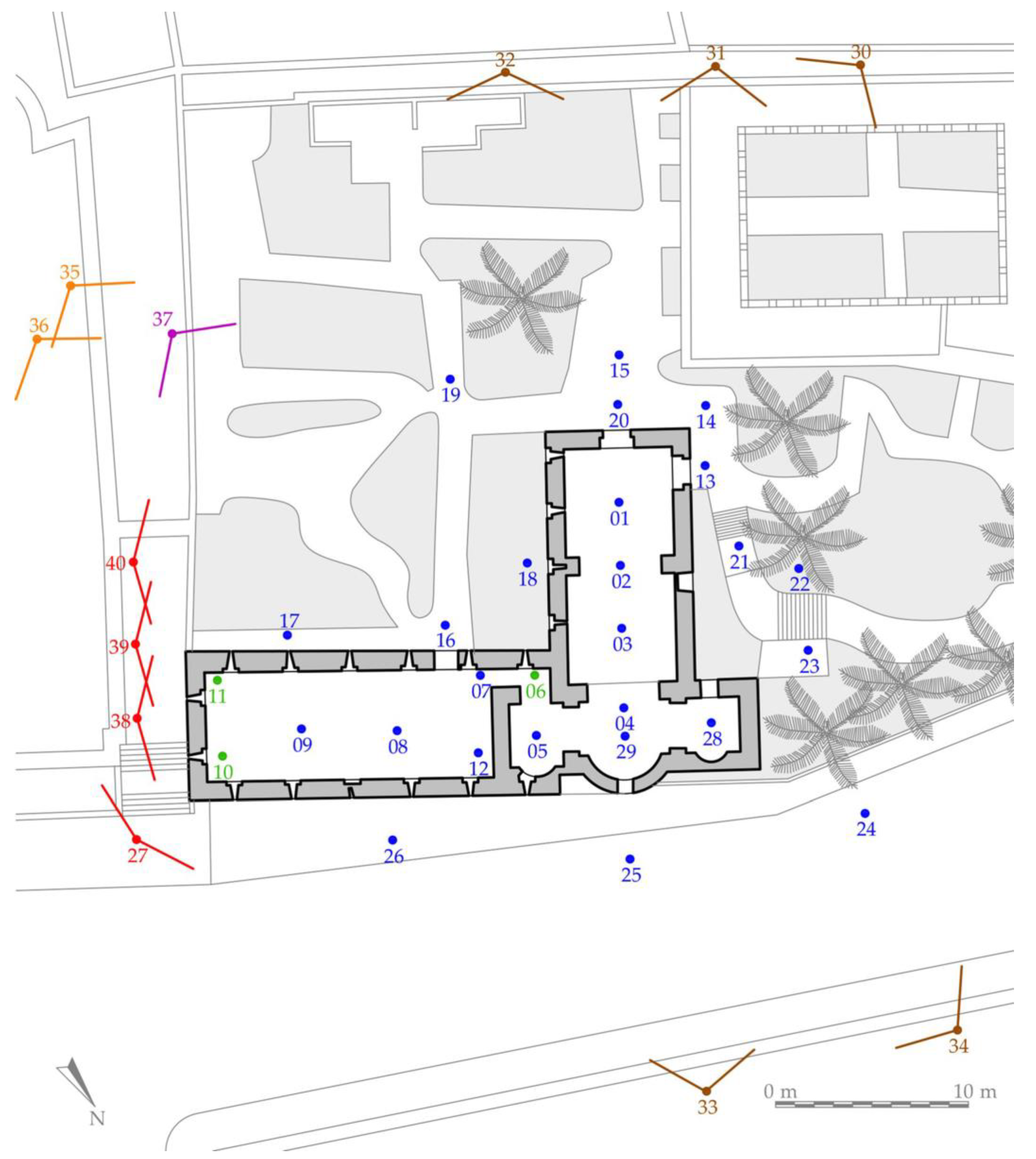
In St. John’s of the Hermits, data acquisition provided 26 outdoor and 14 indoor scans, positioned all around the building (
Figure 6), according to the settings reported in
Table 2.
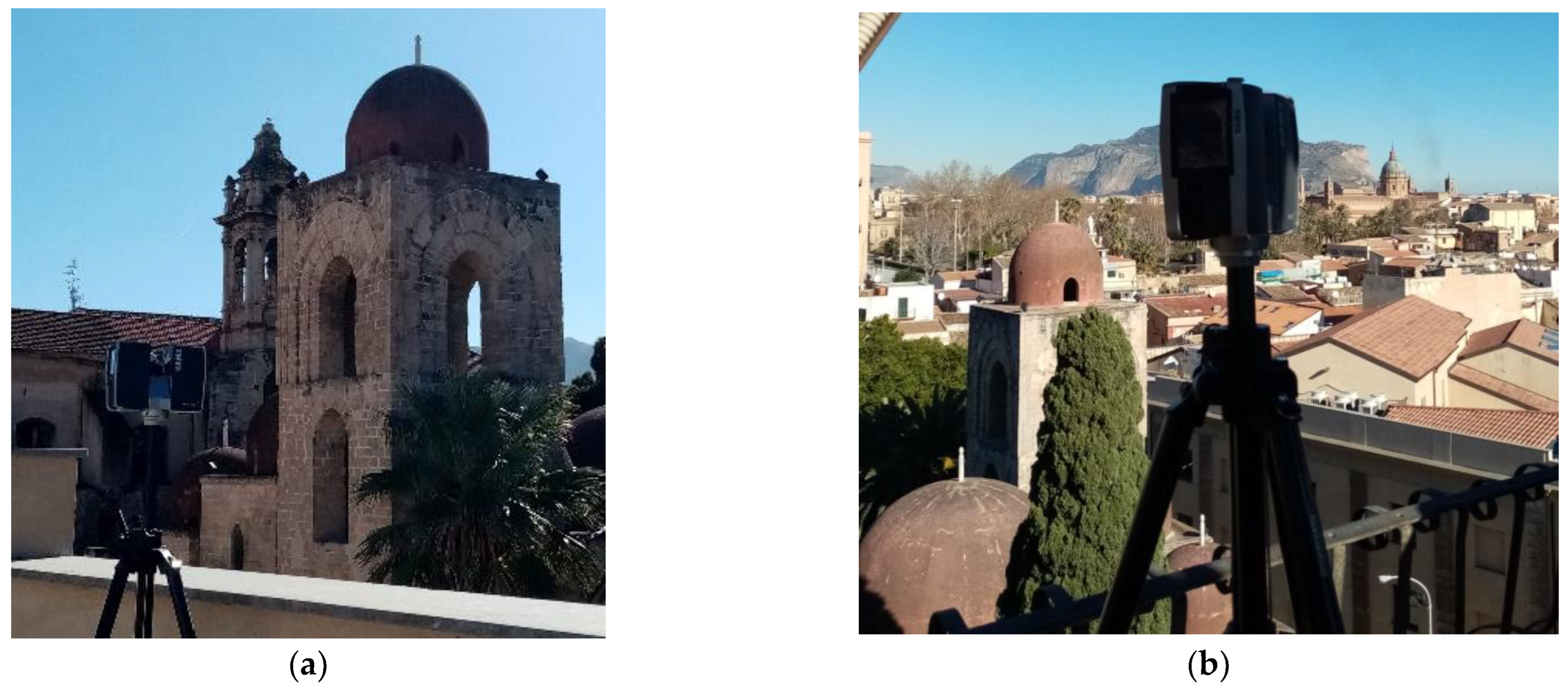
Indoor scans have been taken inside the church and the Islamic Hall. In particular, two of them have been performed in the archaeological trench along the apses. A total of 17 outdoor scans were located on the building premises around the garden and the street. Due to the flight restrictions and the impossibility of reaching high parts with UAV photogrammetry, nine external scan locations were placed in tall neighbouring buildings to capture the surface of the domes (
Figure 7).
4. D Data Processing
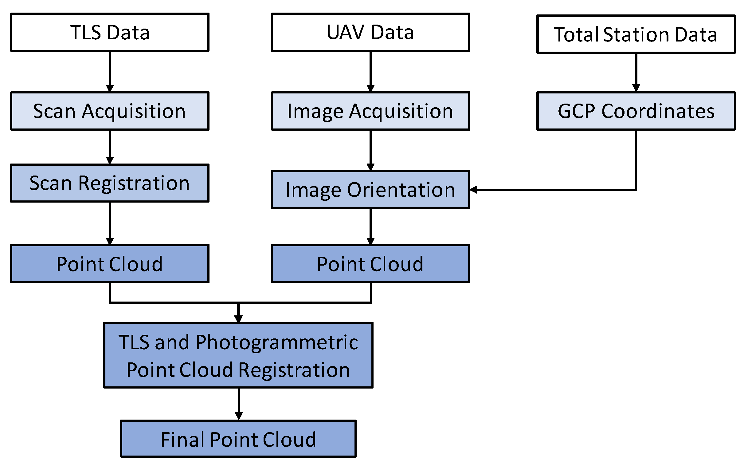
4.1. Data Processing for St. John the Baptist of the Lepers
The data acquired in St. John’s of the Lepers’ church were processed according to the flowchart in
Figure 8.
The 36 scans from the TLS survey have been imported into Autodesk ReCap, where an automatic optimization method, based on the Iterative Closest Point (ICP) algorithm, aligned and registered the scans without any possible interventions by the operator. The resulting point cloud was made by more than 553 million points (distanced from each other by 3 mm on average), which in a further step has been stripped from vegetation, close surroundings, etc. with manual segmentation, reducing the point cloud to 360 million points.
The photogrammetric processing was executed with Agisoft Metashape software following the typical pipeline based on image orientation, image optimization and dense point cloud generation. After image orientation with the typical Structure from Motion (SfM) approach, the optimisation process (a full bundle adjustment procedure simultaneously refining exterior and interior parameters) was carried out by setting a camera model with three radial distortion parameters and two tangential distortion parameters. A total of 22 GCPs were used for the orientation of the images. The mean re-projection error was about three pixels; the RMSE in object space for the GCPs was about ±1 cm. Finally, the dense point cloud was built by selecting the high-quality setting; this setting allows the use of images downsampled by a factor of four with respect to the original images, allowing for the obtaining of extremely dense point clouds. The point cloud was then filtered and cleaned of noise and irrelevant parts.
Next, the TLS and the UAV point clouds were aligned through a cloud-to-cloud registration procedure using CloudCompare software; once they overlapped and were superimposable without anomalies or discrepancies, the UAV point cloud had been stripped from redundant data. Only the roofing parts have been retained and merged with the TLS point cloud, forming one point cloud made of more than 283 million points (
Figure 9). Finally, this point cloud has been subsampled in a “spatial” mode forcing a minimum distance between two points to 6 mm, resulting in 100 million points.
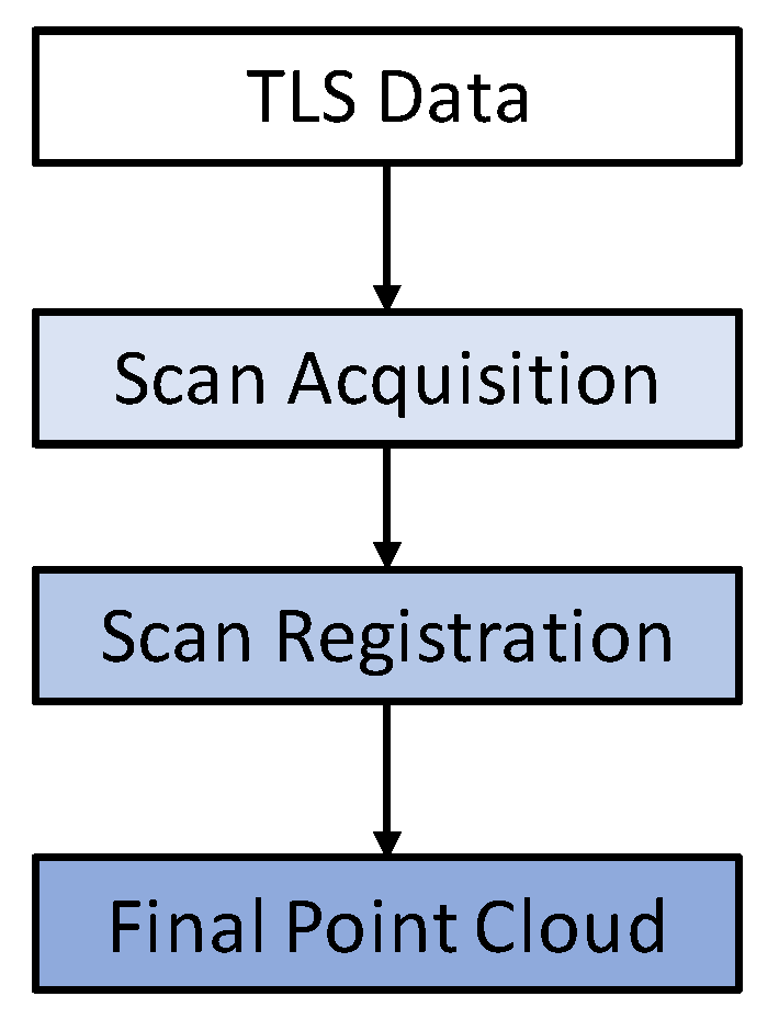
4.2. Data Processing for St. John the Evangelist of the Hermits
Since a UAV survey could not be performed on the St. John the Evangelist of the Hermits’ site, in this case the data were processed according to a workflow different from the one collected in St. John the Baptist of the Lepers’ church (
Figure 10).
The scans from the TLS survey were automatically aligned and registered in Autodesk ReCap. The resulting point cloud was made by more than 603 million points, with an average distance between points of 3 mm. They were first filtered from noise and irrelevant parts to 360 million points, and further sub-sampled in CloudCompare to reduce its excessive resolution and to minimize the computational effort. In this case, the “spatial” mode for subsampling has been used as well, setting the minimum distance between two points to 6 mm; the final overall point cloud was reduced to about 82 million points (
Figure 11).
5. HBIM Modelling
5.1. The Organisational Scheme for Knowledge-Based HBIM Exploitation
The final point clouds for both the churches proved to be a good result for the case studies, without artefacts or significant voids. Once imported into a BIM environment, they were able to provide all of the initial information (geometry, material and colour) for the further development of their respective digital models.
Once the data processing was completed, the huge amount of one million 3D points collected during the surveys described the geometrical surfaces of both buildings with high accuracy, but the interpretation of the structures would have been the next necessary step. The creation of an HBIM model based on point cloud information first requires the semantic decomposition and identification of architectural components and their mutual relationships and hierarchies [
25]. This is the reason why operators must understand and digitally follow the construction process used by the craftsmen when the monuments were built. A correct HBIM approach needs to adequately represent the historical architecture, define its peculiarity, and reproduce its logical structure as consistently as possible [
26].
If knowledge is a guiding principle, so-called “knowledge modelling” could be considered a strategy for understanding, preserving, and managing CH sites in the medium-long term [
27]. Aimed at the implementation of knowledge modelling for the digital reconstruction of the churches, the HBIM process followed in this research was arranged according to the organisational scheme in
Figure 12, and divided into three semantic domains (the artefact, the HBIM requirements and the actors involved), which were recursive, influenced each other, and always focused on the models. The modelling process has been divided into three different strategies reflecting levels of generalization. These strategies regulated the identification and the addition of semantic significance to the items:
global: this was applied to both churches as a reference for the data collected during the surveys and visual inspections. It refers mainly to the investigation process which preceded the modelling, with cognitive and interpretative research;
macro-areal: for spatial classes connected by mutual relationships (naves, spans, etc.);
elementary: for construction classes of single items in a unit (columns, walls, arches, etc.).
The decomposition of the model into its constituent elements encourages the analysis of each item’s role in its broader context. The classification of the case studies into spatial and construction elements, to be modelled as single objects, was aimed at following the BIM implementation. It was necessary to exploit the BIM tool’s behavioural rules of categories, families, and types to effectively represent the buildings’ hierarchical structural configuration [
28].
Without a formal ontology model, this organisational scheme has been manually implemented into the Revit relational database editing the
family >
family type >
instance properties to have an objects/relationships-oriented representation based on assembly, spatial, and construction rules [
29]. Spatial classes of the macro-areal strategy have been subdivided into typological aggregations with similar functions, such as naves, which in turn were subdivided into spans. Construction classes in the elementary strategy labelled all the components of a unit, such as the arches, pulvinus, columns and so on forming a side of the span, where each of them was subdivided for materials and other properties.
5.2. Modelling Phase
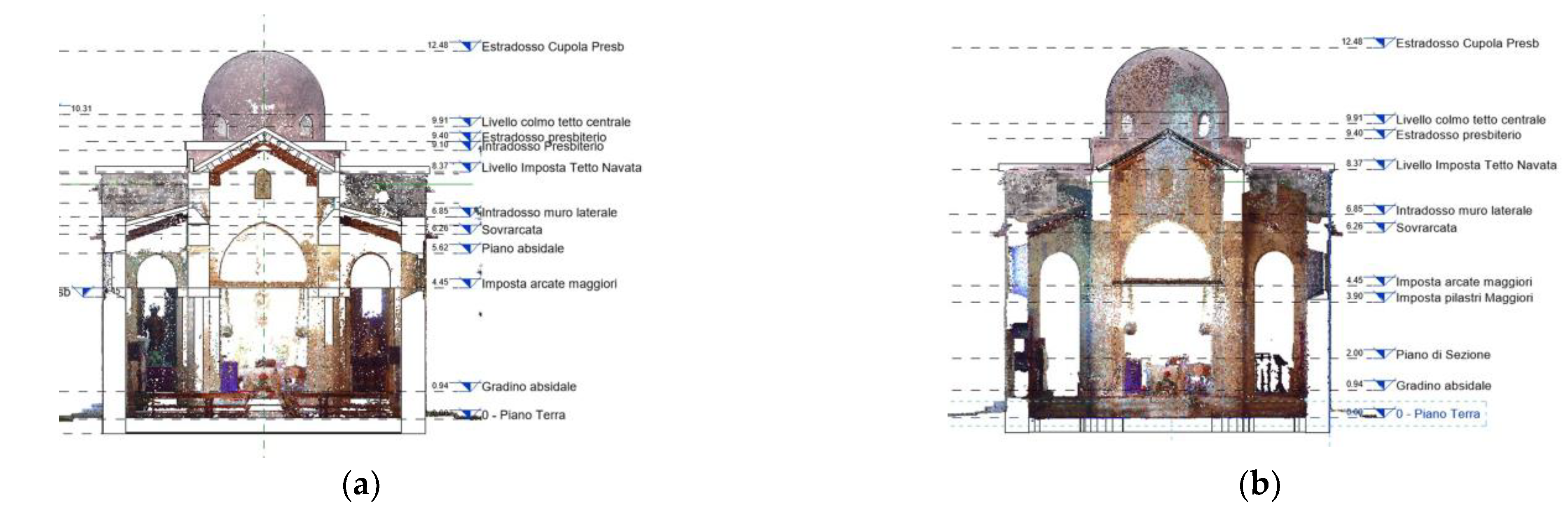
After the decision-making approach was defined as described in the previous paragraph, the HBIM modelling phase was aimed at turning (with manual processes) the geometric information contained in the point clouds into recognizable semantic items to be linked to the historical and construction data.
The BIM models of the case studies, capable of describing the whole architectural systems and the features of single elements in their dimensions and functions, were developed through the Revit software by Autodesk. Thanks to its “Insert Point Cloud” tool, the point cloud resulting from the surveys has been linked to this software and used as a “scaffold” [
28]. The modelling phase began by defining the main levels of the structures (such as the ground floor, presbytery floor, storeys on the bell towers, roof planes, etc.); indeed, the correct insertion of the parametric elements was guaranteed by the necessary views on the four fronts and significant section planes (in the centre lines of the spans or in correspondence of long and cross axes of the churches) of the point clouds as shown in
Figure 13.
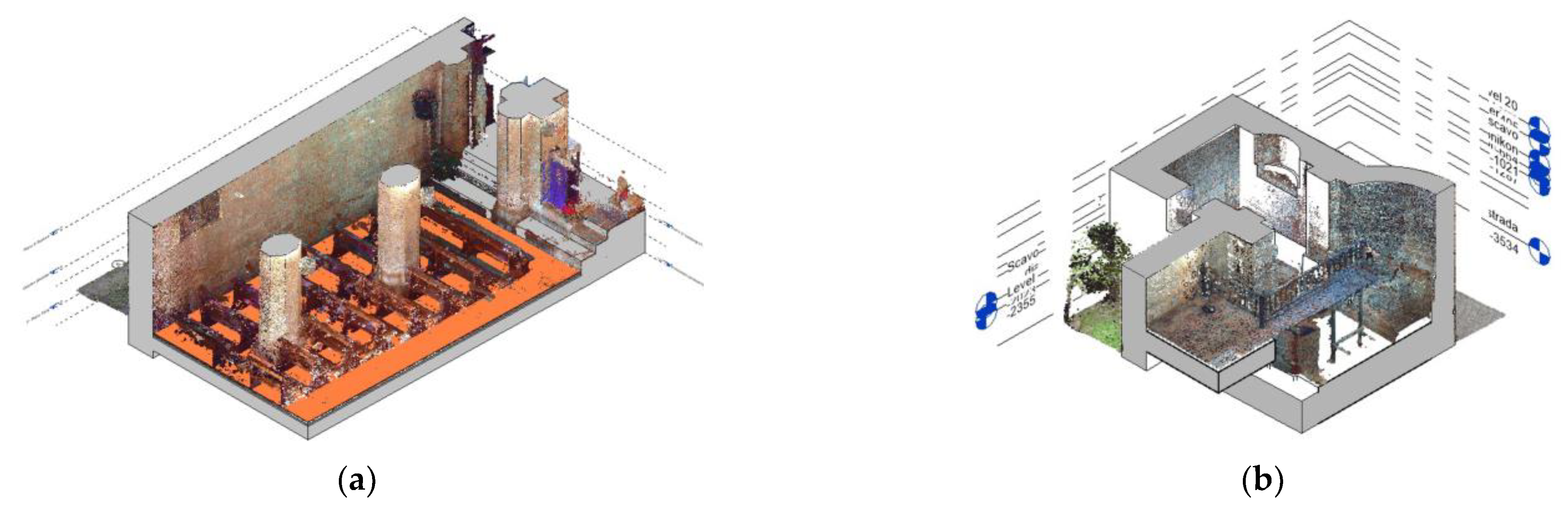
This preliminary setup allowed for the identification of the structures [
30]. All of the essential elements (i.e., straight and curved walls, pillars, floors, roofs, etc.), were shaped straight away following the actual outline of the point clouds in plans and sections, thanks to the in-built system “families” already available in the software. The latter are groups of elements controlled by the type and instance parameters within the project. An example of system families in the models are the apses of one church, which have been shaped through the “Curve wall” command, where the “Connect” option was activated to join them to adjacent walls. Models at the end of this phase were as shown in
Figure 14.
However, the majority of the architectural features regarding a CH building are excluded by the customary BIM implementation tools, and very often alternative non-standard solutions must be found, trying to balance the right level of simplification, the time of elaboration, and the deviations from the real object which finally affect the representation of the model.
In these two models, many secondary features were modelled by loadable families, which required additional time. These types of families are not a default setting in the Revit project and they had to be created and implemented on an ad hoc basis. Indeed, BIM authoring tools have been conceived and designed for new construction, and they inevitably rely more on system families, albeit the most updated versions of the software now include many editable templates for creating brand new families. Thanks to the family editor, loadable families can satisfy any customization requirement when it comes to many architectural elements typical of CH which are slightly irregular or deformed or far from an ideal geometry due to past construction methods, structural failures or similar reasons. They constitute reliable implementations whenever CH buildings require a more flexible input system for geometry representation [
29].
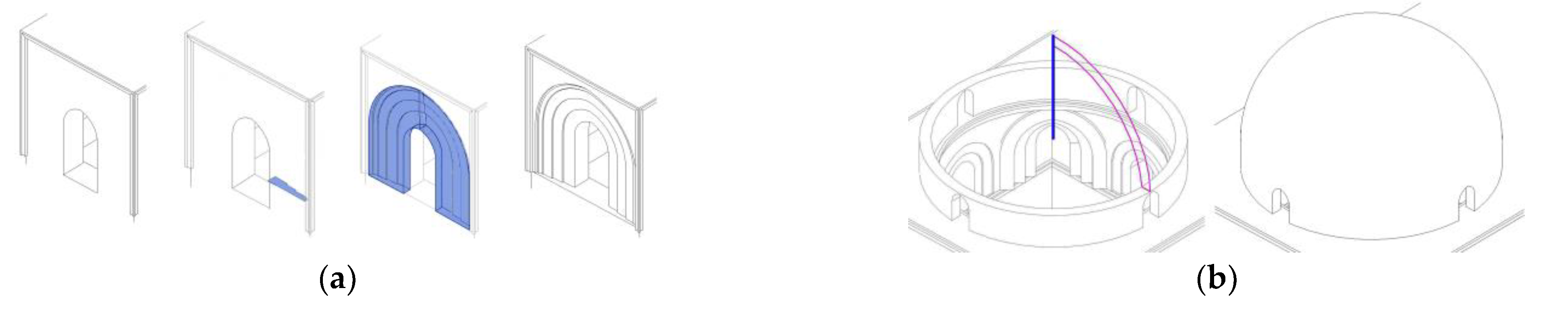
The commands available on the “Forms” panel (usually solid and void extrusion, and revolve and sweep) from the “Create” ribbon, were very helpful in creating new loadable families for the case studies. For example, pillars have been extruded from their irregular octagonal or cruciform perimeter. A similar method was followed for shaping the lancet arched windows as a void extrusion, where their typical rings have been swept from a drawn profile and subtracted from the wall. Domes have revolved around the generator profile with variable thickness. In this case, a geometric approach was preferred to ensure that the external and internal surfaces of the domes were not perfectly offset. The process through which these details have been modelled is shown in the following pictures (
Figure 15).
Cross vaults have been shaped through the “roof on face” tool (
Figure 16). The irregular surface of each vault has been created and kept on CAD and then imported on the BIM platform where the structures have been modelled with a standard thickness (only the lower soffit was known from the point cloud) and stratigraphy (exposed bricks or a cover layer of plaster).
The HBIM models of St. John of the Lepers’ church and St. John of the Hermits’ church were created by trying to reflect the actual shape of the buildings with the highest fidelity, reproducing even the typical discrepancies due to the construction methods of the past (
Figure 17). For instance, the not perfectly orthogonal position of the main walls was pursued by disabling the “snap” option when tracing their alignment, or the windows were slightly different in dimension and not perfectly aligned on the same level, which was respected and accounted for when modelling them one by one.
5.3. Semantic Signification and Data Enrichment
The advantage according to which BIM has received special attention from the CH field and its methodology has been adopted for modelling historical sites is that, in a BIM environment, buildings are not just modelled on their geometrical components alone, but they are decomposed and rearranged in a smart organisation of entities and relationships. Any digital model aims to provide semantic meaning and data enrichment to the architectural features of the represented CH buildings. This process includes, in a single modelling environment, all the knowledge acquired through the planning and the data collection phases, and it is affected by the different specialists’ interpretation. This knowledge about contextual cultural elements must be included in the digital model as an immaterial value of the CH assets to share comprehension and awareness finalised to their management purposes.
Semantic signification in the case studies models has been enriched by editing the settings in the families of the digital items once they have been modelled. This has been done by adding the appropriate keys which would have affected all of their non-geometric attributes; in this way, consistent information for each architectural feature has been assigned to the conceptual system of metadata linked to the physical structures.
Alongside Revit’s default attributes which refer to materials, dimensions, layers, constraints, and phasing, a set of specific attributes has been implemented with regard to the state of conservation, the original configuration, any potential alterations or decays, etc., which applied to all those items of the churches to be considered as variants.
Figure 18 shows the case of the cruciform pillars in the presbytery of St. John’s of the Lepers church. They were pretty much similar (just two in the building) with no trace of decay, so global parameters affecting that loadable family were altered, as they would have affected the two items at the same time with no need of implementation of specific values for each of them.
All types and the instances identified within the organisational scheme have been represented according to aggregation, topological, and directional relationships among entities, which could have been horizontally or hierarchically structured [
31], as shown in
Figure 19. For example, aggregation is a classical hierarchical tree composition among parts of the same unit (i.e., all the items in a span).
The semantic enrichment followed in the two study cases did not seek to achieve an omni-comprehensive representation of the object, but it was structured for giving each actor the information useful for a decision-making process only and the context necessary for adequate interpretation and understanding [
32].
5.4. Data Validation and Accuracy Assessment
At the end of the semantic enrichment stage, a geometric assessment for both obtained models was carried out to validate the whole process and benchmark their reliability against one of the HBIM requirements: the greatest possible closeness to the real artefacts, with a minimum deviation. In this operation, the expected results are usually affected by the quality of the initial data collected during the survey and by the modelling tools which has been chosen for the models. In both case studies the architectural features were very basic, and modelling has been performed through the adoption of ad-hoc families which guaranteed the desired accuracy. Indeed, for particularly complex and irregular shapes, for which the “Form” operations described in the last paragraph are not sufficient, it might be appropriate to integrate the model with NURBS (Non Uniform Rational B-Splines) which, taking advantage of the interoperability between different formats, are imported in the BIM environment and enriched by information [
33,
34].
The geometric assessment has been evaluated with a method based on minimum Euclidian distance by measuring the deviation of models from their reference data. One problem related to this method is the presence of furniture or other redundant items in the point clouds which have been excluded in the modelling phase, as they risk increasing the expected deviation [
35]. Therefore, point clouds have been stripped of all irrelevant features prior to the beginning of this analysis. This was performed through CloudCompare software, where each point cloud and its respective model (exported from Revit as meshes in .stl format) sharing the same coordinate system have been superimposed.
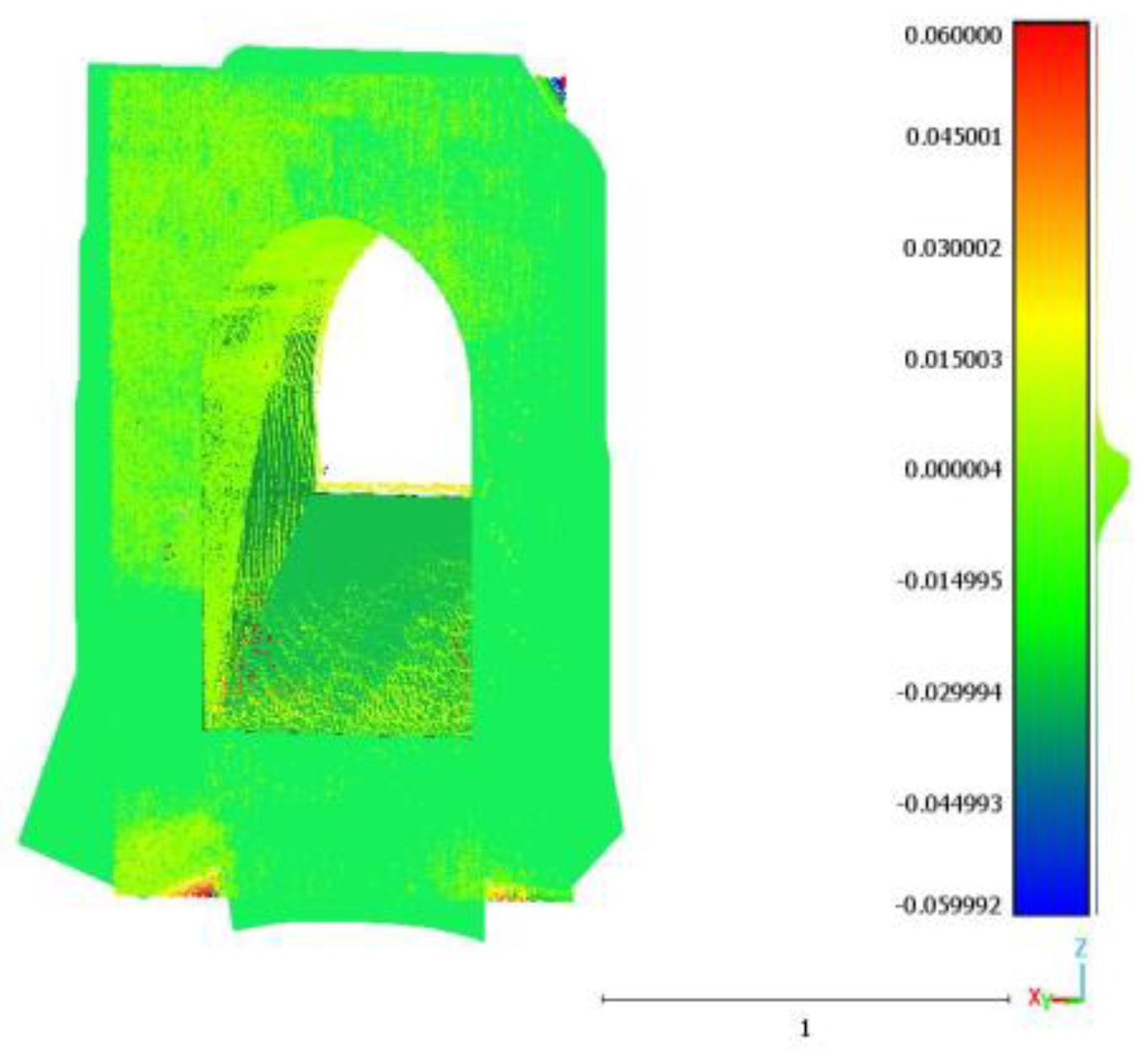
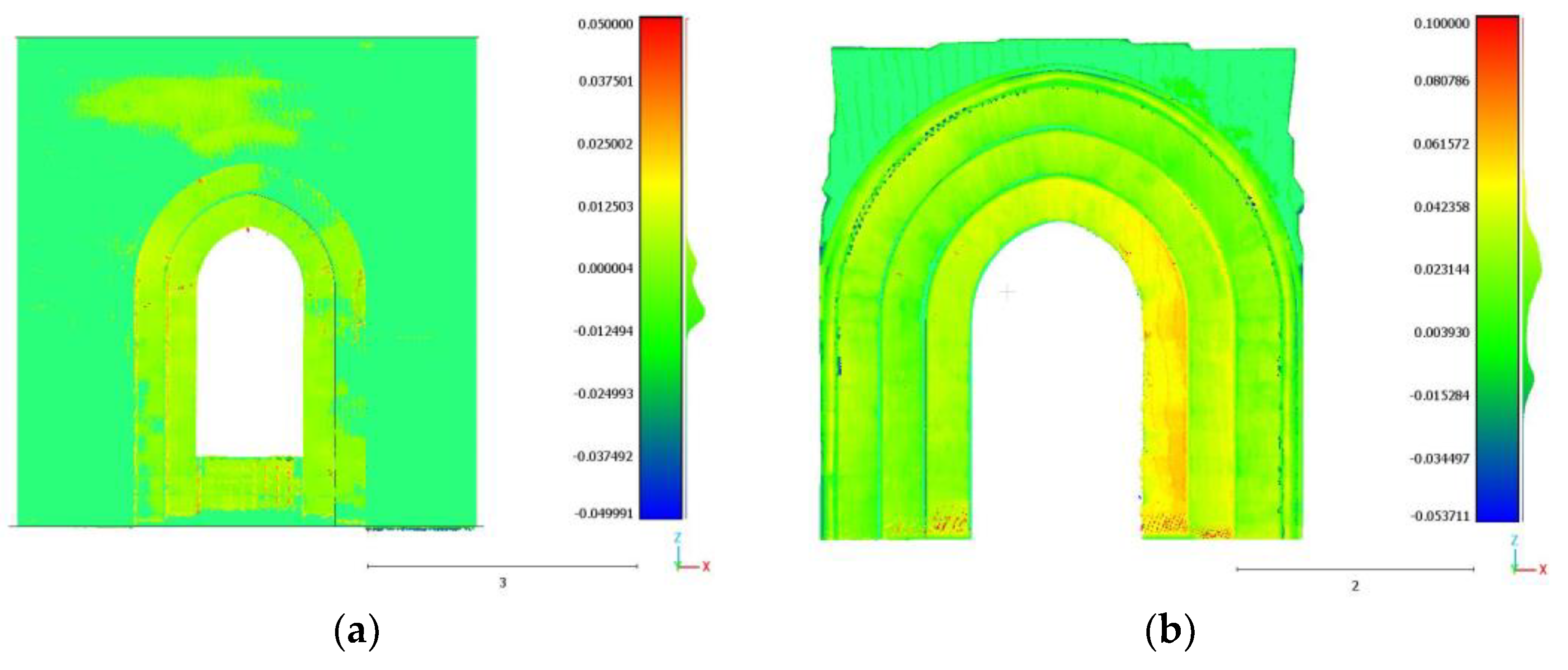
An initial general assessment indicated that neither church showed any structural failure compared to their ideal shape; only some small irregularities such as non-planarity, out-of-plumb and asymmetries have been highlighted. These minor differences are mostly due to the construction methods of the past. For a more in-depth analysis, some architectural elements of the whole building (columns and arches, domes and typical Arab-Norman windows) where the major discrepancies were expected, were analysed in detail. The assessment showed the value of the deviation between modelled surfaces and references, classified by colour-coded scales in gradients according to their distances. Distance maps are shown in
Figure 20,
Figure 21,
Figure 22 and
Figure 23; statistical values (mean distances and standard deviations) are reported in
Table 3. These results are indicative of how it is possible to obtain HBIM models of ancient architectural elements via a manual process with good accuracy without resorting to a NURBS surface.
6. Discussion
The present work proposed a Scan-to-BIM approach applied to HBIM, where the geometric description of the models has been integrated with knowledge-based semantic enrichment about all of the available non-geometric data in order to match the requirements of CH management. At the end of this research, the results allow us to make assessments regarding the data acquisition, the data modelling, and the methods the models have been developed with.
The survey methodologies (TSL, UAV and topographic) carried out in the case studies gathered hundreds of millions of the highest-quality 3D points in a few work days per survey. Whether the data processing has been simplified by automatic or semi-automatic methods, this was not possible for the modelling phase, which was performed by manual procedures only. Whilst in-built system families available in the Revit software helped to shape standard items straight away, the singularity of many other architectural features needed more flexible solutions. New loadable families have been created using the generic metric family template, where bespoke architectural features have been modelled through the appropriate commands, and then stored and loaded in the models; this necessary step required additional time, but it offered the indisputable possibility of representing the peculiarities of these buildings in their actual shape and dimensions as traced from the point clouds, without falling into the forced idealisation of the models.
As the maximum geometric and semantic correspondence between the architectural features and their representation was pursued, the created loadable families were not parametric. A new parametric library concerning the Arab-Norman architectural style is to be implemented for further development of the models that will be suitable for use in similar buildings. This ad hoc library was aimed at sharing awareness and documentation about the peculiarities in this example of Sicilian architecture, since BIM environments usually do not include libraries dedicated to the styles from the past, except for the classical and Renaissance ones. Indeed, integrating the most common elements of the Arab-Norman heritage styles to other inclusive libraries already available would help both the automation of the modelling process for similar buildings and the expansion of BIM technologies for CH preservation purposes. This result would have been impossible to pursue without the adoption of a knowledge-based strategy, which started from the investigation process and was implemented at the end of the modelling phase. It was chosen to maximize the HBIM potential by keeping all of the meaningful non-geometrical components of the architectural heritage, with a scheme based on adding non-geometrical attributes with manual procedures. Each element in the model was created by first considering its own identity (real geometry, position, constraints and materials) and then its role in the related structure.
The post-modelling semantic enrichment phase was a resource-consuming interpretative labour as well, but it led to a hierarchical organization of the models (and of their related data) which can help in the management of public CH buildings. These indisputable results have to be considered as homogeneous in their immediate effects even if they belong to different approaches made at the beginning and considering separate aspects of the HBIM (the geometric and non-geometric data and their effective representation and interpretation). This began with the awareness that the more that is known about the real object, the more coherent the final model will be. The biggest effort in HBIM is understanding how the building behaves, and the greatest achievement is producing a 3D model which digitally replicates that behaviour. Obtaining this result can be helpful to different kinds of users and technicians from different disciplines.
7. Conclusions
This research was aimed at establishing and implementing a suitable workflow and an appropriate assessment of a Scan-to-BIM approach in the field of CH considering advantages, limitations, and problems. Two Scan-to-BIM processes were tested on the churches of St. John the Baptist of the Lepers and St. John the Evangelist of the Hermits, two magnificent built examples of the Arab-Norman heritage in Palermo.
The work has been structured to endorse the assumption that in-depth knowledge of the two buildings (plus other similar and coeval ones belonging to the same period) should have been compulsory in order to develop effective models. All of the collected data, coming from the investigation process and the surveys, served as a reliable basis for replicating geometrical and non-geometrical information and needed to be interpreted prior to being merged into parametric models.
The advantage of using BIM environments for modelling the case studies is that HBIM is neither to be used as a mere geometrical representation of the real site, nor is it to be considered completed and static at the end of the process, but revisable at all times. Indeed, once the key values were enriched with semantics, the knowledge-based models were implemented to include all of the aspects required for documentation, simulations and further analyses. Thus, they are integrated archives capable of storing the collected data and with room for improvements, updates and inspections according to the characteristics of the case studies. The HBIM can be explored and exploited on a flexible, collaborative platform to match the CH preservation requirements, thus providing an effective contribution to the maintenance of the historical heritage.


