Article

Urban Morphometrics and the Intangible Uniqueness of Tangible Heritage. An Evidence-Based Generative Design Experiment in Historical Kochi (IN)

1
Urban Design Studies Unit, Department of Architecture, University of Strathclyde, Glasgow G1 1XQ, UK
2
UNICITI, 31400 Toulouse, France
3
Welsh School of Architecture, Cardiff University, Cardiff CF10 3NB, UK
*
Author to whom correspondence should be addressed.
Heritage 2021, 4(4), 4399-4420; https://doi.org/10.3390/heritage4040243
Submission received: 31 August 2021 / Revised: 26 October 2021 / Accepted: 15 November 2021 / Published: 18 November 2021
(This article belongs to the Special Issue Heritage Patterns—Representative Models)

Abstract

:
Asia is urbanising rapidly. Current urbanisation practices often compromise sustainability, prosperity, and local quality of life while context-sensitive alternatives show very limited impact. A third way is necessary to integrate mass-production, heritage, and human values. As part of UNICITI’s initiative, A Third Way of Building Asian Cities, we propose a scalable and replicable methodology which captures unique morphological traits of urban types (i.e., areas with homogenous urban form) to inform innovative large-scale and context-sensitive practices. We extract urban types from a large set of quantitative descriptors and provide a systematic way to generate figure-grounds aligned with such urban types. The application of the proposed methodology to Kochi (IN) reveals 24 distinct urban types with unique morphological features. Profiles, containing design-relevant values of morphometrics, are then produced for a selection of urban types located in the historical district of Fort Kochi/Mattancherry. Based on these, figure-ground design demonstrations are carried out in three sample sites. Outcomes seem aligned with the urban character of their respective types, while allowing distinct design expressions, suggesting that the proposed approach has potential to inform the design in historical/heritage areas and, more broadly, the search for a Third Way of Building Asian Cities.

1. Introduction

Recent economic growth in Asian countries has resulted in rapid urbanisation in the region. Many cities are both rapidly expanding in size and population. These cities hosted 0.3 billion urban dwellers in the late 1950s, 2.1 billion in 2015, and are projected to host 3.3 billion by 2050 [1]. This unprecedented growth comes at the cost of significant vulnerabilities. The United Nations (UN), for example, estimates that 31.2% of the urban population of Central and Southern Asia currently reside in slums [2]. In addition, Asia is the most climate vulnerable region in the world. Summer temperatures are estimated to rise 6 degrees that could result in a rise of the sea-level by 1 m to affect most Asian cities, increasing the risk of floods and storm surges along the coastlines. Urban development also adds to these vulnerabilities due to the high greenhouse gas emissions associated with the use of conventional concrete, cement, brick, and steel materials [3]. The Global Infrastructure Basel Foundation estimates that more than 75% of the infrastructures that will be existent in 2050 are yet to be built, and a large part of them will be built in Asia [4]. Aforementioned challenges are likely to exacerbate further if the business as usual (BAU) way of building cities continues, in which case Asian urbanites will be locked into a low quality and unsustainable life conditions for decades.
The housing industry in Asia currently offers two main ways of urban expansion. The first features mass-produced building materials and neighbourhood designs out of corporate-centred urbanisation processes (Figure 1, left), targeting the expanding market of the urban middle/upper-middle class. As a result, Asian cities are overwhelmed by identical, standardised urban and building patterns repetitively iterated to cover most formally urbanised land independently from local social, economic, cultural, and environmental contexts [5].
This BAU way of building is associated with higher carbon footprints and shorter lifespan of buildings. Every year, the world emits over 30 GT of CO2 and nearly 40% of it are related to buildings, of which nearly 1/3 comes from manufacturing of conventional building materials such as iron and steel, cement, aluminium, and glass (estimate based on data from [8]). The operational energy consumed to run these buildings is also very high due to the incompatibility of the materials with the local context. Lighting, heating, ventilation, and air conditioning in glazed commercial buildings represent over 70% of the total consumed operational energy [9]. BAU buildings also last for less time. The average lifespan of a traditionally built building (bricks and wood) is at least twice that of a typical modernist building (reinforced concrete and glass curtain wall): 120 years versus 60 years [10]. The loss of place identity and sustainability associated with the BAU way of building cities goes hand in hand with the loss of economic competitiveness as qualified/talented individuals tend to settle in places with character and more liveable urban environments [11]. Related to this, the BAU way of building cities is also detrimental to urban liveability. According to The Economist Intelligence Unit, which measured liveability in terms of quality of life, mental and physical health, safety, walkability, public transport, and cultural and natural environments, and produced a ranking of the world’s most liveable cities, two Asian cities (Osaka and Tokyo) feature in the top ten, however they are both located in the only developed country of the continent (Japan) [12].
The second current way of urban expansion relies on sophisticated, sustainable, locally sensitive, and context-tailored designs (Figure 1, right) for the cultural and social elites. This, however, represents a very small portion of the overall built-up stock. Finding a third way to build both fast, well, and affordable, is crucial and non-deferrable if a viable alternative to the lose-lose choice between unsustainable/insensitive/malfunctional urbanism and slum ghettoisation is to be factually found. Such Third Way of Building Asian Cities should meet today’s infrastructure and housing needs of building fast and affordable in dense urban environments and, at the same time, the need to building unique, sustainable, and liveable cities made of places that recognise and treasure the spiritual and cultural identity of local communities as embedded in the spatial structure of tangible urban heritage. Most importantly, it should re-activate the interrupted cycle of continuous renovation and formation of the urban heritage of tomorrow, by consciously integrating in new planning policies and practices of the collective wisdom that historically was a natural part of the granular, local processes of city production. This is the mission of a non-for-profit initiative, A Third Way of Building Asian Cities, launched in September 2019 at the 55th ISOCARP World Planning Congress in Jakarta (ID), by UNICITI, a French think-tank and consultancy (https://www.uniciti.org, accessed on 31 August 2021).
This paper presents a contribution to phase 1 of the aforementioned initiative, which was initiated in December 2020. It aims at identifying viable alternative solutions that can help build a unique, sustainable, and liveable urban fabric in Asian cities today. In line with this initiative, we propose a replicable methodology, named Urban MorphoMetrics (UMM), that captures the morphological uniqueness of homogeneous urban areas and helps to design new masterplans with the advantage of a controllable awareness of it. More specifically, UMM: (i) identifies homogeneous patterns of urban form in cities, i.e., urban types (UTs hereon) via a rich description of current urban form, based on hundreds of numerical spatial descriptors (morphometrics); (ii) extracts from each UT its own numerical form code by distilling a sub-set of six main morphological features, which are relevant to city planning and place design; (iii) operationalises these profiles to inform the formation of evidence-based design codes (DCs hereon) in designated areas. UMM, is specifically designed to pair up richness of information with XL-scale of application, potentially fit to cover the whole of Asian cities. It is also of great relevance for urban heritage planning as it permits to capture the morphological essence of places and generates figure-grounds respectful of this essence, while not being replicas. More broadly, UMM allows to capture the “collective wisdom” embodied in historical/heritage urban types and shapes an urban future in line with it. This not only implies understanding and measuring the built heritage of the past, but also building tomorrow’s heritage, that is, urban areas to which future residents will attribute values of identity, attachment, and use, which largely stay unchanged through time.
While UMM must be applied to the whole of Kochi to function, including UTs that are not in historical/heritage context, a proof of concept of UMM is presented in this work through its application to the historical district of Fort Kochi/Mattancherry. Here, we demonstrate that despite working in very challenging environmental conditions and with a largely sub-optimal base of input data, the UMM seems to demonstrate a significant ability to capture relevant features of the city of Kochi, which is the base for the development of an innovative generation of evidence-based design codes (EBDCs). We obtained 24 different UTs, characterised by distinctive morphological traits. Morphometric profiles are then extracted for three specific UTs, located in the historical district of Fort Kochi/Mattancherry. Moreover, figure-ground-only design demonstrations are generated for a selection of blocks within each selected UT. Design demonstrations—not to be confused with proper masterplan proposals—are abstract design exercises enacted as part of UMM’s development. In this context, they are aimed at exploring the ability of UMM-based numerical design guidelines to lead a plurality of professionals towards design outputs which would be distinguishable from each other and yet visibly reflect the intangible “uniqueness” or “distinct character” of any UT, including historical ones. These exercises are to be considered successful if this intangible balance of unicity and typicality is achieved, insofar: (i) a radically reduced set of six only descriptors are plugged into the demonstration; (ii) figure-ground of building envelopes (rather than real building footprints) are actually designed, and (iii) demonstrations consistently achieve both terms of the balance across different UTs and, within each UT, across proposals by different designers.
The remainder of this paper is structured as follows: in Section 2, we illustrate the UMM methodology through which we identify UTs, obtain morphometric profiles, and operationalise them to generate figure-ground design demonstrations. We then present, in Section 3, the study area (the city of Kochi), its main geographical characteristics and urban development. In Section 4, we describe in detail the input dataset and urban form descriptors generated from it. We then show, in Section 5, the resulting numerical taxonomy of Kochi, the detailed morphometric profiles, and the figure-ground design demonstrations for three of its UTs. The paper finishes with a discussion of the results and conclusions in Section 6 and Section 7.

2. Methodology

The methodology is illustrated in two parts. First, starting from a large set of morphometric descriptors, we identify the UTs at city-wide scale and produce their morphometric profiles (statistical elaborations of all descriptors applied to each UT). The second part uses these profiles to inform the figure-ground design demonstrations. Whilst these tests are purely conceptual at the moment, we explore their potential for applicability in real-life scenarios.

2.1. Morphometric Taxonomy and Profiling of Urban Types

The technique for the classification of UTs used in this paper is a development of previous work by Fleischmann et al. [13], specifically designed for this application. We thus summarise next its main features and illustrate with more detail advancements proposed and applied in this specific work. The morphometric taxonomy is the quantitative classification of morphological patterns starting from single measurable descriptors of urban form. Each descriptor measures a single dimension of the physical city (e.g., building footprint, coverage ratio, block size), while their combination detects recurring morphological patterns in a specific study area. Descriptors measure a variety of dimensional and relational aspects of basic components of urban form, at the very local scale of the components themselves and for local areas, accounting for spillover effects typical of spatial phenomena [14]. While previous studies (see, for example, [15,16]) selected one or very few descriptors to test specific but narrow research questions, this approach is based on the idea of comprehensiveness as well as richness of information, retaining the largest number of morphometric descriptors utilised in urban morphology that could operationally fit our technical framework, augmented with a few new ones allowed by our method alone, to comprehensively describe the urban form under examination [17].
The morphometric taxonomy relies solely on two georeferenced vector datasets: building footprints and street network. From these, morphological cells (a quantitative version of the cadastral parcel or plot) are created via a Voronoi tessellation-based partitioning of space [18], reflecting the zone of influence around each building; 74 primary characters are then computed for each cell across the entire study area, allowing to numerically quantify morphometric elements (street segments, building footprints, and cells) in any urban fabric, by capturing the relationships between them and their immediate surroundings. The entire list of primary characters can be found in Fleischmann et al. [13]. As mentioned above, a crucial aspect of this approach is accounting for the local context: four different statistics, or “contextual characters”, are thus computed for each primary character over aggregations of cells around each cell and attributed to it. The interquartile mean is the average computed on the values between the first and third quartile of the distribution. The interquartile range is the range in values of the central 50% of the distribution. The inter-decile Theil index, a measure of local inequality, and the Simpson index, a measure of heterogeneity of values, are both measures of diversity. Full formulas for computing these statistics can be found in Fleischmann et al. [13].
Having computed the contextual characters, a cluster analysis is performed to synthesise this rich description and generate a taxonomy of UTs for the area under examination. The morphometric taxonomy presented by Fleischmann et al. [13] is based on the use of the Gaussian Mixture Model (GMM), a probabilistic version of the k-means clustering. However, the purely statistical nature of this technique, to a certain extent, jeopardises the result as, by not considering the spatial structure of the data, it introduces noise (i.e., misclassified buildings) in otherwise homogeneous UTs. For this reason, a different technique, i.e., agglomerative hierarchical clustering (AHC) [19], which imposes a spatial structure on the definition of the UTs is used in this paper. More specifically, AHC is a hierarchical technique of cluster analysis, which builds a tree (dendrogram) of clusters (UTs) starting from the single observations (buildings) up to a main branch, following a merge strategy based on the reduction of the sum of squared differences within all clusters. A third order connectivity matrix is used as a connectivity constraint to impose a spatial structure on the clustering (only nearby clusters can be merged together). The optimal number of clusters (UTs) is identified via the computation of the silhouette score, a common heuristic technique used for validating consistency in cluster analysis [20]. Since it is possible that the output of this method identifies UTs with too large variations in terms of urban form, successive rounds of clustering and silhouette scores can be performed on a selection of UTs to better differentiate sub-patterns. A final dendrogram, crucial to evaluate levels of similarity across UTs, can be built by recomputing the hierarchical tree starting from the cluster centroids of each UT.
Once the optimal solution is reached, morphometric profiles of UTs are built from six primary characters: cell area (CA), coverage ratio (CR), building footprint (BF), building elongation (BE), alignment to surrounding buildings (ASB), and mean distance between buildings (MDBB). These are selected due to the easy readability of their units (e.g., m2, percentages) and because they provide enough spatial information to generate coherent figure-grounds in sample sites, within specific UTs. Furthermore, they are often used in design codes and guidance, such as the National Model Design Code recently proposed by the UK Government [21]. Importantly, morphometric profiles are offered for each UT in one table, reporting for each of the six primary characters: (i) 15 intervals of values identified through natural breaks’ discretisation at the level of the entire study area, and (ii) the percentage of buildings falling in each of these intervals. This form allows designers to smoothly translate analysis outputs in (ranges of) design instructions.

2.2. From Morphometric Profile to Figure-Grounds

The development of figure-ground design demonstrations involved four professional urban designers of the UNICITI think-tank. They helped to conceptualise, test, and validate the workflow through a series of experiments. None of them had previously taken part in the development of UMM: they effectively acted in the role of end-users. This was intentional, as our aim was to test the applicability and effectiveness of UMM to professionals without any background knowledge. In particular, at this stage, we wanted to assess to what degree four different designers, working under an extremely reduced framework of six characters only, could come up with figure-ground proposals which: (i) were all different from each other, and yet (ii) all retained the typical “character” or “feeling” of the UT of reference.
A full illustration of the results of the exercise is provided in the Results section. The workflow developed by the UNICITI designers entails the following steps:
  • Selection of the sample site. This is usually a brownfield, or an area designated by local authorities as developable, within specified design constraints to be integrated in this workflow. The iterative testing carried out by the UNICITI designers showed that the method works well at the meso-scale, that is, an area comprising a few blocks (at least 100 buildings), considering smaller areas would mean that intervals with small distribution percentages would not be represented. Having selected the site, this step requires the computation of its area (A) in m2.
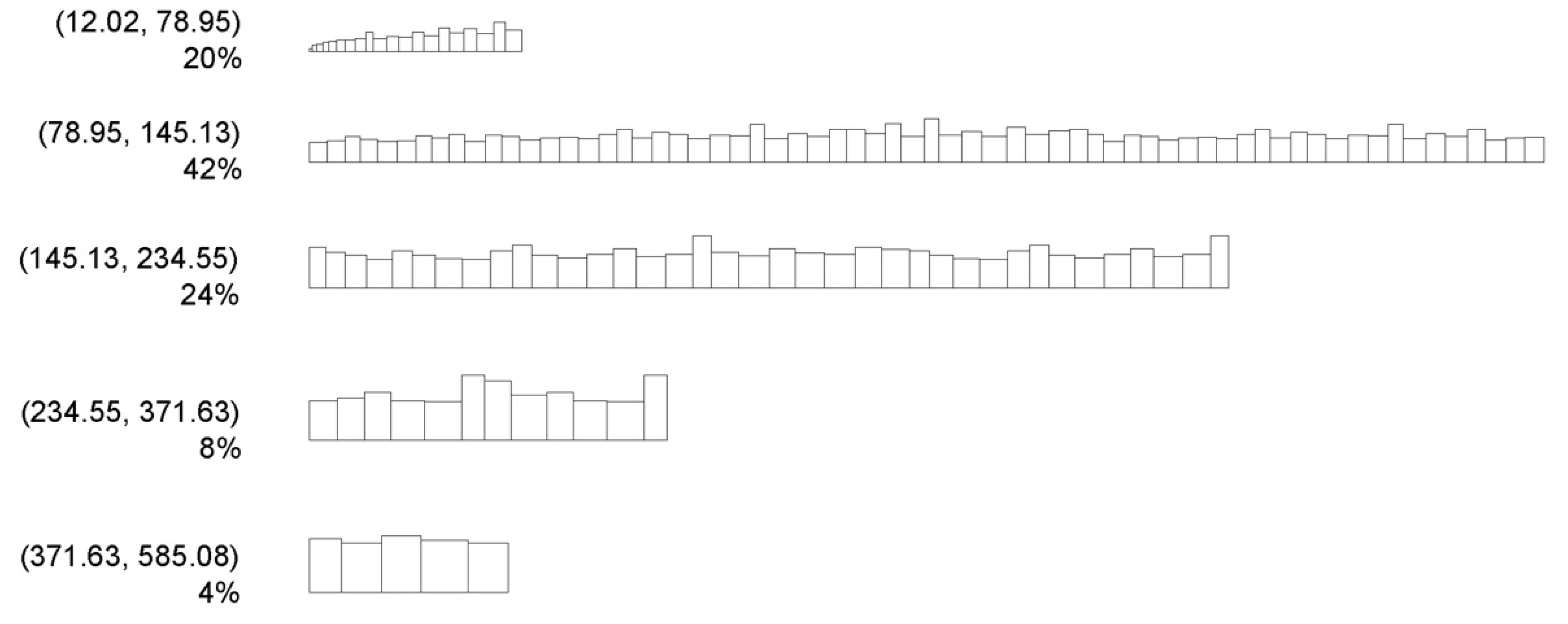
  • Computation of number of buildings (for the sample site and intervals of the six primary characters). Using the cell area (CA) intervals and distribution in the morphometric profile, the total cell areas per interval (TCA) is calculated by multiplying the median value of each interval (M) by the corresponding distribution percentage. The total number of buildings for the sample site is computed by multiplying the site area (A) by 100 (the total of all intervals) and dividing this value by the sum of TCAs. The number of buildings in each interval, for each primary character, is computed by multiplying the distribution percentages for each interval by N and dividing this value by 100.
  • Generation of the building envelopes. To avoid uniformity in figure-grounds, a random set of x values, where x is the number of buildings in each interval computed at the previous step, is generated for each interval for BF and BE. The generated building footprints and elongation values are then randomly matched. Both operations of random number generation can be achieved in Excel via the RAND function, or through ad hoc websites (for example, https://pinetools.com/random-number-generator, accessed on 31 August 2021). The longer dimension (LD) of each building is computed by calculating the square root of the ratio between BF and BE. The shorter dimension (SD) is calculated by dividing BF by LD.
  • Design considerations. Several considerations must be made on the UT around the sample site before laying the buildings on the ground: (i) function and spatial distribution of buildings (i.e., clustered or sparse) and their relations with open spaces; (ii) whether buildings tend to abut on the streets with their short or long sides; (iii) whether the street network tends more to a grid or a tree-like structure. Such considerations are purely qualitative and are made from remote via a quick visual inspection of commonly available map repositories.
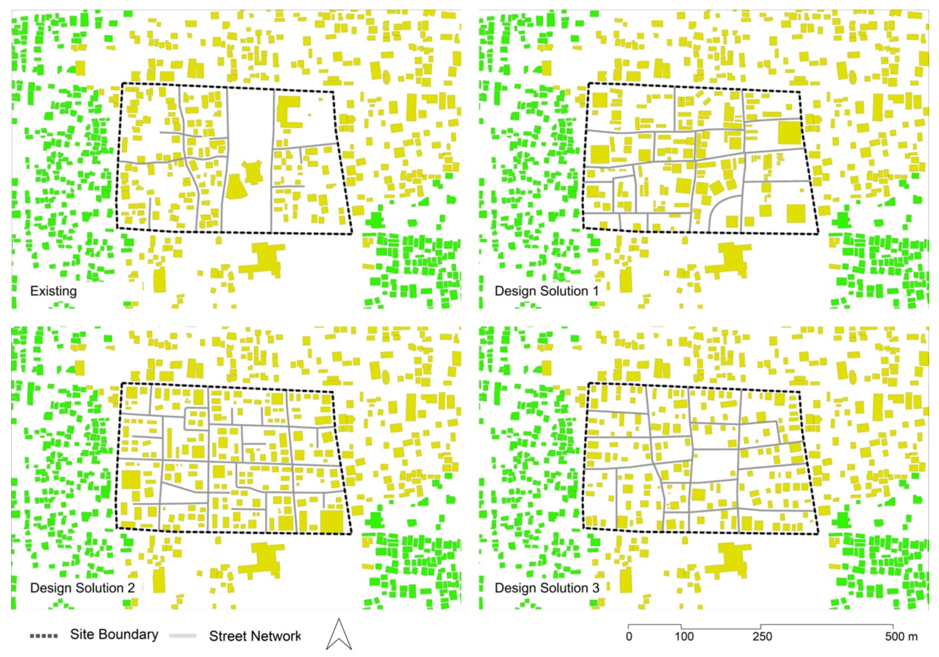
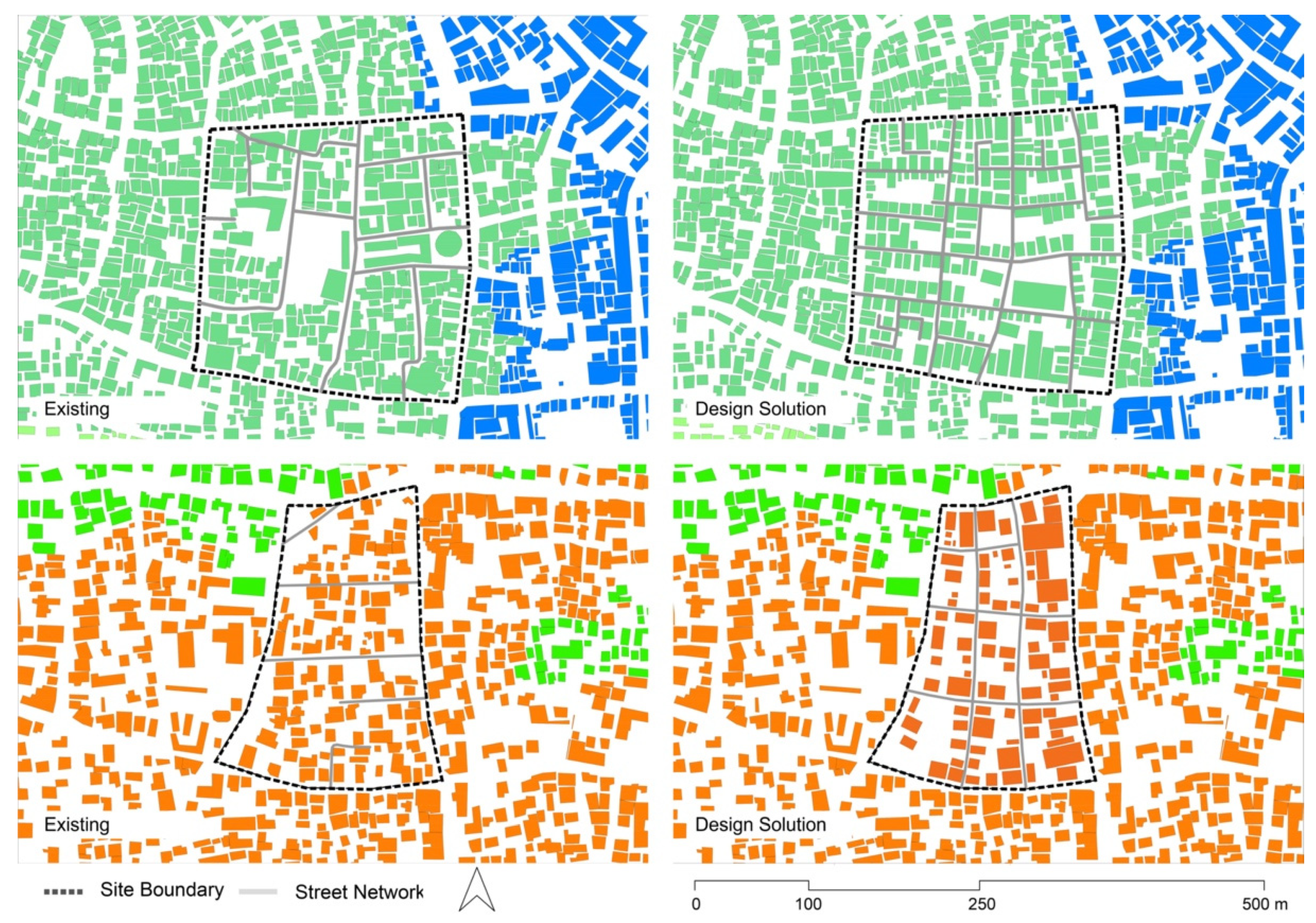
  • Generation of the figure-ground. This is a four step process: (i) in order to maintain and foster the internal connectivity of the sample site as well as that between the sample site and its surroundings, lay down the main street network by continuing the major roads surrounding the site; (ii) start distributing the building envelopes from one side of the site by following the considerations formulated at the previous point; (iii) if necessary, add secondary streets to make each building in the site accessible; (iv) verify whether alignments and distances between buildings correspond to the values of ASB and MDBB.

3. Kochi

Kochi (or Cochin) is a coastal city with a population of 0.67 million [22] in the southern Indian state of Kerala. It is an important port town with tremendous industrial and tourism potentials. It is one of the 100 cities that was selected for the smart city funding from the Government of India [23]. Today’s Kochi consists of the historical Fort Kochi and Mattancherry peninsula, Ernakulam mainland, reclaimed Wellington Island, Bolgatti Island, Vipin island, and several other islands in the estuary of the Vembanad lake, adjoining the Arabian sea.
The great flood of the river Pariyar (1341) resulted in the formation of a new natural harbour. The Kochi state, formed in 1102, shifted its capital to Kochi in 1405 following this flood [24]. By 1440, a large settlement around Mattancherry hosted a wide variety of traders from China to the Middle East, making Kochi an important port town on the southwest coast of India [24]. By 1503, skirmishes between the Portuguese army and the local kingdom resulted in the battle of Kochi, with the Portuguese taking control of the city [25]. In 1665, the Dutch and, by 1795, the British, captured this important port town and controlled the spice trade [25]. By 1814, Kochi became part of the British empire who ruled the town until independence in 1947. During this period, Kochi expanded significantly in its population and area (Figure 2) to its current form.
Kochi today is a strategic port city on the western coast of India. It hosts the headquarters of the southern naval command and the new container terminal of Vallarpadam island that opened in 2011, making it the 4th most productive in the country [27]. Kochi’s predominant economic sectors include IT, tourism, ship-making, spice export, health services, and banking [28]. Even today, the influence and fusion of Arab, Chinese, Portuguese, Dutch, and British periods can be seen in the architecture and culture of the city, with many historical buildings, religious spaces, as well as intangible cultural elements such as foods, traditions, customs, or the practise of different languages in everyday life [29].

4. Dataset, Primary, and Contextual Characters

UMM relies on the input information of two georeferenced datasets: building footprints and street network. However, since reliable information on the latter was missing in Kochi, the methodology was adapted to use only building footprints instead. These were manually drawn in vector format by architecture students at Cardiff University (UK), between October 2020 and January 2021. The area of Kochi considered in this paper (Figure 3) consists of 94,963 buildings. Due to aforementioned data constraints, only 26 of the 74 primary characters of urban form were considered, after exclusion of all those related to streets. For instance, in terms of buildings, footprint areas, elongation, and alignment to neighbouring buildings were measured. In terms of cells, size, coverage ratio, and ratio between number of neighbouring cells and cell perimeter were calculated; 104 contextual characters were then derived from the 26 primary characters by computing their mean, range, Theil index, and Simpson index for local areas up to three topological steps. The 26 primary characters and the 104 contextual characters alongside their median values across the study area are presented in Table A1, in the Appendix A.

5. Results

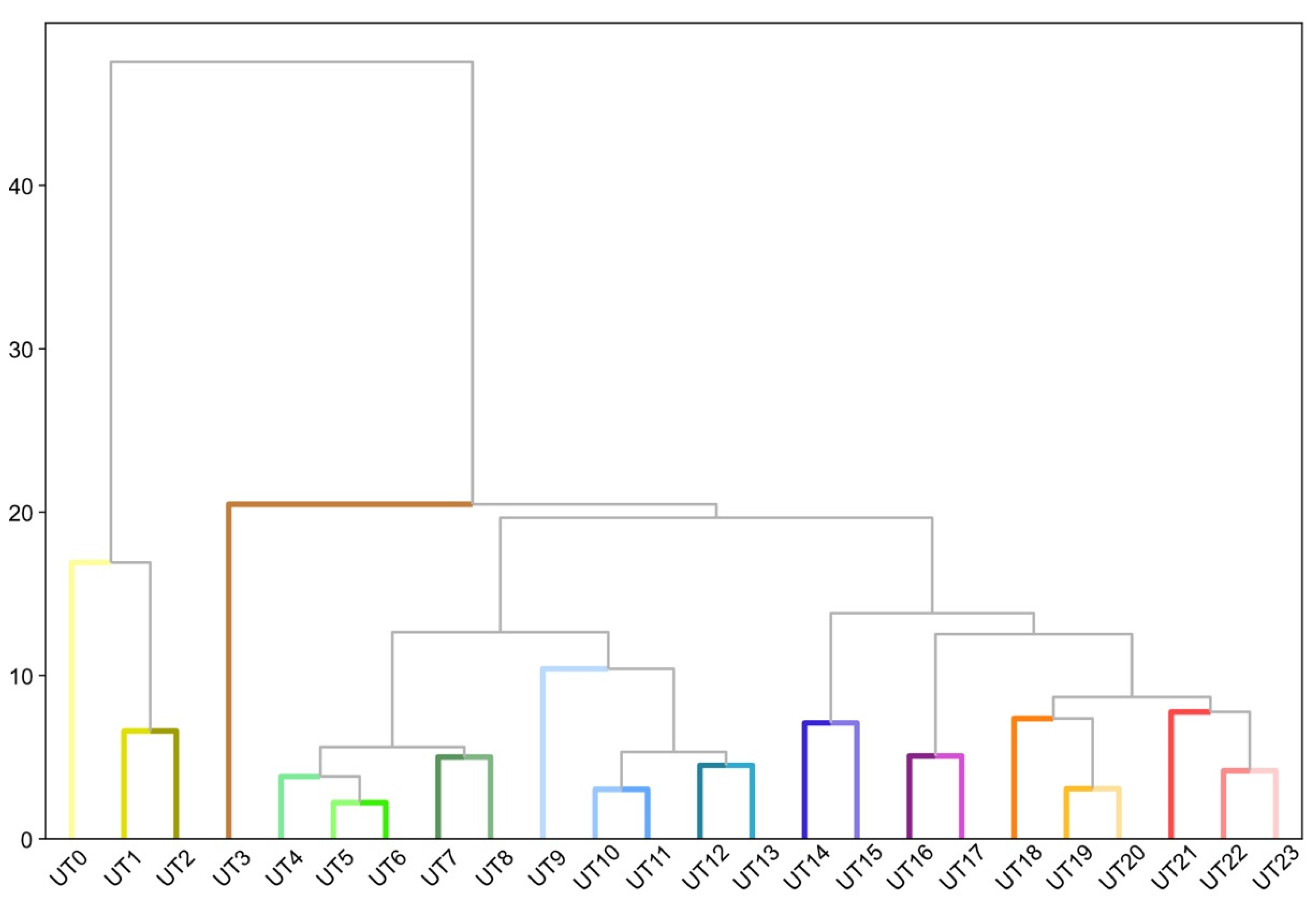
5.1. The Morphometric Taxonomy of Kochi

AHC, with a third order connectivity matrix as spatial constraint, was recursively applied to the 104 contextual characters for solutions up to 25 clusters. The best silhouette score, combining best value with the most detailed classification, was found for 17 clusters (UTs). However, after having mapped this result, two UTs, roughly corresponding to the historical district of Kochi/Mattancherry and Marine Drive were still characterised by considerable morphological heterogeneity. For example, the latter included both the area of the historical Ernakulam Bazaar, characterised by a dense, fine-grained urban fabric, and a newly developed area north-west of the Kerala High Court, which, although being dense, did not have the same granular urban fabric of the former. A second round of agglomerative clustering was thus performed on these two UTs. Through the silhouette score technique, seven clusters (UTs) were found to be the optimal representation of Marine Drive and five in the historical district. By combining this clustering output with the first one, 24 different UTs were identified overall. The unified dendrogram and map of Kochi with buildings colour-coded according to their respective UT and levels of similarity are presented in Figure 4 and Figure 5, respectively; in both figures, a colour-code is attributed to UTs such that each UT is distinctively identified by a different colour, and the more similar the colours, the more similar the urban form.
The 24 UTs seem to align with different phases of urban development of Kochi as well as specific functional areas, providing a first validation of the effectiveness of the process. The most historical part, located in the west peninsula, is largely characterised by UTs in the green shades (e.g., UT6, UT7, UT8). These typically feature a rather uniform, informal urban fabric, with permeable street networks, blocks of regular size, traversed by pedestrian paths, high block, and cell coverage, with small cells and building footprints. Often occupied by makeshift buildings of one storey only, ground floors, especially along main streets, host a range of commercial activities. Streets are often of variable width with several levels feeding into each other. The area of historical warehouses, located around the top of the peninsula, are correctly classified as a separate UT (i.e., UT11): this is mainly characterised by a compact, medium built-up density, one two-storey building on tight cells, aligned to respond to street hierarchy, often hosting public and retail activities on the ground floor. Larger cells and buildings are generally located along main roads and crossings. Blocks are quite regular, with high internal permeability thanks to interconnecting lanes. Willingdon Island (located east of the peninsula hosting the historical core of Kochi) with its mix of military, maritime, and industrial buildings is well represented by UT15: this type is mainly characterised by bulky buildings, a great diversity of cell and building sizes, generally much greater than in any other UTs. Access takes place from main arteries and many cells have direct access to water. It has an unconventional form, ad hoc to function. Kochi mainland has also undergone different phases of urban development and hosts specific functional areas seemingly reflecting the UTs identified through the UMM approach. More precisely, we notice a correspondence between the oldest parts of Kochi mainland, facing the backwaters of the Arabian Sea, dating back to the beginning of the 20th century, and the UTs represented with warm colours. UT21, for example, largely corresponds to the historical area of the Ernakulam Market: it features above-average density, a relatively more chaotic urban fabric, with both compact and elongated buildings mostly not aligned with their respective cells, except in the three main streets of the area (Market street, Broadway, and Jew street). For what concerns more recently developed areas, UT12 seems to capture most of them. It is mainly characterised by a fairly homogeneous, granular, dense urban fabric, often punctuated by large, specialised buildings (e.g., Jawaharlal Nehru Stadium, PVS Memorial Hospital) and infrastructures; here, the former tend to colonise the edges of main urban roads, while ordinary types are independent, compact, medium density buildings, with medium cell coverage and in close proximity to each other, with access from a network of secondary and local streets. Each block has a high permeability due to frequent capillary roads and cul-de-sacs. The orientation of buildings is more regular along main roads, while it breaks down towards the inner parts of blocks.

5.2. Morphometric Profiles of Urban Types in the Historical District of Kochi

Since the research aims at exploring the degree to which (re)-generative figure-ground design demonstrations capture the intangible character of pre-existing urban fabrics, and this is particularly relevant in historical sites, morphometric profiles are generated for three UTs (i.e., UT7, UT18, and UT1) located in the historical district of Fort Kochi/Mattancherry. Intervals for the six primary characters and percentages of buildings falling in each interval for UT7, UT18, and UT1 are provided in Table A2, Table A3 and Table A4, respectively, in the Appendix B. UT7 is characterised by a very fine-grained, relatively dense urban fabric, with most cells (90%) and most buildings (61%) falling in the first interval of their respective distributions, i.e., up to 336.1 m2 and up to 79 m2, respectively. Coverage ratios tend to be more evenly distributed, however, the intervals with more observations (those with more than 10% of them) have values around 0.50 (i.e., 50% cell coverage). Mean distances and alignments between neighbouring buildings tend also to be very small: 46% of buildings are located between 0.1 and 3.7 m from their nearest neighbours and tend to align with them, most buildings diverging only between 1.4 and 4.8 degrees. In terms of elongation, buildings of UT7 show values evenly distributed across intervals, corresponding to a mix of building footprints, from squares to elongated rectangles.
The morphometric profile of UT18 suggests a slightly coarser and less dense urban fabric, with roughly half of the cells falling in the first interval (up to 336.1 m2) and 34% being in the second one (i.e., between 336.1 and 650.9 m2). Building footprints follow a similar pattern, with most (40%) concentrating in the second interval, i.e., between 79 and 145.1 m2. Cells of UT18 tend also to be less built-up than in UT7, with most concentrating in intervals with coverage ratios between 0.29 and 0.47, corresponding to a coverage of 29% and 47%, respectively. As in UT7, buildings tend to be close to each other, 62% are less than 8.3 m away from their respective neighbours, and aligned with them, 77% diverge for 4.8 degrees or less. Finally, building footprints of UT18 tend to be more square-shaped than rectangular, with most observations falling into the top seven intervals.
UT1 is the least dense and coarsest of the three, with most cells (36%) measuring between 336.1 and 651 m2, and most building footprints (42%) measuring between 79 to 145 m2. Coverage ratios tend to be lower than in UT7, with most values (intervals with more than 10% of observations each) concentrating between 0.11 and 0.33, i.e., 11% and 33% cell coverage, respectively. Mean distances between buildings tend also to be slightly larger than in UT7, with most being distant from 3.7 to 17.3 m with respect to their neighbours. On the other hand, buildings tend to be more aligned with each other than in UT7, with most (41%) diverging between 0 and 1.4 degrees. In terms of elongation, building footprints tend to be more square-shaped, with most values concentrating in the top intervals of the distribution.

5.3. Producing Figure-Grounds in Sample Sites

In this section, we present three figure-ground design demonstrations in sample sites that belong to UT1, UT7, and UT18. The first is illustrated in detail, including the process that generates building envelopes from the morphometric profile. The other two applications are purely demonstrative and showcase one design solution for each UT. Since at the time of writing the article, no development areas were officially identified in the district Fort Kochi/Mattancherry, the demonstrations are purely abstract and the only discriminant for the selection of the sample sites is the size (not less than 100 buildings as explained in the Methodology section).
The sample site in UT1 exhibits 140 buildings and has an area (A) of 114,541.7 m2. It is delimited by Jawahar road to the north, Santo Gopalan road to the east, Cochin College road to the south, and Pandikudy road to the west (Figure 7, top left). After removing the existing fabric, three of the four UNICITI designers involved in the development of the workflow set out to develop, independently, a design iteration each for the site.
To do so, intervals and distribution percentages of CA (Table A2, Appendix B) were used to compute the sum of TCAs (Table 1) and the total number of buildings (171) for the sample site by multiplying A by 100 (the total of all intervals) and dividing this value by the sum of TCAs (66,958 m2). Having obtained this datum, the number of buildings for each interval, for each of the six primary characters, were then calculated (see Table 2, as an example for BF). Random values were then generated for each interval and primary character, to obtain the actual dimensions of the building envelopes that will populate the site. Values of BF and BE were then randomly matched to avoid uniformity in the new urban fabric, and longer (LD) and shorter dimensions (SD) for each building were subsequently computed. Figure 6 shows the resulting building envelopes for the selected sample site, with intervals and distribution percentages of BF.
By visually inspecting the main spatial characteristics of UT1, the three UNICITI designers then produced the following design observations to guide the positioning of the building envelopes on the site. UT1 is characterised by both relatively small buildings in close proximity, constituting the majority of the ordinary urban fabric of this UT, and isolated specialised ones, often surrounded by open space. Both types of buildings tend to abut on nearby streets from which they are accessed with their shortest sides. The existing street network is relatively regular and well connected, tending more to a grid than a tree-like structure. Along main streets, especially those pointing towards landmarks, cell, and building alignments, are more regular. These observations, together with the last step of the methodology, were then used by the UNICITI designers to independently generate three figure-ground assemblages (Figure 7, top right, bottom left, bottom right) for the sample site (Figure 7, top left). Starting from re-connecting the street network, around and through the site, using the context as guidance of local practice, they followed with arranging buildings along main streets and spaces, and adding secondary streets. The results show how a similar urban character was achieved, but in three distinctive attempts, all considerate of the existing contextual character. This suggests that, as a design aid, the morphometric analysis combined to the workflow were effective in generating urban fabrics structurally similar, but not identical to that typical of UT1.
To demonstrate the capability of the workflow, two further exercises of figure-ground generation for UT7 and UT18 are presented in Figure 8. Note that, this time, for matter of brevity, calculations are omitted. The sample site in UT7 is delimited by Eraveli Road to the north, Mohammad Abdul Rahaman Road to the east, Pullupalam Road to the south, and Chakkara Idukku Road to the west. The sample site in UT18 is delimited by Kocheri road to the north, Mary Auso Vaidhyar Road to the east, Pt Joseph road to the south, and Nazareth road to the west. Just out of a visual assessment, the design outputs (Figure 8, top right and bottom right) seem to confirm the ability of the proposed approach of producing new urban fabrics in line with the character and uniqueness of existing ones (Figure 8, top left and bottom left).

6. Discussion

In terms of significance of the results, as a design tool, UMM generates typical iterations for selected UTs. Importantly, the workflow leads to the formation of figure-grounds in terms of building envelopes, hence not in terms of real shape nor function. It needs to be reiterated that although UMM can potentially provide useful information to inform a new generation of evidence-based design codes (EBDCs), this potential, as such, is not explored here. At this stage, we are presenting a design demonstration whose subject matter is a fairly reduced proxy of what can be obtained from a full UMM application, in particular, because of data limitations (we are working with 26 out of 74 primary characters of urban form), which do not include any information on streets and building heights. In short, UMM is run on building footprint information alone. As a result, the UTs are identified on the ground of only 104 out of the full set of 296 contextual descriptors normally utilised with optimal input data. Understanding the degree of quality of UMM’s output under such largely sub-optimal input conditions was also a reason why we embarked in the study of Kochi in the first place.
In terms of validation, notwithstanding these aforementioned constraints, after a detailed validation (see Section 5.1) conducted with students and staff of Cardiff University, experts with direct experience of the place, against Kochi’s urbanisation history and mainland-uses’ distribution, we do observe that the resulting taxonomy seems to capture the main characters of the real city to a surprising degree. This gave considerable support to the outputs. However, a systematic process of validation against other layers of social, economic, and environmental information will require further investigation.
In terms of relevance of the proposed methodology and results, UMM-based numerical design guidelines seem to be effective in helping distinct designers towards delivering design outputs that both capture the intangible essential quality that makes for the unique identity of historical UTs of Kochi and yet remain clearly distinguishable from each other. Most importantly, this ability shows up: (i) out of an application based on sub-optimal input data; (ii) over the design of figure-ground building envelopes only, and (iii) across different demonstrations both delivered by different designers over the same UT and by the same designer over different UTs. In all evidence, this potential is particularly interesting when applied in historical/heritage areas, where morphological assets are recognisably associated with deep local socio-cultural contexts and fragile values of place identity, hence continuity with such traits is particularly valuable. However, we would like to stress the importance for Asian cities not only to preserve their current heritage from their valuable past, but also to build today the heritage of their equally valuable future. Stating this means highlighting the importance to learn the essential nature of the past we still treasure to link it up to the present we operate in. A nearly madly ambitious task, to be true, which certainly cannot be reduced to the physical structure of spaces and must involve the forms of city production, its governance and industrial management, its equity and political viability. As per the master planning process alone, it is our ambition, in this paper, to account for an innovation of technical nature that we believe can promote helpful progress in many aspects of urban (heritage) planning. Most importantly, such innovations could potentially impact on the other—and often neglected—side of the medal, which involves the informal settlements of today and tomorrow, along with slums’ community protagonism in their production and development in time. Further site analyses and considerations should be carried out to gather more context-based knowledge, which is fundamental to transform figure-ground envelopes through the workflow, helping to define their architectural styles, their relations with private/public spaces, street sections, and surfaces. The workflow for figure-ground generation must also be adapted to reflect possible constraints dictated by local design briefs. The first application of the workflow shows a range of alternatives, none of which is identical to the existing one nor between each other, but all are close to it in terms of figure-ground, character, and circulation showing that we are in the position to generate urban fabric from a limited set of input data which is similar in substance to the original one, but not identical to it. This overcomes a frequent criticism of generative design, perceived as deterministic or acritical. The proposed workflow can be a powerful, evidence-based tool in the hands of designers who want to capture and reproduce the essential character of a place, in fact, any place that makes sense to them as well as the communities involved in the process. This does not mean to reproduce acritically design solutions, but to replicate the structural spatial patterns that have proven an ability to develop, in time, qualities which are considered valuable assets in current society. Such quality should not be reduced to aesthetic ones, but, in fact, involve quality of adaptability in time, hence resilience, flood recovery, support to healthy lifestyle, and walkable access to basic services, etc. This preliminary demonstration suggests that the combination of UMM and a new generation of EBDCs could inform a positive development of the BAU way of building towards a more sensitive and locally responsive urban development framework while, at the same time, keeping it responsive to current requirements, standards and needs. It is also an alternative to niche, context-based, but small-scale developments as the approach is replicable and scalable and can thus be applied to cities and project sites of virtually any size. It can be effective in situations characterised by limited resources, difficult operative conditions, political instability, and widespread informal practices. By providing an established background of knowledge (of UTs and their effectiveness in their context) and flexible spatial proposals, it can also help to retain overall quality control while, at the same time, allowing for the co-production of space. One natural avenue to exploit the potential of UMM towards this Third Way for Asian Cities is testing DCs based on a rigorous, replicable, scalable, and comprehensive science of urban form. Such science is by no means mature but is now rapidly expanding with and beyond the proposed UMM method. The implications on policy are many and currently under development in forthcoming publications.
In terms of limitations, we acknowledge three main ones. First, while the clustering process to identify UTs is unsupervised, the selection of the optimal number of UTs is based on a heuristic method (i.e., the silhouette score), leaving space to interpretation. Kochi might thus be defined by a different number of UTs. Nonetheless, having tested different clustering solutions and comparing them to phases of urban development and existing functional areas, we believe 24 to be a faithful representation of the different urban fabrics of the city. A second limitation concerns the presence of outliers in the data (e.g., too small BFs). Due to the size of the input dataset, these might go unnoticed, creating a partially biased representation of specific intervals in the morphometric profiles. If that is the case, the morphometric profiles containing outliers can be used to identify them and correct or filter the input dataset. A third limitation is inherent to scalability: a first-hand, accurate, human-based site survey cannot be replaced by any unsupervised morphometric procedure, and, in fact, it should not. UMM should be seen as a large-scale applicable ecosystem whose best use is in conjunction with local, project-specific, and community-based surveys, or, in fact, the development of project-languages along the human-based tradition mastered, for example, in Alexander’s pattern language work [30,31].

7. Conclusions

Asian cities are developing exceptionally fast. How we guide and support such development is crucial, for those living in it, for the planet, for both environmental, cultural, and economic reasons. The BAU mode has already compromised the physical and social significance of many urban environments, with forms which are incompatible under many points of view. On the other hand, niche and more sustainable ways of building can embed local cultural contexts, however, they are not capable of coping with the large demand for new housing. This context calls for an alternative which can simultaneously ensure quantity, affordability and, at the same time, respond to the need of building unique cities which embed local cultural values. In this paper, to address this challenge, we proposed a replicable and scalable methodology to: (i) detect morphological uniqueness in cities via the identification of homogeneous patterns of urban form (UTs); (ii) extract morphometric profiles for target UTs; (iii) input this information in a workflow for the generation of new urban fabrics aligned with the character and uniqueness of their respective UTs. The proposed methodology was applied to the city of Kochi, where 24 different UTs were identified, seemingly matching historical-functional patterns. Three morphometric profiles were generated for UTs located in the historical district of Fort Kochi/Mattancherry and used as inputs for figure-ground generation. The outputs showed that, by using the same workflow, it is not only possible to produce urban fabrics aligned with the morphological character of their respective UTs, but also produce different design solutions for the very same sample site. The combination of morphometric analysis and workflow for figure-ground generation can contribute to the production of context-based design in historical/heritage areas and, more broadly, to the above-mentioned Third Way of Building Asian Cities, by providing a scalable and systemic way of identifying the unique character of different city parts and producing design outputs aligned with such uniqueness. While this approach has been presented in relation to the rapid urbanisation in Asia, it is still replicable in virtually any place in the world, provided that, at least, data on buildings are available.

Author Contributions

Conceptualisation, A.V., O.R. and S.P.; Methodology, A.V., O.R., S.P., K.K., N.B., V.V. and S.U.; Software, A.V.; Validation, A.V., O.R., S.P. and S.R.; Formal analysis, A.V., O.R., K.K. and N.B.; Investigation, A.V., K.K., N.B., V.V., S.U. and S.R.; Data curation, A.V., K.K. and N.B.; Writing—Original Draft Preparation, A.V., O.R., O.C., S.P. and S.R.; Writing—Review and Editing, A.V., O.R. and S.P.; Visualisation, A.V., K.K. and N.B.; Supervision, A.V., O.R. and S.P.; Project Administration, A.V.; Funding acquisition, S.P. All authors have read and agreed to the published version of the manuscript.

Funding

This research was funded by the Axel and Margaret Ax:son Johnson Foundation, grant number GEN2971-100.

Conflicts of Interest

The authors declare no conflict of interest.

Appendix A

Table A1. The 26 primary characters and 104 contextual characters with their median values across the study area.
Primary CharacterElementFormulaContextual
Character
Median
FootprintBuildingablgmean124.1678
range93.3752
Theil index0.0868
Simpson index0.4644
PerimeterBuildingpblgmean46.1862
range18.5704
Theil index0.0251
Simpson index0.4094
Courtyard areaBuildingablgcmean0.0000
range0.0000
Theil index0.0000
Simpson index1.0000
Cardinal orientationBuildingOriblg = |OblgB − 45| mean12.2051
range6.4277
Theil index0.0489
Simpson index0.2978
Cell alignmentBuilding C A l b l g = | O r i b l g O r i c e l l | mean6.4250
range9.7176
Theil index0.2585
Simpson index0.5192
Circular compactnessBuilding C C o b l g = a b l g a b l g C mean0.5561
range0.0996
Theil index0.0049
Simpson index0.2056
CornersBuilding C or b l g   =   i = 1 n C b l g mean4.0000
range0.5000
Theil index0.0171
Simpson index0.5946
SquarenessBuilding S q u b l g = i = 1 n D c b l g i n mean3.3104
range3.4466
Theil index0.1722
Simpson index0.6333
Equivalent rectangular indexBuilding ERI b l g = a b l g a b l g B P b l g B P b l g mean0.9959
range0.0168
Theil index0.0003
Simpson index0.6307
ElongationBuilding E l o b l g = l b l g B w b l g B mean0.7162
range0.2668
Theil index0.0180
Simpson index0.1834
Centroid-corner distance deviationBuilding C C D b l g = 1 n i = 1 n ( c c d i c c d ¯ ) 2 mean0.2971
range0.6086
Theil index0.4551
Simpson index0.5749
Centroid-corner mean distanceBuilding C C M b l g = 1 n ( i = 1 n c c d i ) mean7.9237
range2.9362
Theil index0.0207
Simpson index0.3981
AreaCellacellmean457.3075
range403.0552
Theil index0.1043
Simpson index0.7593
Cardinal orientationCell O r i c e l l = | o c e l l B 45 | mean15.8594
range13.9275
Theil index0.1125
Simpson index0.2255
Weighted neighboursCell W N e c e l l =   c e l l n p c e l l mean0.0685
range0.0254
Theil index0.0179
Simpson index0.4150
Coverage ratioCell C A R c e l l = a b l g a c e l l mean0.3127
range0.1811
Theil index0.0464
Simpson index0.2180
Circular compactnessCell C C o c e l l = a c e l l a c e l l C mean0.5232
range0.1452
Theil index0.0104
Simpson index0.1742
Equivalent rectangular indexCell E R I c e l l = a c e l l a c e l l B * p c e l l B p c e l l mean0.9890
range0.0660
Theil index0.0006
Simpson index0.4214
Perimeter wall lengthAdjacent buildings p b l g a d j mean47.1169
range19.6771
Theil index0.0283
Simpson index0.4360
Shared walls’ ratioAdjacent buildings S W R b l g = p b l g s h a r e d p b l g mean0.0000
range0.0000
Theil index2.0809
Simpson index1.0000
Number of courtyardsAdjacent buildings N C o b l g a d j mean0.0000
range0.0000
Theil index0.0000
Simpson index1.0000
AlignmentNeighbouring buildings A l i b l g = 1 n i = 1 n | O r i b l g O r i b l g i | mean4.0671
range2.6006
Theil index0.0541
Simpson index0.5052
Mean distanceNeighbouring buildings N D i b l g = 1 n i = 1 n d b l g , b l g i mean9.3790
range7.0551
Theil index0.0729
Simpson index0.6777
Mean inter-building distanceNeighbouring buildings I B D b l g = 1 n i = 1 n d b l g , b l g i mean11.1417
range2.5860
Theil index0.0074
Simpson index1.0000
Building adjacencyNeighbouring buildings B u A b l g =   b l g a d j   b l g mean1.0000
range0.0000
Theil index0.0000
Simpson index0.6859
Area coveredNeighbouring cells a c e l l n = i = 1 n a c e l l i mean3917.0594
range2540.8757
Theil index0.0556
Simpson index0.7752

Appendix B

Table A2. Morphometric profile of UT1.
CA
Intervals
% CellsCR
Intervals
% CellsBF
Intervals
% BuildingsBE
Intervals
% BuildingsASB
Intervals
% BuildingsMDBB
Intervals
% Buildings
(24.60, 336.09)29.70(0.01, 0.06)1.26(12.02, 78.95)20.15(0.07, 0.20)0.59(0.00, 1.43)40.59(0.82, 3.67)4.30
(336.09, 650.88)36.59(0.06, 0.11)5.63(78.95, 145.13)42.00(0.20, 0.31)1.93(1.43, 2.31)20.59(3.67, 5.95)12.81
(650.88, 1080.39)20.22(0.11, 0.16)11.63(145.13, 234.55)24.07(0.31, 0.39)3.78(2.31, 3.12)12.07(5.95, 8.33)17.04
(1080.39, 1677.60)9.33(0.16, 0.20)12.30(234.55, 371.63)8.30(0.39, 0.46)5.33(3.12, 3.95)8.15(8.33, 10.96)17.85
(1677.60, 2515.36)2.89(0.20, 0.25)10.89(371.63, 585.08)3.56(0.46, 0.52)5.33(3.95, 4.83)5.70(10.96, 13.91)17.11
(2515.36, 3689.55)0.59(0.25, 0.29)12.37(585.08, 910.02)0.59(0.52, 0.57)8.52(4.83, 5.78)4.74(13.91, 17.34)10.96
(3689.55, 5266.39)0.37(0.29, 0.33)11.70(910.02, 1430.61)0.81(0.57, 0.62)6.59(5.78, 6.84)2.44(17.34, 21.52)9.56
(5266.39, 7385.03)0.07(0.33, 0.38)9.56(1430.61, 2212.47)0.30(0.62, 0.66)6.81(6.84, 8.06)1.93(21.52, 26.72)6.59
(7385.03, 10,282.65)0.07(0.38, 0.42)8.74(2212.47, 3423.68)0.07(0.66, 0.71)7.11(8.06, 9.53)1.41(26.72, 33.26)2.30
(10,282.65, 14,106.60)0.00(0.42, 0.47)5.85(3423.68, 5308.78)0.07(0.71, 0.75)8.37(9.53, 11.39)0.89(33.26, 41.53)1.04
(14,106.60, 19,523.60)0.15(0.47, 0.51)4.00(5308.78, 7792.22)0.07(0.75, 0.80)7.63(11.39, 13.81)0.59(41.53, 52.31)0.30
(19,523.60, 26,922.44)0.00(0.51, 0.56)3.48(7792.22, 10,715.89)0.00(0.80, 0.85)7.56(13.81, 17.03)0.37(52.31, 67.13)0.07
(26,922.4, 35,608.03)0.00(0.56, 0.63)1.56(10,715.8, 14,611.60)0.00(0.85, 0.90)9.85(17.03, 21.37)0.22(67.13, 87.98)0.07
(35,608.0, 48,659.49)0.00(0.63, 0.71)0.89(14,611.6, 26,037.39)0.00(0.90, 0.95)10.07(21.37, 27.66)0.15(87.98, 118.10)0.00
(48,659.4, 67,909.16)0.00(0.71, 1.34)0.15(26,037.3, 34,898.16)0.00(0.95, 1.00)10.52(27.66, 40.37)0.15(118.10, 199.79)0.00
Table A3. Morphometric profile of UT7.
CA
Intervals
% CellsCR
Intervals
% CellsBF
Intervals
% BuildingsBE
Intervals
% BuildingsASB
Intervals
% BuildingsMDBB
Intervals
% Buildings
(24.60, 336.09)89.54(0.02, 0.06)0.45(12.02, 78.95)61.39(0.09, 0.20)0.76(0.27, 1.43)8.46(0.11, 3.67)45.90
(336.09, 650.88)9.14(0.06, 0.11)1.36(78.95, 145.13)29.35(0.20, 0.31)2.64(1.43, 2.31)19.38(3.67, 5.95)27.01
(650.88, 1080.39)0.91(0.11, 0.16)2.38(145.13, 234.55)7.03(0.31, 0.39)5.89(2.31, 3.12)18.47(5.95, 8.33)15.49
(1080.39, 1677.60)0.26(0.16, 0.20)3.48(234.55, 371.63)1.51(0.39, 0.46)7.67(3.12, 3.95)15.64(8.33, 10.96)6.35
(1677.60, 2515.36)0.11(0.20, 0.25)4.38(371.63, 585.08)0.45(0.46, 0.52)7.40(3.95, 4.83)10.43(10.96, 13.91)3.02
(2515.36, 3689.55)0.04(0.25, 0.29)6.16(585.08, 910.02)0.19(0.52, 0.57)7.67(4.83, 5.78)8.08(13.91, 17.34)1.32
(3689.55, 5266.39)0.00(0.29, 0.33)7.22(910.02, 1430.61)0.08(0.57, 0.62)7.74(5.78, 6.84)6.23(17.34, 21.52)0.76
(5266.39, 7385.03)0.00(0.33, 0.38)7.44(1430.61, 2212.47)0.00(0.62, 0.66)8.88(6.84, 8.06)4.57(21.52, 26.72)0.11
(7385.03, 10,282.65)0.00(0.38, 0.42)10.09(2212.47, 3423.68)0.00(0.66, 0.71)7.78(8.06, 9.53)3.97(26.72, 33.26)0.04
(10,282.6, 14,106.60)0.00(0.42, 0.47)10.05(3423.68, 5308.78)0.00(0.71, 0.75)7.56(9.53, 11.39)2.61(33.26, 41.53)0.00
(14,106.6, 19,523.60)0.00(0.47, 0.51)10.80(5308.78, 7792.22)0.00(0.75, 0.80)6.91(11.39, 13.81)0.94(41.53, 52.31)0.00
(19,523.6, 26,922.44)0.00(0.51, 0.56)11.41(7792.22, 10,715.89)0.00(0.80, 0.85)6.72(13.81, 17.03)0.72(52.31, 67.13)0.00
(26,922.4, 35,608.03)0.00(0.56, 0.63)12.05(10,715.8, 14,611.60)0.00(0.85, 0.90)8.20(17.03, 21.37)0.23(67.13, 87.98)0.00
(35,608.0, 48,659.49)0.00(0.63, 0.71)9.52(14,611.6, 26,037.39)0.00(0.90, 0.95)7.40(21.37, 27.66)0.19(87.98, 118.10)0.00
(48,659.4, 67,909.16)0.00(0.71, 1.34)3.21(26,037.3, 34,898.16)0.00(0.95, 1.00)6.76(27.66, 40.37)0.08(118.10, 199.79)0.00
Table A4. Morphometric profile of UT18.
CA
Intervals
% CellsCR
Intervals
% CellsBF
Intervals
% BuildingsBE
Intervals
% BuildingsASB
Intervals
% BuildingsMDBB
Intervals
% Buildings
(41.18, 336.09)51.15(0.05, 0.06)0.27(12.02, 78.95)27.21(0.05, 0.20)0.35(0.49, 1.43)8.57(0.80, 3.67)12.28
(336.09, 650.88)33.66(0.06, 0.11)1.15(78.95, 145.13)39.75(0.20, 0.31)1.06(1.43, 2.31)20.49(3.67, 5.95)22.70
(650.88, 1080.39)11.66(0.11, 0.16)2.92(145.13, 234.55)20.14(0.31, 0.39)3.89(2.31, 3.12)20.76(5.95, 8.33)27.03
(1080.39, 1677.60)2.65(0.16, 0.20)6.45(234.55, 371.63)9.63(0.39, 0.46)6.01(3.12, 3.95)15.72(8.33, 10.96)18.64
(1677.60, 2515.36)0.71(0.20, 0.25)7.51(371.63, 585.08)2.56(0.46, 0.52)7.07(3.95, 4.83)11.57(10.96, 13.91)11.57
(2515.36, 3689.55)0.09(0.25, 0.29)9.36(585.08, 910.02)0.62(0.52, 0.57)6.80(4.83, 5.78)6.27(13.91, 17.34)4.33
(3689.55, 5266.39)0.09(0.29, 0.33)14.84(910.02, 1430.61)0.09(0.57, 0.62)6.71(5.78, 6.84)5.48(17.34, 21.52)2.03
(5266.39, 7385.03)0.00(0.33, 0.38)14.22(1430.61, 2212.47)0.00(0.62, 0.66)8.83(6.84, 8.06)3.89(21.52, 26.72)0.97
(7385.03, 10,282.65)0.00(0.38, 0.42)12.54(2212.47, 3423.68)0.00(0.66, 0.71)9.10(8.06, 9.53)3.36(26.72, 33.26)0.18
(10,282.65, 14,106.60)0.00(0.42, 0.47)11.57(3423.68, 5308.78)0.00(0.71, 0.75)9.01(9.53, 11.39)1.41(33.26, 41.53)0.09
(14,106.60, 19,523.60)0.00(0.47, 0.51)8.92(5308.78, 7792.22)0.00(0.75, 0.80)9.63(11.39, 13.81)0.71(41.53, 52.31)0.09
(19,523.60, 26,922.44)0.00(0.51, 0.56)4.59(7792.22, 10,715.89)0.00(0.80, 0.85)7.42(13.81, 17.03)0.62(52.31, 67.13)0.09
(26,922.44, 35,608.03)0.00(0.56, 0.63)3.18(10,715.89, 14,611.60)0.00(0.85, 0.90)8.48(17.03, 21.37)0.27(67.13, 87.98)0.00
(35,608.03, 48,659.49)0.00(0.63, 0.71)1.77(14,611.60, 26,037.39)0.00(0.90, 0.95)7.69(21.37, 27.66)0.44(87.98, 118.10)0.00
(48,659.49, 67,909.16)0.00(0.71, 1.34)0.71(26,037.39, 34,898.16)0.00(0.95, 1.00)7.95(27.66, 40.37)0.44(118.10, 199.79)0.00

References

  1. 2020 E-Handbook of Statistics. Total and Urban Population. Available online: https://stats.unctad.org/handbook/Population/Total.html (accessed on 31 August 2021).
  2. United Nations (UN). The Sustainable Development Goals Report 2021; United Nations (UN): New York, NY, USA, 2021; p. 48. [Google Scholar]
  3. TERI; Development Alternatives; GIZ. Material Consumption Patterns in India: A Baseline Study of the Automotive and Construction Sectors; Deutsche Gesellschaft für Internationale Zusammenarbeit (GIZ): New Delhi, India, 2016. [Google Scholar]
  4. Global Infrastructure Basel Summit. Available online: https://www.gn-sec.net/news/global-infrastructure-basel-summit (accessed on 31 August 2021).
  5. Chepelianskaia, O. Why Should Asia Build Unique Cities? In Beyond the Metropolis, Proceedings of the 55th ISOCARP World Planning Congress 2019, Jakarta, Indonesia, 9–13 September 2019; Juvara, M., Ledwon, S., Eds.; ISOCARP: The Hague, The Netherlands, 2019. [Google Scholar]
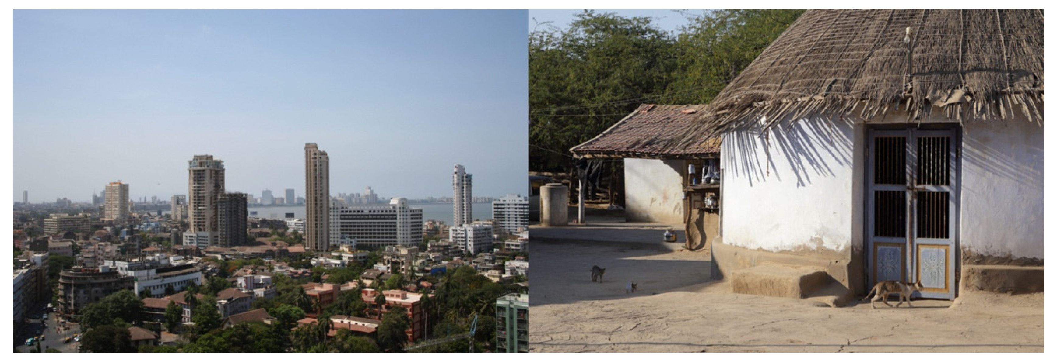
  6. Downtown from Nana Chowk. Aam422, CC BY-SA 3.0. Available online: https://commons.wikimedia.org/wiki/Mumbai#/media/File:Bombay1.jpg (accessed on 17 November 2021).
  7. Zaveri, N. Trespassers, Dhordo. CC BY 2.0. Available online: https://flic.kr/p/TZYX22 (accessed on 17 November 2021).
  8. Christensen, J.M.; Olhoff, A. Emissions Gap Report 2019; United Nations Environment Programme (UNEP): Gigiri Nairobi, Kenya, 2019. [Google Scholar]
  9. NESEA Blog. The All-Glass Building. Is Energy Efficiency Possible? Available online: https://nesea.org/conversation/masters-blog/all-glass-building (accessed on 31 August 2021).
  10. The Life Expectancy of Buildings. Available online: https://brandondonnelly.com/2015/09/06/the-life-expectancy-of-buildings/ (accessed on 31 August 2021).
  11. Clark, G.; Moonen, T.; Couturier, T. Globalisation and Competition: The New World of Cities; Cities Research Center: Chicaco, IL, USA, 2015. [Google Scholar]
  12. The Economist Intelligence Unit. The Global Liveability Index 2021. How the COVID-19 Pandemic Affected Liveability Worldwide; The Economist: London, UK, 2021; p. 4. [Google Scholar]
  13. Fleischmann, M.; Feliciotti, A.; Romice, O.; Porta, S. Methodological Foundation of a Numerical Taxonomy of Urban Form. arXiv 2021, arXiv:2104.14956. [Google Scholar]
  14. Legendre, P. Spatial autocorrelation: Trouble or new paradigm? Ecology 1993, 74, 1659–1673. [Google Scholar] [CrossRef]
  15. Nubani, L.; Wineman, J. The role of Space Syntax in identifying the relationship between space and crime. In Proceedings of the 5th Space Syntax symposium on Space Syntax, Delft, The Netherlands, 13–17 June 2005. [Google Scholar]
  16. Omer, I.; Goldblatt, R. Spatial patterns of retail activity and street network structure in new and traditional Israeli cities. Urban Geogr. 2016, 37, 629–649. [Google Scholar] [CrossRef]
  17. Fleischmann, M.; Romice, O.; Porta, S. Measuring urban form: Overcoming terminological inconsistencies for a quantitative and comprehensive morphologic analysis of cities. Environ. Plan. B Urban Anal. City Sci. 2020, 48, 2133–2150. [Google Scholar] [CrossRef] [Green Version]
  18. Fleischmann, M.; Feliciotti, A.; Romice, O.; Porta, S. Morphological tessellation as a way of partitioning space: Improving consistency in urban morphology at the plot scale. Comput. Environ. Urban Syst. 2020, 80, 101441. [Google Scholar] [CrossRef]
  19. Rokach, L.; Maimon, O. Clustering methods. In Data Mining and Knowledge Discovery Handbook; Maimon, O., Rokach, L., Eds.; Springer: Boston, MA, USA, 2005; pp. 321–352. [Google Scholar]
  20. Rousseeuw, P.J. Silhouettes: A graphical aid to the interpretation and validation of cluster analysis. J. Comput. Appl. Math. 1987, 20, 53–65. [Google Scholar] [CrossRef] [Green Version]
  21. Ministry of Housing, Communities and Local Government. National Model Design Code; Crown: London, UK, 2021. [Google Scholar]
  22. Directorate of Census Operations of Kerala. District Census Handbook Ernakulam: Village and Town Wise Primary Census Abstract (PCA); Government of India: New Dehli, India, 2011. [Google Scholar]
  23. Ministry of Housing and Urban Affairs. Smart Cities; Government of India: New Delhi, India, 2021. [Google Scholar]
  24. Menon, K.P.P. Kochi Rajya Charithram; Mathrubhumi Books: Thiruvananthapuram, India, 1989. [Google Scholar]
  25. Logan, W. Malabar Manual; Asian Educational Services: New Delhi, India, 2000. [Google Scholar]
  26. Kuriakose, P.N.; Philip, S. City profile: Kochi, city region-Planning measures to make Kochi smart and creative. Cities 2021, 118, 103307. [Google Scholar] [CrossRef]
  27. Iyer, K.C.; Nanyam, V.P.S.N. Technical efficiency analysis of container terminals in India. Asian J. Shipp. Logist. 2021, 37, 61–72. [Google Scholar] [CrossRef]
  28. Department of Town and Country Planning. Development Plan for Kochi City Region 2031: Study and Analysis; Government of Kerala: Thiruvananthapuram, India, 2010. [Google Scholar]
  29. Liveable Urbanism. Liveable Urbanism Kochi: 2020–2021 Group Handbook; Cardiff University: Cardiff, UK, 2021. [Google Scholar]
  30. Alexander, C. The Nature of Order: An Essay on the Art of Building and the Nature of the Universe; Center for Environmental Structure: Berkeley, CA, USA, 2002–2005; Volumes 1–4. [Google Scholar]
  31. Alexander, C.; Neis, H.J.; Moore-Alexander, M. The Battle for the Life and Beauty of the Earth: A Struggle between Two World-Systems; Oxford University Press: New York, NY, USA, 2012. [Google Scholar]
Figure 1. Downtown of Mumbai (IN), example of BAU way of building (left) (source: [6]), and vernacular huts in Kutch (IN), example of niche, sustainable and local context-tailored building solutions (right) (source: [7]).
Heritage 04 00243 g001
Figure 2. Expansion of Kochi from 1890 to 1980. Source: [26].
Heritage 04 00243 g002
Figure 3. Study area. Black represents building footprints, the only input information used for the UMM application in Kochi.
Heritage 04 00243 g003
Figure 4. Dendrogram of the 24 UTs of Kochi, colour-coded according to their level of similarity. The y-axis represents Euclidean distances between UTs.
Heritage 04 00243 g004
Figure 5. Morphometric taxonomy of Kochi. Buildings are color-coded according to their respective UTs and level of similarity.
Heritage 04 00243 g005
Figure 6. Resulting building envelopes for the sample site, with BF intervals and distribution percentages.
Heritage 04 00243 g006
Figure 7. Sample site with existing fabric (top left) and three different figure-ground design demonstrations (top right, bottom left, bottom right) proposed by three different designers, in compliance with the morphometric profile of UT1.
Heritage 04 00243 g007
Figure 8. Two sample sites with existing fabrics (top left, bottom left) and two figure-ground design demonstrations (top right, bottom right) proposed by the same designer, in compliance with their morphometric profiles, UT7 and UT18, respectively.
Heritage 04 00243 g008
Table 1. Computing total cell areas (TCA) and sum of TCAs for the sample site in UT1, starting from intervals and distribution percentages of cell areas (CA) contained in the morphometric profile (Table A2, Appendix B).
CA Intervals% CellsMedian (M)Total Cell Areas (TCA)
(24.60, 336.09)29.70180.355356.91
(336.09, 650.88)36.59493.4918,057.90
(650.88, 1080.39)20.22865.6417,505.06
(1080.39, 1677.60)9.331379.0012,870.62
(1677.60, 2515.36)2.892096.486056.50
(2515.36, 3689.55)0.593102.461838.49
(3689.55, 5266.39)0.374477.971658.51
(5266.39, 7385.03)0.076325.71468.57
(7385.03, 10,282.65)0.078833.84654.36
(10,282.65, 14,106.60)012,194.630.00
(14,106.60, 19,523.60)0.1516,815.102491.13
(19,523.60, 26,922.44)023,223.020.00
(26,922.44, 35,608.03)031,265.240.00
(35,608.03, 48,659.49)042,133.760.00
(48,659.49, 67,909.16)058,284.330.00
Sum: 66,958.05
Table 2. Number of buildings for intervals of BF.
BF Intervals% BuildingsNo. of Buildings
(12.02, 78.95)20.1534
(78.95, 145.13)42.0072
(145.13, 234.55)24.0741
(234.55, 371.63)8.3014
(371.63, 585.08)3.566
(585.08, 910.02)0.591
(910.02, 1430.61)0.811
(1430.61, 2212.47)0.301
(2212.47, 3423.68)0.070
(3423.68, 5308.78)0.070
(5308.78, 7792.22)0.070
(7792.22, 10,715.89)00
(10,715.89, 14,611.60)00
(14,611.60, 26,037.39)00
(26,037.39, 34,898.16)00
Publisher’s Note: MDPI stays neutral with regard to jurisdictional claims in published maps and institutional affiliations.

