Article

Investigation on the Rotordynamic Characteristics of Turbopumps with Angular Contact Ball Bearings

1
School of Power and Energy, Northwestern Polytechnical University, Xi’an 710129, China
2
Xi’an Aerospace Propulsion Institute, Xi’an 710100, China
*
Author to whom correspondence should be addressed.
Vibration 2023, 6(3), 659-679; https://doi.org/10.3390/vibration6030041
Submission received: 27 June 2023 / Revised: 23 August 2023 / Accepted: 27 August 2023 / Published: 28 August 2023

Abstract

:
The support stiffness of the turbopump rotor system with angular contact ball bearing varies with the rotational speed, which leads to the inaccurate prediction of the dynamics of the turbopump rotor system. The model of the rotor bearing system was constructed based on the theoretical model of angular contact ball bearing stiffness, and the dynamics characteristics of the turbopump system were calculated. To verify the accuracy of the stiffness and the dynamics model, a test system of the turbopump rotor with angular contact ball bearings was designed. Since the bearing stiffness cannot be measured directly, a stiffness identification model was introduced, and an unbalanced response test was conducted to verify the dynamics model. It was found that the turbopump bearing stiffness increased dynamically with speed and reduced the unbalance response of the rotor. The results show that the angular contact ball bearing stiffness model and the dynamics model of the rotor support system are accurate and provide support for the dynamics design of the turbopump rotor system with angular contact ball bearings.

1. Introduction

The turbopump becomes the main component of liquid rocket engines, which operate at high speeds and high power densities. It causes significant vibration of the rotor [1,2,3]. Service performance will deteriorate and even lead to severe failure of the rocket engine [4,5]. At the same time, stiffness was an important factor affecting the dynamic characteristics [6,7]. It will be significantly affected by operating parameters such as speed and operating temperature in service [8]. Therefore, the stiffness characteristics of turbopump rotors were explored in order to elucidate their effect on the dynamics.
The influence of bearing stiffness on the dynamics of rotating machinery has been widely studied. The support stiffness function was fitted by simulating the response of bearing vibration data under different loads [9]. In the aircraft engine, finite element analysis for bolted housing with longitudinal mounting edge was carried out, and the support stiffness has a great influence on the prediction of critical speed [10]. The influence of support stiffness on critical speed by relative deflection provided a reference for dynamic design [11]. It can be seen that the support stiffness is an important parameter affecting the rotor dynamics. It is crucial for dynamic characteristics such as critical speed.
On the other hand, stiffness evolution has also received considerable attention in order to investigate its effect on dynamics. An analytical stiffness model for aircraft engine bearings was established. The effects of bearing inner and outer ring fit parameters, centrifugal effects, thermal effects and combined loads on bearing stiffness were explored [12]. The front support structure of a type of engine was modeled, and the dynamic stiffness curve was established using the finite element method. In addition, the structural, assembly and operational parameters that may affect the dynamic stiffness of the engine system have also been thoroughly analyzed [13,14,15,16,17].
However, most of the current research has focused on aircraft engines. Very little research has been completed on rocket engine turbopump rotors. For example, the differences between three different support structures for a type of turbopump rotor were analyzed. The effect of the reference mass on the critical speed was investigated and compared with experiments [18]. However, an in-depth analysis of stiffness is still lacking.
Considering the important influence of bearing stiffness on dynamics, the identification of dynamic stiffness has also attracted attention. The identifying method of the aero engine V pivot bearing stiffness has been established. The influence of inner and outer ring fit parameters and tightening torque of cylindrical roller bearings on bearing stiffness was investigated [19]. Based on the Jeffcott rotor, a dynamic stiffness test method independent of the initial bending was proposed, which uses the linear relationship between the unbalanced rotor excitation force and the response, and the dynamic stiffness was obtained by a double-disc rotor tester [20]. Based on the combined elastic support structure, the dynamic stiffness of the bearing was determined using the support reaction force and displacement [21]. The hammering method was used to test the dynamic stiffness of aero engine magazine bearings, and the effects of measurement and impact points were investigated [22]. Unfortunately, the above studies focus on aero engines and lack the stiffness identification for turbopumps.
In summary, relatively little research has been carried out on the bearing stiffness of turbopumps. In particular, the evolution law and mechanism of the bearing stiffness on turbopumps are still unclear. Therefore, theoretical and identification models for the dynamic stiffness of bearings were developed. At the same time, tests have been carried out. Dynamic properties such as the unbalanced response of the rotor were revealed. The laws of stiffness evolution were elucidated. In turn, the influence of the speed on the dynamic stiffness was studied. Finally, the influence mechanism of the stiffness on rotor dynamics was revealed.

2. Stiffness Theoretical Model of Angular Contact Ball Bearing

Considering the structure and operating characteristics of turbopumps, the bearings were subjected to extremely high speeds and large axial loads. The bearing stiffness is affected, which in turn causes vibration. Therefore, in this section, bearing clearances and contact angles were determined for a rocket turbopump rotor, taking into account the effects of speed, structure and assembly parameters. In turn, a theoretical model of the bearing stiffness was developed to establish the evolution of the bearing stiffness.

2.1. Clearance and Contact Angle

Clearance and contact angle are important bearing parameters. Due to the radial, axial and angular clearance (Cr, Ca, Cα), the bearing contact angle is not zero and rolling element and raceway of relative position are as shown in Figure 1.
Where D is the rolling body diameter, R is the raceway curvature radius, O is the curvature center. The subscripts i, o are inner and outer rings, and the ratio of the radius of curvature to the rolling element diameter ( f i and f o ). Thus, the contact angle α is
α = a r c c o s 1 C r 2 f i + f o 1 D
Under the working condition, the bearing was subjected to the spindle mating pressure, the nut preload and the centrifugal force, resulting in the clearance and contact angle of the bearing being changed. The reduction in the hollow shaft mating diameter ( Δ I ω ), the inner diameter of the bearing inner ring ( Δ d ) and the diameter of the inner ring raceway groove bottom ( Δ d g ) are [23]
Δ I ω = ρ b d + d g 3 Ω 2 32 E b + ρ s d + d 0 3 Ω 2 32 E s
Δ d = q i υ b d 2 E b Δ d g = q i υ s d g 2 E b
where d and d 0 are the inner diameter of the bearing and shaft, d g is the diameter of the bottom of the raceway of the inner ring, E is the elastic modulus, ρ is the material density, Ω is the speed, v is the Poisson’s ratio and q i is the end stress of the inner ring. The subscripts b and s are bearings and shafts. Thus, the radial clearance reduction in the inner and outer rings ( Δ C r i and Δ C r o ) is obtained. The final actual clearance is
C r = C r Δ C r i Δ C r o

2.2. Stiffness Theoretical Model of Ball Bearing

From the internal geometric relationship, when the bearing was subjected to the combined load, the relative axial displacement δ a , radial displacement δ r and angular displacement θ occur in the inner and outer rings. The center of curvature of the outer ring raceway remains unchanged. The position relationship between the j ball center and the center of curvature of the inner and outer ring raceway before and after loading is shown in Figure 2.
As shown in the figure, the ball center moves from O to O . The center of curvature of the inner ring raceway moves from O i to O i . The center of curvature of the outer ring raceway does not move, and the contact angles between the ball and the inner and outer rings change to O i j and O o j . Considering the contact deformation of the ball and the raceway δ i and δ o , assuming that the axis and radial distance between the raceway and the ball center after loading are X a and X r , the equation can be obtained:
S a j X a j 2 + S r j X r j 2 f i 0.5 D + δ i j 2 = 0 X a j 2 + X r j 2 f o 0.5 D + δ o j 2 = 0
After the deformation relationship was determined, the load analysis was carried out. The centrifugal force F c and gyroscopic moment M g j were considered:
F c = 1 12 π ρ D 3 ω m 2 D m = 1 12 π ρ D 3 ω m ω j 2 ω 2 D m
M g j = J ω b ω m s i n β j = J ω b ω j ω m ω j ω 2 s i n β j
where ρ is the ball density, D is the ball diameter, ω m is the ball angular velocity, ω is the inner ring rotation velocity, J is the moment of inertia, ω b is the ball angular velocity and β j is the attitude angle.
It can be seen that the gyroscope torque of the ball was balanced with the friction torque of the raceway, and the contact loads of the inner and outer ring raceway were Q i and Q o , respectively. The distribution coefficients λ i j and λ o j of the raceway friction torque were introduced for the j ball. The force balance of the ball in the horizontal and vertical directions can be obtained [23]:
F a = j = 1 Z Q i j s i n α i j M g j D λ i j c o s α i j F r = j = 1 Z Q i j c o s α i j + M g j D λ i j s i n α i j c o s ψ j M = j = 1 Z Q i j s i n α i j M g j D λ i j c o s α i j R i + λ i j M g j D r i c o s ψ j
When the bearing was loaded, there is an elliptical contact surface between the rolling element and the ring raceway. Generally, the contact deformation was within the elastic limit. When the contact surface size was smaller than the contact body, the Hertz model was used [24], and the contact stiffness of the ball raceway was established. Afterwards, based on the contact between the raceways and the balls, the angular and radial stiffnesses of the bearings were shown in the following equations:
K = π μ 2 F 3 E 2 Q ρ 1 3
K r = j = 1 Z K r i j K r o j K r i j + K r o j c o s 2 2 π Z j 1

2.3. Dynamic Model of Rotor System

In order to investigate the dynamics of a turbopump rotor system with angular contact ball bearings, a rotor dynamics model was developed using the discrete finite element method [25,26,27]. The dynamic equations are expressed as follows:
M s q ¨ + C s Ω G s q ˙ + ( K s + K + K r ) q = Q s
Here, q is the generalized displacement vector, Ω is the rotor speed, M s is the mass matrix of rotor system. C s is the rotor system damping matrix, which is determined by half power method. G s is the gyroscopic torque matrix, K s is the stiffness matrix, K is the angular stiffness matrix of angular contact ball bearing, K r is the radial stiffness matrix of angular contact ball bearing and Q s is the unbalanced force.
The unbalance force of the rotor system can be expressed as
Q s = Q c cos Ω t + Q s sin Ω t
where Q c = m ε Ω 2 cos β , Q s = m ε Ω 2 sin β , m is the unbalanced mass on the turbo pump rotor, ε is the mass eccentricity and β is the eccentricity phase.
Hence, the iterative form of the steady-state response solution of a turbopump rotor system with angular contact ball bearings was as follows:
q n + 1 = q c n + 1 cos Ω t + q s n + 1 sin Ω t
The steady-state response can be obtained by substituting expressions (10) and (11) into Equation (12).
q c n + 1 q s n + 1 = K s + K + K r M s Ω 2 Ω ( C s Ω G s ) Ω ( C s Ω G s ) K s + K + K r M s Ω 2 1 Q c Q s
In this expression, n is the number of iteration steps, and the specific iteration process was as follows:
(1)
The radial stiffness and angular stiffness of the angular contact ball bearing were calculated, according to the inner ring speed at the nth time of the current speed.
(2)
Based on Equation (13), and the equivalent stiffness obtained from the above previous step, the vibration response at (n + 1)th will be obtained.
(3)
Compare the vibration response of the nth and (n + 1)th. If it is less than the threshold value, the iteration exits. Otherwise, the response of (n + 2)th was defined as the mean value of the vibration response at nth and (n + 1)th, and the iterative solution was continued.

3. Dynamical Response of the Turbopump Rotor System

3.1. Structure and Modal Analysis

Figure 3 shows the overall structure of the turbo pump rotor system, which is composed of the centrifugal wheel, induction wheel, turbine and other components. It was a single-rotor structure. The turbine was welded to the main shaft as a whole. The turbine was supported by an angular contact bearing, and the centrifugal wheel end was supported by a deep groove ball bearing. The bearings transmit the load through the bushings. The angular contact bearings, bushings, deep groove ball bearings, centrifugal wheels and induced wheels were mounted on the spindle. They were pressed into by a shaft-end locking nut. The centrifugal and inducer wheels were fitted to the spindle with small clearances, and the bearings were fitted to the spindle with small interference fits.
The turbo pump rotor system was discretized into 27 nodes, in which the induction wheel, centrifugal wheel and turbine were located at the 7th, 10th and 27th nodes. The bearings were located at the 12th and 19th nodes. The disk element parameters were shown in Table 1, and the finite element model is shown in Figure 4.
Based on the above model, the speed range was set from 0 to 40,000 r/min, and the dynamics model was solved using the state vector method. The calculated critical speed is shown in Figure 5 and the corresponding model is shown in Figure 6.
The 1st order critical speed of the turbo pump rotor system was 25,132 r/min, which is the pitching mode. The 2nd order critical speed was 34,271 r/min, which is the bending mode.

3.2. Stiffness Model Verification of Angular Contact Ball Bearing

In order to investigate the influence of angular contact ball bearings on the vibration of the turbo pump rotor, firstly, the unbalance distribution of the rotor was determined. According to the unbalance requirements of the turbo pump, an unbalance of 27.2 g∙cm was set. The distribution of the unbalance is shown in Table 2. According to the phase matching criterion for the residual rotor unbalance, the vibration response of the corresponding mode was maximum, and the effect of the angular contact ball bearing on the vibration of the turbopump rotor system can be effectively observed.
To investigate the effect of axial force on the dynamic characteristics, the effect of angular contact bearing stiffness due to axial force on the unbalanced response was calculated. When the axial force was increased from 1000 N to 3000 N, the unbalance response curves for the shaft end, induced wheel, centrifugal wheel and turbine are presented as shown in Figure 7.
As shown in Figure 7, the vibration response of the turbo rotor system decreases as the axial force increases until the 1st order critical speed. However, above the 1st order critical speed, the vibration increases as the axial force increases. The real turbopump rotor system operates at 18,000 r/min. This indicates that the increase in axial force has a suppressive effect on the vibration of the turbopump, which is conducive to the reduced vibration response of the turbopump rotor system.
The fit between the outer ring of the bearing and the turbo pump is the main factor affecting the bearing clearance. When the clearance was increased from 0.005 mm to 0.015 mm, the unbalanced response of the turbo pump rotor system is shown in Figure 8.
As can be seen from Figure 8, the response of the rotor system is increasing as the bearing outer ring mating clearance increases. This indicates that the vibration response of the turbopump rotor will be excited by a larger fit clearance. Therefore, the fit clearance should be reduced within a reasonable range.
Considering the clearance fit, there will be deviations in the alignment. The angle between the misalignment and the initial unbalance of the induced wheel (i.e., the initial position deflection angle) was analyzed. The vibration response of the turbopump is shown in Figure 9.
As shown in Figure 9, the vibration response of the turbopump rotor was the largest when the tilt angle between the spindle and the initial unbalance were in the same phase. The opposite was the minimum. It acts as a counterweight to reduce the residual rotor unbalance, and it results in lower vibration amplitude of the rotor system.

4. Results and Discussion of Turbopump Rotor Tests

A turbopump rotor tester was built to investigate the dynamics. Then, dynamics tests were carried out to verify the dynamics of a turbopump rotor test system with angular contact ball bearings.

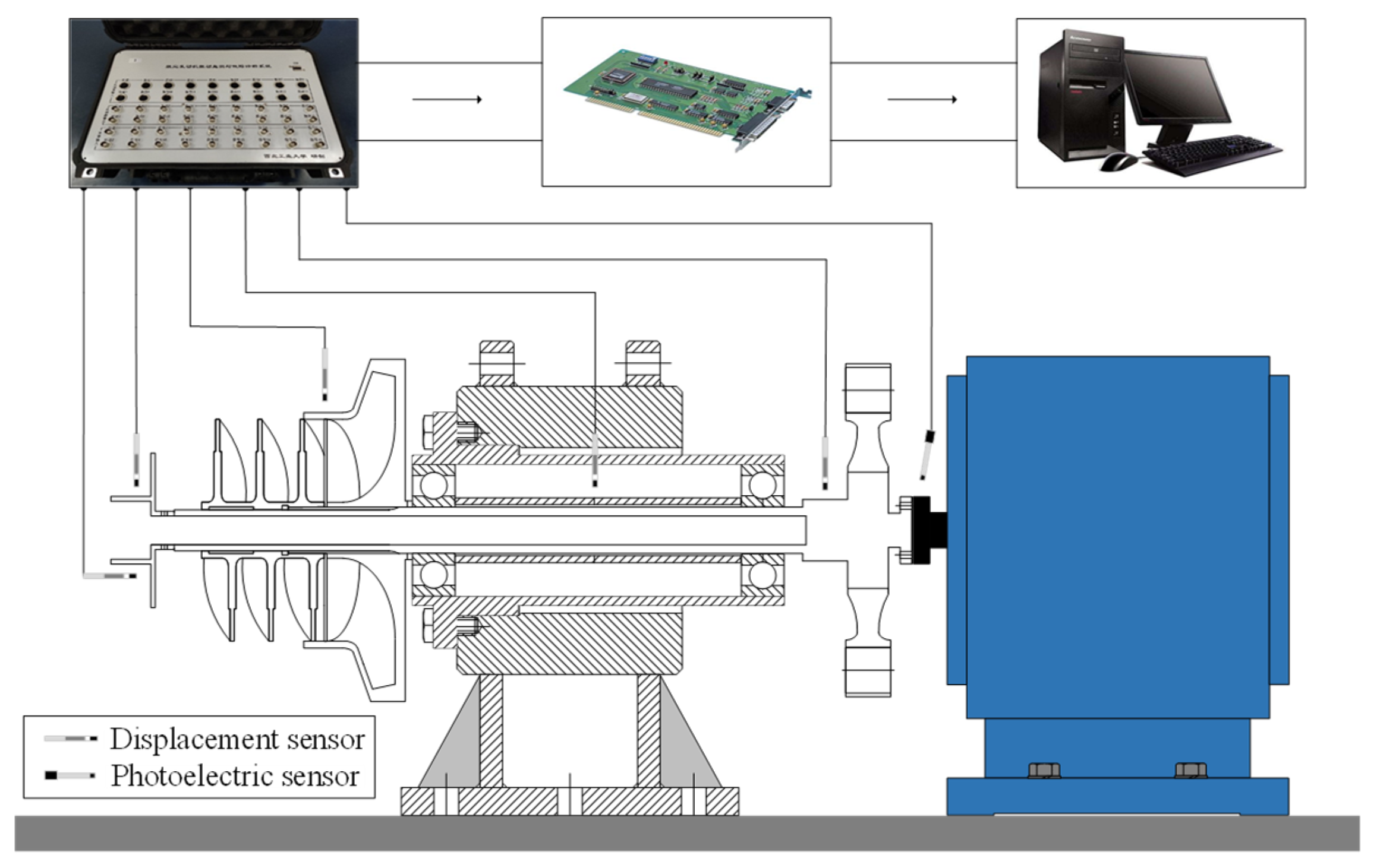
4.1. Turbopump Rotor Test System

The turbopump rotor test system with angular contact ball bearings corresponds to the construction of the turbo pump in Figure 3. The rotor was flexibly connected to the drive motor, and the experimental system operates in the speed range 0 to 12,500 r/min. The reflective paper was attached to the coupling as a phase marker.
A test system was designed to obtain rotor vibration information. It consists of sensors, signal conditioner, data acquisition card and computer, as shown in Figure 10. The vibration information was captured by displacement and acceleration sensors, and the speed was monitored by photoelectric sensors. The sensors were mounted orthogonally in order to reflect the horizontal and vertical characteristics. The shaft end nut, the centrifugal wheel, the sleeve and the turbine were defined as the test sections. At the same time, the acceleration sensor was mounted on the rotor support. Thus, six measurement sections were formed in total. The sampling frequency was set at 10 kHz. The software CAMB 9100 2.0 for rotating machine condition monitoring and dynamic balancing system was used for subsequent analysis.

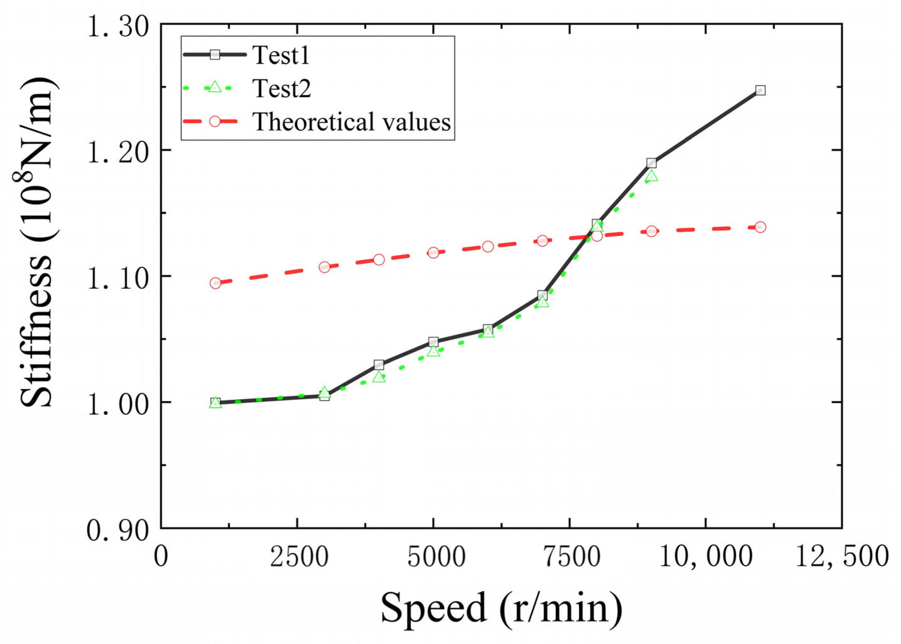
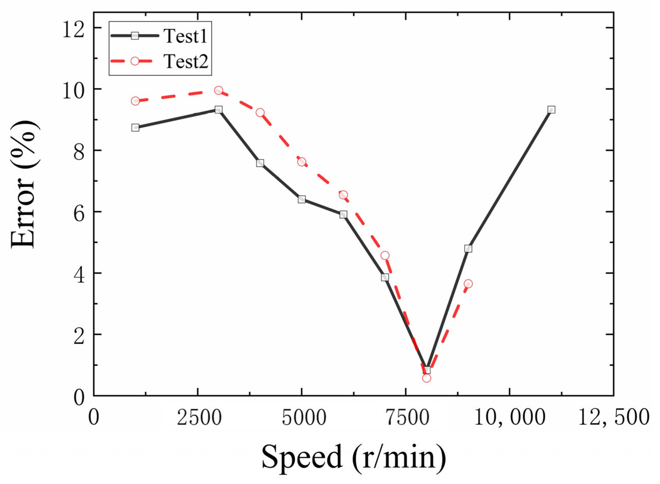
4.2. Stiffness Theoretical Model Verification

In the operating condition, the interference between the inner ring of the bearing and the spindle was 0.019 mm, and the clearance between the outer ring of the bearing and the housing was 0.021 mm. The tightening torque of the locking nut was 1400 Nm. The contact angle of the bearing was determined to be 8.37°. It is used as an iterative initial value, and the bearing stiffness was determined according to the stiffness theoretical model. The effect of speed on stiffness was also analyzed. The bearing parameters required in this calculation are shown in Table 3.
Figure 11 illustrates the theoretical values of the bearing stiffness. It can be seen that the bearing stiffness gradually increases from 1.08 × 10⁸ N/m to 1.14 × 10⁸ N/m as the speed increases. This indicates that the stiffness shows a significant trend with speed. This reflects the dynamic change in the rotor bearing stiffness of the turbopump. At the same time, as the speed increases, the rate of change in the bearing stiffness converges to a stable value.
As the stiffness of angular contact ball bearings cannot be measured directly, a stiffness identification method was introduced using the linear relationship between response and unbalance [12]. During the test, the rotor system without added unbalance was carried out. The unbalance response was recorded. Then, an unbalance was added to the centrifugal wheel (Table 4). The vibration response was recorded.
Figure 12 illustrates the unbalanced response of the turbopump rotor in Test 1. The speed was gradually increased to 11,500 r/min, followed by a deceleration and stop. It can be seen that the sensitivity of the rotor components to unbalance varies with the addition of unbalance at the centrifugal wheel. The response amplitude was greatest at the shaft end, followed by the centrifugal wheel, and lowest at the sleeve. This is consistent with the shaft end being in the cantilever section, where the vibration response was greater. As the turbopump was a rigid rotor, the critical speed was higher than the operating range. Therefore, with the exception of the centrifugal wheel, the variation in vibration displacement with speed was not significant. However, the vibration acceleration of the rotor support rises rapidly with increasing speed. The vibration threshold was approached at 11,500 r/min, which will affect the operating conditions.
Meanwhile, Figure 13 shows the unbalance response of the turbopump rotor in Test 2. The effect of location on the unbalance is consistent. The response amplitude was highest at the shaft end, followed by the centrifugal wheel, and the sleeve has the smallest. At the same time, the response was significantly higher than Test 1, when the amount of unbalance increases.
The rotor response was found to be very sensitive to the amount of unbalance. As shown in Figure 14, the unbalance response at the turbine was stable below 2000 r/min. As the speed increased, the unbalance response increased rapidly. In order to further investigate the influence mechanism, the vibration response obtained in Test 1 and Test 2 was subtracted from the initial state vector without adding the unbalance; this eliminates the influence of the initial unbalance. Hence, the bearing stiffness was obtained using the identification method in this work.
As shown in Figure 15, the turbopump bearing identification stiffness exhibits a dynamic change. As the speed increases, the stiffness gradually increases from 1.00 × 10⁸ N/m to 1.25 × 10⁸ N/m. This indicates that the increase in centrifugal force caused by the speed will lead to changes in the bearing structural dimensions. This in turn affects internal parameters such as clearance and contact angle; ultimately, the bearing stiffness was varied. It is worth noting that the identification value of the stiffness shows a convergence trend as the speed increases. In order to compare the theoretical model of bearing stiffness, the theoretical values of stiffness are also shown in Figure 15. The results show that the experimental identification results were closely related to the operating conditions, and that meets the theoretical expectations.
In order to compare the difference between the theoretical model and the identification results, the stiffness estimation error of the angular contact bearing was calculated as shown in Figure 16. The evolution law of the two test results was consistent. At the same time, it can be seen that the estimated error of the angular contact bearing stiffness was within 10%. Through the test verification, the validity of the turbopump bearing stiffness model was demonstrated. It will provide important support for the design of the turbopump.

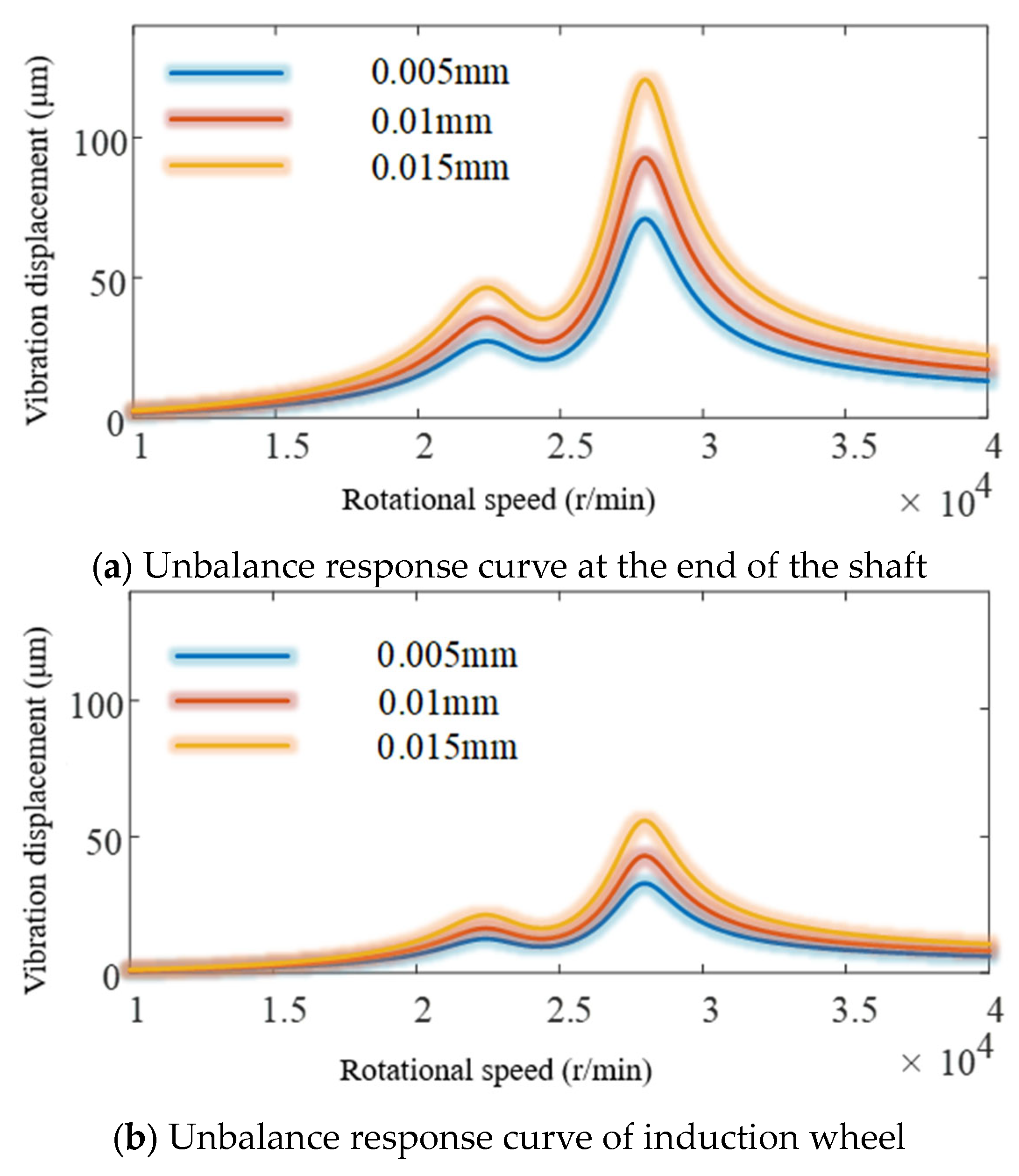
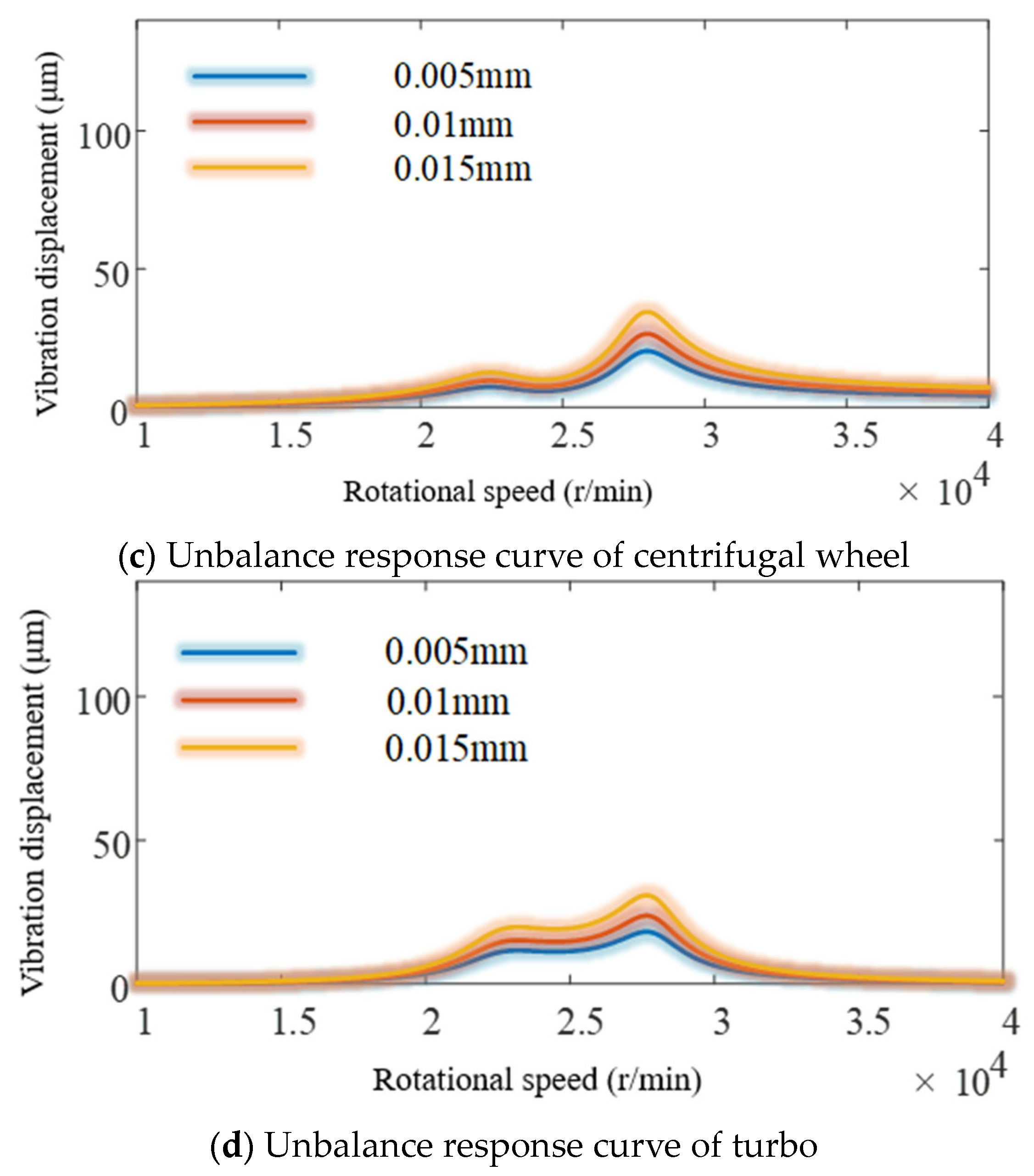
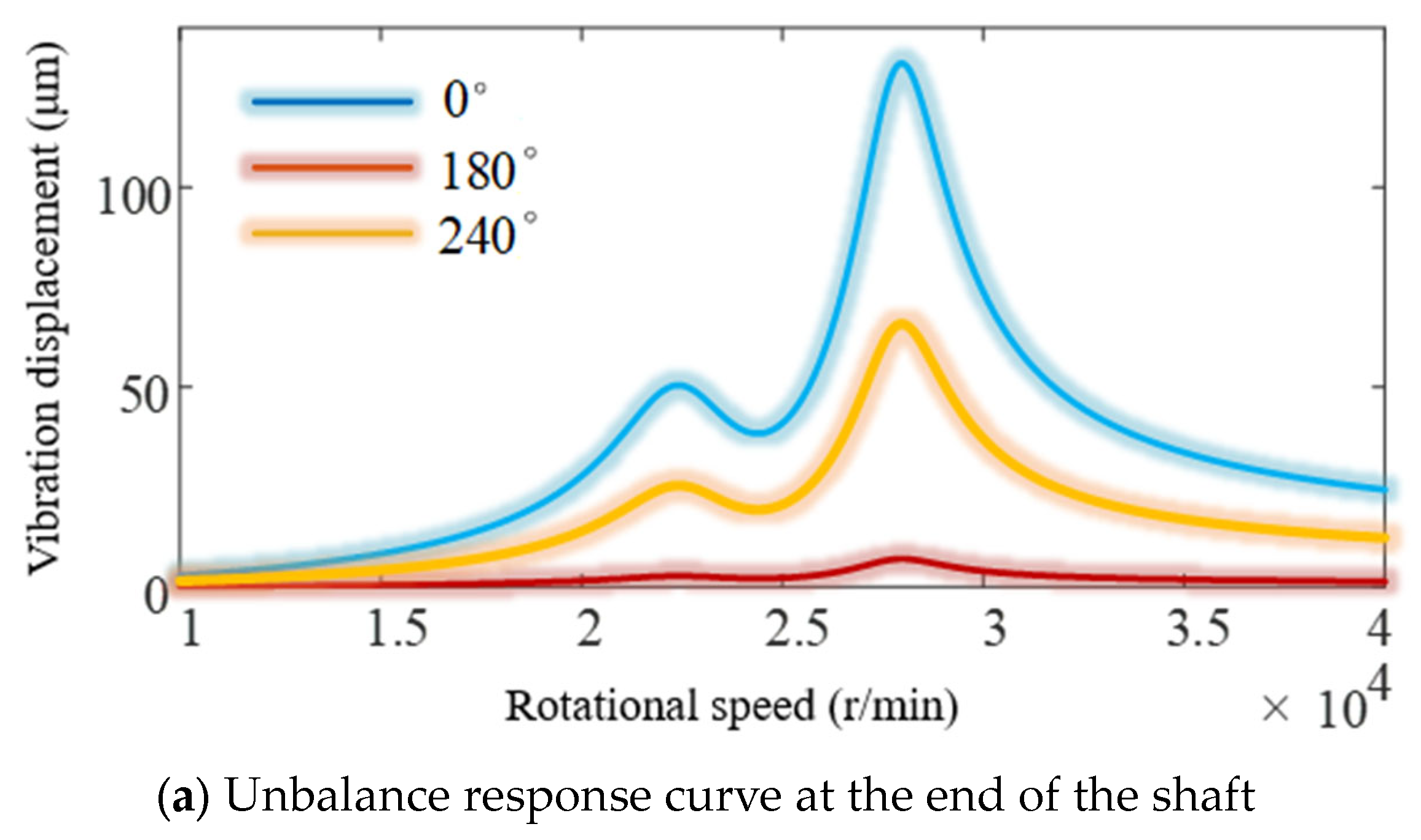
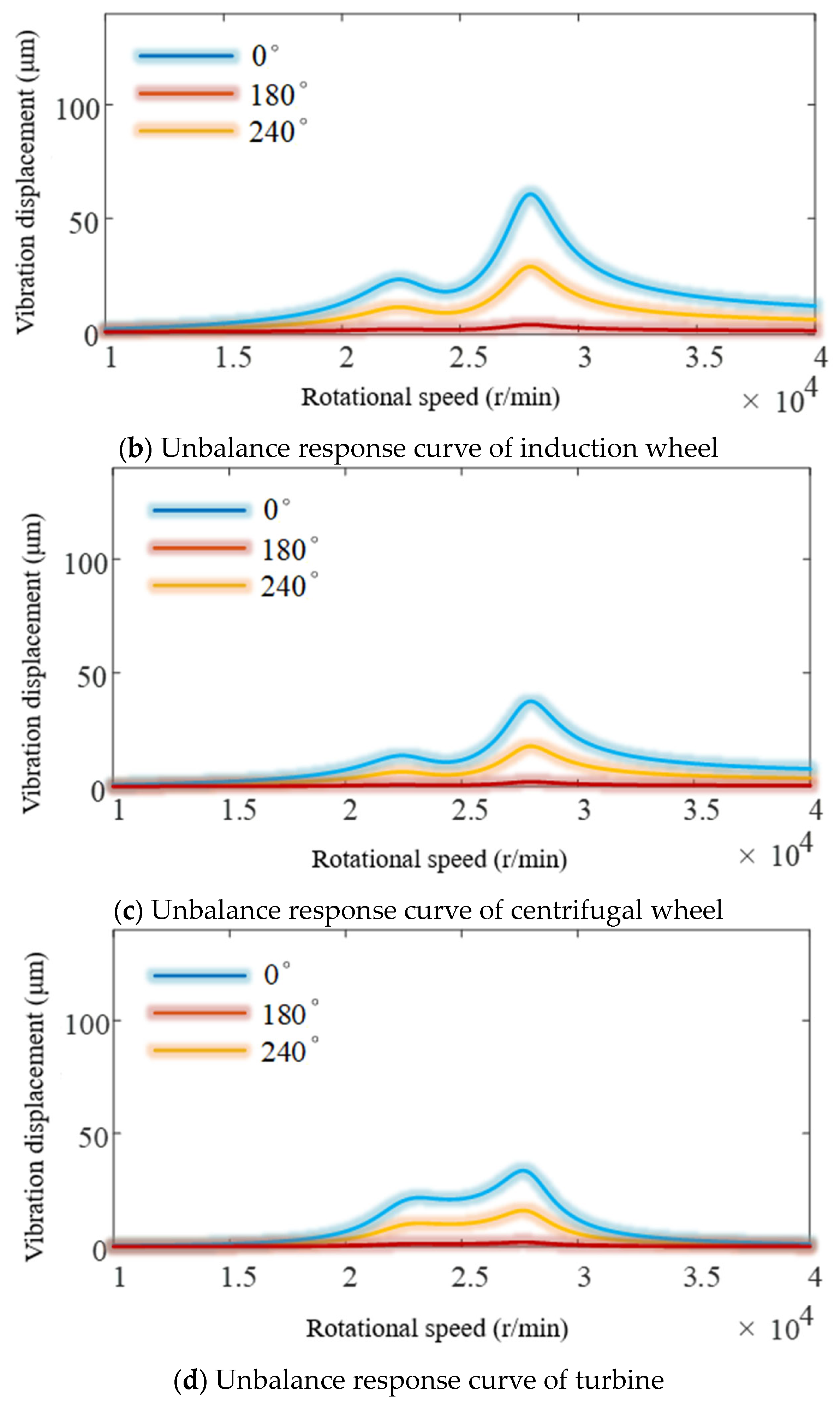
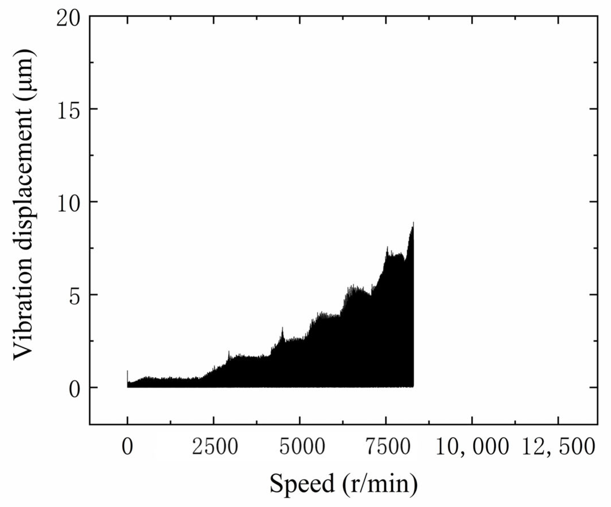
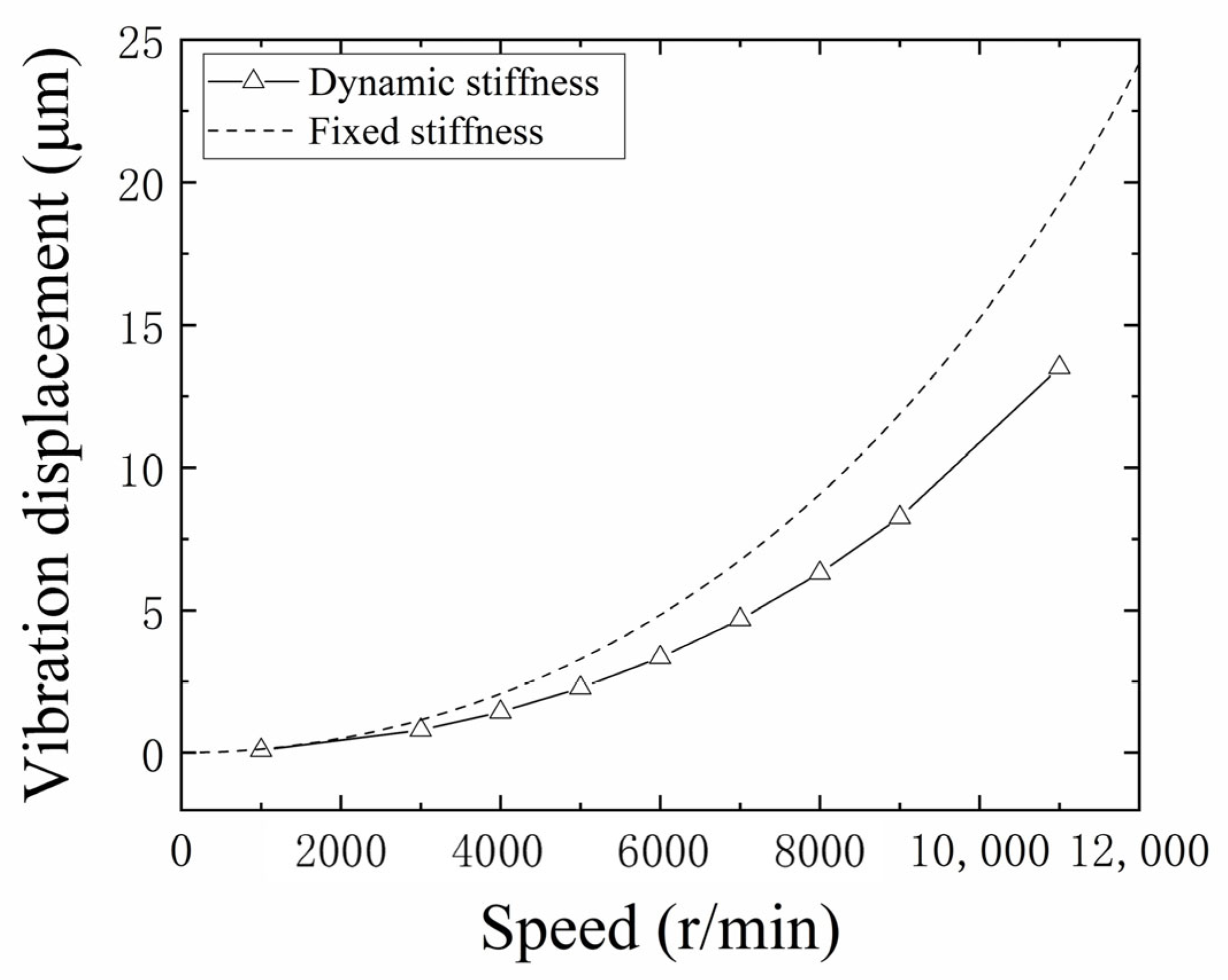
4.3. The Influence of Stiffness on Unbalance Response

As discussed in Section 2.2, axial force is an important factor affecting stiffness. So, tests were carried out at an axial load of 1850 N. As shown in Figure 17, the unbalance response of the turbine occurs in a similar law to that of the unapplied axial force (Figure 14). The unbalance response of the rotor is stable up to 2000 r/min. As the speed continued to increase, the unbalance response at the turbine increased. However, as the axial force increases, the magnitude of the unbalance response decreases significantly at the same speed.
The unbalanced response of turbopump rotors is an important factor affecting their performance in service. Through the work above, the phenomenon of dynamic changes in the stiffness characteristics has been identified. The evolution law and mechanism of the dynamic stiffness have also been revealed. In order to investigate the influence of the bearing stiffness of the turbopump on the unbalanced response, the following work has been carried out.
Firstly, the dynamics model of the rotor system was used to determine the unbalance response by considering the bearing stiffness as both a fixed value and a dynamic variation, respectively. The dynamic stiffness was determined by experimental data. Using the unbalanced response at the shaft end, the effect of the dynamic characteristics of the stiffness was explored, as shown in Figure 18.
It can be seen that the unbalanced response of the turbopump was significantly lower in the dynamic stiffness state compared to the fixed stiffness value. This is in better agreement with the actual test results. Therefore, the stiffness model should be modified in the actual turbopump rotor design. The accuracy of the damping can be improved by using the dynamic stiffness model.

5. Conclusions

In this paper, the dynamics of a rocket turbopump rotor with angular contact ball bearings were investigated. The focus is on the effect of bearings stiffness on the dynamic behavior of turbopump rotors. Theoretical analysis and experimental verification were carried out. The following conclusions are obtained:
(1)
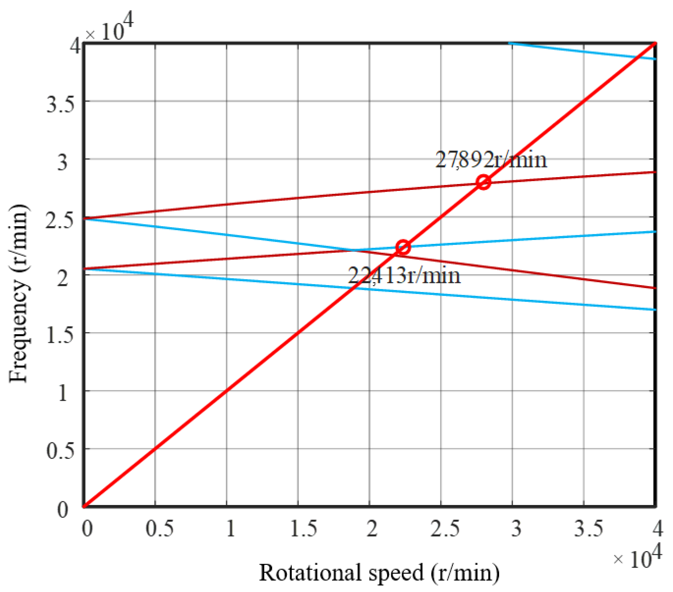
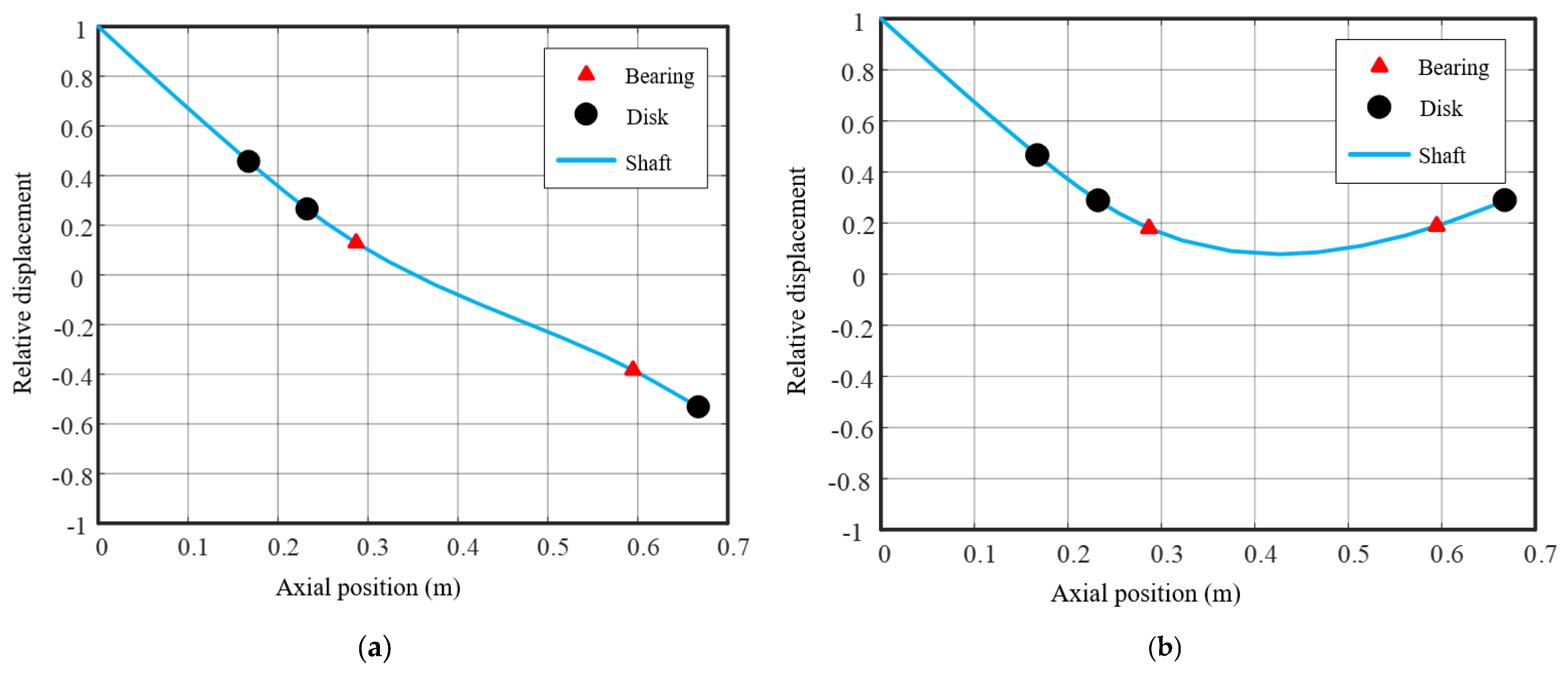
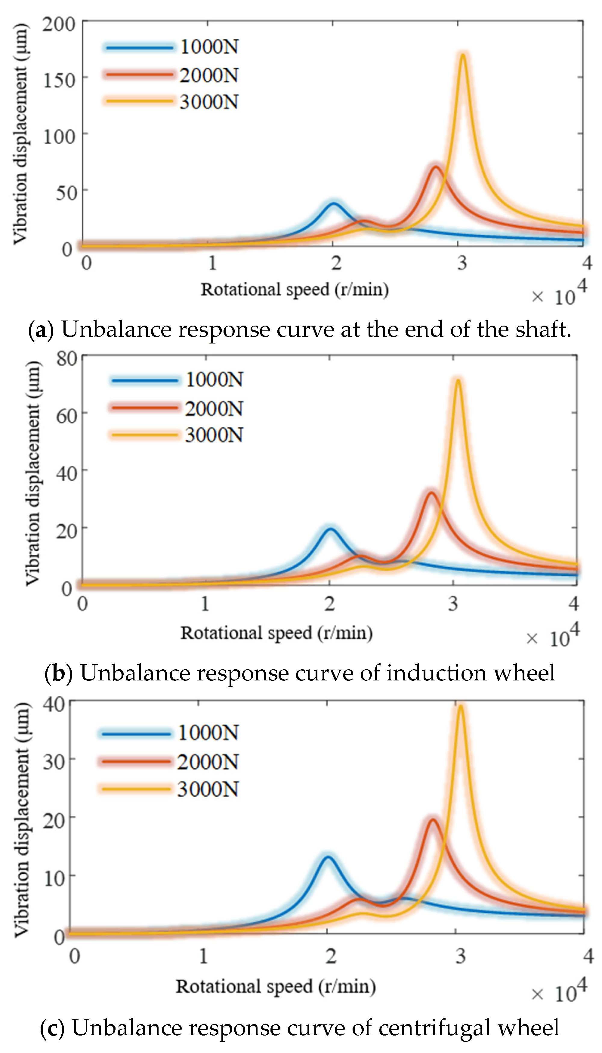
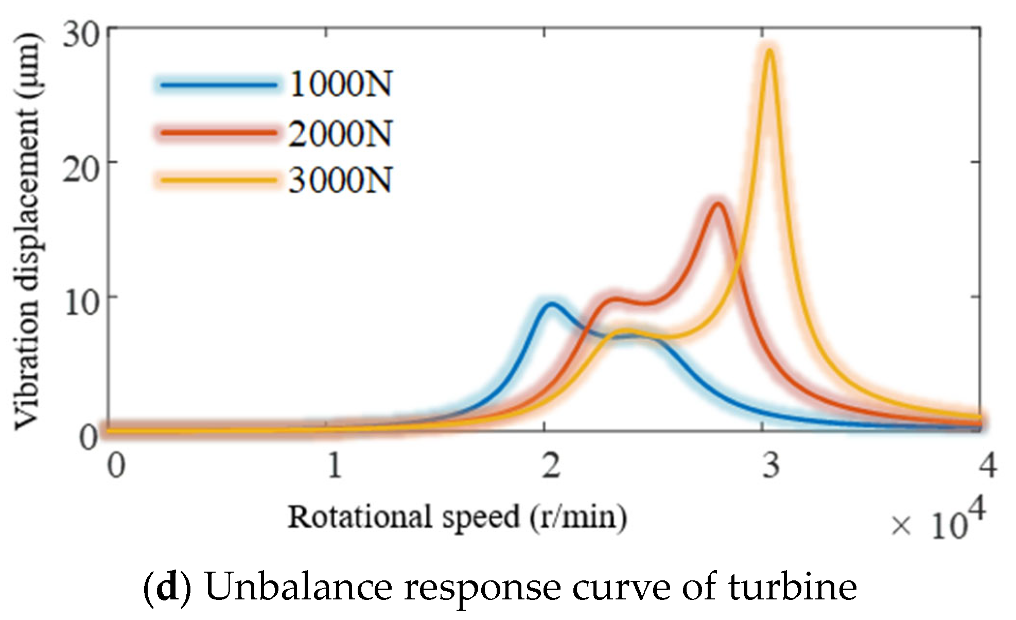
A theoretical model for the angular contact ball bearings stiffness considering speed, structure and assembly parameters was developed. Then, a dynamic model of the rotor system was also developed. The dynamics of the turbopump rotor system were also calculated. The effects of component position, fit state and axial force on the unbalance response were elucidated. It was found that the shaft end was more sensitive to the unbalance response. It was shown that the unbalance response was an important factor affecting the service performance.
(2)
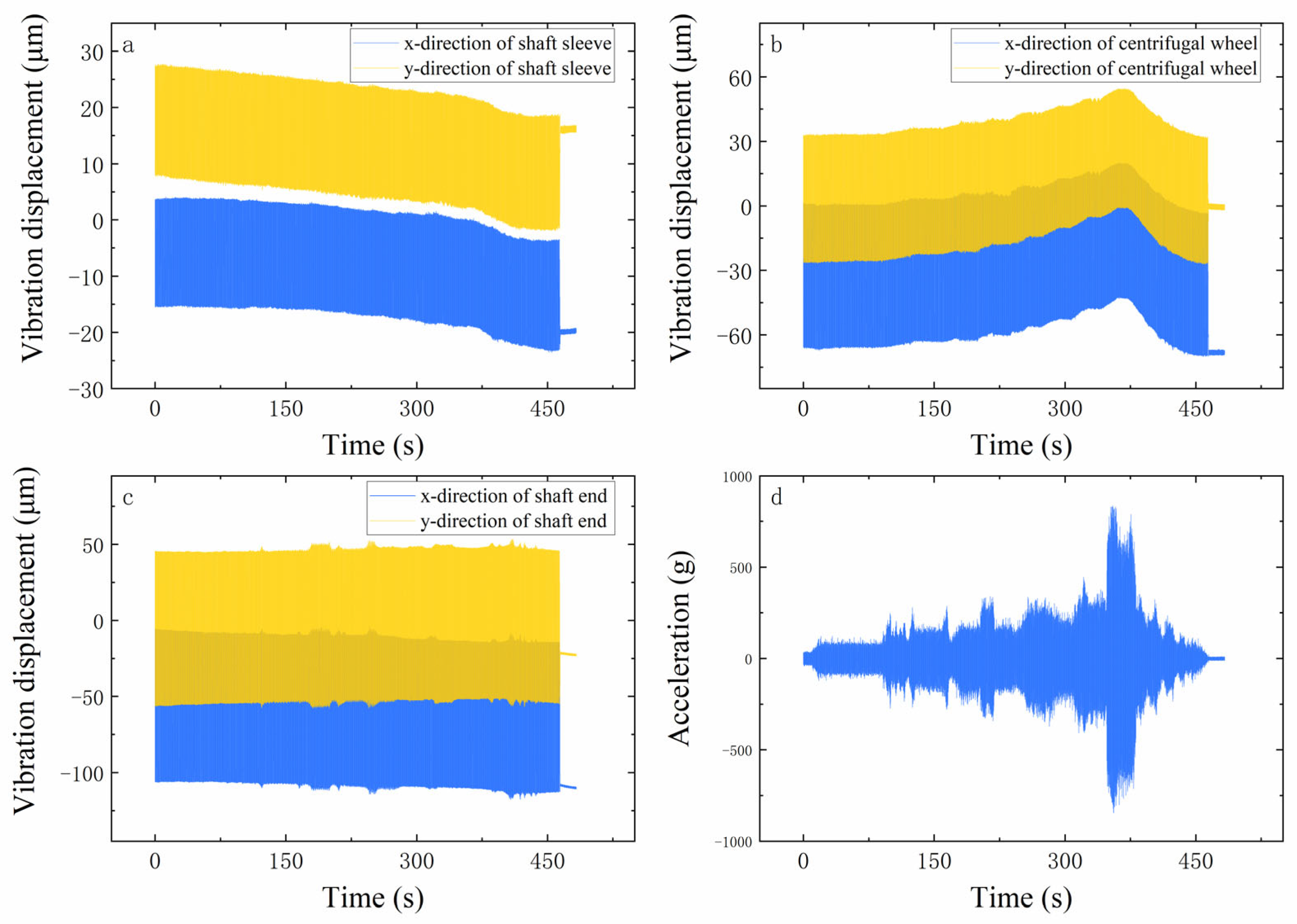
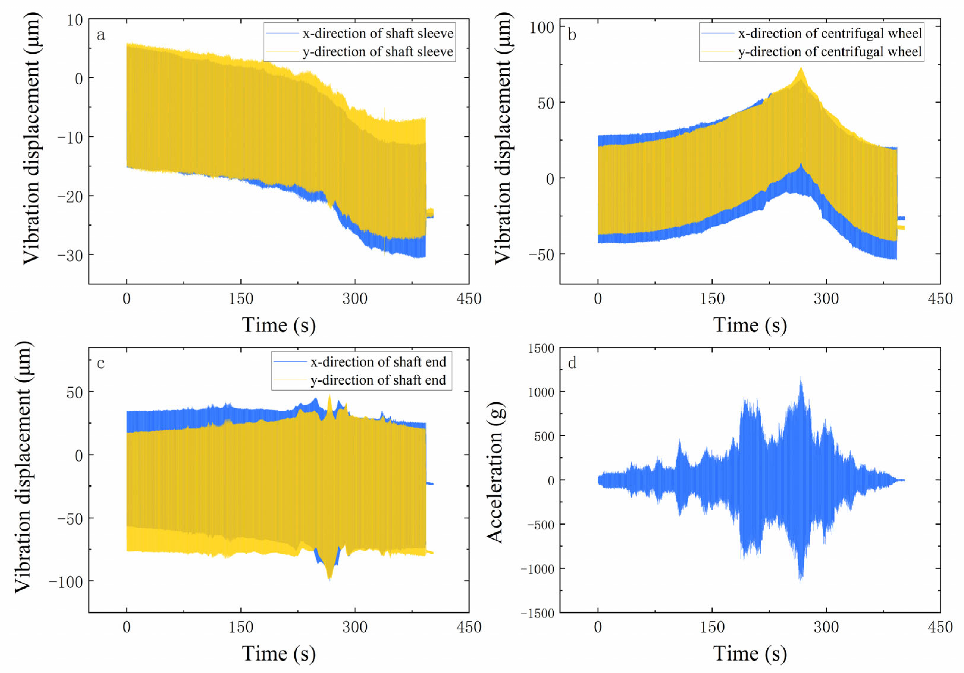
In order to verify the accuracy of the stiffness model and the dynamics model, a turbopump rotor test system with angular contact ball bearings was designed. Unbalance response tests were also carried out. The tests found that the dynamic characteristics were consistent with the theoretical analysis, while the axial force reduced the unbalanced response of the rotor. It was shown that the developed model of the stiffness is accurate with the dynamics of the rotor system. This provides support for the dynamics design of a turbopump with angular contact ball bearings.
(3)
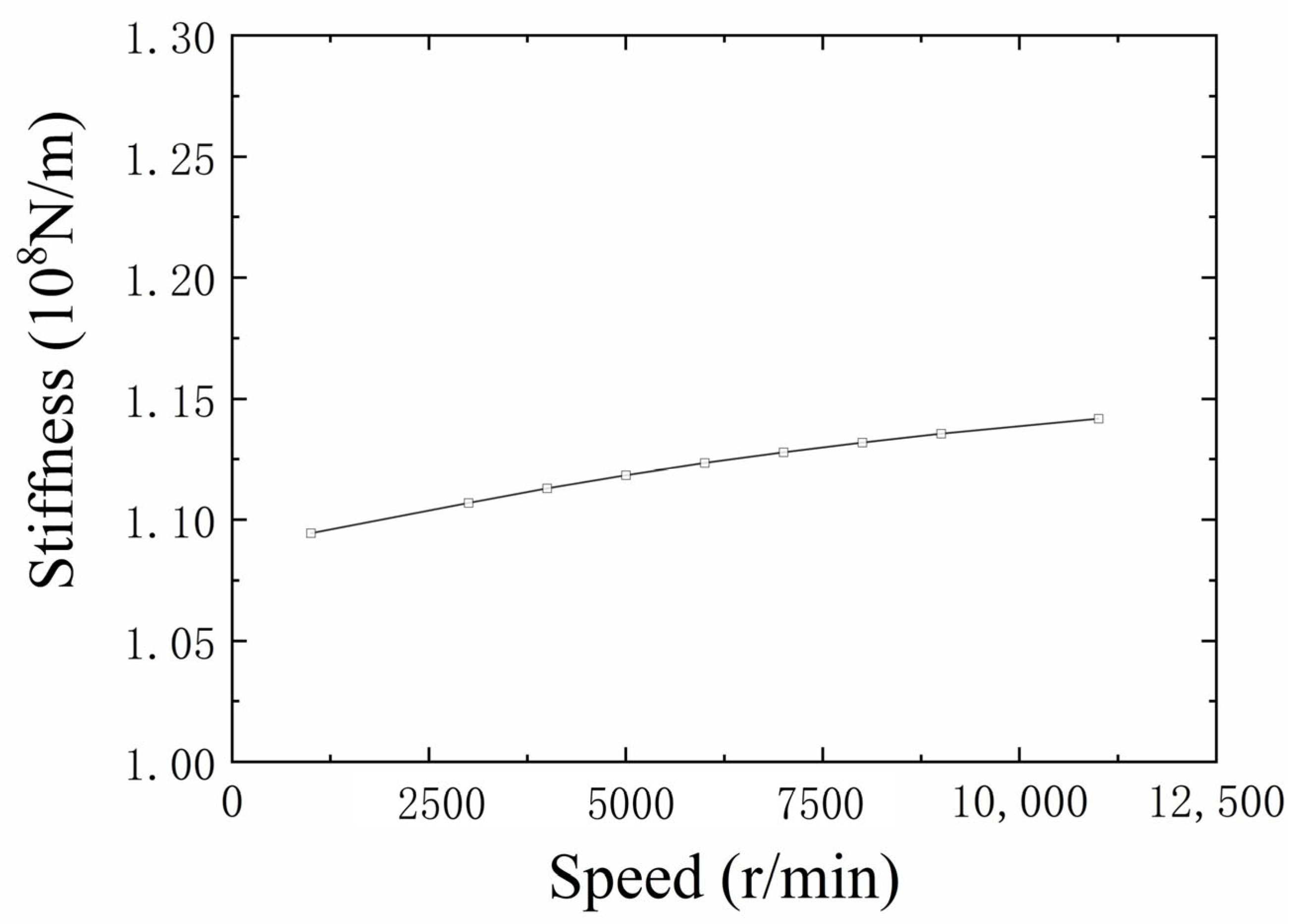
As the stiffness of angular contact ball bearings cannot be measured directly, a stiffness discrimination model was introduced. The dynamic increase in the bearing stiffness was found in the test. The variation law and mechanism of the stiffness were revealed. It was verified that the stiffness prediction error was less than 10%. This provides important support for the design of turbopump rotors.
(4)
The unbalanced response of the turbopump rotor at dynamic stiffness was significantly lower compared to the fixed values. This is in better agreement with the actual test results. So, the effect of dynamic stiffness on the dynamic response of the turbopump was elucidated.
Therefore, the stiffness model should be modified in the turbopump rotor design. The accuracy of the dynamical design can be improved using a dynamic stiffness model. This provides the theoretical basis for the development of a new generation of highly reliable, high-power, reusable turbopumps.

Author Contributions

Study concept and design: Y.S. Acquisition of data: K.X. Analysis and interpretation of data: Y.S. and K.X. Drafting of the manuscript: Y.S. and Y.G. Critical revision of the manuscript for important intellectual content: K.X. Statistical analysis: L.J. All authors have read and agreed to the published version of the manuscript.

Funding

This work is financially supported by Fundamental Research Funds for the Central Universities (Grant No. D5000210486) and National Major Science and Technology Projects of China (Grant No. 2017-IV-0001-0038).

Data Availability Statement

Not applicable.

Conflicts of Interest

The authors declare that they have no known competing financial interests or personal relationships that could have appeared to influence the work reported in this paper.

Abbreviations

α contact angle
βjattitude angle
βeccentricity phase
εmass eccentricity
Cclearance
C damping matrix
Drolling body diameter
d inner diameter of the bearing
d 0 inner diameter of the shaft
d g The diameter of the bottom of the raceway of the inner ring
Δ d inner diameter of the bearing inner ring
Δ d g the diameter of the inner ring raceway groove bottom
Eelastic modulus
F c centrifugal force
J moment of inertia
Kstiffnesses
KStiffnesses matrix
G gyroscopic torque matrix
M g j gyroscopic moment
M mass matrix
munbalanced mass
nthe number of iteration steps
ρ material density
Rraceway curvature radius
XThe distance between the raceway and the ball center
Ocurvature center
Qcontact load of the inner and outer ring raceway
Q unbalanced force vector
ω the inner ring rotation velocity
ω m Angular velocity of ball revolution
Ω Rotor speed
fThe ratio of the radius of curvature to the rolling element diameter
Δ I ω hollow shaft mating diameter
v Poisson’s ratio
λ The distribution coefficients of the raceway friction torque
q i end stress of the inner ring
q displacement vector
δ displacement
θ angular displacement
ZNumber of balls
subscript
iinner ring
oouter ring
bbearings
sshafts
aaxial
rRadial
αAngular
jThe ball number
subscript
The location after deformation
srotor system

References

  1. Childs, D.W. The Space Shuttle Main Engine High-Pressure Fuel Turbopump Rotordynamic Instability Problem. J. Eng. Power 1978, 100, 48–57. [Google Scholar] [CrossRef]
  2. Jeon, S.M.; Kwak, H.D.; Yoon, S.H.; Kim, J. Rotordynamic analysis of a turbopump with the casing structural flexibility. J. Propuls. Power 2008, 24, 433–436. [Google Scholar] [CrossRef]
  3. Zakeralhoseini, S.; Schiffmann, J. Design, computational and experimental investigation of a small-scale turbopump for organic Rankine cycle systems. Energy Convers. Manag. 2023, 287, 117073. [Google Scholar] [CrossRef]
  4. Li, W. Research on the Fault Mechanism and Diagnosis Technology of Liquid Rocket Engine Turbopump; Beijing University of Chemical Technology: Beijing, China, 2020. [Google Scholar]
  5. Apollonio, A.; Anderlini, A.; Valentini, D.; Pace, G.; Pasini, A.; Salvetti, M.V.; d’Agostino, L. Concurrent theoretical, experimental and numerical analyses of mixed-flow turbopump design. Aerosp. Sci. Technol. 2022, 123, 107459. [Google Scholar] [CrossRef]
  6. Zhao, L.; Liao, M.; Hong, L.; Lei, X.; Li, M.; Wang, S.; Hou, L.; Shao, Z. Analysis of engine vibration response under sudden addition unbalance. J. Aerosp. Power 2022, 37, 12. [Google Scholar]
  7. Wensing, J.A. On the Dynamics of Ball Bearings; University of Twente: Enschede, The Netherlands, 1998. [Google Scholar]
  8. Du, D.; Li, B. A review of key technologies for structural dynamics design of liquid rocket motors. J. Aeronaut. 2023, 444, 27554. [Google Scholar]
  9. Yan, Z. Reliability and Dynamic Stiffness Analysis of Aero-Engine Bearings; Xi’an Technological University: Xi’an, China, 2017. [Google Scholar]
  10. Yin, Y. Stiffness Study of Engine Magazine Structure with Bolted Coupling; Dalian University of Technology: Dalian, China, 2016. [Google Scholar]
  11. Li, Q. Study on the Effect of Support Stiffness on the Critical Speed of Rotor System; Shenyang Aerospace University: Shenyang, China, 2014. [Google Scholar]
  12. Jiang, Y.; Shi, B.; Zhang, T.; Chen, J.; Bai, G. Stiffness Characteristic of Co-Rotating/Counter-Rotating Inter-Shaft Bearing with Different Supporting Structures. J. Propuls. Technol. 2022, 43, 1–12. [Google Scholar]
  13. Ding, Z. Finite element analysis of dynamic stiffness of a type of aero-engine front support. J. Chang. Aeronaut. Vocat. Tech. Coll. 2014, 14, 5. [Google Scholar]
  14. Ri, C.; Namgung, H.; Zhang, Z.; Zhang, Z.; Chae, C.; Ri, K.; Ho, P.; Zhang, R. Comprehensive stiffness analysis of the cylindrical roller bearing for aircraft engines considering the radial clearance. Aircr. Eng. Aerosp. Technol. 2023, 95, 62–72. [Google Scholar] [CrossRef]
  15. Jeon, S.M.; Kwak, H.D.; Yoon, S.H.; Kim, J. Rotordynamic analysis of a high thrust liquid rocket engine fuel (Kerosene) turbopump. Aerosp. Sci. Technol. 2013, 26, 169–175. [Google Scholar] [CrossRef]
  16. Outirba, B.; Hendrick, P. Influence of geometrical parameters on the performance of brush seals for aero-engines bearing chambers. In Proceedings of the Asme Turbo Expo: Turbine Technical Conference and Exposition, Montreal, QC, Canada, 15–19 June 2015; pp. 23–27. [Google Scholar]
  17. Hong, J.; Wang, H.; Xiao, D.; Chen, P. Effects of Dnamic Stiffness of Rotor Bearing on Rotordynam in Characteristics. Aeroengine 2008, 34, 23–27. [Google Scholar]
  18. Du, J.; Li, M.; Wang, Y.; Jiang, X. Effects of Vibration of Supporting Structure on Dynamic Characteristics of a Turbopump Rotor. J. Propuls. Technol. 2023, 44, 1–12. [Google Scholar]
  19. Jiang, Y.; Liao, M.; Chen, J.; Zeng, Y.; Shi, B.; Hong, L. Support Stiffness Dependent on Aero-engine Bearing Assembly Conditions. J. Vib. Meas. Diagn. 2020, 40, 348–354+421. [Google Scholar]
  20. Lu, P.; Liao, M.; Li, M. Dynamic Stiffness Test and Its Application in Analysis of Unbalance Response of Rotors. Noise Vib. Control 2014, 34, 207–211. [Google Scholar]
  21. Qiao, L. Stiffness Characteristics Analysis and Experimental Research of the Special-Shaped Bearing for Elastic Support Structure; Dalian University of Technology: Dalian, China, 2018. [Google Scholar]
  22. Zhao, W. Research on the Whole Engine Vibration Modeling and Validation of Aero-Engine Considering the Dynamic Stiffness of the Tested Casing Bearing; Nanjing University of Aeronautics and Astronautics: Nanjing, China, 2012. [Google Scholar]
  23. Junzo, O. Design and Calculation of Ball Bearing; China Machine Press: Beijing, China, 2003. [Google Scholar]
  24. Bu, C.; Xia, B.; Lian, Y.; Zeng, H. Simulation of hertz transient contact/impact of flexible bodies. J. Earth Sci. 2012, 23, 225–232. [Google Scholar] [CrossRef]
  25. Harris, T.A.; Kotzalas, M.N. Rolling Bearing Analysis-2 Volume Set; CRC Press: Boca Raton, FL, USA, 2006. [Google Scholar]
  26. Liao, M. Aero-Engine Rotor Dynamics; Xi’an Northwestern Polytechnical University Press: Xi’an, China, 2006. [Google Scholar]
  27. Rao, J.S. Rotor Dynamics; New Age International: Daryaganj, India, 1996. [Google Scholar]
Figure 1. The relative position of the ball bearing.
Vibration 06 00041 g001
Figure 2. Schematic diagram of: (a) position, (b) displacement and (c) load of the jth ball under loading.
Vibration 06 00041 g002
Figure 3. Schematic diagram of the turbo pump rotor.
Vibration 06 00041 g003
Figure 4. Discrete model of rotor system.
Vibration 06 00041 g004
Figure 5. Campbell diagram of turbopump rotor system.
Vibration 06 00041 g005
Figure 6. (a) 1st order mode, (b) 2nd order mode for turbo pump.
Vibration 06 00041 g006
Figure 7. Response of turbopump rotor under different axial forces.
Vibration 06 00041 g007aVibration 06 00041 g007b
Figure 8. Response of turbopump rotor at different mating clearances.
Vibration 06 00041 g008aVibration 06 00041 g008b
Figure 9. Response of the turbopump rotor at the initial position deflection angle.
Vibration 06 00041 g009aVibration 06 00041 g009b
Figure 10. Schematic diagram of rotor test system.
Vibration 06 00041 g010
Figure 11. The variation in stiffness with speed.
Vibration 06 00041 g011
Figure 12. Unbalance response of the turbopump rotor in Test 1: (a) hub center, (b) centrifugal wheel, (c) shaft end and (d) bearing support.
Vibration 06 00041 g012
Figure 13. Unbalance response of the turbopump rotor in Test 2: (a) hub center, (b) centrifugal wheel, (c) shaft end and (d) bearing support.
Vibration 06 00041 g013
Figure 14. Unbalance response of the turbine in Test 1.
Vibration 06 00041 g014
Figure 15. Comparison of experimental and theoretical stiffness of the ball bearing.
Vibration 06 00041 g015
Figure 16. Stiffness error of deep groove ball bearing.
Vibration 06 00041 g016
Figure 17. Unbalance response of turbine under axial force of 1850 N.
Vibration 06 00041 g017
Figure 18. Influence of dynamic stiffness on shaft end unbalance response.
Vibration 06 00041 g018
Table 1. Parameters of disk element.
ProjectInducer WheelCentrifugal WheelTurbine
Radial moment of inertia/kg·m20.0068420.027310.03904
Polar moment of inertia/kg·m20.008990.050270.07707
Quality/kg3.0256.9788.86
Node number71027
Table 2. Distribution of the unbalance.
PositionMeasure of Inequality (g·cm)
QualityPhase
Inducer wheel12.40
Centrifugal wheel7.40
Turbine7.40
Table 3. Parameters of bearing element.
Density g/cm3Modulus of Elasticity GPaPoisson’s RatioNumber of BallsInside Diameter mmOutside Diameter mmBall Diametermm
7.752000.29107012517.46
Table 4. Unbalance magnitude and phase.
GroupAmplitude/g·mmPhase/°
Test 143.36560
Test 2270.81240
Disclaimer/Publisher’s Note: The statements, opinions and data contained in all publications are solely those of the individual author(s) and contributor(s) and not of MDPI and/or the editor(s). MDPI and/or the editor(s) disclaim responsibility for any injury to people or property resulting from any ideas, methods, instructions or products referred to in the content.

