Article

Design and Stability Analysis of a Robust-Adaptive Sliding Mode Control Applied on a Robot Arm with Flexible Links

Department of Mechanical Engineering, Faculty of Engineering and Architecture, İzmir Katip Çelebi University, İzmir 35620, Turkey
Vibration 2022, 5(1), 1-19; https://doi.org/10.3390/vibration5010001
Submission received: 22 October 2021 / Revised: 25 December 2021 / Accepted: 28 December 2021 / Published: 30 December 2021
(This article belongs to the Topic Dynamical Systems: Theory and Applications)

Abstract

:
Modelling errors and robust stabilization/tracking problems under parameter and model uncertainties complicate the control of the flexible underactuated systems. Chattering-free sliding-mode-based input-output control law realizes robustness against the structured and unstructured uncertainties in the system dynamics and avoids the excitation of unmodeled dynamics. The main purpose of this paper was to propose a robust adaptive solution for stabilizing and tracking direct-drive (DD) flexible robot arms under parameter and model uncertainties, as well as external disturbances. A lightweight robot arm subject to external and internal dynamic effects was taken into consideration. The challenges were compensating actuator dynamics with the inverter switching effects and torque ripples, stabilizing the zero dynamics under parameter/model uncertainties and disturbances while precisely tracking the predefined reference position. The precise control of this kind of system demands an accurate system model and knowledge of all sources that excite unmodeled dynamics. For this purpose, equations of motion for a flexible robot arm were derived and formulated for the large motion via Lagrange’s method. The goals were determined to achieve high-speed, precise position control, and satisfied accuracy by compensating the unwanted torque ripple and friction that degrades performance through an adaptive robust control approach. The actuator dynamics and their effect on the torque output were investigated due to the transmitted torque to the load side. The high-performance goals, precision and robustness issues, and stability concerns were satisfied by using robust-adaptive input-output linearization-based control law combining chattering-free sliding mode control (SMC) while avoiding the excitation of unmodeled dynamics. The following highlights are covered: A 2-DOF flexible robot arm considering actuator dynamics was modelled; the theoretical implication of the chattering-free sliding mode-adaptive linearizing algorithm, which ensures robust stabilization and precise tracking control, was designed based on the full system model including actuator dynamics with computer simulations. Stability analysis of the zero dynamics originated from the Lyapunov theorem was performed. The conceptual design necessity of nonlinear observers for the estimation of immeasurable variables and parameters required for the control algorithms was emphasized.

1. Introduction

The fast stabilization and precise tracking of systems (underactuated) are regarded as a hard control issue, whose solution will address implementation from space robotics and weapon platforms to the control of air/sea/ground vehicles and systems exposed to unpredictable actuators failure [1,2,3]. The control of underactuated systems presents challenges even in the nonappearance in terms of uncertainty; however, modelling errors and disturbances add to the complications due to the active and passive degrees of freedom (DOFs) coupling [4,5].
Many favorable results have been presented, addressing robust stabilization and robust tracking control problems for classes of underactuated systems offering nonlinear control designs dealing with uncertainties. It is important to define and address robust stabilization/tracking issues for classes of underactuated systems. The underactuated systems with parametric uncertainties are driven through a set of structured nonlinear equations of motion (EOM) that can be exploited for the construction of Lyapunov functions to be used in the robustness analysis [6,7,8,9,10].
The flexible robotic arms constitute an underactuated system due to the structural flexibilities, leading to a system with higher DOFs than the total number of actuators. The DD flexible robot arm system model inherently covers significant flexibility modes, Coriolis, centripetal and gravitational effects, as well as dynamics of the actuator [11,12]. Its complex dynamic structure arises from the interaction of structural flexibilities and actuator dynamics. The high-performance goals require using high torque, lightweight direct drive systems (DDS), which involve the direct coupling of motors with their loads, due to the removal of transmission mechanisms, such as gearboxes, belts, harmonic drives, and so on. The elimination of joint elasticity, and backlash and friction, as a result, gives rise to a system with a higher servo stiffness and improved stabilization characteristics over systems that include gears. The DD structure also allows the actuator to position the shaft more precisely in comparison to a geared system. With typical gearing, the backlash contributes to a “dead zone”, which falls in the region of the system null point and reduces positional accuracy. In a DDS, however, the positional accuracy is, in practice, limited only by the error-detecting transducer system. These characteristics are the major reasons why DD actuation should be preferred over-geared systems for high-performance positioning systems. Jaritz and Spong [13] presented the results of a systematic comparison of passivity-based robust control algorithms for a 2 DOF, DD robot arm. Reyes and Kelly [14,15] presented an experimental evaluation of model-based control algorithms on a direct-drive robotic arm. The above studies on DD robotics consider the manipulator dynamics only and assume a perfectly linear variation of the generated torque with the control input, neglecting the effects of non-uniform torque. However, an important problem with DD actuators is the non-uniform distribution of the motor windings, the saliencies in the rotor/stator, and their interaction with the winding currents, which give rise to undesirable torque pulsations, named as “torque ripple” and “cogging torque” in the literature, depending on their source. What creates a problem is that with a DD system, these pulsations are directly reflected on the load side, leading to speed oscillations, which cause deterioration in the system performance. The problems related to torque pulsations or torque ripple range from small influence on accuracy to total instability. Statically, torque ripple can be thought of as load torque that varies with the rotor position, thus causing position/tracking error. Dynamically, due to its richness in high frequency, it may also excite the unmodeled dynamics of the system, giving rise to instability. Therefore, in the modelling and control of DD systems, actuator dynamic effects should be taken into account as well as the manipulator dynamics, especially when high-performance goals are involved.
The problem of modelling error originated from parameter and model uncertainties, which are solved through a precise control action that demands very accurate system models and considers all sources that excite unmodeled dynamics. Also, the consideration of actuator dynamic effect and torque pulsations is critical for high precision demands in DD robotics [16,17]. A detailed inspection of the existing literature reveals that research on underactuated DD robotic systems focused on the flexible robot manipulator control could be divided into two main groups; the first one [18,19,20] covers the research on the high-performance control of DD actuators taking only actuator dynamics into account and dealing with torque pulsation effects, the second one [21,22,23] is related to the control of underactuated robot arms, either with the consideration of passive joints or flexible links, e.g., single-link flexible arm concentrating on the stabilization and tracking of the performance of the active and passive DOFs. The utilization of high torque is required in the lightweight DD systems that involve the direct coupling of motors with their loads, due to the removal of transmission mechanisms, such as gearboxes, belts, harmonic drives etc. The joint elasticity, backlash, and friction attenuation, as a result, lead to a system having higher servo hardness and improved stabilization characteristics over systems that include gears. This structure also provides the actuator to position the shaft more precisely as compared to a geared system. The backlash that occurred in the typical gearing contributes to a “dead zone” falling in the region of the system null point and reducing the accuracy in the position [24,25,26,27]. Uecker et al. [28] demonstrate that methods based on the model achieve two to four times better performance than the Proportional-Integral-Derivative (PID); Ayten and Dumlu [29] address the tracking control of a 2 DOF DD arm with adaptive and robust control schemes; Azizi and Yazdizadeh [30] present a systematic comparison of passivity-driven robust solution for a 2 DOF DD robot arm; Santibanez et al. [31] demonstrates the effect of static friction on the set-point control of a DD system. An important problem with DD actuators is the non-uniform distribution of the motor windings, the saliencies in the rotor/stator, and their interaction with the winding currents giving rise to undesirable torque pulsations. In the literature, they are classified as torque ripple [32] and cogging torque [33] depending on their source. These pulsations are directly reflected on the load side, leading to speed oscillations, which cause deterioration in the system performance. Torque pulsations cause inaccuracies or instabilities. Statically, torque ripples can be accepted as load torque varying via rotor angular position. From the dynamic perspective, it can stimulate the unmodeled dynamics, which lead to an unstable mode [34,35]. Therefore, in the modelling and control of DD systems, the actuator dynamic is combined with the manipulator dynamics, especially when high-performance goals are involved. The high-performance goals require using high torque, lightweight DD systems, which involve the direct coupling of motors with their loads, due to the removal of transmission mechanisms, such as gearboxes, belts, harmonic drives, and so on. In the literature, techniques dealing with torque ripple elimination for DD actuators have been proposed [36,37]. Some techniques focus on the design of electric motors to achieve the production of smooth torque. Although effective for torque ripple minimization, the proposed methods are specific to the machine involved and do not offer a flexible solution. Other techniques cover the minimization of torque ripple, thereby taking a more flexible and less costly approach to the solution of the problem. Harmonic cancellation is applied through predefined current waveforms [38]. This method necessitates the torque ripple information of the motor and utilizes the model of the torque production to evaluate current waveforms injected for attenuating the unwanted torque components. These methods have parameter variation sensitivity, and their effectiveness lowers if the conditions change. As a solution to the problem of parameter and load uncertainty, Fei et al. [33,39] used parameterization techniques to cancel torque pulsations and unknown load effects for precise control. Almakhles integrated the integral and backstepping SMCs in a double-loop to ensure the position tracking capability subjected to the disturbance [40]. Petrovic et al. [38,41] presented a passivity-based adaptive control for suppressing torque ripple while enabling speed control for a permanent-magnet synchronous motor (PMSM). High-speed lightweight DD systems also require structural flexibilities to be taken into account for high precision goals. The resulting system has a higher number of passive DOFs than active control inputs, thus, it should be viewed as an underactuated system. They demonstrate nonlinearities and nonminimum phase features, which lead to a hard control problem. Krener [42] performed a survey on the application of geometric nonlinear control. Energy-based approaches [43] for the stability and tracking control of underactuated systems were also investigated. Passivity-based methods such as backstepping [44] have led to dramatic advances in controller design, but are only applicable to certain classes of underactuated systems. Research has specifically addressed the control of flexible robot manipulators and various techniques developed and validated by simulations and/or experiments [45,46,47,48]. Park et al. [49] developed input-shaping techniques; Markus [50] applies for feedforward compensation; Mansor et al. [51] presented a time delay method; Yang et al. [52] applied nonlinear adaptive control. Euler-Bernoulli beam with a fourth-order equation is used frequently to derive the model equations of a flexible link. The rotation angle corresponding to the flexible link is the common collocated output for a trajectory tracking perspective. The performance of this output measurement is not adequate, because it supplies weak vibration control [53]. Therefore, research using non-collocated output sensing, such as the link tip position, has been initiated, although it causes zero dynamics to have a non-minimum phase. Liu and Yuan [54] proposed non-collocated outputs for the flexible link; Mattioni et al. [55] used an infinite-dimensional linear model, while Meurer et al. [56] performed a theoretical study deriving a non-collocated output; De Luca et al. [3] designed a state-feedback controller to the non-minimum phase in the nonlinear system model. Full system dynamics should be considered, and methods should be developed to compensate/reject their effects, besides those imposed by external disturbances. Accurate modelling is even more crucial for the stabilization and control of underactuated systems. Problems caused by modelling errors such as tracking error and instability are even more pronounced in those systems due to the coupling between active and passive DOFs. Thus, robust methods appear to be good solutions subject to structured and unstructured uncertainties. SMC is an effective robust control method for uncertain systems; it has also found an increased application in the underactuated system control. Among application of SMC to flexible arms, Han et al. [57] proposed an SM-based observer and controller to be utilized in single-link flexible arm; Sinha and Mishra [58] used the discontinuous approach in the control design; Hosaka and Murakami [59] designed a disturbance observer to compensate the flexible modes with high-order; Lochan et al. [60] utilized an SMC with chattering to exploit the robustness. The unwanted sides of chattering on unmodeled dynamics are known. Due to the superior robustness properties to matched uncertainties of the discontinuous high-order SMCs for the underactuated system under heavy uncertainties, interesting examples of SMCs, with or without chattering, have been developed for fully actuated and underactuated systems (mostly, flexible links). However, in those studies, chattering effects appear as a tradeoff between high robustness to uncertainties and good tracking performance [61,62]. As another approach to achieve robustness and high tracking performance under heavy uncertainties, higher-order sliding mode controllers were proposed. The investigation of efficient tuning methods for the control parameters of the HOSMC (i.e., by online genetic algorithms) is another beneficial area for research. Another issue limiting the development of high order sliding mode controllers (HOSMCs) is the difficulty in deriving the system states and their derivations [63,64]. Besides, there are several studies utilizing H∞ methods for the robot arm [15,65,66]. A polytopic gain scheduled H∞ controller combined with pole placement method was represented in [67]. An iterative H∞ filter was designed to improve upon the initial estimate for the trajectory of a nonlinear underactuated vehicle [68]. H∞-based sliding mode controller was applied to a human swing leg system in [69]. A predefined time, predefined bounded attitude tracking control scheme based on nonsingular predefined time sliding mode manifold was proposed to be applied in tracking control of the rigid spacecraft with bounded external disturbances. The control law guarantees that the attitude tracking error converges to a vicinity of the origin both satisfying the predefined bound and time [70]. The problems derived from the actuator faults, measurement errors of the attitude and angular velocity, unmeasured modal displacements, uncertainties, and external disturbances in both rigid and flexible dynamic parameters were also solved in another paper [71] using an adaptive fault-tolerant attitude tracking controller. The closed-loop stability of the system was proved through the Sequential Lyapunov Method.
This paper proposes a precise stabilization and tracking control solution that involves a robust adaptive scheme combining a continuous chattering-free SMC with adaptive feedback linearization to the flexible robot arm system, considering the actuator dynamics in addition to various dynamic effects inherent to this system. In the control design process, the aim is to reduce or eliminate the undesirable effects of the actuator dynamics on the torque ripple. With the help of the developed control method, the compensation of nonlinearities such as gravitational load, friction, and torque pulsations was achieved, and the stability of zero dynamics caused by passive DOF’s for a certain output was guaranteed, while also satisfying the desired trajectory tracking performance. The outline of this paper comprises modelling of the robot arm system dynamics, having flexible links by considering the actuator dynamics, structural flexibilities, system disturbances, as well as dynamic parameter changes, and developing a robust-adaptive linearizing control method to fulfil high-performance trajectory tracking and high-speed response. Computational efficiency, precision, speed, and accuracy requirements were ensured in the simulation of the whole system.

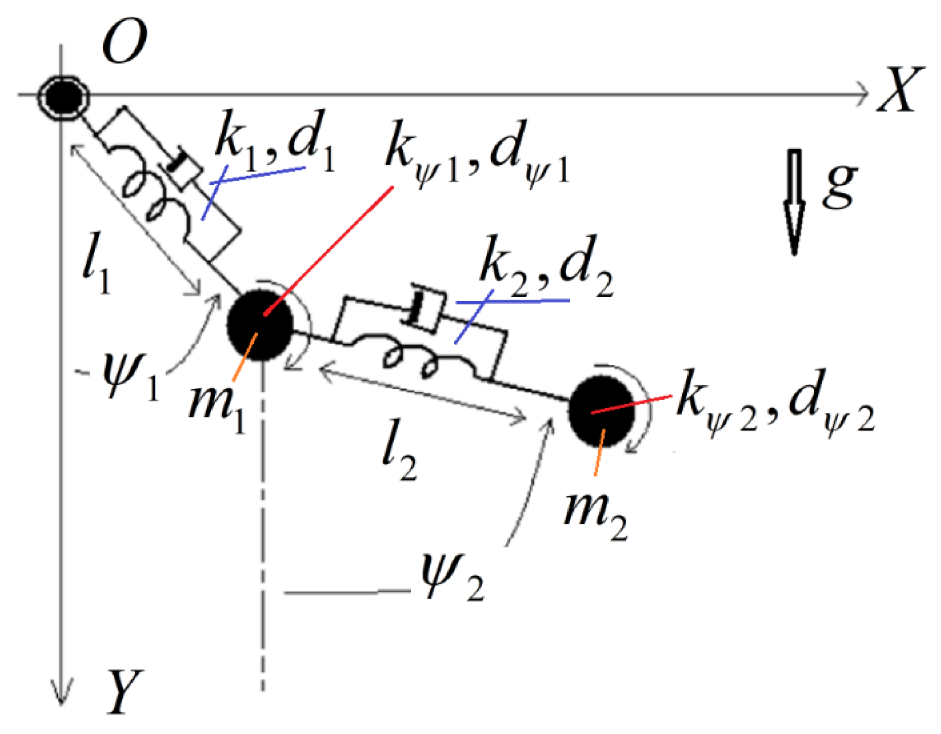
2. Mathematical Modeling of the Flexible Robot Arm

The physical model of the flexible robot arm is represented in Figure 1.
Figure 1 shows that the mechanical configurations of the robot have two flexible links and joints expressed in terms of lumped parameters. The model includes translational and rotational springs and viscous dampers. Lagrangian mechanical principles are utilized to derive the equations of motion (EOM’s) of the whole system. The generalized independent coordinates changing with time are determined as ψ 1 ( t ) , ψ 2 ( t ) , l 1 ( t ) , l 2 ( t ) . Large motion and structural variations in the dynamics of the flexible robot arm are investigated in this paper.
The kinematic constraints and velocities of the mass centres w.r.t inertial reference frame are stated as in Equations (1) and (2), respectively.
X 1 ( t ) = l 1 ( t ) sin ( ψ 1 ( t ) ) , X 2 ( t ) = l 1 ( t ) sin ( ψ 1 ( t ) ) + l 2 sin ( ψ 2 ( t ) ) Y 1 ( t ) = l 1 ( t ) cos ( ψ 1 ( t ) ) , Y 2 ( t ) = l 1 ( t ) cos ( ψ 1 ( t ) ) l 2 ( t ) cos ( ψ 2 ( t ) )
d X 1 d t = sin ( ψ 1 ) I ˙ 1 + cos ( ψ 1 ) l 1 ψ ˙ 1 d X 2 d t = sin ( ψ 1 ) l ˙ 1 + sin ( ψ 2 ) l ˙ 2 + cos ( ψ 1 ) l 1 ψ ˙ 1 + cos ( ψ 2 ) l 2 ψ ˙ 2 d Y 1 d t = sin ( ψ 1 ) l 1 ψ ˙ 1 cos ( ψ 1 ) l ˙ 1 d Y 2 d t = sin ( ψ 1 ) l 1 ψ ˙ 1 + sin ( ψ 2 ) l 2 ψ ˙ 2 cos ( ψ 1 ) l ˙ 1 cos ( ψ 2 ) l ˙ 2
The potential energy that contains the gravitational potential; translational and rotational elastic potential parts; kinetic energy that covers translational and rotational parts; and Rayleigh dissipation function, which highlights the viscous damping loss of the whole system, are defined in Equation (3), respectively.
V = m 1 g Y 1 + m 2 g Y 2 + 1 2 k 1 ( l 1 l 10 ) 2 + 1 2 k 2 ( l 2 l 20 ) 2 1 2 k 1 ( ψ 1 ψ 10 ) 2 + 1 2 k ψ 2 ( ψ 2 ψ 20 ) 2 T = 1 2 m 1 ( X ˙ 1 2 + Y ˙ 1 2 ) + 1 2 m 2 ( X ˙ 2 2 + Y ˙ 2 2 ) + 1 2 J ψ 1 ψ ˙ 1 2 + 1 2 J ψ 2 ψ 2 2 ¯ R = 1 2 d 1 I ˙ 1 2 + 1 2 d 2 I ˙ 2 2 + 1 2 d ψ 1 ψ ˙ 1 2 + 1 2 d W 2 ψ ˙ 2 2
The parameters stated in Equation (3) refer to the system parameters given in Table 1.
Four nonlinear second-order differential EOMs are obtained by writing down the Lagrangian equation that describes the dynamics of the flexible robot arm uniquely as in Equation (4), respectively.
d d t ( L ψ ˙ 1 ) L ψ 1 + R ψ ˙ 1 = Q ψ 1 , d d t ( L ψ ˙ 2 ) L ψ 2 + R ψ ˙ 2 = Q ψ 2 d d t ( L l ˙ 1 ) L l 1 + R l ˙ 1 = Q l 1 , d d t ( L I ˙ 2 ) L I 2 + R I ˙ 2 = Q l 2
where Lagrangian ( L = T V ) refers to the difference between kinetic and potential energy. Q i ’s imply that the i t h external generalized force corresponds to the generalized source (i.e., mechanical or electrical). The state equations derived from Equation (4) contain the full dynamics of the system. To define the system in state-space form, the eight-dimensional state vector is given in terms of the state variables.
These variables are the angular position, angular velocity of the joints, displacement, and its derivative of the links, i.e., x 1 = ψ 1 ,   x 2 = ψ ˙ 1 ,   x 3 = ψ 2 ,   x 4 = ψ ˙ 2 ,   x 5 = I 1 ,   x 6 = I ˙ 1 ,   x 7 = I 2 ,   x 2 = I ˙ 2 .
The state equations can be built by arranging these variables in the form given in Equation (5).
X ¯ ˙ = f ( X ¯ , u ¯ )
where X ¯ is the state vector, u   denotes external input and f ( . ) is a nonlinear function in a vector form.
The state equation in Equation (5) can be re-arranged as in Equation (6).
x ˙ 1 = x 2 , x ˙ 3 = x 4 , x ˙ 5 = x 6 , x ˙ 7 = x 8 ; ( x ˙ 2 x ˙ 4 x ˙ 6 x ˙ 8 ) = f ˆ ( x 1 , x 2 , x 3 , x 4 , x 5 , x 6 , x 7 , x 8 , u ¯ )
where f ˆ ( . ) includes nonlinear terms as state variables and external inputs.
After completing the state-space representation, the controller synthesis can be achieved.
The joints are subjected to the external torque vector u ¯ = [ u 1 u 2 0 0 ] given in Equation (7), rigidly mounted to a rotating reference frame.
u 1 , 2 = k t n 1 , 2 i q 1 , 2 + n = 1 ( K 1 , 2 c n c o s ( n p 1 , 2 θ 1 , 2 ) + K 1 , 2 s n s i n ( n p 1 , 2 θ 1 , 2 ) ) i q 1 , 2 + j = 1 ( K 1 , 2 c j μ 1 , 2 c o s ( j μ 1 , 2 θ 1 , 2 ) + K 1 , 2 s j μ 1 , 2 s i n ( j μ 1 , 2 θ 1 , 2 ) ) i q 1 , 2 + L θ 1 , 2 i d 1 , 2 i q 1 , 2
where ktn refers to the torque constant (Nm/A); Ld is direct axis stator winding inductance (H); Lq is quadrature axis stator winding inductance (H); Lθ is proportional to ( L q L d ) (H); p corresponds to the pole pair number; id and iq indicate the stator currents in terms of direct and quadrature axis components (A); n is the harmonic order (n = 1,2,…, ); K 1 , 2 c n , K 1 , 2 s n are harmonic torque components in terms of cosine and sine coefficients (Nm/A); and K 1 , 2 c j μ 1 , 2 , K 1 , 2 s j μ 1 , 2 are cogging torque components in terms of cosine and sine coefficients (Nm).
The actuator dynamics can be embedded to complete the full system dynamics with electric motor equations as follows in Equation (8),
d i q d t = R s L q i q p L d i d [ k b + n = 1 ( K c m cos n p θ + K s p sin n p θ ) ] θ · L q + 1 L q v q d i d d t = R s L d i d p L q i q + 1 L d v d v q = V m sign ( i q r i q ) | t = k T s W k = 0 , 1 , 2 , v d = V m sign ( i d r i d ) | t = k T s W k = 0 , 1 , 2 ,
where V m   is the maximum driver voltage (V), i q r and i d r are quadrature and direct axis reference current components of stator current (A), T s W   is the driver switching time constant (s), v q ,   v d are quadrature and direct axis components of the stator voltage (V), R s   is the stator phase winding resistance (Ω), k b   is the back-emf constant (V.s/rad), and K c m ,   K s p are harmonic flux components (V.s/rad).
Stator voltage components have produced an equivalent driver circuit that includes relay functions with a switching facility. The block diagram, which is utilized in the simulation of the torque input, can be represented as in Figure 2.
The generated torques in the joints are constituted by torque ripple, reluctance torque, and cogging torque, respectively (the switching of the Pulse Width Modulation (PWM) inverter operation and the torque pulsations in the output torque for the current reference are induced by the input-output control law).

3. Controller Framework: Theoretical Remarks and Implementation

The control laws were presented in the form of full state feedback. Commonly, the underactuated system control consists of designing a nonlinear observer and developing output feedback stabilization. In real conditions, most actuators are limited in their actuation power. Therefore, the effects of bounded control inputs should also be included in the analysis of nonlinear systems that have saturated nonlinear state feedback.
The system equations obtained in Equation (6) can be rearranged as in Equation (9).
[ M 1 M 2 M 3 m 4 ] [ l ¨ 1 ψ ¨ 1 ] + [ K 1 0 0 0 ] [ l 1 ψ 1 ] + [ C ¯ 1 c 4 ] + [ G 1 g 4 ] + [ 0 m ¯ 4 d ¨ ] = [ 0 u 1 ] [ M 4 M 5 M 6 m 7 ] [ l ¨ 2 ψ ¨ 2 ] + [ K 2 0 0 0 ] [ l 2 ψ 2 ] + [ C ¯ 2 c 7 ] + [ G 2 g 5 ] + [ 0 m ¯ 7 d ¨ ] = [ 0 u 2 ]
The uncontrollable variable (d) is stated as a disturbance. The non-collocated output of the system, which approximates the tip position, is given as:
y 1 = [ M 3 m 4 1 ] T [ l 1 ψ 1 ] ;   y 2 = [ M 6 m 7 1 ] T [ l 2 ψ 2 ]
Based on the model above, robust-adaptive linearizing control laws are evaluated as in Equation (10).
i q 1 , 2 = λ 1 , 2 v 1 , 2 + v f f 1 , 2 W 1 , 2 T P ˆ 1 , 2 k t n 1 , 2
where v i ( i = 1 , 2 ) refers to the tracking control signals; λ i ( i = 1 , 2 ) terms correspond to a positive scaling number; and W i T P ˆ i ( i = 1 , 2 ) terms represent the deviation from the ideal torque and contain large amplitude and effective torque ripples, as well as cogging torques, respectively.
In addition, it also covers gravity terms, k ˜ t i = k t i k t n i terms in slow-speed operation, and frictional terms. The regressor vector and related parameter values are given below:
W i T = [ 1   cos θ i   sin θ i cos p i θ i   sin p i θ i cos 2 p i θ i   sin 2 p i θ i cos 3 p i θ i sin 3 p i θ i cos μ i θ i sin μ i θ i ]           P i T = [ k ˆ t     g ˆ 4 , 5 c     g ˆ 4 , 5 s     K ˆ i c 1     K ˆ i s 1     K ˆ i c 2     K ˆ i s 2     K ˆ i c 3     K ˆ i s 3     K ˆ i c μ     K ˆ i s μ ]
where μ is the number of teeth on the stator, and k t is the actual value of the torque constant for constant velocity operation.
The v f f i ( i = 1 , 2 ) terms correspond to feedforward terms: v f f 1 = c ˆ 4 + m ¯ 4 d ^ ¨ and v f f 2 = c ˆ 7 + m ¯ 7 d ^ ¨ , respectively.
At this point, stability analysis is performed by deriving error dynamics.
The chattering-free first-order sliding mode control inputs are stated in Equation (11).
σ 1 , 2 = e ˙ 1 , 2 + λ 1 , 2 e 1 , 2 e 1 , 2 = ψ 1 , 2 r e f y 1 , 2 e ˙ 1 , 2 = ψ ˙ 1 , 2 r e f y ˙ 1 , 2 = ψ ˙ 1 , 2 r e f ψ ˙ 1 , 2 M 3 , 6 m 4 , 7 l ˙ 1 , 2 e ¨ 1 , 2 = ψ ¨ 1 , 2 r e f y ¨ 1 , 2 = ψ ¨ 1 , 2 r e f ψ ¨ 1 , 2 M 3 , 6 m 4 , 7 l ¨ 1 , 2
Lyapunov’s stability criteria and the concept of equivalent control is designed based on this sliding surface. The Lyapunov function is chosen as:
V = 1 2 σ 2 ,   V ˙ = σ σ ˙ = D σ 2 ; D 0 σ ˙ 1 , 2 = e ¨ 1 , 2 + C e ˙ 1 , 2 = ψ 1 , 2 r e f + 1 m 4 , 7 [ ξ 1 , 2 + P ˜ T W η ] 1 m 4 , 7 v 1 , 2
where;
If   σ ˙ = 0 v 1 , 2 v eqv , 1 2 ,   σ ˙ 1 , 2 = 1 m 4 , 7 ( v eqv , 1 - 2 v 1 , 2 ) ,   1 m 4 , 7 ( v eqv , 1 - 2 v 1 , 2 ) + D 1 , 2 σ 1 , 2 = 0
If one can discretize v 1 , 2 and their left sides are organized for equivalent control, the reality is that the equivalent control does not change in one sampling period.
d u d t u ( k ) u ( k 1 ) T v 1 , 2 ( k ) = v 1 , 2 ( k 1 ) + m 4 , 7 T [ ( 1 + D 1 , 2 T ) σ 1 , 2 ( k ) σ 1 , 2 ( k 1 ) ] d v 1 , 2 d t = m 4 , 7 T [ σ ˙ 1 , 2 + D 1 , 2 σ 1 , 2 ] v 1 , 2 = m 4 , 7 T [ e ˙ 1 , 2 + ( C 1 , 2 + D 1 , 2 ) e 1 , 2 + C 1 , 2 D 1 , 2 e 1 , 2 d t ]
If Equation (9) is re-shaped w.r.t ψ , the equation is transformed into Equation (12)
ψ ˙ 1 , 2 = 1 m 4 , 7 [ M 3 , 6 l ¨ 1 , 2 m ¯ 4 , 7 d ¨ c 4 , 7 g 4 , 5 + u 1 , 2 ] ψ ¨ 1 , 2 = 1 m 4 , 7 [ M 3 , 6 l ¨ 1 , 2 m ¯ 4 , 7 d ¨ c 4 , 7 + k t n 1 , 2 i ˙ q 1 , 2 + P T W + η ]
η is defined by other harmonic components that are outside the largest torque harmonics and whose amplitudes are very small.
When Equations (7) and (10) are replaced by Equation (12), Equation (13) becomes.
ψ ¨ 1 , 2 + 1 m 4 , 7 [ M 3 , 6 l ¨ 1 , 2 + m ¯ 4 , 7 d ˜ ¨ + c ˜ 4 , 7 + P ˜ T W η ] = 1 m 4 , 7 λ 1 , 2 v 1 , 2
where
P ˜ = P ˆ P ,   c ˜ 4 , 7 = c ˆ 4 , 7 c 4 , 7   and   d ˜ = d ˆ d
A sliding mode controller that is not affected by parameter changes and compensates these error terms is utilized. The error dynamics of the controller that will follow the surface selected as the sliding surface in a chattering free manner, are given in Equation (14).
e ¨ 1 , 2 + 1 m 4 , 7 [ m ¯ 4 , 7 d ˜ ¨ + c ˜ 4 , 7 + P ˜ T W η ] = 1 m 4 , 7 λ 1 , 2 v 1 , 2 x 1 = e 1   ;   x ˙ 1 = x 2   ;   x 3 = e 2   ;   x ˙ 3 = x 4
Equation (14) is stated in state-space form as in Equation (15).
[ x ˙ 1 , 3 x ˙ 2 , 4 ] = [ 0 1 0 0 ] [ x 1 , 3 x 2 , 4 ] + [ 0 1 / m 4 , 7 ] ( λ 1 , 2 v 1 , 2 + ξ 1 , 2 + P ˜ T W )
where ξ 1 , 2 = m ¯ 4 , 7 d ˜ ¨ + c ¯ 4 , 7 η .
Equation (15) is discretized as in Equation (16) to examine the system behaviour on a discrete controller.
[ x 1 , 3 ( k ) x 2 , 4 ( k ) ] = [ 1 T 0 1 ] [ x 1 , 3 ( k 1 ) x 2 , 4 ( k 1 ) ] + T m 4 , 7 [ T / 2 1 ] ( λ 1 , 2 v 1 , 2 ( k 1 ) + ξ 1 , 2 ( k 1 ) + P ˜ T W )
Equation (17) is obtained if the control signal is written in z-domain and put in Equation (16).
E 1 , 2 ( z ) = T 2 ( z + 1 ) 2 ( z 1 ) 2 m 4 , 7 ( λ 1 , 2 m 4 , 7 T ( 1 + D 1 , 2 T ) z 1 z 1 σ 1 , 2 ( z ) + ξ 1 , 2 ( z ) + P ˜ T W )
where
σ 1 , 2 ( z ) = ( 1 + T C 1 , 2 ) z 1 T z E 1 , 2 ( z )
Equation (17) is arranged as in Equation (18)
E 1 , 2 ( z ) [ 1 + ( z + 1 ) 2 ( z 1 ) 2 λ 1 , 2 ( 1 + D 1 , 2 T ) z 1 z 1 ( 1 + T C 1 , 2 ) z 1 z ] = 0 = T 2 ( z + 1 ) 2 ( z 1 ) 2 m 4 , 7 ( ξ 1 , 2 ( z ) + P ˜ T W )
where
E 1 , 2 ( z ) = T 2 ( z + 1 ) 2 ( z 1 ) 2 m 4 , 7 [ λ 1 , 2 m 4 , 7 T ( ( D 1 , 2 + C 1 , 2 ) + D 1 , 2 C 1 , 2 T z z 1 + z 1 T z ) E 1 , 2 ( z ) + ξ 1 , 2 ( z ) + P ˜ T W ]
The stability of Equation (18) also requires the right-hand side to be bounded. This condition yields the update law for the parameter adaptation. A stable dynamic can be obtained under the following conditions:
λ 1 , 2 > 0 , T > 0 , D 1 , 2 C 1 , 2 > 0 , D 1 , 2 + C 1 , 2 > 0 , [ ( D 1 , 2 + C 1 , 2 ) T + 1 ] λ 1 , 2 < 0
Equivalent expression in steady-state can be obtained using the following transformations and equation given in Equation (19).
T 2 ( z + 1 ) 2 ( z 1 ) 2 ( . ) d 2 d t 2 ( . ) ;   T z z 1 ( . ) ( . ) d t ;   z 1 T z ( . ) d d t ( . ) m 4 , 7 e ¨ 1 , 2 + λ 1 , 2 m 4 , 7 T e ˙ 1 , 2 + λ 1 , 2 m 4 , 7 T ( D 1 , 2 + C 1 , 2 ) e 1 , 2 + λ 1 , 2 m 4 , 7 T D 1 , 2 C 1 , 2 e 1 , 2 d t = ξ 1 , 2 + P ˜ T W
If α 1 , 2 =   e 1 , 2 d t are defined and replaced into Equation (19), Equation (20) is obtained.
m 4 , 7 α ¨ 1 , 2 + λ 1 , 2 m 4 , 7 T α ¨ 1 , 2 + λ 1 , 2 m 4 , 7 T ( D 1 , 2 + C 1 , 2 ) α ˙ 1 , 2 + λ 1 , 2 m 4 , 7 T D 1 , 2 C 1 , 2 α 1 , 2 = ξ 1 , 2 + P ˜ T W
The Lyapunov stability criterion is applied in Equation (21) under the condition that ξ 1 0   and ξ 2 0 are too small.
V = 1 2 ( α ¨ 1 , 2 + β 1 α ˙ 1 , 2 + β 2 α 1 , 2 ) 2 + 1 2 β 3 α 1 , 2 2 + 1 2 β 4 α ˙ 1 , 2 2 + 1 2 P ˜ T Γ 1 P ˜ V ˙ = ( α ¨ 1 , 2 + β 1 α ¨ 1 , 2 + β 2 α ˙ 1 , 2 ) ( α ¨ 1 , 2 + β 1 α ˙ 1 , 2 + β 2 α 1 , 2 ) + β 3 α 1 , 2 α ˙ 1 , 2 + β 4 α 1 , 2 α ˙ 1 , 2 + P ˜ T Γ 1 P ˜
where β1, β2, β3, β4 ≥ 0 are coefficients, and Γ is a strictly positive matrix.
Lyapunov function’s derivative w.r.t time should be negative for stability. The equations and inequalities that make the Lyapunov function’s derivative negative w.r.t time are stated in Equation (22).
V ˙ = ( β 1 λ 1 , 2 T ) α ¨ 12 2 + ( β 1 β 2 λ 1 , 2 T ( D 1 , 2 + C 1 , 2 ) β 1 ) α ˙ 1 , 2 2 λ 1 , 2 T β 1 D 1 , 2 C 1 , 2 α 1 , 2 2 + ( β 4 + β 2 + β 1 2 λ 1 , 2 T ( D 1 , 2 + C 1 , 2 ) λ 1 , 2 T β 1 ) α ˙ 1 , 2 α ¨ 1 , 2 + ( β 1 β 2 λ 1 , 2 T D 1 , 2 C 1 , 2 λ 12 T β 2 ) α 1 , 2 α ¨ 1 , 2 + ( β 3 + β 2 2 λ 1 , 2 T ( D 1 , 2 + C 1 , 2 ) β 2 λ 1 , 2 T β 1 D 1 , 2 C 1 , 2 ) α ˙ 1 , 2 α 1 , 2 + P ˜ T [ Γ 1 P ˙ ˜ + W m 4 , 7 ( α ¨ 1 , 2 + β 1 α ˙ 1 , 2 + β 2 α 1 , 2 ) ] < 0
where
β 1 = λ 1 , 2 T λ 1 , 2 T β 2 D 1 , 2 C 1 , 2 α 1 , 2 2 < 0 ( β 1 β 2 λ 1 , 2 T ( D 1 , 2 + C 1 , 2 ) β 1 ) = 0 β 2 = λ 1 , 2 T ( D 1 , 2 + C 1 , 2 ) ( β 4 + β 2 + β 1 2 λ 1 , 2 T ( D 1 , 2 + C 1 , 2 ) λ 1 , 2 T β 1 ) = 0   β 4 = 0 ( β 1 β 2 λ 1 , 2 T D 1 , 2 C 1 , 2 λ 1 , 2 T β 2 ) = 0 λ 1 , 2 T D 1 , 2 C 1 , 2 < 0 ( β 3 + β 2 2 λ 1 , 2 T ( D 1 , 2 + C 1 , 2 ) β 2 λ 1 , 2 T β 1 D 1 , 2 C 1 , 2 ) = 0 β 3 = λ 1 , 2 2 T 2 D 1 , 2 C 1 , 2 P ˜ T [ Γ 1 P ˙ ˜ + W ( α ¨ 1 , 2 + β 1 α ˙ 1 , 2 + β 2 α 1 , 2 ) m 4 , 7 ] = 0 P ˜ T 0 ,   P ˙ ˜ = Γ W ( α ¨ 1 , 2 + β 1 α ˙ 1 , 2 + β 2 α 1 , 2 ) m 4 , 7 λ 1 , 2 , D 1 , 2 , C 1 , 2 , T > 0
The error goes to zero when the parameter errors go to zero under the assumption that the parameters change slowly. The parameter update law is as follows:
P ˙ ˜ = P ˆ ˙ = Γ W ( α ¨ 1 , 2 + λ 1 , 2 T α ˙ 1 , 2 + λ 1 , 2 T ( D 1 , 2 + C 1 , 2 ) α 1 , 2 ) m 4 , 7
The fulfilment of these conditions ensures that the error dynamics converge to zero exponentially. The persistency of excitation of the regressor is proven in [72] for nonzero velocity; therefore, parameter convergence is guaranteed. With the stability analysis of the active DOF under the designed control performed as above, the stability of the output zero dynamics should also be analyzed using the equations of the passive DOF’s.
Zero dynamics are obtained as the output is taken as zero, y = 0 . In this condition, Equation (9) becomes that of Equation (23).
M 1 , 2 q ¨ 1 , 2 + K 1 , 2 q 1 , 2 + C ¯ 1 , 2 + G 1 , 2 = 0
where
q 1 , 2 = [ l 1 , 2 ψ 1 , 2 ] ; M 1 , 2 = M 1 , 4 M 2 , 5 M 3 , 6 M 4 , 7 ; C 1 , 2 = M 2 , 5 q 1 , 2 ( M 3 , 6 M 4 , 7 q ˙ 1 , 2 ) 2 1 ; G 1 , 2 = G 1 , 2 cos θ 1 , 2 ; and G is a vector consisting of constant coefficients and θ 1 , 2 = M 3 , 6 M 4 , 7 q 1 , 2 .
To examine the stability of this system, one can say that M and K are positive-definite. In this case, system stability can be investigated under a Lyapunov function, as in Equation (24).
V = 1 2 q ˙ 1 , 2 T M 1 , 2 q ˙ 1 , 2 + 1 2 q 1 , 2 T K 1 , 2 q 1 , 2 V ˙ = q ˙ 1 , 2 T ( M 1 , 2 q ¨ 1 , 2 + K 1 , 2 q 1 , 2 ) = q ˙ 1 , 2 T ( G 1 , 2 cos θ 1 , 2 ) 0
To find the conditions
V ˙ 0 : θ 1 , 2 = M 3 , 6 M 4 , 7 q 1 , 2 →, yielding
q ˙ 1 , 2 T [ G 1 , 2 cos ( M 3 , 6 M 4 , 7 q 1 , 2 ) ] = d d t [ M 4 , 7 M 3 , 6 G 1 , 2 M 3 , 6 M 2 , 5 sin ( M 3 , 6 M 4 , 7 q 1 , 2 ) ] 0
Therefore, if A is a scalar constant value, it can be written as:
M 4 , 7 M 3 , 6 G 1 , 2 M 3 , 6 M 2 , 5 > 0 sin ( M 3 , 6 M 4 , 7 q 1 , 2 θ 1 , 2 ) A
For 0 θ 1 , 2 π 2 and | sin θ 1 , 2 | 1 , the boundedness criteria are assured. In this case, one can say that V ˙ 0 and the zero dynamics are stable.
The general block diagram of the proposed control system is demonstrated in Figure 3.
An Extended Kalman Filter (EKF) was designed in the simulation for the estimation of immeasurable variables and parameters required for the control algorithms. Estimation was performed based on rotation angles ( ψ 1 ,   ψ 2 ), strains ( ξ 1 , ξ 2 ), and force disturbance ( f ˜ ) measurements.

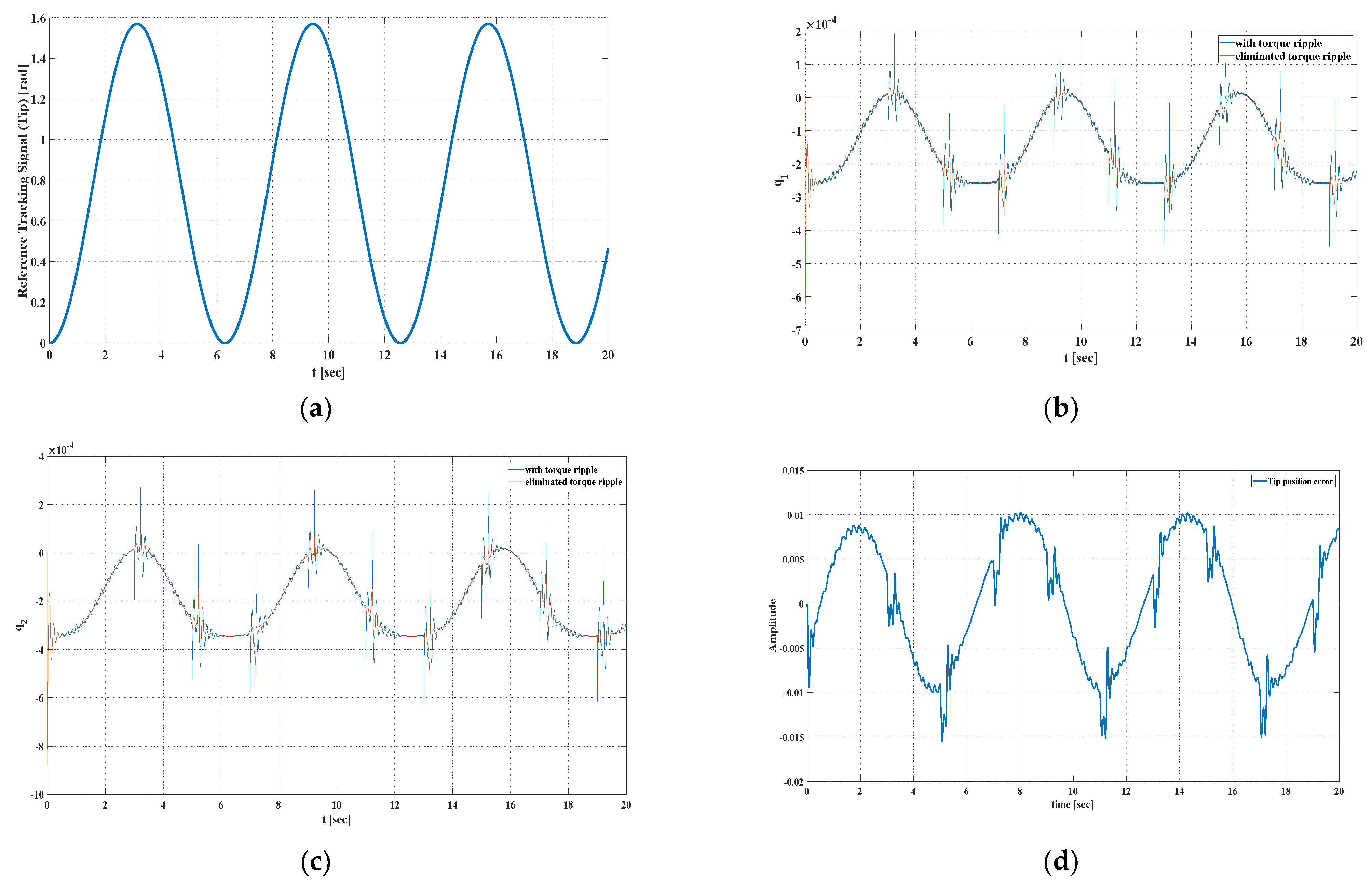
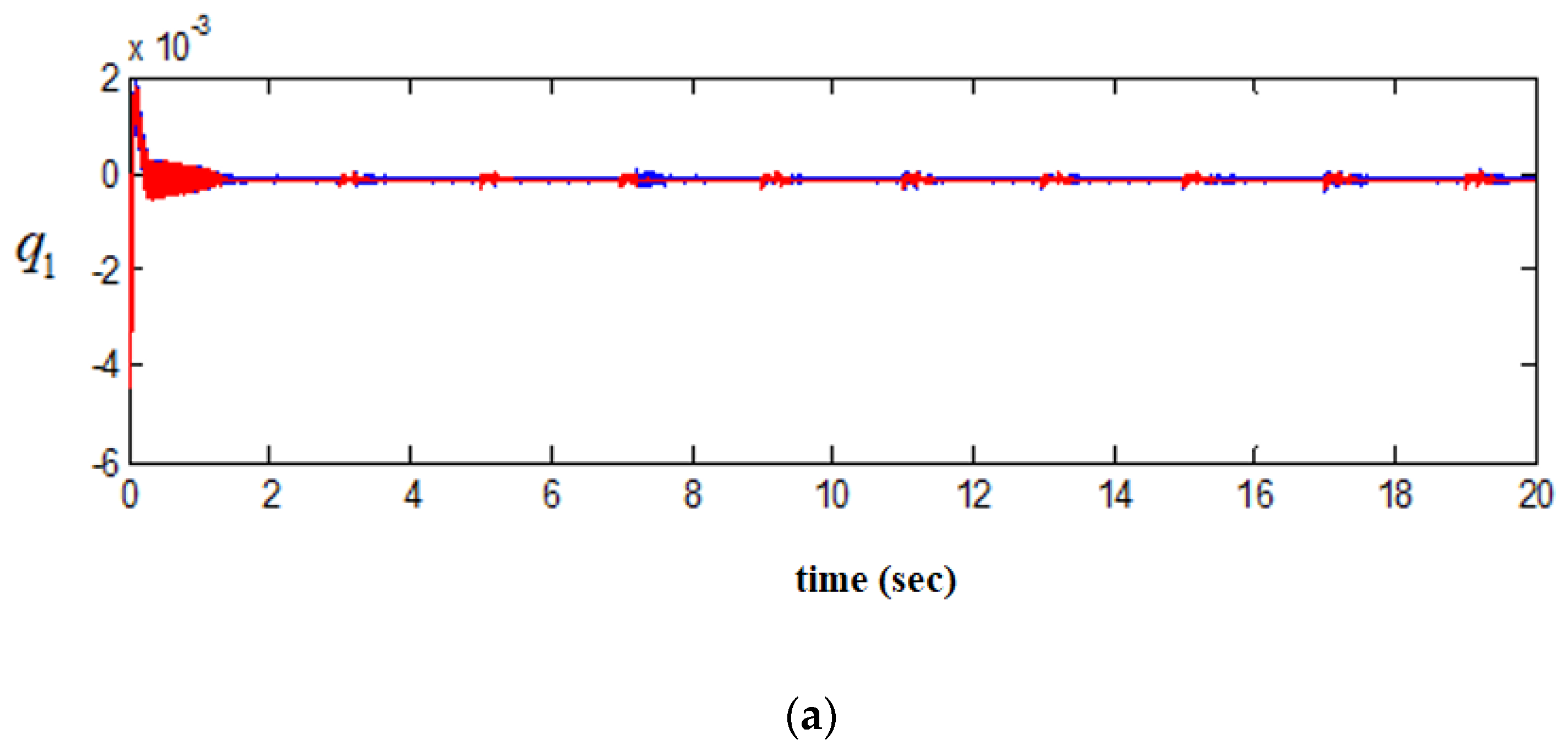
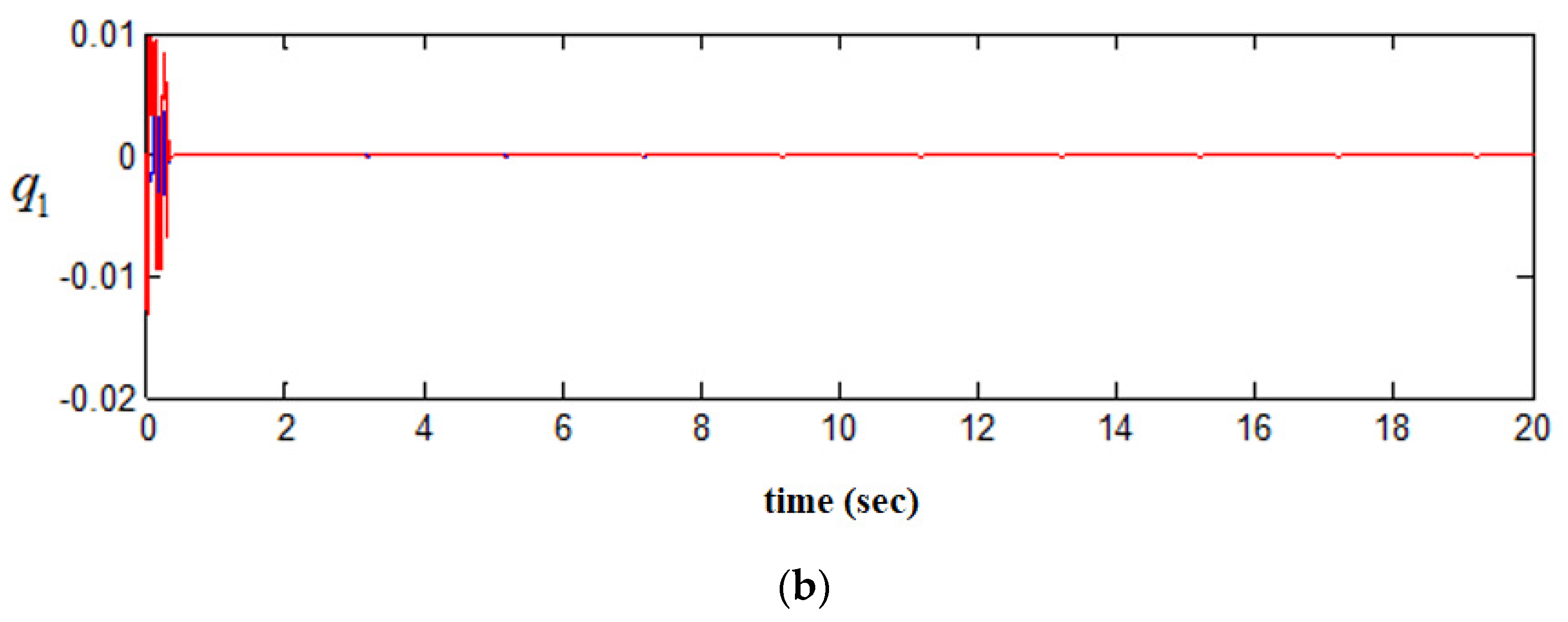
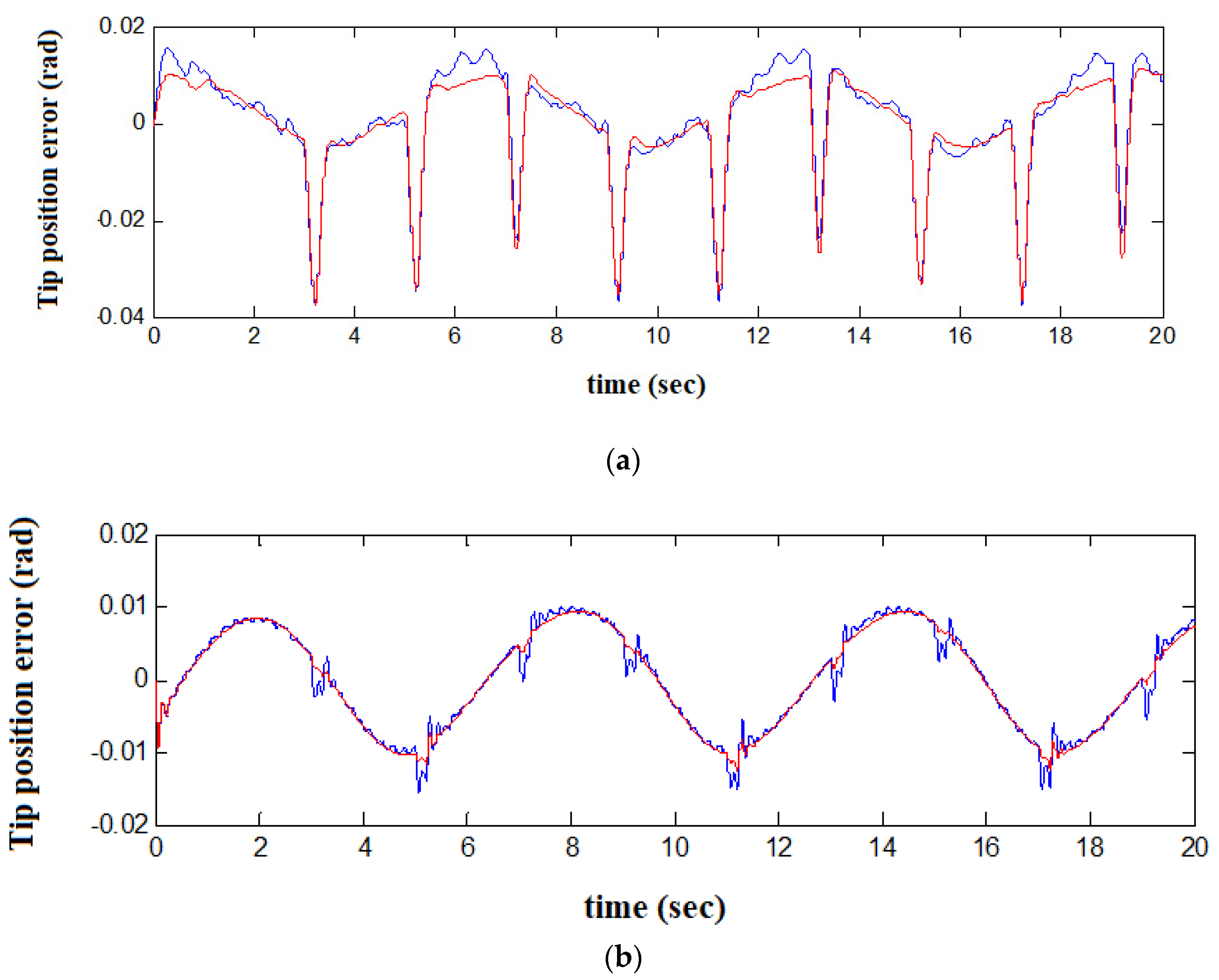
4. Simulation Results

The simulation results of the designed robust-adaptive linearizing controller are presented below. The simulation was conducted in Matlab/Simulink with an ode4 (Runge-Kutta) solver and 1e-3 fixed step size. The manipulator was constructed from two flexible links connected by a rigid joint. The joint actuators were selected as a permanent-magnet synchronous motor (PMSM). The simulations performed for control methods were evaluated under the same disturbance effect, which is reflected in the system by the displacement of the moving mass. To demonstrate the performance improvement achieved with its compensations for both set-point and tracking control, the case with no compensation was also presented. Simulations were conducted for both step-type and sinusoidal-type end-point references to show the control scheme performances for both set point and tracking control while subjected to a periodic disturbance that has a pulse characteristic (presented in Figure 4 and Figure 5).
Simulation results are obtained for the implementation of the robust-adaptive linearizing control law on a 2 DOF, DD arm subject to disturbances represented with a periodic pulse signal. In the simulations, for simplicity, only cogging torque compensation is taken into consideration, as it is the only torque component that is independent of the current dynamics. To demonstrate the performance improvement achieved with its compensations for both set-point and tracking control, we also presented results with no compensation for both cases.
Extra simulations with a Proportional-Derivative (PD)-based linearizing controller were performed for both step-type and sinusoidal type end-point references to demonstrate the performance of the proposed control scheme for both set point and tracking control in Figure 6 and Figure 7.
Inspection of the results demonstrates the significant improvement made with the robust adaptive linearization-based chattering-free SMC for set-point and tracking control, in terms of both transient and steady-state precision.
The error variations of the calculated speed and position are sufficient and consistent with the rest of the results. It should be captured and inferred from the figures that all transitions can ensure a smooth transition of motor currents without any significant impact, ensuring the smooth transition of the torque and operational stability. The smooth transition mechanisms that exist in the literature i.e., Current Harmonic Minimum PWM, Selected Harmonic Elimination PWM, Hybrid Synchronized PWM, Space Vector PWM etc. can also be considered for further investigation. Because of the flexibility of the link, rotating the base of the link causes the entire link to oscillate. The control problem is to move the tip of the link to the desired setpoint by applying a control input at the base of the link. This is a classic example of non-collocated control; i.e., the actuator is located away from the point it is controlling (the tip). Classic control methodologies such as PD and PID strategies can only be used to control the motor position. These control techniques essentially ignore the flexibility of the link, and hence, the position response exhibits lightly damped oscillatory behaviour. To quickly and effectively remove the vibrations from the system, it is necessary to incorporate the position of the tip into the control scheme. Several such control strategies (i.e., bounded input discrete-time H-2 control, H-infinity control, passive control, fuzzy control, and closed-loop shaped-input control) were successfully implemented on the link (i.e., [73,74,75,76,77,78,79]. These control strategies will not provide adequate performance if the payload mass is varied.

5. Conclusive Summary and Discussion

The implementation of SMC based on chattering-free control input, for which realistic applications are rather rare, was done in this paper. To exploit the well-known robustness properties of SMC concerning internal and external disturbances, while also improving accuracy and eliminating the unwanted chattering effects, a robust-adaptive linearization control scheme combining continuous SMC was proposed. As an underactuated system with heavy uncertainties, a flexible robot arm was modelled and simulated for designing a high-precision control system. Structural flexibilities, a high number of passive DOFs arising from a variety of operation modes, and gravitational effects were taken into consideration when concerning high-speed operation and accuracy. Actuator dynamics with inverter switching effects, current dynamics, and torque pulsations were also investigated due to the high-performance controller demands that handle modelling errors arising from parameter and model uncertainties, and sources that could excite unmodeled dynamics. Besides, zero dynamic stability was analyzed. The deteriorating effects of torque pulsations on system performance and the improved performance achieved with their compensations were also demonstrated. The results taken under disturbances simulated via pulse functions demonstrate significant improvements in terms of trajectory tracking control and set-point control. This paper also presents an in-depth analysis of finite-time convergence, stability, and robustness issues for the application of SMC to systems with heavy uncertainties. The conventional application with discontinuous input was also modified with the inclusion of the actuator dynamics. The developed method appears to have significant value in terms of increasing practical applications in nonlinear flexible robot dynamics and control. The equivalent circuit model and dynamic model of the PMSM motor was utilized to understand the current and torque shock generation mechanism. A specific scheme was constructed to see the smooth transition in hybrid PWM among various modulation modes in the full speed range by proving the feasibility and correctness of the scheme experimentally. The extent dynamics and disturbances (i.e., harmonic distortion, harmonic spectrum) considered in the simulations appear satisfactory for performance evaluation. The drawback of this paper is the lack of experimental results, but the system and the extent of dynamics and disturbances considered in the simulations appear satisfactory for performance evaluation. The main difference from the literature is that in this paper, the internal dynamics of the regressor (for the torque pulsations, gravity force, and friction torque) were proven to be persistently exciting for nonzero velocity; thus, for online adaptation of parameters, particularly for set-point tracking, the problem of parameter drift was also taken into consideration. Stability analysis of the zero dynamics arising from the passive DOFs was performed for each controller and the system output.

Funding

This research received no external funding.

Data Availability Statement

The study did not report any data.

Conflicts of Interest

The authors declare that there are no conflict of interest.

References

  1. Martínez, S.; Cortés, J.; Bullo, F. Motion planning and control problems for underactuated robots. Control. Probl. Robot. 2003, 4, 59–74. [Google Scholar]
  2. Bergerman, M.; Lee, C.; Xu, Y. Experimental Study of an Underactuated Manipulator; Carnegie Mellon University, The Robotics Institute: Pittsburgh, PA, USA, 1995. [Google Scholar]
  3. De Luca, A.; Lanari, L.; Ulivi, G.; Conte, G.; Perdon, A.M.; Wyman, B. Nonlinear regulation of end-effector motion for a flexible robot arm. New Trends Syst. Theory 1991, 7, 229–236. [Google Scholar]
  4. Chen, H.; Sun, N. Nonlinear control of underactuated systems subject to both actuated and unactuated state constraints with experimental verification. IEEE Trans. Ind. Electron. 2020, 67, 7702–7714. [Google Scholar] [CrossRef]
  5. Han, J.; Yang, S.; Xia, L.; Chen, Y. A Novel Trajectory Tracking Control Strategy for Underactuated Quadrotor UAV with Uncertainties and Disturbances. 2020. Available online: https://www.researchsquare.com/article/rs-18838/v1 (accessed on 25 March 2020).
  6. Din, S.U.; Khan, Q.; Rehman, F.U.; Akmeliawati, R. Robust control of underactuated systems: Higher order integral sliding mode approach. Math. Probl. Eng. 2016, 2016, 1–11. [Google Scholar] [CrossRef]
  7. Ovalle, L.; Rios, H.; Llama, M. Continuous sliding-mode control for a class of underactuated systems. In Proceedings of the IEEE 58th Conference on Decision and Control (CDC), Nice, France, 11–13 December 2019. [Google Scholar]
  8. Rudra, S.; Barai, R.K.; Maitra, M. Challenges and new frontiers in the field of underactuated mechanical systems control. In Block Backstepping Design of Nonlinear State Feedback Control Law for Underactuated Mechanical Systems; Springer: Berlin/Heidelberg, Germany, 2016; pp. 145–153. [Google Scholar]
  9. Tuan, L.A.; Lee, S.-G. Nonlinear feedback control of underactuated mechanical systems. In Nonlinear Systems—Design, Analysis, Estimation and Control; Springer: Berlin/Heidelberg, Germany, 2016. [Google Scholar]
  10. Xu, R.; Özgüner, Ü. Sliding mode control of a class of underactuated systems. Automatica 2008, 44, 233–241. [Google Scholar] [CrossRef]
  11. Krafes, S.; Chalh, Z.; Saka, A. A review on the control of second order underactuated mechanical systems. Complexity 2018, 2018, 9573514. [Google Scholar] [CrossRef]
  12. Lai, X.; Xiong, P.; Wu, M. Stable control strategy for a second-order nonholonomic planar underactuated mechanical system. Int. J. Syst. Sci. 2019, 50, 2126–2141. [Google Scholar] [CrossRef]
  13. Jaritz, A.; Spong, M.W. An experimental comparison of robust control algorithms on a direct drive manipulator. IEEE Trans. Control. Syst. Technol. 1996, 4, 627–640. [Google Scholar] [CrossRef]
  14. Reyes-Cortes, F.; Kelly, R. Experimental evaluation of model-based controllers on a direct-drive robot arm. Mechatronics 2001, 11, 267–282. [Google Scholar] [CrossRef]
  15. Ullah, M.I.; Ajwad, S.A.; Irfan, M.; Iqbal, J. MPC and H-Infinity based feedback control of non-linear robotic manipulator. In Proceedings of the 2016 International Conference on Frontiers of Information Technology (FIT), Islamabad, Pakistan, 19–21 December 2016. [Google Scholar]
  16. Cheah, C.C.; Liu, C.; Slotine, J. Adaptive jacobian tracking control of robots with uncertainties in kinematic, dynamic and actuator models. IEEE Trans. Autom. Control. 2006, 51, 1024–1029. [Google Scholar] [CrossRef]
  17. Zhou, B.; Yang, L.; Wang, C.; Chen, Y.; Chen, K. Inverse jacobian adaptive tracking control of robot manipulators with kinematic, dynamic, and actuator uncertainties. Complexity 2020, 2020, 5070354. [Google Scholar] [CrossRef]
  18. Aghili, F.; Buehler, M.; Hollerbach, J. Dynamics and control of direct-drive robots with positive joint torque feedback. In Proceedings of the International Conference on Robotics and Automation, Albuquerque, NM, USA, 25 April 1997. [Google Scholar]
  19. Jiang, L.; Gao, B.; Zhu, Z. Design and nonlinear control of a 2-DOF flexible parallel humanoid arm joint robot. Shock. Vib. 2017, 2017, 2762169. [Google Scholar] [CrossRef] [Green Version]
  20. Petridis, A.G.; Kanarachos, A.E. Response optimization of a nonlinear controlled flexible robot arm carrying a variable mass. In Progress in System and Robot Analysis and Control Design Lecture Notes in Control and Information Sciences; Springer: Berlin/Heidelberg, Germany, 2007; pp. 465–476. [Google Scholar]
  21. Ansarieshlaghi, F.; Eberhard, P. Experimental study on a nonlinear observer application for a very flexible parallel robot. Int. J. Dyn. Control. 2018, 7, 1046–1055. [Google Scholar] [CrossRef]
  22. Cambera, J.C.; Feliu-Batlle, V. Input-state feedback linearization control of a single-link flexible robot arm moving under gravity and joint friction. Robot. Auton. Syst. 2017, 88, 24–36. [Google Scholar] [CrossRef]
  23. Sayahkarajy, M.; Mohamed, Z.; Faudzi, A.A.M. Review of modelling and control of flexible-link manipulators. Proc. Inst. Mech. Eng. Part I J. Syst. Control. Eng. 2016, 230, 861–873. [Google Scholar] [CrossRef]
  24. Arısoy, A.; Gokasan, M.; Bogosyan, O. Esnek-mafsallı robot kolun yüksek dereceli kayma kipli kontrolü. İTÜDERGISI/d 2011, 9, 1. [Google Scholar]
  25. Gokasan, M.; Bogosyan, O.S.; Sabanovic, A.; Arabyan, A. A sliding mode observer and controller for a single link flexible arm. In Proceedings of the 37th IEEE Conference on Decision and Control, Tampa, FL, USA, 18 December 1998. [Google Scholar]
  26. Kostic, D.; Jager, B.D.; Steinbuch, M. Robust attenuation of direct-drive robot-tip vibrations. In Proceedings of the IEEE/RSJ International Conference on Intelligent Robots and System, Lausanne, Switzerland, 30 September–4 October 2002. [Google Scholar]
  27. Li, Y.; Tong, S.; Li, T. Adaptive fuzzy output feedback control for a single-link flexible robot manipulator driven DC motor via backstepping. Nonlinear Anal. Real World Appl. 2013, 14, 483–494. [Google Scholar] [CrossRef]
  28. Uecker, D.R.; Wang, Y.; Kokkinis, T. Experimental evaluation of real-time model-based control of a 3-DOF closed-chain direct-drive mechanism. In Proceedings of the 1991 IEEE International Conference on Robotics and Automation, Sacramento, CA, USA, 9–11 April 1991. [Google Scholar]
  29. Ayten, K.K.; Dumlu, A. Real-time ımplementation of sliding mode control technique for two-DOF ındustrial robotic arm. J. Inst. Sci. Technol. 2018, 8, 77–85. [Google Scholar] [CrossRef] [Green Version]
  30. Azizi, Y.; Yazdizadeh, A. Passivity-based adaptive control of a 2-DOF serial robot manipulator with temperature dependent joint frictions. Int. J. Adapt. Control. Signal Process. 2019, 33, 512–526. [Google Scholar] [CrossRef]
  31. Santibanez, V.; Kelly, R.; Llama, M. A novel global asymptotic stable set-point fuzzy controller with bounded torques for robot manipulators. IEEE Trans. Fuzzy Syst. 2005, 13, 362–372. [Google Scholar] [CrossRef]
  32. Naayagi, R.; Kamaraj, V. Minimization of torque ripple in switched reluctance machine for direct drive applications. In Proceedings of the IEEE Symposium on Emerging Technologies, Islamabad, Pakistan, 18 September 2005. [Google Scholar]
  33. Fei, Q.; Deng, Y.; Li, H.; Liu, J.; Shao, M. Speed ripple minimization of permanent magnet synchronous motor based on model predictive and ıterative learning controls. IEEE Access 2019, 7, 31791–31800. [Google Scholar] [CrossRef]
  34. Matsui, N. Autonomous torque ripple compensation of DD motor by torque observer. In Proceedings of the Proceedings 1993 Asia-Pacific Workshop on Advances in Motion Control, Singapore, 15–16 July 1993. [Google Scholar]
  35. Şahin, A.; Öner, Y. High efficient permanent magnet synchronous motor design, electromagnetic and noise-vibration analyzes. Balk. J. Electr. Comput. Eng. 2021, 9, 83–91. [Google Scholar] [CrossRef]
  36. Aghili, F.; Buehler, M.; Hollerbach, J. Torque ripple minimization in direct-drive systems. In Proceedings of the 1998 IEEE/RSJ International Conference on Intelligent Robots and Systems. Innovations in Theory, Practice and Applications, Victoria, BC, Canada, 17 October 1998. [Google Scholar]
  37. Pandya, S.N.; Chatterjee, J.K. Torque ripple minimization in direct torque control based induction motor drive using optimal multirate sampling technique. In Proceedings of the 2010 Joint International Conference on Power Electronics, Drives and Energy Systems & 2010 Power India, New Delhi, India, 20–23 December 2010. [Google Scholar]
  38. Petrovic, V.; Ortega, R.; Stankovic, A.; Tadmor, G. Design and implementation of an adaptive controller for torque ripple minimization in PM synchronous motors. IEEE Trans. Power Electron. 2000, 15, 871–880. [Google Scholar] [CrossRef]
  39. Fei, W.; Luk, P. A new technique of cogging torque suppression in direct-drive permanent-magnet brushless machines. IEEE Trans. Ind. Appl. 2010, 46, 1332–1340. [Google Scholar] [CrossRef] [Green Version]
  40. Almakhles, D.J. Robust backstepping sliding mode control for a quadrotor trajectory tracking application. IEEE Access 2020, 8, 5515–5525. [Google Scholar] [CrossRef]
  41. Petrovic, V.; Ortega, R.; Stankovic, A.; Tadmor, G. An adaptive controller for minimization of torque ripple in PM synchronous motors. In Proceedings of the PESC 98 Record. 29th Annual IEEE Power Electronics Specialists Conference (Cat. No.98CH36196), Fukuoka, Japan, 22 May 1998. [Google Scholar]
  42. Krener, A.J. Differential geometric methods in nonlinear control. Encycl. Syst. Control. 2015, 8, 275–284. [Google Scholar]
  43. Xin, X.; Yamasaki, T. Energy-based swing-up control for a remotely driven Acrobot: Theoretical and experimental results. IEEE Trans. Control. Syst. Technol. 2012, 20, 1048–1056. [Google Scholar] [CrossRef]
  44. Guo, W.; Liu, D. Nonlinear recursive design for the underactuated IWP system. J. Appl. Res. Technol. 2014, 12, 602–606. [Google Scholar] [CrossRef]
  45. Arteaga, M.; Siciliano, B. On tracking control of flexible robot arms. IEEE Trans. Autom. Control. 2000, 45, 520–527. [Google Scholar] [CrossRef]
  46. Chang, Y.-C.; Chen, B.-S.; Lee, T.-C. Tracking control of flexible joint manipulators using only position measurements. Int. J. Control. 1996, 64, 567–593. [Google Scholar] [CrossRef]
  47. Liu, H.; Huang, Y.; Wu, W. Improved adaptive output feedback controller for flexible-joint robot manipulators. In Proceedings of the IEEE International Conference on Information and Automation (ICIA), Ningbo, China, 1–3 August 2016. [Google Scholar]
  48. Loria, A.; Avila-Becerril, S. Output-feedback global tracking control of robot manipulators with flexible joints. In Proceedings of the American Control Conference, Portland, OR, USA, 4–6 June 2014. [Google Scholar]
  49. Park, J.; Chang, P.-H.; Park, H.-S.; Lee, E. Design of learning input shaping technique for residual vibration suppression in an industrial robot. IEEE/ASME Trans. Mechatron. 2006, 11, 55–65. [Google Scholar] [CrossRef]
  50. Markus, E.D. Flatness based feed-forward control of a flexible robot arm under gravity and joint friction. In Proceedings of the 12th International Conference on Informatics in Control, Automation and Robotics, Colmar, France, 21–23 July 2015. [Google Scholar]
  51. Mansor, N.N.; Jamaluddin, M.H.; Shukor, A.Z.; Lok, C.C. A study of accuracy and time delay for bilateral master-slave ındustrial robotic arm manipulator system. MATEC Web Conf. 2018, 150, 1015. [Google Scholar] [CrossRef] [Green Version]
  52. Yang, J.H.; Lian, F.-L.; Fu, L.-C. Nonlinear adaptive control for flexible-link manipulators. IEEE Trans. Robot. Autom. 1997, 13, 140–148. [Google Scholar] [CrossRef]
  53. Arisoy, A.; Gokasan, M.; Bogosyan, O. Partial feedback linearization control of a single flexible link robot manipulator. In Proceedings of the 2nd International Conference on Recent Advances in Space Technologies, 2005 RAST 2005, Istanbul, Turkey, 9–11 June 2005. [Google Scholar]
  54. Liu, L.-Y.; Yuan, K. Noncollocated passivity-based PD control of a single-link flexible manipulator. Robotica 2003, 21, 117–135. [Google Scholar] [CrossRef]
  55. Mattioni, A.; Wu, Y.; Le Gorrec, Y. Infinite dimensional model of a double flexible-link manipulator: The port-hamiltonian approach. Appl. Math. Model. 2020, 83, 59–75. [Google Scholar] [CrossRef]
  56. Meurer, T.; Thull, D.; Kugi, A. Flatness-based tracking control of a piezoactuated Euler–Bernoulli beam with non-collocated output feedback: Theory and experiments†. Int. J. Control. 2008, 81, 475–493. [Google Scholar] [CrossRef]
  57. Han, L.; Chen, M.; Wu, Q.; Li, X. Sliding mode control using disturbance observer for a flexible link robot. In Proceedings of the 14th International Workshop on Variable Structure Systems (VSS), Nanjing, China, 1–4 June 2016. [Google Scholar]
  58. Sinha, A.; Mishra, R.K. Smooth sliding mode controller design for robotic arm. In Proceedings of the 2013 International Conference on Control, Automation, Robotics and Embedded Systems (CARE), Jabalpur, India, 16–18 December 2013. [Google Scholar]
  59. Hosaka, M.; Murakami, T. Vibration control of flexible arm by multiple observer structure. Electr. Eng. Jpn. 2006, 154, 68–75. [Google Scholar] [CrossRef]
  60. Lochan, K.; Roy, B.; Subudhi, B. SMC controlled chaotic trajectory tracking of two-link flexible manipulator with PID sliding surface. IFAC-PapersOnLine 2016, 49, 219–224. [Google Scholar] [CrossRef]
  61. Jin, Q.-B.; Liu, Q.; Wang, Q.; Li, S.-N.; Wang, Z. IMC-PID design: Analytical optimization for performance/robustness tradeoff tuning for servo/regulation mode. Asian J. Control. 2013, 16, 1252–1261. [Google Scholar] [CrossRef]
  62. Montazeri, A.; Poshtan, J.; Choobdar, A. Performance and robust stability trade-off in minimax LQG control of vibrations in flexible structures. Eng. Struct. 2009, 31, 2407–2413. [Google Scholar] [CrossRef]
  63. Farahmandrad, M.; Ganjefar, S.; Talebi, H.A.; Bayati, M. Design of higher-order sliding mode controller based on genetic algorithm for a cooperative robotic system. Int. J. Dyn. Control. 2019, 8, 269–277. [Google Scholar] [CrossRef]
  64. Mujumdar, A.; Kurode, S.; Tamhane, B. Control of two link flexible manipulator using higher order sliding modes and disturbance estimation. IFAC Proc. Vol. 2014, 47, 95–102. [Google Scholar] [CrossRef]
  65. Alandoli, E.A.; Lee, T.S. A critical review of control techniques for flexible and rigid link manipulators. Robotica 2020, 38, 2239–2265. [Google Scholar] [CrossRef]
  66. Souza, A.G.; Souza, L.C. H Infinity Attitude Controller Design for a Rigid-Flexible Satellite Considering the Parametric Uncertainty; SAE Technical Paper Series: New York, NY, USA, 2016. [Google Scholar]
  67. Yu, Z.; Chen, H.; Woo, P.-Y. Polytopic gain scheduled H control for robotic manipulators. Robotica 2003, 21, 495–504. [Google Scholar] [CrossRef]
  68. Toussaint, G.; Basar, T.; Bullo, F. Motion planning for nonlinear underactuated vehicles using H∞ techniques. In Proceedings of the 2001 American Control Conference. (Cat. No.01CH37148), Arlington, VA, USA, 25–27 June 2001. [Google Scholar]
  69. Ali, H.I.; Abdulridha, A.J. H-infinity sliding mode controller design for a human swing leg system. Al-Nahrain J. Eng. Sci. 2020, 23, 117–126. [Google Scholar] [CrossRef]
  70. Ye, D.; Zou, A.-M.; Sun, Z. Predefined-time predefined-bounded attitude tracking control for rigid spacecraft. Available online: https://ieeexplore.ieee.org/iel7/7/7778228/09512481.pdf (accessed on 1 January 2021).
  71. Xiao, Y.; De Ruiter, A.; Ye, D.; Sun, Z. Adaptive fault-tolerant attitude tracking control for flexible spacecraft with guaranteed performance bounds. IEEE Trans. Aerosp. Electron. Syst. 2021, 1. [Google Scholar] [CrossRef]
  72. Mareels, I.M.Y.; Gevers, M. Persistency of excitation criteria for linear, multivariable, time-varying systems. Math. Control. Signals Syst. 1988, 1, 203–226. [Google Scholar] [CrossRef]
  73. Altıner, B.; Delibasi, A.; Erol, B. Modeling and control of flexible link manipulators for unmodeled dynamics effect. Proc. Inst. Mech. Eng. Part I J. Syst. Control. Eng. 2018, 233, 245–263. [Google Scholar] [CrossRef]
  74. Karkoub, M.; Tamma, K. Modelling and μ-synthesis control of flexible manipulators. Comput. Struct. 2001, 79, 543–551. [Google Scholar] [CrossRef]
  75. Krishnan, H.; Vidyasagar, M. Bounded input feedback control of linear systems with application to the control of a flexible system. In Proceedings of the 27th IEEE Conference on Decision and Control, Austin, TX, USA, 7–9 December 1988. [Google Scholar] [CrossRef]
  76. Kuo, K.; Lin, J. Fuzzy logic control for flexible link robot arm by singular perturbation approach. Appl. Soft Comput. 2002, 2, 24–38. [Google Scholar] [CrossRef]
  77. Lin, J.; Varaiya, P. Bounded-input bounded-output stability of nonlinear time-varying discrete control systems. IEEE Trans. Autom. Control. 1967, 12, 423–427. [Google Scholar] [CrossRef]
  78. Wang, D.; Vidyasagar, M. Passive control of a stiff flexible link. Int. J. Robot. Res. 1992, 11, 572–578. [Google Scholar] [CrossRef]
  79. Zuo, K.; Drapeau, V.; Wang, D. Closed loop shaped-ınput strategies for flexible robots. Int. J. Robot. Res. 1995, 14, 510–529. [Google Scholar] [CrossRef]
Figure 1. Representation of the flexible link robot.
Vibration 05 00001 g001
Figure 2. The block diagram of the torque input has an actuator dynamics model.
Vibration 05 00001 g002
Figure 3. General block diagram of the proposed control system.
Vibration 05 00001 g003
Figure 4. Disturbance on the flexible robot arm, which is reflected as the displacement of the moving mass (a). Set-point (b,c) and tracking (d) control performance of the SMC-based adaptive linearizing control scheme concerning the step type endpoint reference (the units are in meters).
Vibration 05 00001 g004
Figure 5. A sinusoidal reference signal for tracking control (a). Set-point (b,c) and tracking (d) control performance of the SMC-based adaptive linearizing control scheme concerning the sinusoidal type endpoint reference (the units are in radian).
Vibration 05 00001 g005
Figure 6. (a) The set-point control performance of the PD based adaptive control laws; (b) the set-point control performance of the proposed SMC-based adaptive control laws for a step-type endpoint reference. (Blue: with torque ripple, Red: without torque ripple).
Vibration 05 00001 g006aVibration 05 00001 g006b
Figure 7. (a) The tracking control performance of the PD-based adaptive control laws; and (b) the tracking control performance of the proposed SMC-based adaptive control laws for a sinusoidal type endpoint reference. (Blue: with torque ripple, Red: without torque ripple).
Vibration 05 00001 g007
Table 1. The system parameters define the flexible robot arm.
Definition Notation
Gravitational constant g
Translational spring constants k 1 , k 2
Translational viscous damping constants d 1 , d 2
Rotational spring constants k Ψ 1 , k Ψ 2
Rotational viscous damping constants d Ψ 1 , d Ψ 2
Unloaded length of the links l 10 , l 20
The unloaded angle of the joints Ψ 10 , Ψ 20
Translational inertia values m 1 , m 2
Rotational inertia values J Ψ 1 , J Ψ 2
Publisher’s Note: MDPI stays neutral with regard to jurisdictional claims in published maps and institutional affiliations.

