
Spiral Bevel Gears Nonlinear Vibration Having Radial and Axial Misalignments Effects


Abstract
:1. Introduction
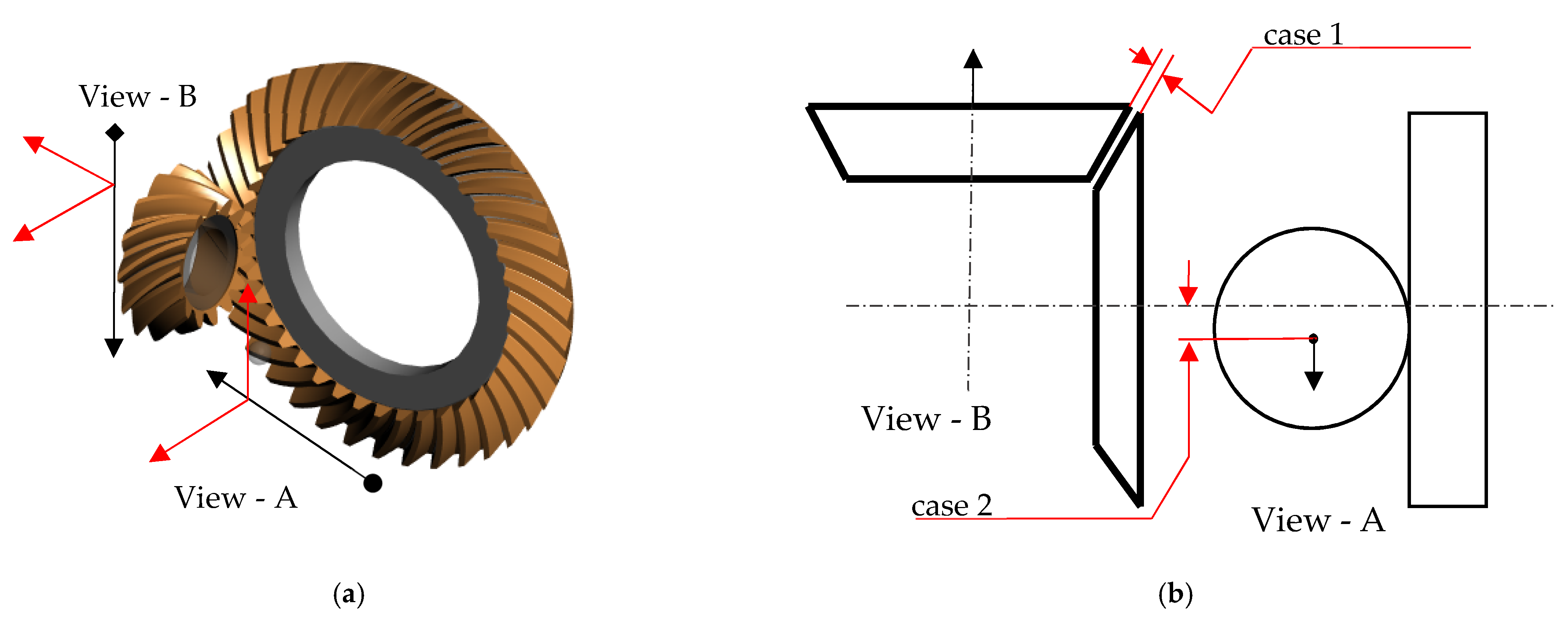
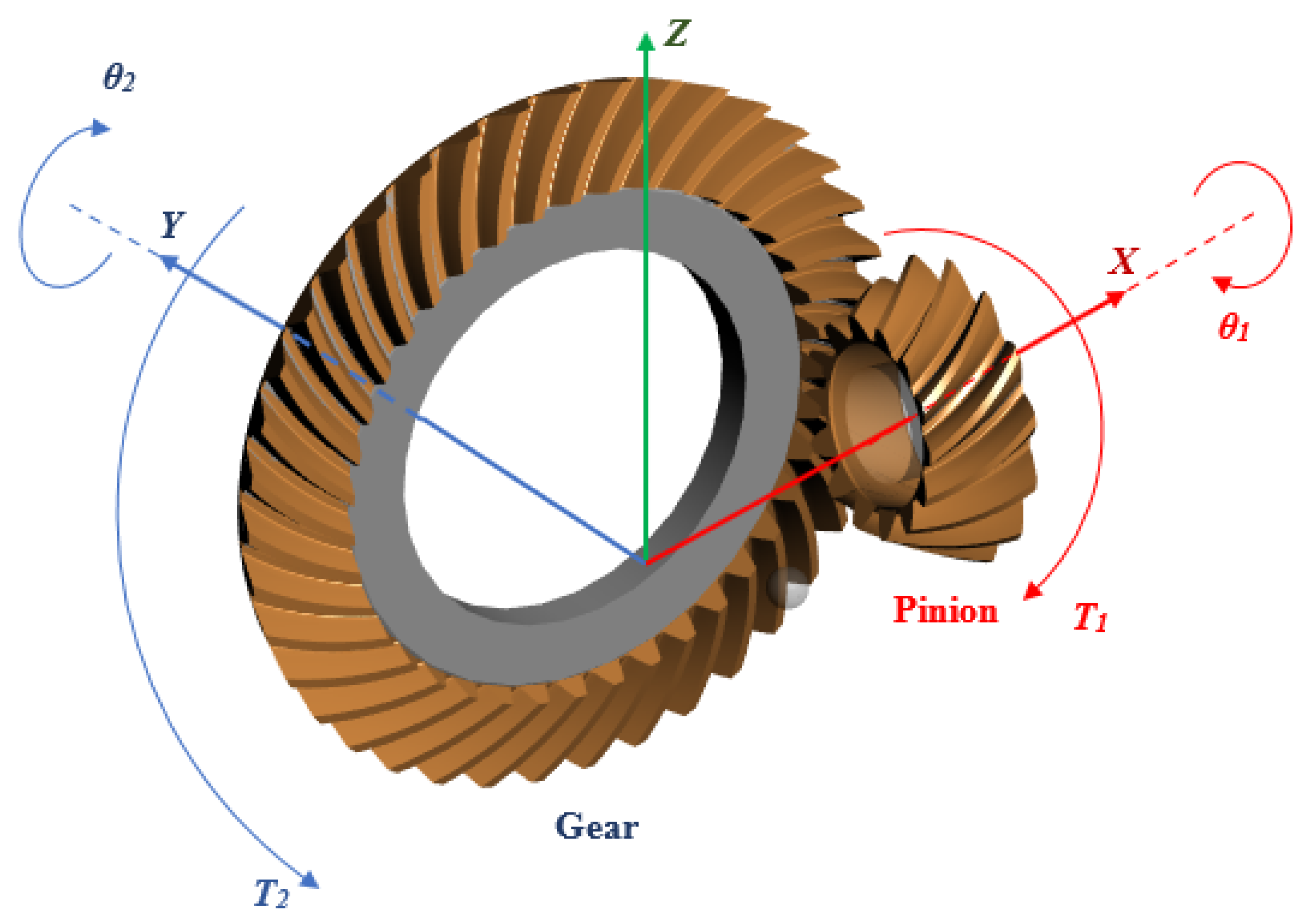
2. Physical Model
- Case 1: Axial misalignment (offset 0.01 mm);
- Case 2: Radial misalignment (offset 0.015 mm);
- Case 3: Combination of the axial and radial misalignments (0.01 mm and 0.015 mm, respectively).
3. Numerical Results
4. Conclusions
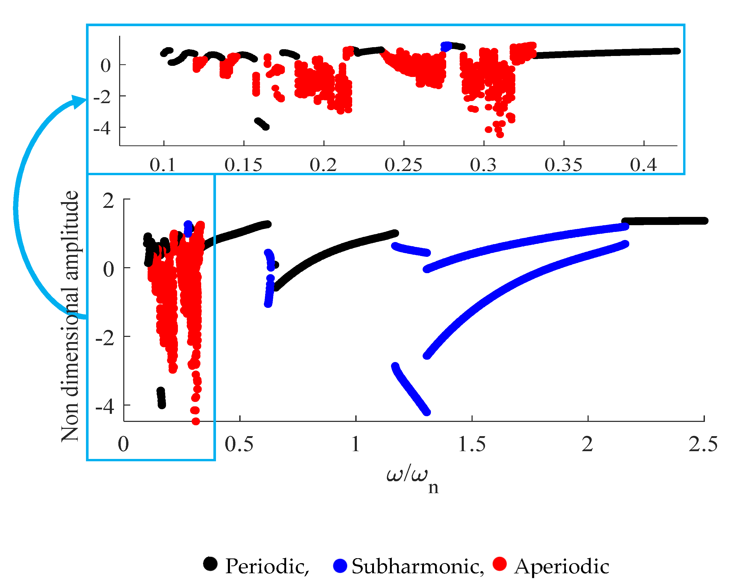
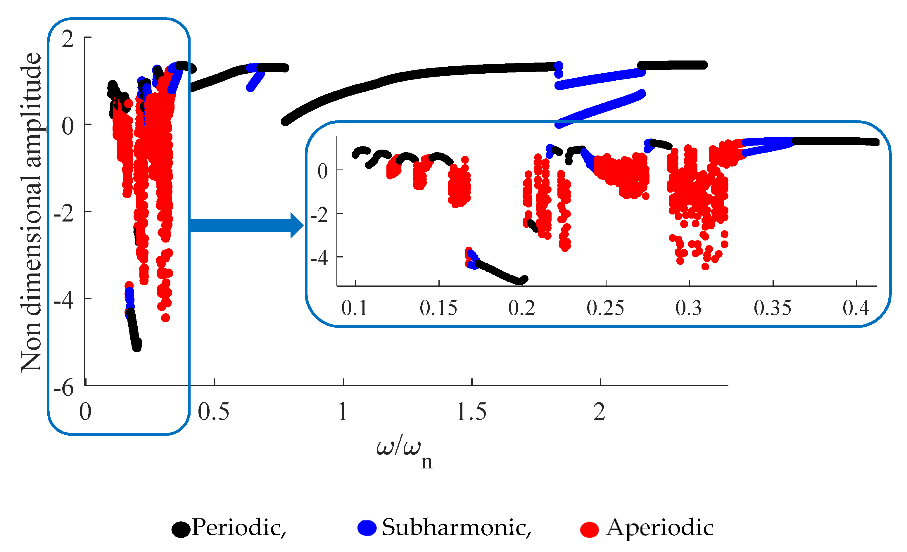
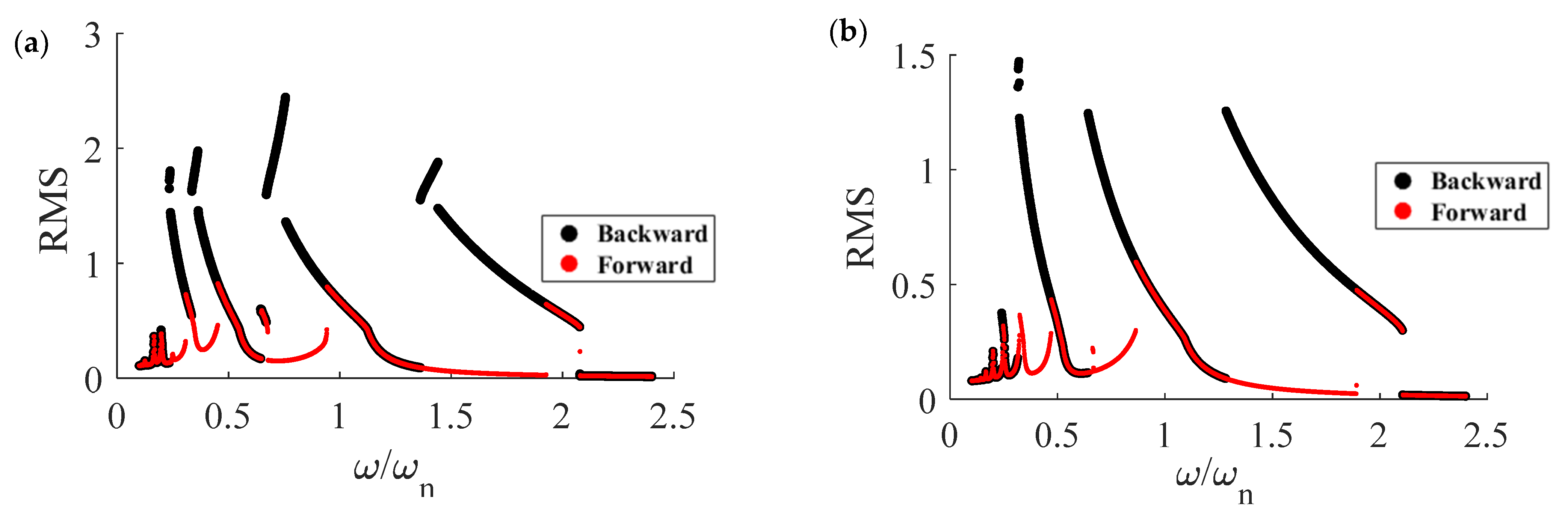
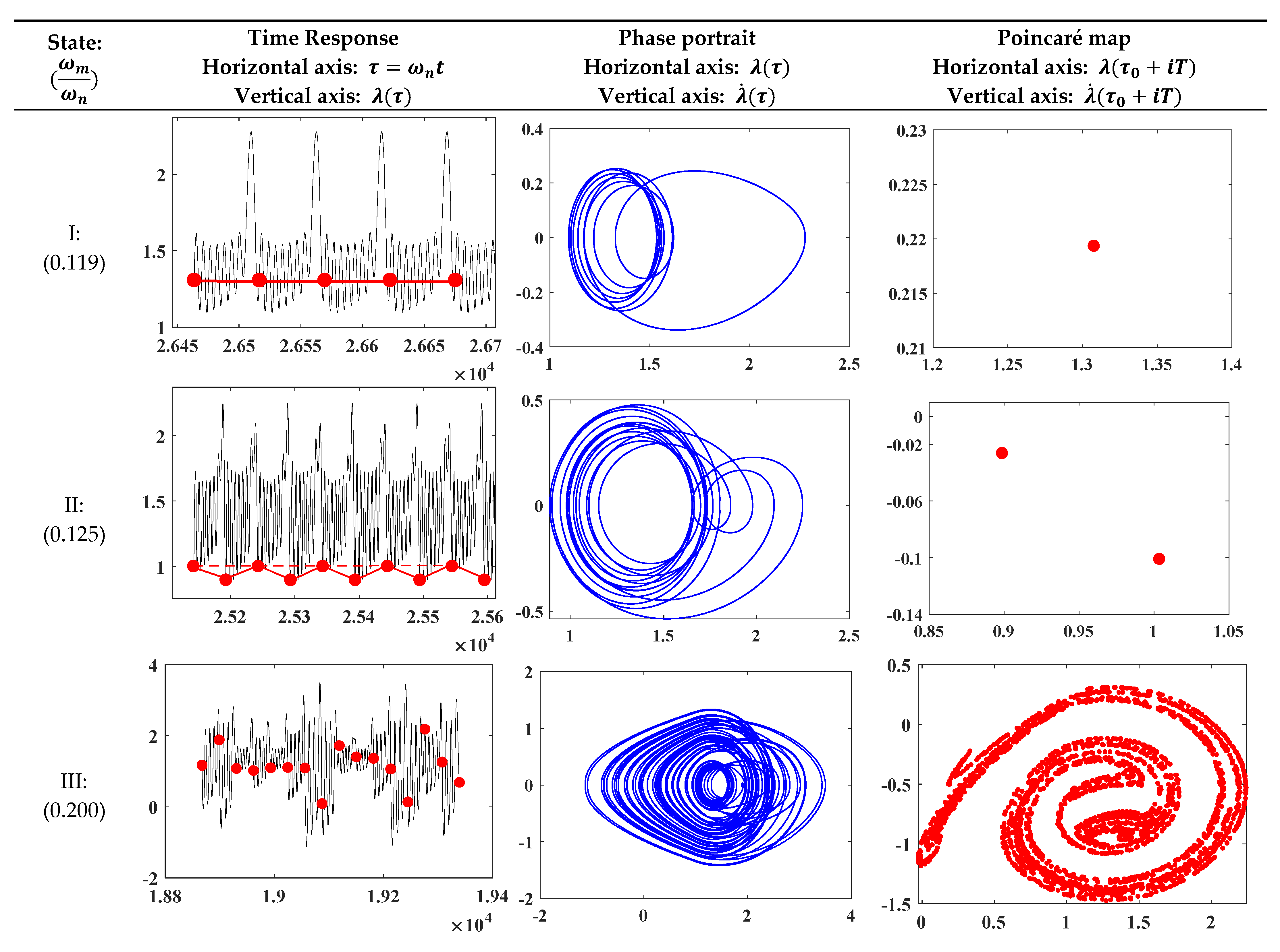
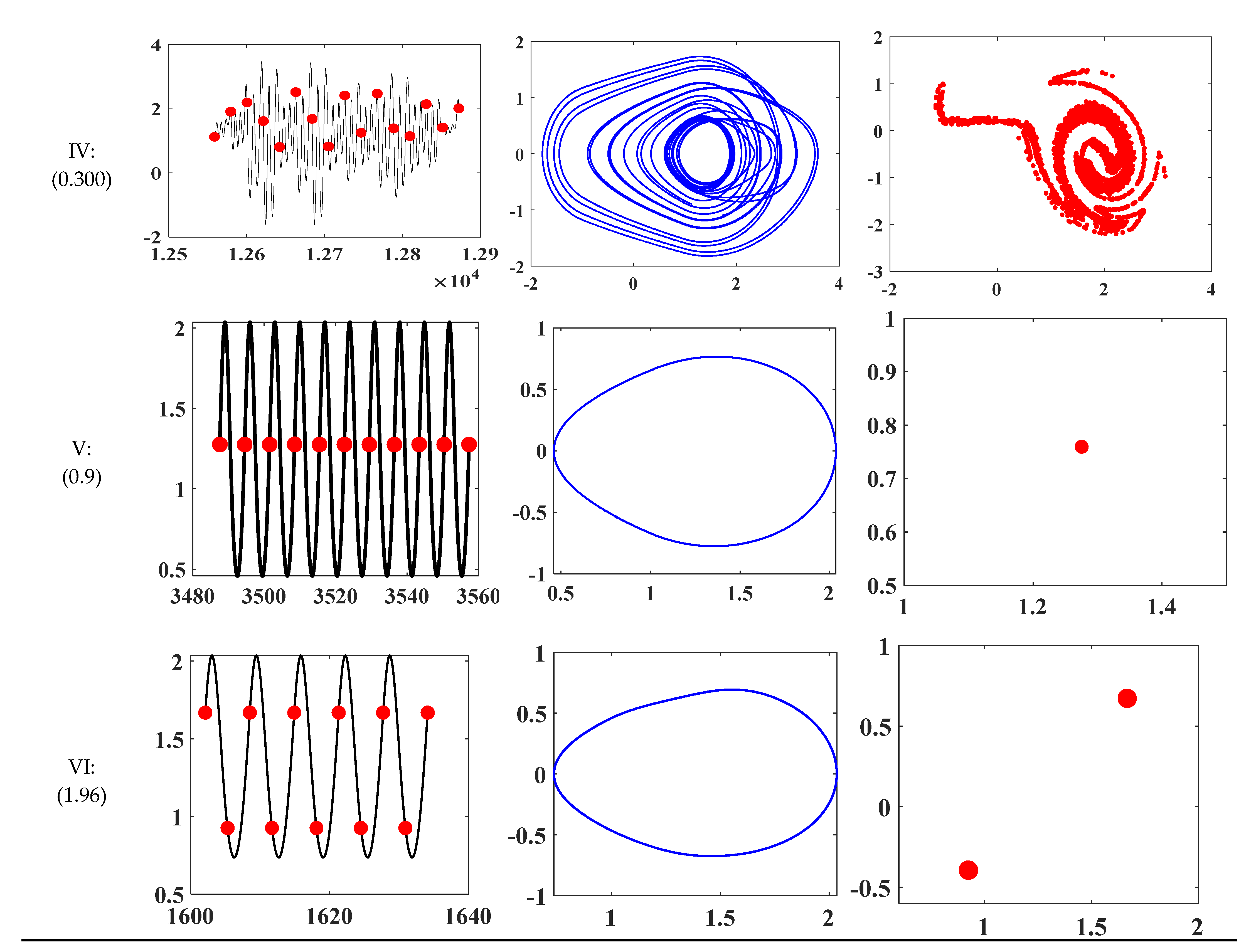
- For axial misalignment, bifurcation analysis shows three diverse scenarios: periodic, subharmonic, and aperiodic. It is notable that, while , chaotic phenomena frequently occur.
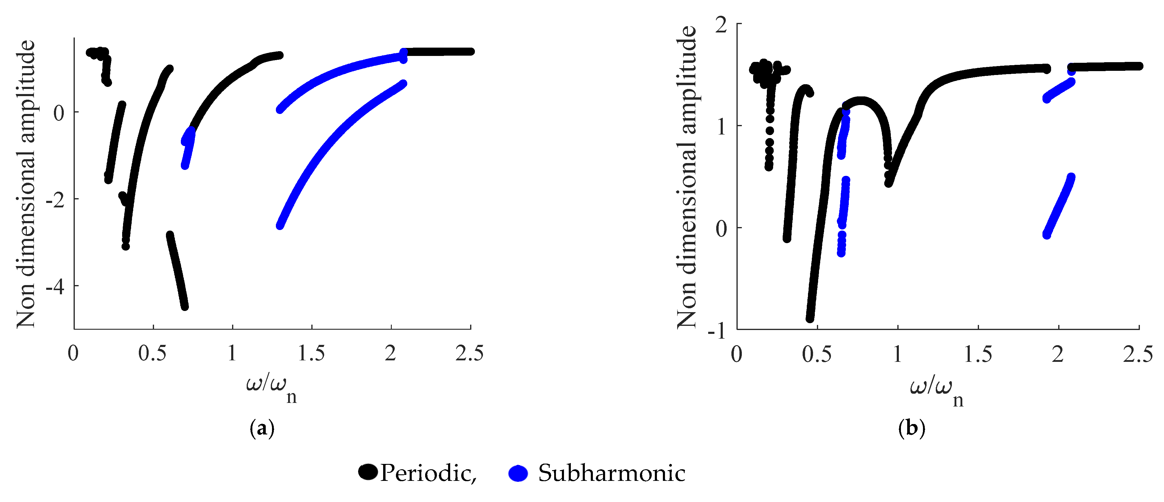
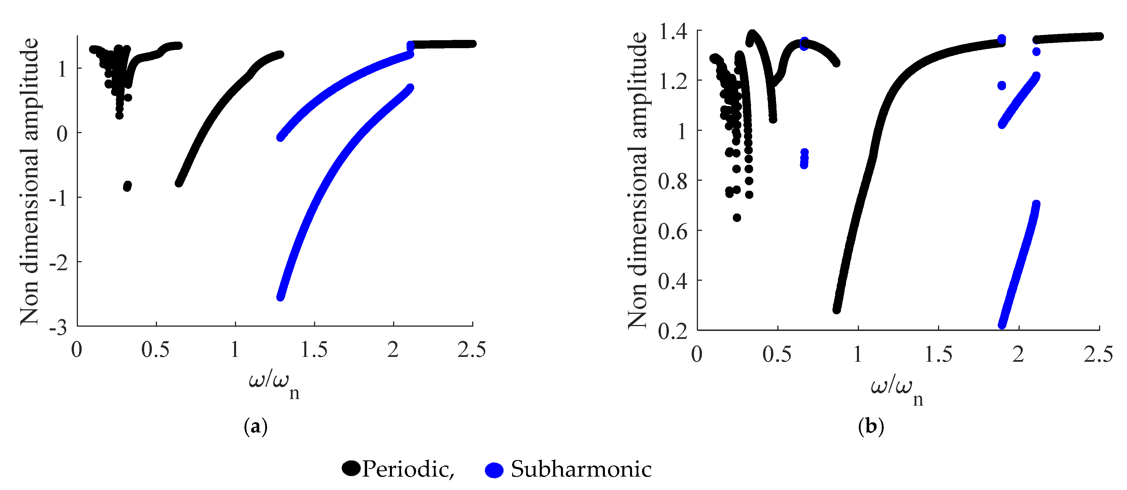
- There is no chaotic response for the case with radial misalignment and the combination of the radial and axial misalignments. These two cases have the same behavior for ; however, this behavior is completely different for .
- The third case introduces the SBG with both axial and radial misalignments; thus, it is expected that the relevant dynamic behavior is worse than the case with just axial misalignment. However, in contrast with case 1, the case with both types of considered misalignment demonstrates less chaotic responses.
Author Contributions
Funding
Institutional Review Board Statement
Informed Consent Statement
Data Availability Statement
Conflicts of Interest
Nomenclature
| aj, bj | Fourier coefficients |
| c | Damping coefficient between the mesh gear teeth of the pairs |
| Ceq | Equivalent damping coefficient |
| E | Module of elasticity |
| eθ(t) | Time-varying circumferential no-load transmission error |
| I1, I2 | Rotary inertia of pinion and gear |
| Ieq | Equivalent rotary inertia |
| N1 | Teeth number of pinion |
| n | Gear ratio of the gear pair |
| Np | Number of samples for mesh stiffness computation |
| k0 | Average value of torsional mesh stiffness of the gear pair |
| k | Time-varying mesh stiffness of the gear pair |
| Keq | Equivalent mesh stiffness of the gear pair |
| Km | Equivalents of the torsional mesh stiffness of the gear pair |
| rb1, rb2 | Base radii of pinion and gear |
| S | Number of harmonics |
| T1 | Constant driver torque |
| T2 | Constant breaking torque |
| w | Face width |
| α | Pressure angle |
| γs | Input shaft speed |
| ζ | Damping ratio |
| θ1 | Driver angular displacement |
| θ2 | Driven angular displacement |
| θb | Angular backlash |
| λ | Linear dynamic transmission error along the line of action |
| λθ | Angular dynamic transmission error |
| ν | Poisson ratio |
| ωm | Fundamental mesh frequency |
References
- Hu, Z.; Ding, H.; Peng, S.; Tang, Y.; Tang, J. Numerical determination to loaded tooth contact performances in consideration of misalignment for the spiral bevel gears. Int. J. Mech. Sci. 2019, 151, 343–355. [Google Scholar] [CrossRef]
- Molaie, M.; Samani, F.S.; Motahar, H. Nonlinear vibration of crowned gear pairs considering the effect of Hertzian contact stiffness. SN Appl. Sci. 2019, 1, 414. [Google Scholar] [CrossRef] [Green Version]
- Samani, F.S.; Molaie, M.; Pellicano, F. Nonlinear vibration of the spiral bevel gear with a novel tooth surface modification method. Meccanica 2019, 54, 1071–1081. [Google Scholar] [CrossRef]
- Özgüven, H.N.; Houser, D.R. Mathematical models used in gear dynamics—A review. J. Sound Vib. 1988, 121, 383–411. [Google Scholar] [CrossRef]
- Guo, H.; Zhang, J.; Yu, H. Dynamic modelling and parametric optimization of a full hybrid transmission. Proc. Inst. Mech. Eng. Part K J. Multi-Body Dyn. 2019, 233, 17–29. [Google Scholar] [CrossRef]
- Paouris, L.; Rahmani, R.; Theodossiades, S.; Rahnejat, H.; Hunt, G.; Barton, W. Inefficiency predictions in a hypoid gear pair through tribodynamics analysis. Tribol. Int. 2018, 119, 631–644. [Google Scholar] [CrossRef] [Green Version]
- Simon, V. Influence of tooth errors and misalignments on tooth contact in spiral bevel gears. Mech. Mach. Theory 2008, 43, 1253–1267. [Google Scholar] [CrossRef]
- Elisaus, V.; Mohammadpour, M.; Theodossiades, S.; Rahnejat, H. Effect of teeth micro-geometrical form modification on contact kinematics and efficiency of high performance transmissions. Proc. Inst. Mech. Eng. Part K J. Multi-Body Dyn. 2017, 231, 538–555. [Google Scholar] [CrossRef] [Green Version]
- Buzzoni, M.; D’Elia, G.; Mucchi, E.; Dalpiaz, G. A vibration-based method for contact pattern assessment in straight bevel gears. Mech. Syst. Signal Process. 2019, 120, 693–707. [Google Scholar] [CrossRef]
- Spievak, L.E.; Wawrzynek, P.A.; Ingraffea, A.R.; Lewicki, D.G. Simulating fatigue crack growth in spiral bevel gears. Eng. Fract. Mech. 2001, 68, 53–76. [Google Scholar] [CrossRef] [Green Version]
- Su, Y.-J.; Yao, L.-G.; Zhang, J. Nonlinear Finite Element Simulation and Analysis of Double Circular Arc Spiral Bevel Gear Nutation Drive. In Proceedings of the International Conference on Intelligent Robotics and Applications, Shenyang, China, 8–11 August 2019; Springer: New York, NY, USA. [Google Scholar] [CrossRef]
- Luo, Y.; Baddour, N.; Liang, M. Effects of gear center distance variation on time varying mesh stiffness of a spur gear pair. Eng. Fail. Anal. 2017, 75, 37–53. [Google Scholar] [CrossRef]
- Li, S. Effects of misalignment error, tooth modifications and transmitted torque on tooth engagements of a pair of spur gears. Mech. Mach. Theory 2015, 83, 125–136. [Google Scholar] [CrossRef]
- Driot, N.; Perret-Liaudet, J. Variability of modal behavior in terms of critical speeds of a gear pair due to manufacturing errors and shaft misalignments. J. Sound Vib. 2006, 292, 824–843. [Google Scholar] [CrossRef]
- Jalan, A.K.; Mohanty, A. Model based fault diagnosis of a rotor–bearing system for misalignment and unbalance under steady-state condition. J. Sound Vib. 2009, 327, 604–622. [Google Scholar] [CrossRef]
- Hotait, M.; Kahraman, A. Experiments on root stresses of helical gears with lead crown and misalignments. J. Mech. Des. 2008, 130, 074502. [Google Scholar] [CrossRef]
- Mu, Y.; Li, W.; Fang, Z. Tooth surface modification method of face-milling spiral bevel gears with high contact ratio based on cutter blade profile correction. Int. J. Adv. Manuf. Technol. 2020, 106, 3229–3237. [Google Scholar] [CrossRef]
- Vivet, M.; Tamarozzi, T.; Desmet, W.; Mundo, D. On the modelling of gear alignment errors in the tooth contact analysis of spiral bevel gears. Mech. Mach. Theory 2021, 155, 104065. [Google Scholar] [CrossRef]
- An, L.; Zhang, L.; Qin, S.; Lan, G.; Chen, B. Mathematical design and computerized analysis of spiral bevel gears based on geometric elements. Mech. Mach. Theory 2021, 156, 104131. [Google Scholar] [CrossRef]
- Yinong, L.; Guiyan, L.; Ling, Z. Influence of asymmetric mesh stiffness on dynamics of spiral bevel gear transmission system. Math. Probl. Eng. 2010, 2010, 124148. [Google Scholar] [CrossRef]
- Chang-Jian, C.-W. Nonlinear dynamic analysis for bevel-gear system under nonlinear suspension-bifurcation and chaos. Appl. Math. Model. 2011, 35, 3225–3237. [Google Scholar] [CrossRef]
- Bonori, G. Static and Dynamic Modeling of Gear Transmission Error. Ph.D. Thesis, University of Modena and Reggio Emilia, Modena, Italy, 2006. [Google Scholar]
- Kahraman, A.; Lim, J.; Ding, H. A dynamic model of a spur gear pair with friction. In Proceedings of the 12th IFToMM World Congress, Besançon, France, 17–21 June 2007. [Google Scholar]
- Liu, G.; Parker, R.G. Nonlinear dynamics of idler gear systems. Nonlinear Dyn. 2008, 53, 345–367. [Google Scholar] [CrossRef]
- Motahar, H.; Samani, F.S.; Molaie, M. Nonlinear vibration of the bevel gear with teeth profile modification. Nonlinear Dyn. 2016, 83, 1875–1884. [Google Scholar] [CrossRef]
- Faggioni, M.; Samani, F.S.; Bertacchi, G.; Pellicano, F. Dynamic optimization of spur gears. Mech. Mach. Theory 2011, 46, 544–557. [Google Scholar] [CrossRef]
- Peng, S.; Ding, H.; Tang, J. Accurate numerical computation of loaded tooth surface contact pressure and stress distributions for spiral bevel gears by considering time-varying meshing characteristics. Adv. Eng. Softw. 2019, 135, 102683. [Google Scholar] [CrossRef]
- Blankenship, G.; Kahraman, A. Steady state forced response of a mechanical oscillator with combined parametric excitation and clearance type non-linearity. J. Sound Vib. 1995, 185, 743–765. [Google Scholar] [CrossRef] [Green Version]


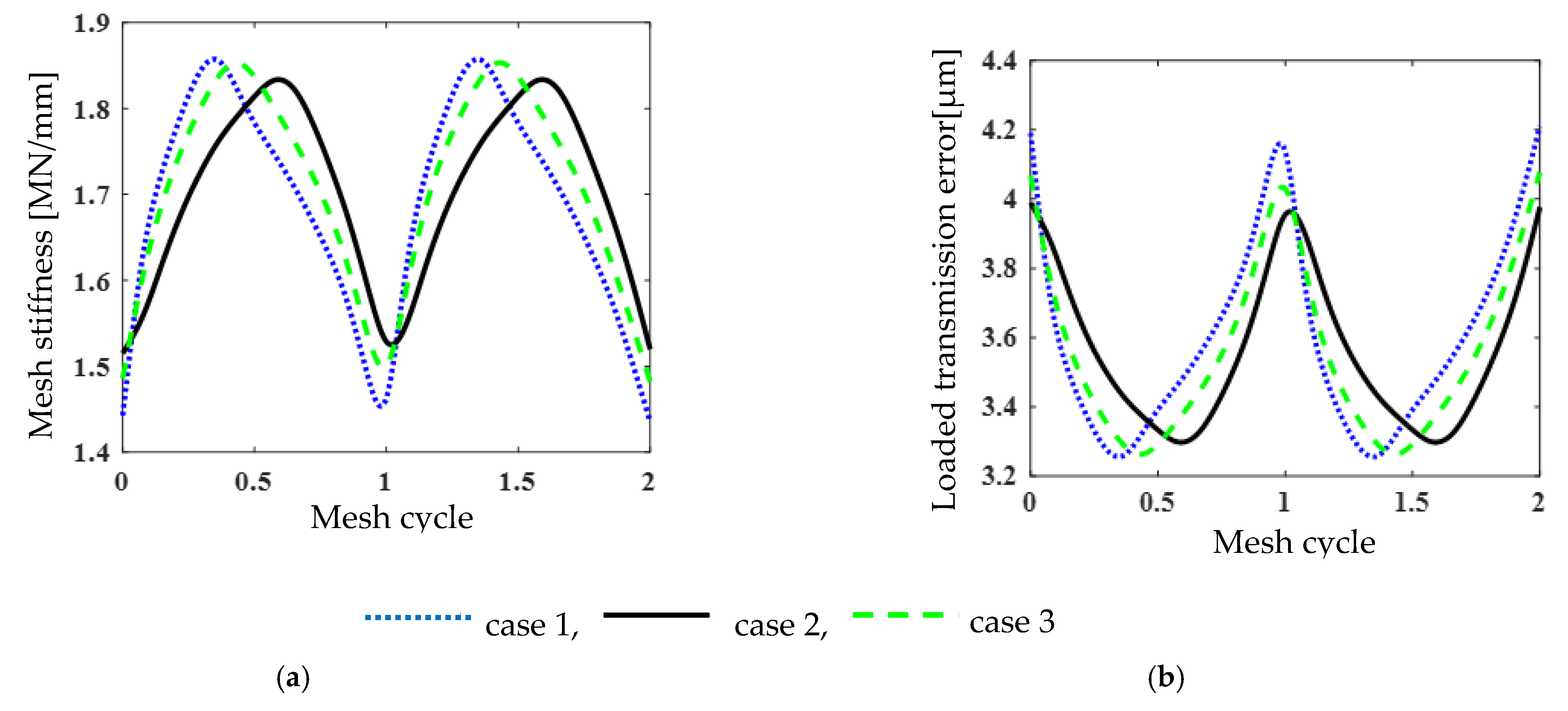
| Peak-to-Peak of Mesh Stiffness [MN/mm] | Peak-to-Peak of LTE [µm] | |
|---|---|---|
| case 1 (axial misalignment) | 0.428 | 0.968 |
| case 2 (radial misalignment) | 0.318 | 0.689 |
| case 3 (radial and axial misalignments) | 0.378 | 0.829 |
| Parameters | Pinion | Gear |
|---|---|---|
| Pitch angle | 30.42° | 59.18° |
| Number of teeth | 19 | 32 |
| Transverse contact ratio | 1.70 | |
| Overlap ratio | 0.13 | |
| Contact ratio | 1.83 | |
| Module (mm) | 2.75 | |
| Backlash (mm) | 0.015 | |
| Nominal torque (N∙m) | 250 | |
| Module of elasticity, E (GPa) | 209 | |
| Poisson ratio, ν | 0.3 | |
| Face width, w (mm) | 12 | |
| Pressure angle, α | 20° | |
| Mean spiral angle | 5° | |
| Damping ratio, ζ [28] | 0.01 | |
Publisher’s Note: MDPI stays neutral with regard to jurisdictional claims in published maps and institutional affiliations. |
© 2021 by the authors. Licensee MDPI, Basel, Switzerland. This article is an open access article distributed under the terms and conditions of the Creative Commons Attribution (CC BY) license (https://creativecommons.org/licenses/by/4.0/).
Share and Cite
Molaie, M.; Samani, F.S.; Pellicano, F. Spiral Bevel Gears Nonlinear Vibration Having Radial and Axial Misalignments Effects. Vibration 2021, 4, 666-678. https://doi.org/10.3390/vibration4030037
Molaie M, Samani FS, Pellicano F. Spiral Bevel Gears Nonlinear Vibration Having Radial and Axial Misalignments Effects. Vibration. 2021; 4(3):666-678. https://doi.org/10.3390/vibration4030037
Chicago/Turabian StyleMolaie, Moslem, Farhad S. Samani, and Francesco Pellicano. 2021. "Spiral Bevel Gears Nonlinear Vibration Having Radial and Axial Misalignments Effects" Vibration 4, no. 3: 666-678. https://doi.org/10.3390/vibration4030037