Design Optimization of Torsional Vibration Absorbers for Heavy-Duty Truck Drivetrain Systems


Department of Mechanics and Maritime Sciences, Chalmers University of Technology, SE-412 96 Göteborg, Sweden
Vibration 2019, 2(3), 240-264; https://doi.org/10.3390/vibration2030015
Submission received: 27 May 2019
/
Revised: 6 July 2019
/
Accepted: 10 July 2019
/
Published: 12 July 2019
Abstract
:In this paper, the feasibility of the application of a dual mass flywheel (DMF) for heavy-duty truck drivetrain systems was studied. The third engine order vibration harmonic was in the focus of analysis as one of the most significant contributions to the oscillatory response in the drivetrain systems of heavy-duty trucks. Global sensitivity analysis (GSA) and Pareto optimization were used for designing torsional vibration absorbers in an operating engine speed range of 600–2000 rpm. The optimization method attempted both to minimize the oscillations of the torque at the transmission input shaft and to maximize the energy efficiency of the vibration absorber. The GSA enabled the appropriate scanning of the domain of design parameters by varying all the parameters at the same time. It provided deep insight into the design process and increased the computational efficiency of the optimization. The results obtained show the following: the solution of the bi-objective optimization problem for torsional vibration absorbers does exist; Pareto fronts were obtained and analyzed for the DMF, presenting a trade-off between the measure of the attenuation of the oscillations of the torque at the transmission input shaft and the measure of the energy efficiency of the absorber; the optimized mass inertia, stiffness and damping parameters of a DMF do exist, providing the best attenuation of the torque oscillations; the performance of a DMF was further enhanced by incorporating a torsional tuned mass damper with appropriate optimized parameters. Finally, the results show evidence of the feasibility of the application of dual mass flywheels in heavy-duty truck drivetrain systems.
1. Introduction
Ground vehicles and many other engineering systems comprise of drivetrains as their important subsystems. The increasing demand for a higher efficiency of engineering systems requires the improvement of existing—and the development of novel—drivetrain functional components. For instance, the automotive industry drives development towards down-sized and down-speeded engines and higher cylinder pressures. This requires advancing the available solutions for noise and vibration attenuation, making the design of efficient torsional vibration absorbers for drivetrain systems of ground vehicles a very important and challenging problem. Academic and industrial research dealing with modeling, simulation and analysis of torsional vibration dynamics, and design and optimization of vibration absorbers for the drivetrains of different engineering systems has already been conducted, see for instance [1,2,3,4,5,6,7,8,9,10,11,12,13,14,15].
One of the well-known designs of vibration absorbers is the dual mass flywheel (DMF). The DMF was a subject for intensive research, see e.g., [6,7,8,9,10,11,12,13,14,15,16,17,18], and has been used in passenger cars since 1985 [19]. The application of a DMF for heavy-duty trucks is also an important topic which still is not sufficiently presented in the literature. The research is ongoing to understand if this concept of the vibration absorber is suitable for the attenuation of torsional vibrations in the drivetrain systems of heavy-duty trucks [9,10,20,21,22].
Another well-known design of vibration absorbers is the tuned mass damper (TMD) [23]. Efficiency, simplicity, and low maintenance cost are some of the most important features of the TMD technology which makes it possible to employ this technique in a variety of engineering applications. Lindell, H., Berbyuk, V., et al. [24] investigated the application of a non-linear tuned vibration absorber to reduce vibration in hand-held impact machines. Detroux et al. [25] considered the performance, robustness, and sensitivity analysis of a non-linear tuned vibration absorber. The effects of different design parameters and force amplitudes on the performance and operation region of the nonlinear tuned vibration absorber were analyzed. In recent years, the attention of researchers has been directed to a new variant of TMD which exploits the beneficial mass amplification of the inerter. The inerter is a device that provides a force proportional to the relative acceleration between its attachment points. The vibration absorber with the inerter shows similarities with the TMD in which the physical mass is partly or entirely replaced by an apparent mass. The inerter-based vibration absorber has been termed the TMD inerter and has shown promising application in the passive vibration control systems of civil engineering structures [26,27,28]. The idea of a TMD was important for developing centrifugal pendulum-based vibration damping systems for automotive industry products [29,30]. In the current study, the idea of a TMD is also utilized in the design optimization of duel mass flywheels.
With the objective to enhance the effectiveness of vibration absorbers, it is important to perform a multi-objective optimization of their structures by considering several the most important quality factors. As a preliminary stage in multi-objective optimization of the design of vibration absorbers, it is recommended to carry out a global sensitivity analysis, enabling appropriate scanning of the domain of design parameters by varying of all the parameters at the same time. This makes it possible to provide deep insight into design process, narrow down the number of inputs and increase the computational efficiency of optimization.
In the current study, the efficiency of global sensitivity analysis and multi-objective optimization is demonstrated for advanced parameter study and the optimization of dual mass flywheels for application in heavy-duty truck drivetrain systems. The focus of the study is motivated by an increasing intention to use of these absorbers not only for the drivetrains of passenger cars but also for application in heavy-duty trucks, which still is not sufficiently discussed in the literature. Firstly, the design optimization problems for vibration absorbers were solved for prescribed values of the engine speed of a heavy-duty truck to understand how much the values of optimized parameters of the absorbers vary for different engine speeds. Then, the problems were considered on a set of input torques describing the excitation of the combustion engine of a heavy-duty truck in an operating speed range up to 2000 rpm. In both cases, the third engine order vibration harmonic was in the focus of analysis as one of the most significant contributions to the oscillatory response. Sensitivity analysis and design optimization problems were considered for a DMF within the range of its structural parameter values, feasible for application in heavy-duty truck drivetrain systems [20,21]. To solve the design optimization problems for vibration absorbers, the computer code SAMO (Sensitivity Analysis and Multi-objective Optimization) was used [31,32,33,34]. The SAMO solves the global sensitivity analysis problem for a multibody system by evaluating the primary and total sensitivity indices of objective functions (quality factors) of the system in question. The multi-objective optimization problem is solved by using a genetic algorithm.
The outline of the paper is as follows: in Section 2 and Section 3, the global sensitivity analysis and Pareto optimization problems were formulated for a generic drivetrain system with a vibration absorber of an arbitrary design. These formulations, together with an outline of the algorithm of the Global sensitivity analysis (GSA), constitute the basis of the methodology for designing optimal vibration absorbers for different drivetrain systems. The results of the global sensitivity analysis and the Pareto optimization of the DMF and the DMF with a TMD with application to heavy-duty truck drivetrain systems are presented in Section 4, Section 5 and Section 6. Mappings between the total sensitivity indices of the quality measures and the design parameters of the vibration absorbers were obtained. Pareto fronts were plotted, reflecting quantitatively and qualitatively the existence of a trade-off between the measure of torsional vibrations attenuation and the measure of energy losses in optimized vibration absorbers. The discussion and the analysis of the obtained results are presented in Section 7. The paper was finalized with conclusions and an outlook of future research.
2. Modelling of a Generic Drivetrain System
The sketch of a generic drivetrain system is depicted in Figure 1. The drivetrain system comprised an engine, a vibration absorber and a load transmission system. The engine generated an input load at the input shaft AB of the vibration absorber. The input load was modelled by the torque , applied at the input shaft of the absorber. Here, is the vector of the parameters of the input load. The vibration absorber consisted of several inertial components, e.g., rotating bodies and , connected by different stiffness and damping components. The load transmission system consisted of the transmission input shaft CD and other machine elements that altogether were used to exploit the output load from vibration absorber for goal-directed operation of an engineering system. As an example, the load transmission system can comprise a clutch, a gearbox, a propeller shaft, a rear axle and the wheels of a ground vehicle. In Figure 1, some elements were drawn coarsely, e.g., the springs, to highlight that they can be part of different designs and with different characteristics, making the drivetrain system a generic one.
The set of operational scenarios (OSs) of a generic drivetrain system was modelled by the torque at the input shaft of the absorber and the torque at the transmission input shaft, denoted by
In Expression (1), is the vector of the parameters of the load transmission system, are the initial and final instants of time and the domains of feasible values of parameters are .
Assuming that a generic drivetrain system is modelled by a multibody system with n degrees of freedom, the equation of the torsional vibration dynamics of the system can be written as
In Equation (2), is the vector of the generalized coordinate, is the mass matrix, is the matrix of all the forces/torques due to stiffness and damping functional components, is the vector-function of the input load, the torque at the transmission input shaft and any other possible external excitations acting on the drivetrain.
The differential Equation (2), together with the initial conditions,
constitute the mathematical model of a generic drivetrain system.
The equations of the motion of a generic drivetrain system can also be written in state-space representation by introducing the state-space variables
In this case, the model is presented by the first-order differential equations with corresponding initial conditions
If a feasible operation scenario
is given as input, then by choosing an appropriate mathematical model for a generic drivetrain system, the torsional vibration dynamics can be determined for all by solving the initial value problem, i.e., Equation (2) or Equation (5), together with corresponding initial conditions.
3. Sensitivity Analysis and Pareto Optimization
A sensitivity analysis of an engineering system with respect to varying parameter can be carried out either locally or globally. In the local sensitivity analysis, the effects of design input on the system response was approximated as the partial derivative of an objective function used as a measure of the system’s response with respect to design parameter , which was taken around a fixed point . Such an approach only considered the variation of an objective function with respect to one design parameter at a time. Furthermore, the domain of the input design variables might not have been appropriately scanned using the local methods.
The global sensitivity analysis is one of the most prominent approaches in the design of engineering systems that can provide informative insight into the design process. To determine the global sensitivity indices, multilayer integrals must be evaluated. This process demands a heavy computational effort. Zhang and Pandey [35] proposed the multiplicative dimensional reduction method, which can approximate global sensitivity indices in an efficient and accurate manner. The proposed method is briefly described in the following paragraph.
An objective function can be expressed as a function of a set of m independent random variables, i.e., design parameters , through respective deterministic functional relationship . It is proposed to approximate the function as
where, is a constant, and denotes the function value for the case that all inputs except are fixed at their respective cut point coordinates, . Expression (7) is able to approximate the function with a satisfactory level of accuracy and is particularly useful for approximating the integrals required for calculating sensitivity indices [36,37].
Using this approach, primary and higher order sensitivity indices can be approximated as
The coefficients , and are defined as the mean and the mean square of the kth univariate function, respectively, and are represented as
Here N is the total number of integration points, , and are the lth Gaussian integration abscissas, and corresponding weight, respectively.
Finally, the total sensitivity index, corresponding to the parameter , can be expressed as
The accuracy of the introduced sensitivity indices depends on the number of integration points and a convergence study should be accomplished to yield the suitable number of integration points [35,37]. Using computer code SAMO, it was found that for the global sensitivity analysis of the generic drivetrain system in question, the suitable number of integration points was N = 10. It should be noted that the total number of objective function evaluations required for calculating the sensitivity indices using this method is only m × N, where m is the number of design parameters.
To accomplish a sensitivity analysis of a system output, a suitable cut point, together with a probability distribution, must be chosen. Equations (8)–(10) were then utilized to attain sensitivity indices.
Global Sensitivity Analysis and Pareto Optimization Problem Formulations
The following problem of the global sensitivity analysis for a generic drivetrain system is formulated.
Problem GSA. Let be the vector of the design parameters of a vibration absorber and the functionals
were chosen to measure the quality of the performance of the absorber in the drivetrain system in question. It was required for a given feasible operational Scenario (6) and by using the Equation (10) to determine the total sensitivity indices
of the Functionals (11) for all the random varying design parameters , subject to differential Equation (2), initial Conditions (3) and the restriction
The solution of the problem GSA provided mapping between the values of the total sensitivity indices (12) of the objective Functions (11) and the design parameters of the vibration absorber. After the solution of the problem GSA, the vector of the most important design parameters
as well as the most sensitive functionals , were identified. Then, the following multi-objective optimization problem for the vibration absorber in question were stated.
Pareto Optimization Problem. For given feasible operational Scenario (6), it is required to determine the vector of the design parameters
and the torsional vibration dynamics that altogether satisfy the system of variational equations
subject to differential Constraints (2), initial Conditions (3) and Restriction (14).
4. A Drivetrain System Equipped with a Dual Mass Flywheel
Consider a vibration absorber with two rigid bodies called the primary flywheel, (PFW), and the secondary flywheel, (SFW), (see Figure 2). The wheels are connected by massless linear torsional spring and a massless linear torsional viscous damper. The engine output shaft AB and the transmission input shaft CD are assumed to be rigid and connected rigidly to the PFW and to the SFW, respectively. The torque rotates the primary flywheel about the shaft AB.
In Figure 2, are the absolute angles of rotation of the PFW and the SFW, respectively; are the torsional moments of inertia of the PFW and the SFW, respectively; are the coefficients of torsional stiffness and torsional damping.
The friction torque in the stiffness-damping interface of a DMF is expressed as
The equations of the torsional vibration dynamics of the drivetrain system equipped with a DMF are
These equations, together with the initial conditions
constitute the mathematical model of the system.
4.1. Global Sensitivity Analysis of a Drivetrain System Equipped with a DMF
The set of operational Scenarios (1) of the drivetrain system is defined by the expressions
The input load is modelled by the constant torque plus the harmonic function. Here, is the engine order vibration frequency, that is times the angular velocity , and is the engine speed in rpm. The set of input Loads (21) has the following vector of parameters
The torque at the transmission input shaft is modelled by Expression (22) and includes the following vector of parameters
Here, are the equivalent torsional stiffness and damping coefficients of the load transmission system, are the absolute angle of rotation and the angular velocity of the transmission input shaft. The parameters defined the vibration at the transmission input shaft.
Consider the vector
and the following functionals
as the vector of design parameters and the quality measures of the performance of the drivetrain system equipped with a DMF.
The Functionals (26) and (27) measure standard deviation (std) and the peak-to-peak value (peak_peak) of the torque at the transmission input shaft , the friction torque in the stiffness-damping interface, and the torsional vibration of the DMF.
The global sensitivity analysis problem (problem GSA), formulated in Chapter 3, was solved for the drivetrain system equipped with a DMF by using the differential Equations of motion (18) and (19), the initial Conditions (20), the vector of the design Parameters (25) and the Functionals (26) and (27). The feasible operation Scenario (6) was given by the torques and that are determined by Expressions (21)–(24).
The third engine order vibration harmonic was in the focus of the analysis as one of the most significant contributions to the oscillatory response [21], i.e., the engine order vibration frequency n0 was chosen to be equal to 3 in all simulations. The rest values of the parameters for the torque were the following: the mean value of the engine input torque Tm = 300 Nm; the amplitude of the engine torque harmonic excitation ae = 500 Nm; the phase angle of the harmonic excitation = 0; and the engine speed ne was chosen in the range of 800–2000 rpm. The values for the parameters of the torque at the transmission input shaft are: kv = 100,000 Nm/rad, cv = 0.1 Nms/rad, ag = = 0, and .
The input torque values for ne = 800 rpm and 1400 rpm are depicted in Figure 3.
The results of the GSA of the drivetrain system, with respect to the variation of the design Parameters (25), were obtained for the different prescribed engine speeds by using the computer code SAMO with the settings provided in Table 1.
In Table 1, the initial values of the design parameters of the DMF were chosen to be feasible for application in heavy-duty truck drivetrain systems. The analysis was performed with a normal distribution of the varying parameters and a coefficient of variation equal to 0.1. The solutions of the global sensitivity problem for prescribed engine speeds ne = 800 rpm, 1200 rpm, and 1400 rpm are depicted in Figure 4, Figure 5 and Figure 6. The solutions are presented by means of mappings between the design parameters and the values of the total sensitivity indices of the objective Functions (26) and (27).
4.2. Pareto Optimization of a Drivetrain System Equipped with a DMF
The optimization problem formulated in Section 3 was considered for the drivetrain system equipped with a DMF. The problem is stated as follows: for the prescribed engine speed ne, it is required to determine the vector of the design parameters of the DMF
and the torsional vibration dynamics that satisfy the variational equations
subject to the differential Equations (18) and (19), the initial Conditions (20) and the restrictions on the design parameters provided by the lower and upper bounds in Table 1.
This problem was solved by computer code SAMO for the same operational scenarios as the problem of the global sensitivity analysis. The corresponding system of the differential equations was solved by using a MATLAB® subroutine ode45 with absolute and relative tolerances equal to 1e-5. The setting of the genetic algorithm was as follows: population size—100; number of generations—100; elite count—4; and Pareto fraction—1. In Table 2 and in Figure 7 and Figure 8, some of the results of the solution of the Pareto optimization problem for engine speeds ne = 800–2000 rpm are shown.
The Pareto fronts, i.e., the best trade-off relationships between and , obtained for several prescribed engine speeds, are shown in Figure 7.
Every point of the Pareto front with coordinates (, ) corresponds the set of values of the design parameters of the DMF. The values of the design parameters of the DMF that minimized std(Tg[q(t), d]) are provided in Table 2. These values correspond to the highest points of the respective Pareto fronts. An analysis of Table 2 showed that in comparison to the nominal values of the design parameters of the DMF (the data in the first row of Table 1), the Pareto optimized designs of the dual mass flywheels were characterized by damping coefficients about three times higher and significant variation in mass inertia parameters (e.g., moments of inertia of the primary flywheel—in the case of engine speed ne = 800 rpm—up to twice higher than its nominal value). This can significantly restrict the implementation.
In the last column of Table 2, the values of std(Tg[q(t), d]), evaluated for the DMF with the nominal values of its design parameters, are presented. A comparison with the last two columns of Table 2 reveals that the Pareto optimized design parameters of the DMF make it possible to decrease significantly (up to three times) the standard deviation of the torque at the transmission input shaft.
As Figure 7 shows, there exist many optimized solutions for the design of the DMF that guarantee the highest attenuation of oscillations in the torque at the transmission input shaft for the engine speed in the range of 1400–2000 rpm with the value of std(Tg[q(t), d]) lower than 20 Nm, (see Pareto points in the rectangular area in Figure 7).
In Figure 8, the time history of the torques at the transmission input shaft of the drivetrain system equipped with nominal DMF (dashed curves) and for the system with an optimized DMF (solid curves) are shown, illustrating the significant attenuation of the torques’ oscillation by the obtained Pareto-optimized DMF.
5. A Drivetrain System with a Dual Mass Flywheel with a Tuned Mass Damper
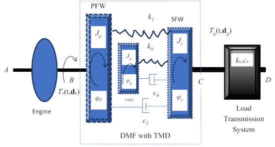
The vibration absorber comprised a DMF and an additional rigid body connected to the secondary flywheel by a linear spring and a linear dashpot. This body was termed the tuned mass damper. The sketch of a drivetrain system equipped with a DMF with a TMD is depicted in Figure 9.
The vibration dynamics of the considered drivetrain system are described by the equations
In Equations (31)–(33), are the moment of inertia, the coefficients of stiffness and the viscous damping of the TMD, respectively; is the absolute angle of rotation of the TMD. The Equations (31)–(33), together with the initial conditions
constitute the mathematical model of the drivetrain system with a DMF with a TMD.
5.1. Global Sensitivity Analysis of a Drivetrain System with a DMF with a Tuned Mass Damper
The following problem for the drivetrain system equipped with a DMF with a TMD is considered. It is required to determine the total sensitivity indices (10) for the objective functions
subject to the equations of the torsional vibration Dynamics (31)–(33), the initial Conditions (34) and the variation of the design parameters
with the restrictions given by the lower and upper bounds in Table 3.
In Expressions (35) and (36), the friction torque is defined in the form
The feasible operational scenario is determined by the engine torque and the torque at the transmission input shaft given by Formulaes (21) and (22) with the same values of the Parameters (23) and (24) used in a sensitivity analysis of the DMF without a tuned mass damper.
The results of the sensitivity analysis of the drivetrain system equipped with a DMF with a TMD for engine speeds ne = 800 rpm and 1200 rpm are depicted in Figure 10 and Figure 11. The solutions were presented by means of mappings between the design parameters and the values of the total sensitivity indices of objective Functions (35) and (36).
5.2. Pareto Optimization of a Drivetrain System Equipped with a DMF with a Tuned Mass Damper
The optimization problem formulated in Chapter 3 was solved for a drivetrain system equipped with a DMF with a TMD. It is now required to determine the vector of the design parameters
and the torsional vibration dynamics that altogether satisfy the system of variational Equations (29) and (30), subject to the equations of the vibration Dynamics (31)–(33), the initial Conditions (34) and the restrictions on the design parameters provided by the lower and upper bounds in Table 3.
The problem was solved for the same operational scenarios as the Pareto optimization problem of the DMF without a tuned mass damper. The obtained results for several prescribed engine speeds are presented in Figure 12 and Figure 13 and in Table 4. The Pareto fronts in the case of optimization of the DMF with a TMD are depicted by star-curves in Figure 12. For comparison, this figure also comprises the Pareto fronts obtained in Chapter 4, depicted by dotted curves.
For the same prescribed engine speeds in the case of optimization of the DMF without a TMD. An analysis of Figure 12 clear indicates that many designs of vibration absorbers comprise an optimized DMF with a TMD that can significantly enhance attenuation of oscillation of the torque at the transmission input shaft in comparison to the performance of the vibration absorbers comprising an optimized DMF without TMD. As evidence of the above statement, there are many Pareto star-points without dotted points in the ellipse area of Figure 12. An analysis of Figure 12 also shows the existence of a lot of designs of optimized DMF with a TMD when the incorporation of the TMD does not significantly enhance the performance of the vibration absorbers in comparison to the optimized DMF without a TMD, (see the closely distributed Pareto star-points and dotted-points in the rectangle in Figure 12).
The values of the design parameters of the DMF with a TMD that minimize the standard deviation of the torque at the transmission shaft, std(Tg[q(t), d]) are provided in Table 4. The values of the design parameters of the DMF with a TMD correspond to the highest points of the respective Pareto fronts depicted in Figure 12.
A detailed comparative analysis of Figure 7 and Figure 12 and the minimum values of std(Tg[q(t), d]) presented in Table 2 and Table 4 reveals that the incorporation of the TMD into the DMF makes it possible to decrease the standard deviation of the torque at the transmission input shaft (by up to two times). Figure 13 presents the time history of the torques at the transmission input shaft, illustrating how much the TMD with the optimized design parameters can enhance the attenuation of the torques’ oscillations in comparison to the optimized DMF without a TMD.
6. Design Optimization of a DMF and a DMF with a TMD in the Operating Engine Speed Range
The results of the Pareto optimization of the vibration absorbers presented in Section 4 and Section 5 provides insight into the sensitivity of the vibration dynamics and especially the oscillation of the torque at the transmission input shaft with respect to variation of the design parameters of a DMF and a TMD in the case of the prescribed engine speed. An analysis of the data in Table 2 and Table 4 reveals that the optimized parameters of the vibration absorber significantly varied with engine speed. It is still unknown how these parameters could be varied easily and efficiently at different engine speeds in real applications. One approach to change the damping in a DMF using magnetorheological fluid with a control of the magnetic field strength is proposed in [38].
In Figure 14, the engine speed history of the standard deviation of the torques at the transmission input shaft, std(Tg[q(t), d]) is depicted: the black curve represents the nominal values of the DMF design Parameters (40), the red curve shows the DMF with the optimized design Parameters (41) for engine speed ne = 800 rpm, the green curve shows the DMF with the optimized design Parameters (42) for engine speed ne = 1600 rpm, and the blue curve represents the case of engine speed ne = 1800 rpm with optimized design Parameters (43).
Figure 14 shows that in comparison to the DMF with the nominal values of the design parameters, the DMF optimized for the prescribed engine speed ne = 800 rpm attenuated oscillation at the transmission input for the operating speed range . The dual mass flywheels optimized for the prescribed engine speeds 1600 rpm and 1800 rpm did not reduce the high resonance peak of oscillation of the torque at the transmission input shaft. It should also be mentioned that the obtained vectors of optimized design Parameters (41)–(43) were characterized by much higher moments of inertia of the flywheels in comparison to their nominal values (40). This is why it is important to consider the design optimization problems of vibration absorbers in the engine operating speed range and to impose sharper restrictions on mass inertial characteristics of the flywheels suitable for implementation in heavy-duty trucks powertrains.
Below, a multi-objective optimization methodology is applied for designing the vibration absorbers for the best attenuation of oscillations of the torques at the transmission input shaft in the engine operating speed range up to 2000 rpm. With the intention to take care both with the resonances of the oscillations of the torque at the transmission input shaft as well as to enhance the vibration attenuation in the operating engine speed range, it is proposed to use the following functionals for the optimization of the design of vibration absorbers
The Functionals (44) characterize the energy of the oscillations of the torque at the transmission input shaft and the energy dissipating in a DMF in the operating engine speed range . It is believed that by minimizing these functionals at the same time, the obtained design parameters increase the energy efficiency of a vibration absorber.
Using the Functionals (44), the solution of the global sensitivity analysis problem of a drivetrain system equipped with DMF (problem GSA) was obtained in the operating speed range using computer code SAMO with the settings provided in Table 5.
The solution is presented in Figure 15 by mapping the design parameters and the values of the total sensitivity indices of the objective Functions (44).
Then, the Pareto optimization problem was solved in the operating engine speed range by determining the vector of the design parameters of the DMF and the torsional vibration dynamics that satisfied the following variational equations
subject to the differential Equations (18) and (19), the initial Conditions (20) and the restrictions on the design parameters provided in Table 5.
The obtained values of the design parameters of the DMF which minimize the objective function are
The values of the design parameters which minimize the objective function are
In Figure 16, the standard deviation of the torques at the transmission input shaft as a function of the engine speed for the DMF with nominal design Parameters (40) (black curve), and for the DMF with optimized design parameters defined by the Vector (47) (blue curve), are depicted.
The solutions of the global sensitivity and Pareto optimization problems of a drivetrain system with the DMF with a TMD in the operating speed range were also obtained by using objective Functions (44) with the settings provided in Table 6. The mapping between the design parameters and the values of the total sensitivity indices of the Functionals (44) is presented in Figure 17.
Then, the Pareto optimization problem for the DMF with a TMD was solved by determining the vector of the design parameters and the torsional vibration dynamics that satisfied the variational Equations (45) and (46) in the operating speed range , subject to the differential Equations (31)–(33), the initial Conditions (34) and the restrictions on the design parameters provided in Table 6. The obtained Pareto front is depicted in Figure 18.
The design parameters which minimize the objective function are
As it follows from (49), the optimized stiffness of the TMD was approximately the same as the stiffness of the DMF. The obtained value of the parameter shows that the total torsional moment of inertia of the novel vibration absorber, i.e., the DMF with a TMD, increased by less than 9%. This is good evidence of the feasibility of incorporating a TMD into a DMF.
The standard deviation of the torque at the transmission input shaft as a function of the engine speed in the range for the DMF with a TMD with the obtained optimized design parameters defined by (49) is depicted in Figure 16 (red curve). An analysis of Figure 16 reveals that the incorporation of the TMD into the DMF can enhance the attenuation of the oscillation of the torque at the transmission input shaft in comparison to the optimized DMF. It should also be noted that the values of the design Parameters (47) and (48) are very close. This also leads to the sub-optimality of the obtained design of the vibration absorber with respect to minimizing the dissipation of the energy due to friction in the DMF.
7. Results and Discussion
The application of the global sensitivity analysis and the Pareto optimization provide deep insight into torsional vibration dynamics of a generic drivetrain system with vibration absorbers. Two concepts of vibration absorbers were studied with the aim of analyzing the feasibility of their application in heavy-duty truck drivetrain systems: a DMF and a DMF with a torsional tuned mass damper. Several measures were considered for the vibration analysis and the design optimization of a drivetrain system with focus on the evaluation of the absorbers with respect to vibration attenuation and energy efficiency. The torque at the transmission input shaft, , and the friction torque,, at the DMF were analyzed. The standard deviation, peak-to-peak and the integrals of the standard deviations of the torques calculated along the engine speed interval , were used for estimating the vibration attenuation and the energy efficiency of the torsional vibration absorbers.
Here, a first detailed analysis of the results obtained in Section 4 and Section 5 for certain prescribed engine speeds of a heavy-duty truck is presented. Then, the outcome of the vibration absorbers design optimization on a set of input torques describing the excitation of a combustion engine in the operating engine speed range up to 2000 rpm is analyzed. In both cases the third engine order vibration harmonic is in focus as one of the most significant contributions to the oscillatory response.
The results of the global sensitivity analysis of the drivetrain system with respect to the design parameters of the DMF and the DMF with a TMD, presented in Figure 4, Figure 5, Figure 6, Figure 10, Figure 11, Figure 15 and Figure 17, make it possible to conclude the following.
- All the design parameters, significantly affected the level of attenuation of the oscillation of the torque at the transmission input shaft, the friction torque, and the torsional vibration of a DMF.
- The stiffness, i.e., the parameter , most affected the peak-to-peak and the standard deviation of the torsional vibration in the drivetrain system equipped with a DMF, (see sensitivity indices of the objective functionals and in Figure 4, Figure 5 and Figure 6). The torsional stiffness also significantly affected the measures of the torque at the transmission input shaft , as well as the friction torque of the DMF.
- The numerical simulations show that the damping, , affected mostly the friction torque .
- The moment of inertia of the primary flywheel, , had the largest effect on the measures of the torque at the transmission input shaft as well as on the measures of the friction torque for engine speed ne = 800 rpm, (see Figure 4), and its effect decayed with the increasing engine speed.
- Figure 10 and Figure 11 present mappings between the design parameters and total sensitivity indices of the measures of the vibration Dynamics (35) and (36) of the drivetrain system equipped with a DMF with a tuned mass damper. An analysis shows that the moment of inertia, as well as the stiffness coefficients most affected the vibration attenuation and the energy efficiency of the design of the vibration absorber. The stiffness coefficient and the moment of inertia of the tuned mass damper had the largest effect on the considered measures for low engine speed.
- In the case of the design of the vibration absorbers in the operating engine speed range 600–2000 rpm for heavy-duty truck drivetrain systems, the propose objective Functions (44) were the most sensitive with respect to the stiffness and the moment of inertia of the primary flywheel of the DMF, as well as with respect to the stiffness and the moment of inertia of the tuned mass damper (see Figure 15 and Figure 17).
An analysis of the results of the Pareto optimization of the drivetrain system equipped with a DMF and the system with a DMF with a tuned mass damper makes it possible to conclude the following:
- As shown in the last two columns of Table 2, in the case of the design optimization of the vibration absorber for the prescribed engine speed, the standard deviation of the torque at the transmission input shaft can be decreased significantly (up to three times) by choosing appropriate values of the design parameters of the DMF in comparison to the standard deviation of the torque obtained for the nominal values of design Parameters (40).
- With an increasing engine speed, the attenuation of oscillations of the torque at the transmission input shaft required a higher inertia moment of the primary flywheel and a lower inertial moment of the secondary flywheel (see columns 4 and 5 in Table 2). Therefore, to guarantee an acceptable level of torque oscillations for the whole range of engine speeds, an appropriate trade-off between the values of the moments of inertia of the primary and the secondary flywheels must be chosen.
- The Pareto optimization results, obtained for the prescribed values of engine speed in the range 800–2000 rpm, show that the incorporation of the tuned mass damper into the DMF made it possible to decrease significantly (up to two times) the standard deviation of the torque at the transmission input shaft in comparison to the case of the optimized DMF without a tuned mass damper (see column 6 in Table 2 and the last column in Table 4).
The design optimization of vibration absorbers for the prescribed engine speed is valuable and provides deep insight into the advanced analysis of a drivetrain system performance for different structural design parameters. However, this study shows that the vibration absorber optimized for the prescribed engine speed can be far from being the optimal one in the operating speed range (see the blue and green curves in Figure 14). Chapter 6 presents the results of the optimization of the vibration absorbers for the best attenuation of oscillations of the torque at the transmission input shaft for heavy-duty truck drivetrain systems in the operating engine speed range up to 2000 rpm. An analysis of these results makes it possible to conclude the following:
- The choice of objective functions is an important step in the design optimization of vibration absorbers for heavy-duty truck drivetrain systems. The proposed objective Functions (44) seemed to be suitable for optimizing a DMF and a DMF with a tuned mass damper in the operating engine speed range. Using these objective functions, it was shown that for the drivetrain system equipped with DMF and with the DMF with a TMD, there exists a trade-off between the vibration attenuation and the energy efficiency (see Figure 18).
- An evaluation of the objective function for the nominal and optimized values of the design parameters of a DMF (Parameters (40) and (47)), makes it possible to compare quantitatively the obtained engine speed history of the standard deviation of the torques at the transmission input shaft for a nominal and an optimized DMF. The results show that the efficiency of the attenuation of the oscillations of the torque at the transmission input shaft increased by up to 40% in comparison to the performance of the DMF with nominal design parameters.
- An analysis of the obtained solution of the Pareto optimization problem in the operating engine speed range 600–2000 rpm for the DMF with a TMD reveals that within the frame of considered assumptions, the incorporation of a TMD into a DMF enhanced the performance of the vibration absorber in comparison to the optimized DMF without a TMD (see blue and red curves in Figure 16).
8. Conclusions and Outlook
Finally, the following concluding remarks can be drawn:
- There existed a clear trade-off between the measure of the oscillations attenuation of the torque at the transmission input shaft and the measure of the energy efficiency in the design of torsional vibration absorbers for heavy-duty truck drivetrain systems both in the case of a DMF and in the case of a DMF with a tuned mass damper.
- For a heavy-duty truck drivetrain system equipped with a DMF, the optimized mass inertia, stiffness, and damping parameters provided the best attenuation of oscillations of the torque at the transmission input shaft in the operating engine speed range 600–2000 rpm when the third engine order vibration harmonic was in focus.
- The incorporation of a torsional tuned mass damper into a DMF with the appropriate optimization of design parameters can significantly enhance the performance of the combined vibration absorber. For instance, for the operating engine speed range 800–1200rpm, the utilization of the TMD in the DMF decreased up to two times the standard deviation of the torque at the transmission input shaft in comparison to the standard deviation of the torque in the case of the optimized DMF without a tuned mass damper.
- The global sensitivity analysis and Pareto optimization were proven to be efficient for advanced analysis and design of torsional vibration absorbers for drivetrain systems. The results obtained are evidence of the feasibility of the application of dual mass flywheels in heavy-duty truck drivetrain systems.
A study of the limiting possibilities of vibration absorption in drivetrain systems using the same concepts as the vibration absorbers within the frame of non-linear models could be the focus of future research [10,18,30]. Verification and validation of the results obtained using new methods for optimizing the parameters of torsional vibration dampers [15,22], a complete model of a drivetrain system of a heavy-duty truck [21], as well as experimental data are also important next steps of the study [10,39].
Funding
This research was partially funded by the Swedish Energy Agency, project No. 42100-1.
Acknowledgments
Lina Wramner and Anders Hedman (Volvo Group Trucks Technology) and Håkan Johansson (CHALMERS) are acknowledged for their useful comments and suggestions. The author is grateful to reviewers for their critical and very valuable comments.
Conflicts of Interest
The author declares no conflict of interest.
References
- Haddow, A.; Shaw, S. Centrifugal Pendulum Vibration Absorbers: An Experimental and Theoretical Investigation. Nonlinear Dyn. 2003, 34, 293–307. [Google Scholar] [CrossRef]
- Wellmann, T.; Govindswamy, K.; Braun, E.; Wolff, K. Aspects of Driveline Integration for Optimized Vehicle NVH Characteristics. In Proceedings of the Noise and Vibration Conference and Exhibition, St. Charles, IL, USA, 15–17 May 2007. SAE Technical Paper. [Google Scholar]
- Park, T.; Song, J.; Jang, J.; Joo, I. Dynamic Analysis of Damper System in Torque Converter. In Proceedings of the Asia Pacific Automotive Engineering Conference, California, CA, USA, 5–8 August 2007; SAE Technical Paper. pp. 1–7. [Google Scholar]
- Struggl, S.; Berbyuk, V.; Johansson, H. Review on wind turbines with focus on drive train system dynamics. Wind Energy 2015, 18, 567–590. [Google Scholar] [CrossRef]
- Habib, G.; Kerschen, G. A principle of similarity for nonlinear vibration absorbers. In Proceedings of the ASME 2015 International Design Engineering Technical Conferences and Computers and Information in Engineering Conference, IDETC/CIE 2015, Boston, MA, USA, 2–5 August 2015. [Google Scholar]
- Chaithanya, D.; Narayanasamy, A. Engine Flywheel Failure Avoidance through CAE Optimization. In Proceedings of the WCXTM 17: SAE World Congress Experience, Detroit, ML, USA, 4–6 April 2017; SAE Technical Paper. pp. 1–7. [Google Scholar]
- Gupta, K.; Choudhary, A.; Bidre, R. NVH Performance Improvement Study Using a Dual Mass Flywheel (DMF), Inertia Ring Type Tuned Torsional Vibration Damper (TVD) and Single Mass Flywheel (SMF) in a Front Engine and Rear Wheel Driveline Architecture. In Proceedings of the Noise and Vibration Conference and Exhibition, Monroe Village, NW, USA, 12–15 June 2017; SAE Technical Paper. pp. 1–8. [Google Scholar]
- Mall, P.; Fidlin, A.; Krüger, A.; Groß, H. Simulation based optimization of torsional vibration dampers in automotive powertrains. Mech. Mach. Theory 2017, 115, 244–266. [Google Scholar] [CrossRef]
- Wramner, L. Torsional vibrations in truck powertraines with dual mass flywheel having piecewise linear stiffness. In Proceedings of the 9th European Nonlinear Dynamics Conference, ENOC 2017, Budapest, Hungary, 25–30 June 2017; pp. 1–10. [Google Scholar]
- Wramner, L.; Berbyuk, V.; Johansson, H. Vibration dynamics in non-linear dual mass flywheels for heavy-duty trucks. In Proceedings of the 28th edition of the Biennial ISMA conference on Noise and Vibration Engineering, Leuven, Belgium, 17–19 September 2018; pp. 1863–1876. [Google Scholar]
- Haris, A.; Motato, E.; Theodossiades, S.; Rahnejat, H.; Kelly, P.; Vakakis, A.; Bergman, L.; McFarland, D.M. A study on torsional vibration attenuation in automotive drivetrains using absorbers with smooth and non-smooth nonlinearities. Appl. Math. Modelling 2017, 46, 674–690. [Google Scholar] [CrossRef]
- Shi, C.; Parker, R.G.; Shaw, S.W. Tuning of Centrifugal Pendulum Vibration Absorbers for Translational and Rotational Vibration Reduction. Mech. Mach. Theory 2013, 66, 56–65. [Google Scholar] [CrossRef]
- Shi, C.; Shaw, S.W.; Parker, R.G. Vibration Reduction in a Tilting Rotor Using Centrifugal Pendulum Vibration Absorbers. J. Sound Vib. 2016, 385, 55–68. [Google Scholar] [CrossRef]
- Keeney, C.S.; Shih, S. Prediction and Control of Heavy Duty Powertrain Torsional Vibration. J. Commer. Vehicles 1992, 101, 805–814. [Google Scholar]
- Tan, X.; Hua, L.; Lu, C.; Yang, C.; Wang, Y.; Wang, S. A new method for optimizing the parameters of torsional vibration dampers. J. Vibroeng. 2017, 19, 4155–4171. [Google Scholar]
- Song, L.Q.; Zeng, L.P.; Zhang, S.P.; Zhou, J.D.; Niu, H.E. Design and analysis of a dual mass flywheel with continuously variable stiffness based on compensation principle. Mech. Mach. Theory 2014, 79, 124–140. [Google Scholar] [CrossRef]
- Chen, L.; Zeng, R.; Jiang, Z. Nonlinear dynamical model of an automotive dual mass flywheel. Adv. Mech. Eng. 2015, 7, 1–11. [Google Scholar] [CrossRef]
- Fidlin, A.; Mall, P. On the effect of the distributed friction in the arc spring on the dynamic behavior of the automotive transmission. In Proceedings of the International Conference on Engineering Vibrations, ICoEV, Ljubljana, Slovenia, 7–10 September 2015; pp. 1099–1108. [Google Scholar]
- Faust, H. Powertrain systems of the future—engine, transmission and damper systems for downspeeding, downsizing and cylinder deactivation. In Proceedings of the Schaeffler Symposium, Baden-Baden, Germany, 3–4 April 2014; pp. 24–41. [Google Scholar]
- Wramner, L. Dual Mass Flywheels in Truck Powertrains: Modelling, Simulations and Validation. Licentiate Thesis, Department of Mechanics and Maritime Sciences, Chalmers University of Technology, Göteborg, Sweden, December 2018; p. 32. [Google Scholar]
- Wramner, L. Torsional vibrations in heavy-duty truck powertrains with dual mass flywheels. Int. J. of Heavy Vehicle Systems 2019. Submitted. [Google Scholar]
- Karimaei, H.; Mehrgou, M.; Chamani, H.R. Optimisation of torsional vibration system for a heavy-duty inline six-cylinder diesel engine. Proc. Inst. Mech. Eng. Part K J. Multi-body Dyn. 2019, 1–15. [Google Scholar] [CrossRef]
- Den Hartog, J.P. Mechanical Vibrations; Dover Publication, Inc.: New York, NY, USA, 1985. [Google Scholar]
- Lindell, H.; Berbyuk, V.; Josefsson, M.; Grétarsson, S. Nonlinear dynamic absorber for reduce vibration in hand-held impact machines. In Proceedings of the International Conference on Engineering Vibration, Ljubljana, Slovenia, 7–10 September 2015; pp. 1530–1539. [Google Scholar]
- Detroux, T.; Habib, G.; Masset, L.; Kerschen, G. Performance, robustness and sensitivity analysis of the nonlinear tuned vibration absorber. Mech. Syst. Signal Process. 2015, 60–61, 799–809. [Google Scholar] [CrossRef]
- De Domenico, D.; Ricciardi, G. An enhanced base isolation system equipped with optimal tuned mass damper inerter (TMDI). Earthquake Eng. Struct. Dyn. 2018, 47, 1169–1192. [Google Scholar] [CrossRef]
- De Domenico, D.; Ricciardi, G. Optimal design and seismic performance of tuned mass damper inerter (TMDI) for structures with nonlinear base isolation systems. Earthquake Eng. Struct. Dyn. 2018, 47, 2539–2560. [Google Scholar]
- De Domenico, D.; Impollonia, N.; Ricciardi, G. Soil-dependent optimum design of a new passive vibration control system combining seismic base isolation with tuned inerter damper. Soil Dyn. Earthquake Eng. 2018, 105, 37–53. [Google Scholar] [CrossRef]
- Fidlin, A.; Seebacher, R. DMF simulation techniques—Finding the needle in the haystack. In Proceedings of the LuK Symposium, Baden, Austria, 4–5 May 2006; pp. 55–70. [Google Scholar]
- Shaw, S. Designing Nonlinear Torsional Vibration Absorbers. In Exploiting Nonlinear Behavior in Structural Dynamics; Wagg, D., Virgin, L., Eds.; Springer: Wien, Austria, 2012; pp. 135–169. [Google Scholar]
- Mousavi Bideleh, S.M.; Berbyuk, V. A Computer Code for Sensitivity Analysis and Multiobjective Optimization: SAMO Tutorial; Department of Mechanics and Maritime Sciences, Chalmers University of Technology: Gothenburg, Sweden, 2017; Report No. 1; pp. 1–45. [Google Scholar]
- Mousavi Bideleh, S.M.; Berbyuk, V. Global sensitivity analysis of bogie dynamics with respect to suspension components. Multibody Syst. Dyn. 2016, 37, 145–174. [Google Scholar] [CrossRef]
- Mousavi Bideleh, S.M.; Berbyuk, V. Multiobjective optimisation of bogie suspension to boost speed on curves. Vehicle Syst. Dyn. 2016, 54, 58–85. [Google Scholar] [CrossRef]
- Mousavi Bideleh, S.M.; Berbyuk, V. Pareto Optimization of a Nonlinear Tuned Mass Damper to Control Vibrations in Hand Held Impact Machines. In Nonlinear Dynamics, Volume 1. Conference Proceedings of the Society for Experimental Mechanics Series; Kerschen, G., Ed.; Springer: Cham, Germany, 2018; pp. 27–44. [Google Scholar]
- Zhang, X.; Pandey, M.D. An effective approximation for variance-based global sensitivity analysis. Reliability Eng. Syst. Safety 2014, 121, 164–174. [Google Scholar] [CrossRef]
- Rabitz, H.; Alis, Ö. General foundations of high-dimensional model representations. J. Math. Chem. 1999, 25, 197–233. [Google Scholar] [CrossRef]
- Zhang, X.; Pandey, M.D. Structural reliability analysis based on the concepts of entropy, fractional moment and dimensional reduction method. Struct. Safety 2013, 43, 28–40. [Google Scholar]
- Zu, Q.-H.; Chen, Z.-Y.; Shi, W.-K.; Mao, Y.; Chen, Z.-Y. Torsional Vibration Semiactive Control of Drivetrain Based on Magnetorheological Fluid Dual Mass Flywheel. Math. Probl. Eng. Hindawi Publ. Corp. 2015, 608737. [Google Scholar] [CrossRef]
- Karlsson, J. Investigation of Dynamic Friction Properties of a Dual Mass Flywheel for Commercial Vehicles. Master’s Thesis, Chalmers University of Technology, Göteborg, Sweden, June 2018. [Google Scholar]
Figure 1.
Sketch of a generic drivetrain system equipped with a vibration absorber of an arbitrary design.
Figure 1.
Sketch of a generic drivetrain system equipped with a vibration absorber of an arbitrary design.

Figure 2.
Sketch of a drivetrain system equipped with a dual mass flywheel.

Figure 3.
Input torques for engine speeds 800 rpm and 1400 rpm.

Figure 4.
The sensitivity indices of the objective functions for an engine speed of 800 rpm.

Figure 5.
The sensitivity indices of the objective functions for an engine speed of 1200 rpm.

Figure 6.
The sensitivity indices of the objective functions for an engine speed of 1400 rpm.

Figure 7.
The Pareto fronts for the drivetrain system equipped with a DMF.

Figure 8.
The torques at the transmission input shaft for the nominal and Pareto-optimized dual mass flywheels.
Figure 8.
The torques at the transmission input shaft for the nominal and Pareto-optimized dual mass flywheels.

Figure 9.
Sketch of a drivetrain system equipped with a DMF with a TMD.

Figure 10.
The sensitivity indices of the for a DMF with a TMD at an engine speed of 800 rpm.

Figure 11.
The sensitivity indices of the for a DMF with a TMD at an engine speed of 1200 rpm.

Figure 12.
The Pareto fronts for the drivetrain system equipped with a DMF with a TMD.

Figure 13.
The torques at the transmission input shaft with the optimized DMF and the DMF with a TMD.
Figure 13.
The torques at the transmission input shaft with the optimized DMF and the DMF with a TMD.

Figure 14.
Standard deviation of the torques at the transmission input shaft for a DMF.

Figure 15.
The sensitivity indices of the objective functions for the DMF in the operating engine speed range .
Figure 15.
The sensitivity indices of the objective functions for the DMF in the operating engine speed range .

Figure 16.
The standard deviation of the torques at the transmission input shaft in the operating engine speed range for the DMF with nominal design parameters (black curve) and with optimized parameter (blue curve), as well as with the optimized parameters for the DMF with a TMD (red curve).
Figure 16.
The standard deviation of the torques at the transmission input shaft in the operating engine speed range for the DMF with nominal design parameters (black curve) and with optimized parameter (blue curve), as well as with the optimized parameters for the DMF with a TMD (red curve).

Figure 17.
The total sensitivity indices of the objective functions for the DMF with a TMD in the operating speed range .
Figure 17.
The total sensitivity indices of the objective functions for the DMF with a TMD in the operating speed range .

Figure 18.
The Pareto front for the DMF with a TMD in the operating speed range .


Table 1.
Setting for the global sensitivity analysis (GSA) and the Pareto optimization of a drivetrain system with DMF.
Table 1.
Setting for the global sensitivity analysis (GSA) and the Pareto optimization of a drivetrain system with DMF.
| Design Parameter, d | k1 Nm/rad | c1 Nms/rad | Jp kgm2 | Js kgm2 |
|---|---|---|---|---|
| Nominal value of d | 12,732 | 30 | 1.8 | 0.9 |
| Lower bound, d | 10,312 | 0 | 0.2 | 0.1 |
| Upper bound, d | 26,242 | 100 | 3.6 | 2 |
Table 2.
The results of the Pareto optimization of the drivetrain system equipped with a DMF.
| ne Rpm | Nm/rad | Nms/rad | kgm2 | kgm2 | Min std(Tg[q(t),d]) Nm | Nom std(Tg[q(t), d]) Nm |
|---|---|---|---|---|---|---|
| 800 | 10,501 | 51 | 3.6 | 0.1 | 33 | 92 |
| 1000 | 10,503 | 50 | 3.5 | 0.1 | 28 | 126 |
| 1200 | 11,157 | 64 | 3.4 | 2.0 | 23 | 127 |
| 1400 | 10,854 | 85 | 3.4 | 1.9 | 19 | 38 |
| 1600 | 10,867 | 88 | 2.3 | 2.0 | 17 | 25 |
| 1800 | 11,228 | 94 | 2.1 | 1.7 | 16 | 22 |
| 2000 | 11,218 | 94 | 1.7 | 1.6 | 15 | 21 |
Table 3.
The setting for the GSA of a drivetrain system equipped with a DMD with a TMD.
| Design Parameter, d | k1 Nm/rad | c1 Nms/rad | Jp kgm2 | Js kgm2 | k0 Nm/rad | J0 kgm2 | c0 Nms/rad |
|---|---|---|---|---|---|---|---|
| Initial value of d | 10,501 | 51 | 3.60 | 0.1 | 8000 | 0.1 | 0.02 |
| Lower bound, d | 10,312 | 0 | 0.2 | 0.1 | 5000 | 0.05 | 0.01 |
| Upper bound, d | 26,242 | 100 | 3.6 | 2 | 12,732 | 0.4 | 0.08 |
Table 4.
The Pareto optimization of a drivetrain equipped with a DMF with a TMD.
| ne Rpm | Nm/rad | Nms/rad | kgm2 | kgm2 | Nm/rad | kgm2 | Nms/rad | Min std(Tg[q(t), d]) Nm |
|---|---|---|---|---|---|---|---|---|
| 800 | 10,828 | 74 | 2.2 | 0.7 | 8898 | 0.14 | 0.03 | 16 |
| 1000 | 11,954 | 93 | 1.8 | 0.9 | 10,310 | 0.10 | 0.02 | 13 |
| 1200 | 11,876 | 92 | 2.8 | 0.8 | 7941 | 0.06 | 0.07 | 13 |
| 1400 | 10,969 | 71 | 3.3 | 1.7 | 10,247 | 0.11 | 0.7 | 20 |
| 1600 | 10,867 | 88 | 2.4 | 2.0 | 8000 | 0.06 | 0.04 | 16 |
| 1800 | 11,063 | 91 | 2.4 | 1.8 | 8795 | 0.05 | 0.05 | 15 |
| 2000 | 10,965 | 93 | 2.1 | 1.4 | 8841 | 0.07 | 0.04 | 15 |
Table 5.
The settings for the Pareto optimization of a DMF in the operating speed range .
| Design Parameter, d | k1 Nm/rad | c1 Nms/rad | Jp kgm2 | Js kgm2 |
|---|---|---|---|---|
| Nominal value of d | 12,732 | 30 | 1.8 | 0.9 |
| Lower bound, d | 10,312 | 0 | 0.9 | 0.45 |
| Upper bound, d | 26,242 | 100 | 2.7 | 1.35 |
Table 6.
The setting for the GSA and Pareto optimization of the DMF with a TMD in the operating speed range.
Table 6.
The setting for the GSA and Pareto optimization of the DMF with a TMD in the operating speed range.
| Design Parameter, d | k1 Nm/rad | c1 Nms/rad | Jp kgm2 | Js kgm2 | k0 Nm/rad | J0 kgm2 | C0 Nms/rad |
|---|---|---|---|---|---|---|---|
| Initial value, d | 12,732 | 30 | 1.8 | 0.9 | 7785 | 0.31 | 0.05 |
| Lower bound, d | 10,312 | 0 | 0.9 | 0.45 | 5000 | 0.05 | 0.01 |
| Upper bound, d | 26,242 | 100 | 2.7 | 1.35 | 12,732 | 0.9 | 0.2 |
© 2019 by the author. Licensee MDPI, Basel, Switzerland. This article is an open access article distributed under the terms and conditions of the Creative Commons Attribution (CC BY) license (http://creativecommons.org/licenses/by/4.0/).
Share and Cite
MDPI and ACS Style
Berbyuk, V. Design Optimization of Torsional Vibration Absorbers for Heavy-Duty Truck Drivetrain Systems. Vibration 2019, 2, 240-264. https://doi.org/10.3390/vibration2030015
AMA Style
Berbyuk V. Design Optimization of Torsional Vibration Absorbers for Heavy-Duty Truck Drivetrain Systems. Vibration. 2019; 2(3):240-264. https://doi.org/10.3390/vibration2030015
Chicago/Turabian StyleBerbyuk, Viktor. 2019. "Design Optimization of Torsional Vibration Absorbers for Heavy-Duty Truck Drivetrain Systems" Vibration 2, no. 3: 240-264. https://doi.org/10.3390/vibration2030015