Article

Large-Scale Enclosure Fire Experiments Adopting CLT Slabs with Different Types of Polyurethane Adhesives: Genesis and Preliminary Findings

1
OFR Consultants, Sevendale House, Lever St, Manchester M1 1JA, UK
2
Instytut Techniki Budowlanej (ITB), Filtrowa 1, 00-611 Warszawa, Poland
3
KLH Massivholz GmbH, Gewerbestraße 4, 8842 Teufenbach-Katsch, Austria
4
Binder Holz GmbH, Zillertal Straße 39 · A, 6263 Fügen, Austria
5
Stora Enso Oyj, P.O. Box 309, FI-00101 Helsinki, Finland
6
Henkel & Cie. AG, Industriestrasse 17a, Sempach Station, 6203 Neuenkirch, Switzerland
*
Author to whom correspondence should be addressed.
Submission received: 18 February 2022 / Revised: 14 March 2022 / Accepted: 17 March 2022 / Published: 20 March 2022
(This article belongs to the Collection Technical Forum for Fire Science Laboratory and Field Methods)

Abstract

:
This paper provides understanding of the fire performance of exposed cross-laminated-timber (CLT) in large enclosures. An office-type configuration has been represented by a 3.75 by 7.6 by 2.4 m high enclosure constructed of non-combustible blockwork walls, with a large opening on one long face. Three experiments are described in which propane-fuelled burners created a line fire that impinged on different ceiling types. The first experiment had a non-combustible ceiling lining in which the burners were set to provide flames that extended approximately halfway along the underside of the ceiling. Two further experiments used exposed 160 mm thick (40-20-40-20-40 mm) loaded CLT panels with a standard polyurethane adhesive between lamella in one experiment and a modified polyurethane adhesive in the other. Measurements included radiative heat flux to the ceiling and the floor, temperatures within the depth of the CLT and the mass loss of the panels. Results show the initial peak rate of heat release with the exposed CLT was up to three times greater when compared with the non-combustible lining. As char formed, this stabilised at approximately one and a half times that of the non-combustible lining. Premature char fall-off (due to bond-line failure) was observed close to the burners in the CLT using standard polyurethane adhesive. However, both exposed CLT ceiling experiments underwent auto-extinction of flaming combustion once the burners were switched off.

1. Introduction

When conceiving of a new office building in the UK, timber is increasingly considered as part of any potential framing solution. This is driven by a combination of embodied carbon, aesthetics and constructability considerations. Commercial premises, such as offices, often have specific user/client demands, with emphasis placed on high floor-to-ceiling heights, long spans between column members and large areas of glazing. For this reason, the UK market is converging upon hybrid construction solutions where timber, in the form of cross-laminated-timber (CLT), is used in concert with other materials, such as steel and concrete (Figure 1).
Recent guidance [1] has been published which has clarified the design evidence that should be provided by engineers when demonstrating that an adequate level of structural fire performance will be achieved when adopting a combustible structural framing solution. In higher consequence of failure buildings, e.g., medium- to high-rise offices, the structure must be designed in a manner whereby it has a reasonable likelihood of surviving the full duration of a fire [2]. This necessitates that if the structure becomes involved as a source of fuel, it must undergo auto-extinction and remain capable of supporting the applied loads both during and beyond a fire. Allied to this, it is often considered that preventing substantial/premature char fall-off when adopting CLT is a prerequisite for auto-extinction.
The configuration, scale and fire design of in-demand commercial buildings are, however, increasingly detached from research that has been conducted to date, which has tended to focus on experimentally investigating fire dynamics in combustible smaller residential-type enclosures. This focus on residential enclosures has meant little knowledge has been generated for large enclosures where the combustible elements typically only comprise a single surface, e.g., a CLT floor slab. Therefore, on the one hand, good guidance exists directing designers towards what evidence should be generated, but on the other, little focus has been given to generate knowledge for the types of building increasingly most in demand. To this end, as part of a larger Structural Timber Association (STA) Special Interest Group project on mass timber enclosure fire behaviour [3], a series of experiments have been recently undertaken at ITB in Warsaw to support designers in the realisation of mass timber commercial buildings. This paper sets out the genesis of these experiments, alongside a description of the experimental configuration and a reporting of qualitative and quantitative findings established to date.

2. Motivations and Objectives

The introduction has highlighted an increasing trend towards the construction of offices where mass timber is part of the framing solution. For lower- and medium-rise applications, this could be a full mass timber structural frame, comprising glulam beams and columns, in combination with CLT slabs. For taller buildings, trends are towards hybrid construction, where the frame is often one of steel or concrete, with CLT used to replace what would traditionally be either pre-cast or cast in-situ concrete slabs. Typically, the CLT is exposed as part of the architectural intent for the building and, thus, may become involved in a fire.
To ensure adequate structural performance in the event of fire, at least for common building situations, the status quo approach has been to ensure that elements achieve fire resistance. These fire resisting elements are then combined to form a system capable of meeting some functional objective/requirement, which in an English regulatory context is expressed through Building Regulation B3(1), which requires that:
“The building shall be designed and constructed so that, in the event of fire, its stability will be maintained for a reasonable period.”
What constitutes “reasonable” depends on the structural (fire) performance objectives, which is the focus of expanded discussions elsewhere, e.g., see Hopkin et al. [2]. In such references, a bifurcation of objectives is highlighted whereby either: (a) the structure should remain stable for long enough or (b) the structure should have an adequate likelihood of surviving burn-out.
The concept of burn-out, i.e., the ability of the structure to remain stable both during and beyond a fire event, can be found in the genesis of fire resistance periods, with commentary provided in general terms by Law and Bisby [4] and in a specific timber context by Law and Hadden [5,6]. For a timber structure to demonstrate objective (a) above, it has been postulated that the fire resistance-based status quo can deliver an adequate level of structural performance in the event of fire. However, for objective (b) above, the ability of a mass timber structure to survive burn-out either requires that its involvement as a source of fuel be prevented or that, if the structure does become involved as a source of fuel, it can undergo auto-extinction. It is not the intention to discuss in detail the nuances of auto-extinction herein, with authors directed to the works of Gorska [7], Emberley et al. [8], Bartlett [9] and Bartlett et al. [10] for further background. Where auto-extinction is referenced henceforth, it is in the context of the cessation of flaming combustion.
In the domain of burn-out and auto-extinction, many experimental campaigns have been undertaken which identify the importance of the enclosure energy balance, alongside other factors such as the impact of bond-line failure (BLF) on whether auto-extinction occurs or not. Ronquillo et al. [11] provide a summary of large-scale experimental studies on mass timber enclosures, reaching the following relevant conclusions:
  • Experiments conducted to date have focussed on small enclosures, reflecting predominantly residential use. Limited consideration has been given to large enclosures, such as offices, where the fire may not develop to flashover and only a single combustible surface might be present (e.g., only a ceiling).
  • Secondary flashover events have been observed in smaller enclosures. This has often been attributed to extensive/premature char fall-off and the interaction of exposed combustible surfaces.
  • The type of adhesive between the CLT lamella influences the fire performance of CLT panels. The vast majority of CLT in Europe is produced with polyurethane (PUR) adhesives that were developed without a focus on fire performance (hereinafter called standard PUR adhesives), which are prone to bond-line failures and subsequent (premature) char fall-off. These, correspondingly, show a greater total char depth than solid timber. However, a modified PUR adhesive has demonstrated improved performance relative to the standard PUR products commonly used in the production of European CLT.
The above conclusions present specific research questions relevant to mass timber enclosures that are more typically associated with office/commercial construction, namely:
  • What is the nature of the ceiling jet and flame extension anticipated in a large enclosure with a combustible ceiling?
  • What mode of fire could be expected in a larger enclosure with exposed combustible ceiling given the ceiling jet/flame extension may develop differently, and what might this mean for internal fire spread?
  • Given only an exposed ceiling, i.e., without heat flux from other combustible surfaces as might be expected in residential-type enclosures, is the averting of significant/premature char fall-off a prerequisite for auto-extinction?
  • If averting significant/premature char fall-off is not a prerequisite for auto-extinction in such enclosures, are there other benefits for adopting modified PUR adhesives and/or what compromises must be accepted if they are not used?
In seeking to address the above four research questions, three enclosure fire experiments were conducted at ITB, Poland, with the intent of generating knowledge that can facilitate the future delivery of mass timber hybrid constructions.

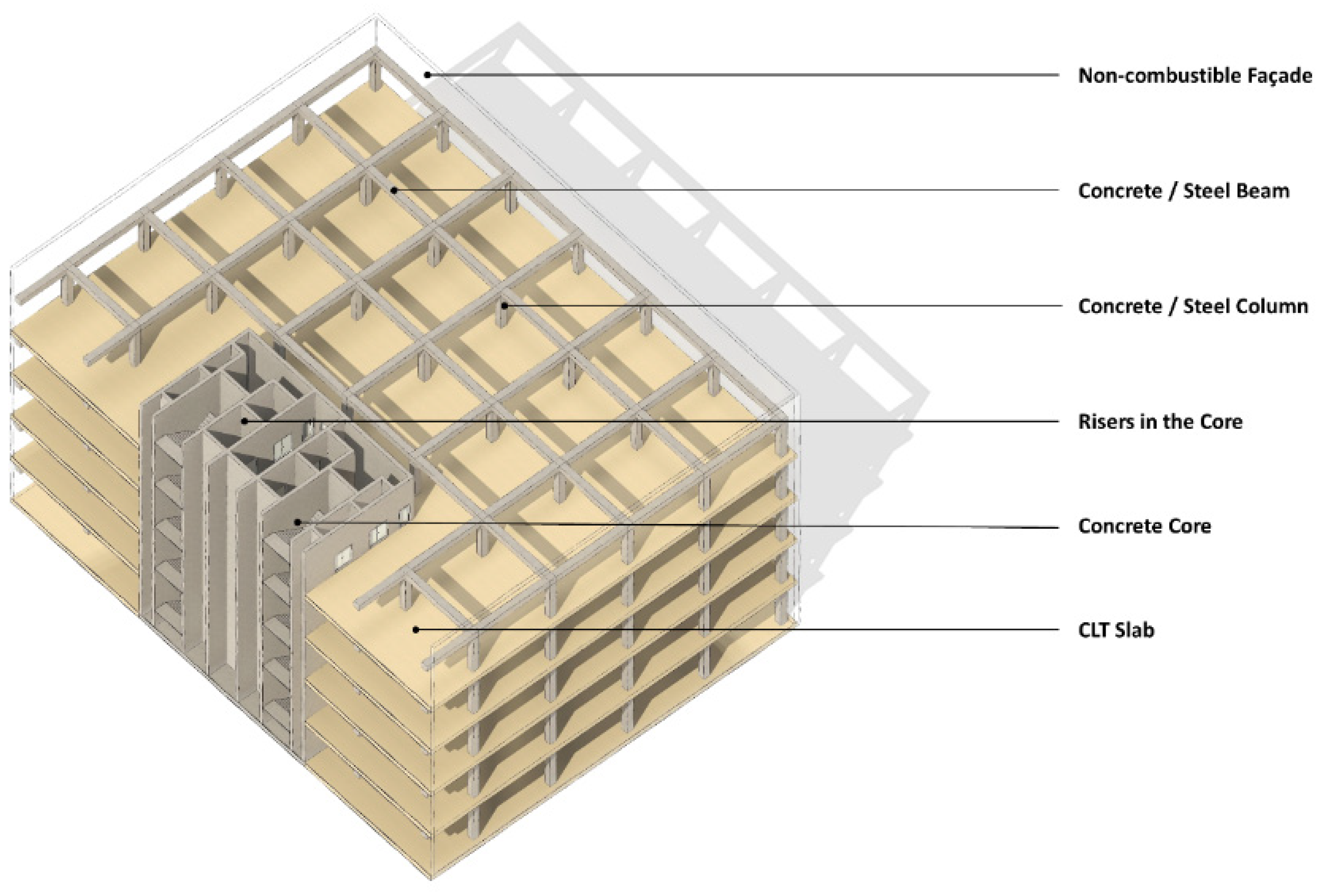
3. Experimental Configuration

3.1. Enclosure Geometry

The geometry of the fire enclosure was chosen to: (a) ensure CLT spans were broadly aligned to that commonly adopted in hybrid commercial (office) construction, with the CLT spanning 3.75 m from front to back, and (b) to be as large as feasible within the constraints of the laboratory, considering both footprint and anticipated peak heat release rate (HRR). This led to an enclosure of internal dimensions of 3.75 m (depth) by 7.6 m (width) by 2.4 m (height). Given commercial construction is typically characterised by a large amount of perimeter glazing, one elevation of the rig featured a large permanent opening, measuring 7.6 m wide and 2.0 m high. To allow for the characterisation of potential external flames from the opening, a mock-up façade extension was included. This extended the full width of the enclosure, measuring 2.6 m in height, with a down-stand that was located 0.4 m below the CLT soffit. The enclosure of the rig was constructed from exposed lightweight concrete blockwork that was 240 mm thick.
The rig was constructed as a free-standing steel frame, with the CLT hung on tension rods from above, allowing load cells to be incorporated within the supporting structure that was outside of the fire enclosure. The CLT was divided into two equal portions, supported on edge-beams that were suspended from their corners off the freestanding steel frame. This created a smooth ceiling with no down-stands/projections.
Further discussion is provided in Section 4 on the support mechanisms and the incorporation of load cells. An image of the rig prior to the first experiment is shown in Figure 2.

3.2. Protection Lining and CLT Specification

The enclosure was utilised to investigate three different CLT specifications:
  • Experiment 1: CLT using a standard polyurethane (PUR) adhesive (Henkel Loctite HB S) lined with 2 × 15 mm thick layers of Type F (fire-rated) plasterboard.
  • Experiment 2: Exposed CLT using a standard polyurethane (PUR) adhesive (Henkel Loctite HB S), with non-edge-bonded facing lamella.
  • Experiment 3: Exposed CLT using a modified PUR adhesive (Henkel Loctite HB X), with edge-bonded facing lamella.
In all cases, the CLT was 160 mm thick, with lay-up 40-20-40-20-40 mm. At the time of the experiments, the estimated moisture content of the CLT slabs was in the range of 12–14% by mass. Non-edge-bonded CLT was chosen in Experiment 2 with the intent of realising a lower bound of fire performance, i.e., the lack of edge-bonding can permit the rapid development of gaps between CLT facing lamella upon heating and subsequent dehydration, followed by pyrolysis. Edge-bonded CLT was chosen to represent an upper bound of fire performance, when combined with the modified PUR adhesive. Edge-bonding is typically considered non-loadbearing and is utilised by selected suppliers of CLT to optimise their manufacturing process.
To form the ceiling of the enclosures, four CLT panels were adopted in each experiment. Each pair of slabs was supported on beams at each end and was designed to permit independent vertical movement for the purposes of measuring mass loss (discussed in Section 4.2). This was achieved by forming simple butt joints without mechanical fixings between each pair of slabs at the half length of the enclosure. The two slabs forming each pair were connected using a simple half-lap joint.

3.3. Fire Source

The ceiling was heated using propane gas burners, elevated to sit 1 m below the soffit. The burner array comprised of 6 burners, each measuring 150 × 300 mm on plan, configured to achieve a rectangle measuring 300 × 900 mm. The burners were located off-centre (at the quarter point), with the aim of inducing flame extension to 50% of the ceiling length in Experiment 1 and a heat flux exceeding 120 kW/m2 at the plume centreline. The HRR of the fire was controlled via mass flow switches, leading to a HRR that ramped to a maximum of 1250 kW (achieved over an 8 min period in 250 kW steps). The intended HRR from the burner array was achieved by adopting a pre-determined mass flow rate of the fuel, which was 95% propane and 5% butane of bulk density 1.85 kg/m3 and with a heat of combustion of 92 kJ/L.
The duration of steady heating (at 1250 kW) for the exposed CLT experiments was chosen to induce significant char fall-off in Experiment 2 (above the burner), resulting in a steady phase duration of 80 min. After this phase, the burners ramped down in 250 kW increments every 5 min, before being switched off. An image during the growth phase of Experiment 3 is shown in Figure 3. Section 5.2 provides further discussion on the enclosure HRR.
In Experiment 1, the steady phase was reduced in duration to 25 min, before following the same ramp down in HRR for Experiments 2 and 3. The corresponding burner time vs. HRR plots are given in Figure 4. The intention of this truncated steady phase HRR for Experiment 1 was to avoid the falling-off of the plasterboard layers upon which ceiling plate thermometers were fixed (see instrumentation discussion in Section 4). This ensured ceiling heat flux estimates could be made without damage to the plate thermometers or uncertainty as to their final positions. When comparing Experiment 1 to Experiments 2 and 3 in later sections, a time-shift is implemented to align the growth and decay phases of all experiments.
In combination with the large ventilation opening, the intent was to generate a localised fire that would induce severe flaming to one slab (i.e., the near field in proximity to the burner array) and reduced heat flux exposure to the second slab (i.e., the far field, away from the burner array). This is comparable to the thermal exposure that might be induced in a large enclosure, should a travelling fire [12,13,14,15] develop in lieu of transitioning to flashover, or in the growth period ahead of transition to flashover.

3.4. Mechanical Loading

Given a stated objective of investigating the impact of char fall-off on the ceiling flaming and auto-extinction characteristics of the CLT slabs, a typical bending stress situation was created through the application of an imposed load. This load was through distributed concrete blocks and steel plates, achieving a nominally uniformly distributed load of 153 kg/m2, or ca. 4300 kg in total.
This configuration was intended to broadly align with the imposed load (quasi-permanent load) expected in an office and equates to 1.5 kN/m2. Based upon the manufacturer’s data, the CLT slabs had a density of 470 kg/m3 at 12–14% moisture content, realising a self-weight of 75 kg/m2 or ca. 0.74 kN/m2.

4. Instrumentation

4.1. Temperature Sensing Devices

An instrumentation plan for temperature sensing devices is shown in Figure 5. This indicates locations of gas-phase (i.e., below the ceiling), in-depth (i.e., within the CLT for Experiments 2 and 3) thermocouples (TCs) and surface mounted plate thermometers (PTs). PT and TC specifications are given below:
  • Surface mounted PTs were equipped with Type K thermocouples, each validated to have precision of ±15 K and comply with Clause 4.5.1.1 of EN 1363-1;
  • Gas-phase and in-depth TCs were all Type K Ni-Cr, 1 mm in diameter, located 30 mm below the ceiling in all cases.
CLT surface (via plate thermometer) and in-depth (via Type K thermocouple) temperatures were measured at locations identified in Figure 5 (for Experiments 2 and 3 only). In the near field, i.e., in proximity to the burner array, in-depth thermocouples were placed at 20, 40, 60, 80 and 100 mm depths. This reduced to 20, 40 and 60 mm depths in the far field, see Figure 6.

4.2. Load Cells and Displacement Transducers

The CLT support structure was an innovative form, comprising a perimeter steel frame, from which each pair of CLT slabs were suspended via tension rods. In line with these tension rods were a load cell to each corner, i.e., 8 in total, recording the tensile load acting on the supports. The arrangement is as shown indicatively in Figure 7. The slabs sat within the perimeter of blockwork wall enclosure, ensuring the CLT and supporting structure were not propped by the perimeter wall. Minor gaps at the ceiling edges were fire stopped with mineral wool.
The mid-span deflection of each pair of slabs was measured via a Linear Variable Differential Transformer (LVDT). The mass of each pair of slabs was measured throughout each experiment, using four load cells per pair of slabs. The load cells were S-beam FN9620 force sensors, each with a capacity of 10 kN.

5. Results

5.1. CLT Mass Loss and Mass Loss Rate

Using the forces output from the eight load cells discussed in Section 4.2, the cumulative CLT mass loss for Experiments 2 and 3 are shown to the left of Figure 8. The right-hand side of Figure 8 is the corresponding mass loss rate, determined through differentiation of the slab mass loss with respect to time. This represents a mean mass loss rate, which has been normalised relative to the slab exposed area in the enclosure (i.e., 3.75 × 7.6 m).

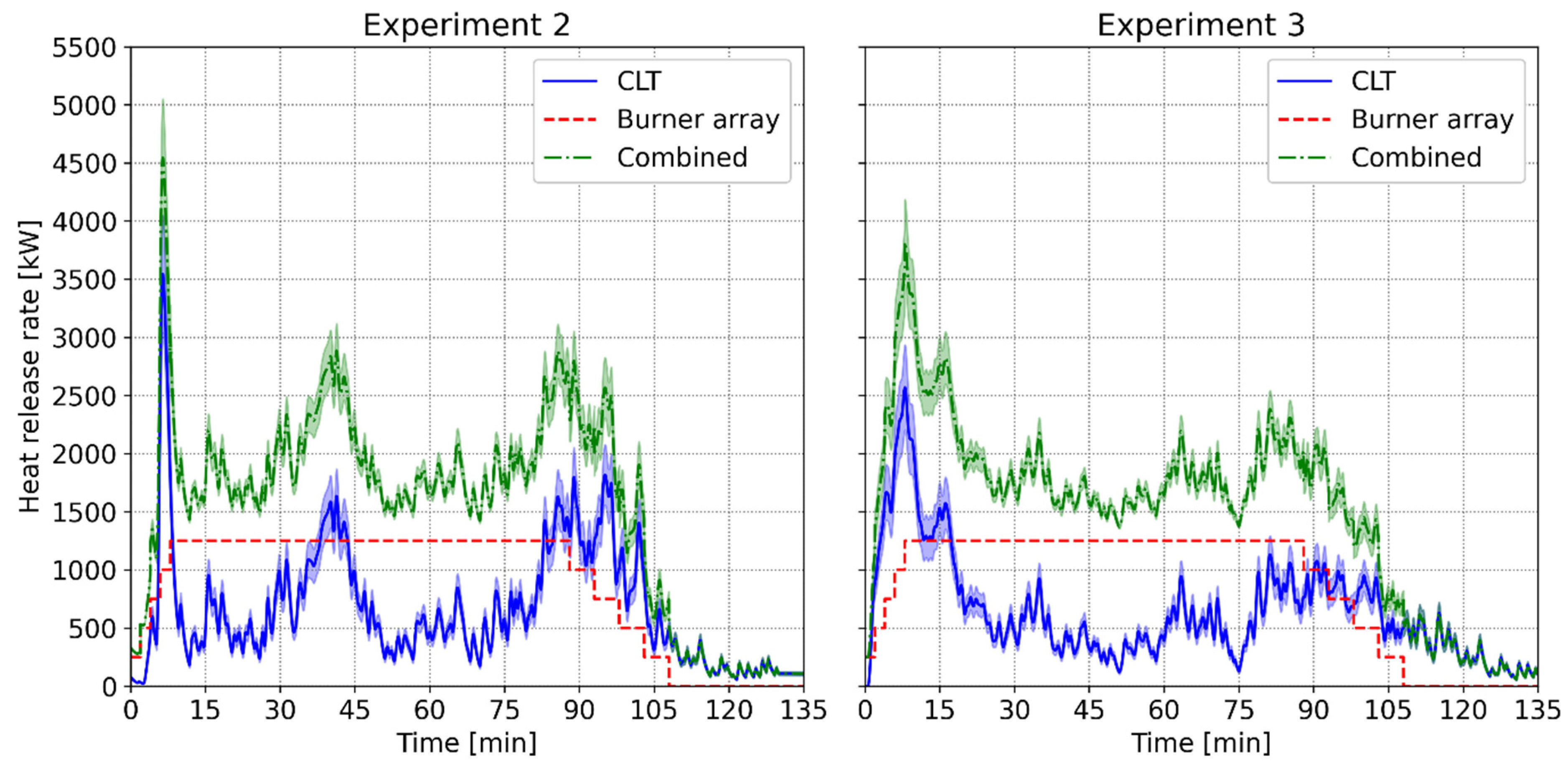
5.2. Heat Release Rate

The estimated HRR is shown in Figure 9 for Experiments 2 and 3. For Experiment 1, the HRR is simply that of the propane burners (see Figure 4). The CLT contribution to the HRR is estimated from the load cells, with the shaded envelope corresponding to a heat of combustion of wood of 17,500 ± 2,500 kJ/kg, as reported in Bartlett et al. [10].
The enclosure HRR is characterised by a transient phase, corresponding to ignition and the development of a char layer, followed by a steadier phase where the mass loss rate (and correspondingly HRR) does not vary much with time (i.e., once the char layer is established). In Experiment 2, two char fall-off events are apparent at ca. 40 and 80 min (albeit observed to be detachment of the first lamella in two separate locations due to the non-uniform heating regime), leading to increases in the HRR. Such events are less apparent in Experiment 3 where the HB X adhesive was adopted, albeit increases in HRR do manifest at ca. 60 and 80 min, which corresponded to some observations of char fall-off.

5.3. CLT Surface and In-Depth Temperatures

Temperature plots over the duration of each experiment are provided in Figure 10 (Experiment 1), Figure 11 (Experiment 2) and Figure 12 (Experiment 3). In the case of Experiments 2 and 3, data logging continued beyond the burners being switched off.

5.4. Ceiling Gas-Phase Temperatures

Figure 13 presents ceiling gas temperatures for locations indicated in Figure 5. Thermocouple data are smoothed using a 5 s exponentially weighted average. To align the decay phase of the shorter duration Experiment 1 with that of Experiments 2 and 3, a time-shift has been implemented, as annotated in Figure 13 and previously discussed in Section 3.3.

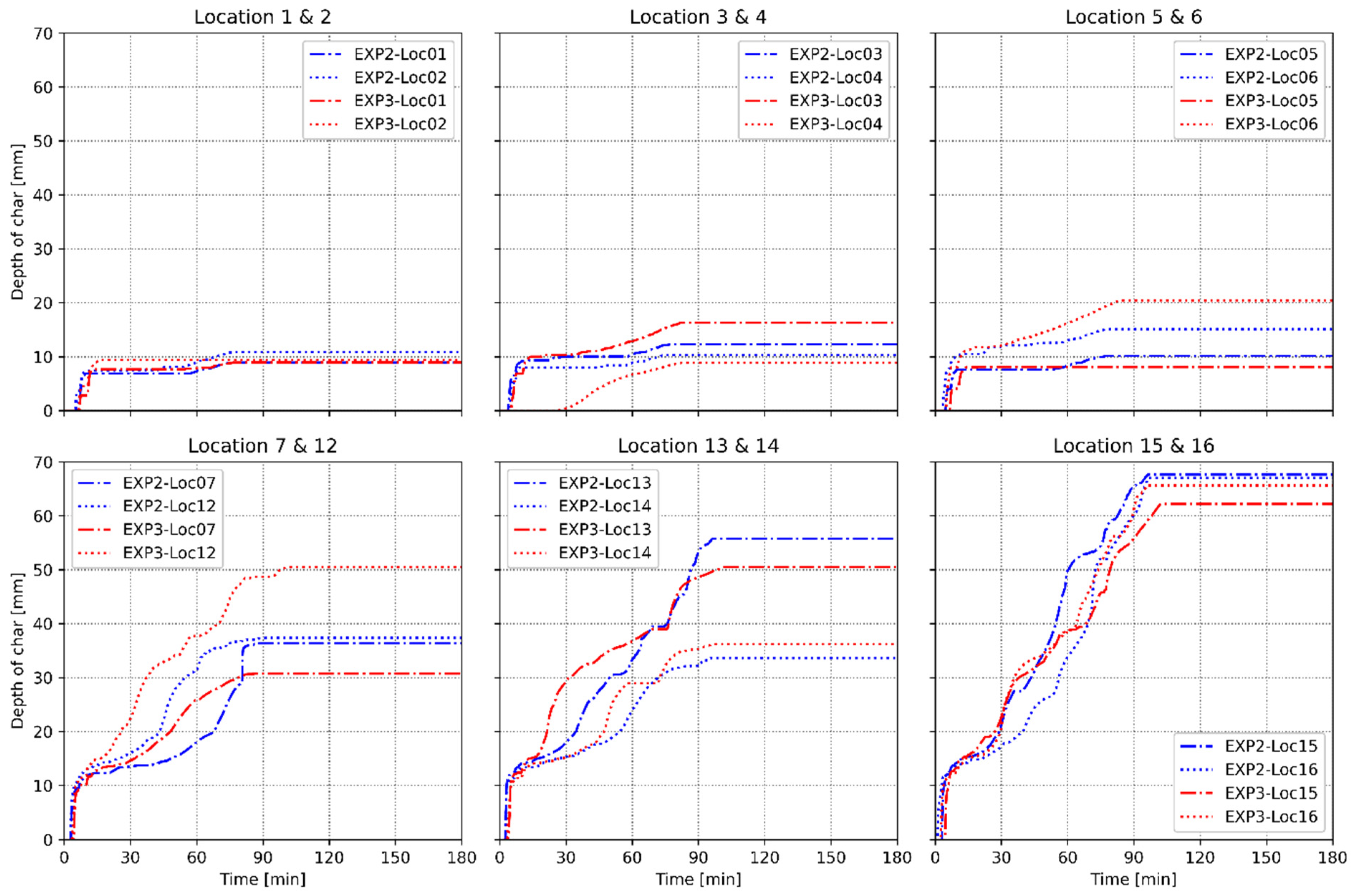
5.5. Charring Depths

The depth of char in function of time at different ceiling locations for Experiments 2 and 3 is shown in Figure 14. Given the express intent of averting the involvement of the CLT substrate in Experiment 1, no charring was observed.
The depth of char was estimated based on the 300 °C isotherm position, linearly interpolating from the temperature data shown in Section 5.3 and determined from in-depth thermocouples. Locations move progressively from the far field (away from the burner array) towards the near field (in proximity to the burner array).
As thermocouples were installed from the top of the CLT elements and, hence, were located perpendicular to the anticipated isotherms, there is the potential for char depths to be underestimated. This is due to conduction losses from the thermocouple tip, along the sheathing, with further discussion provided in Pope et al. [16]. No corrections were applied to address this potential source of error.

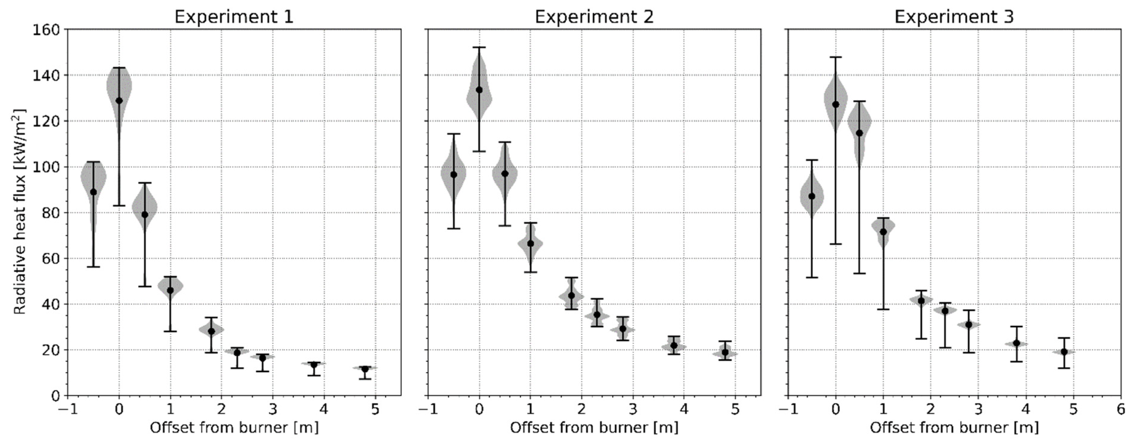
5.6. Ceiling Radiative Heat Flux Measurements

Ceiling mounted plate thermometers (PT) were utilised to estimate the radiative heat flux to the ceiling, adopting the correlations presented in Wickstrom et al. [17], as adopted by other researchers for similar applications, e.g., Su et al. [18].
Neglecting the heat storage term of the energy balance of the PT, as per Ingason and Wickstrom [19], the radiative heat flux was derived according to Equation (1):
q ˙ inc = ε pt σ T pt 4 + ( h + K cond ) ( T pt T ) ε pt
Relevant terms for the purpose of estimating q ˙ i n c are given in Table 1. Heat transfer constants and correction factors for the PT are taken from Häggkvist et al. [20], as adopted by Su et al.
Figure 15 shows the radiative heat flux to the ceiling in function of time for the three experiments. Figures for the near field are shown first, before progressively moving further away from the burner. As previously, to align the decay phase of Experiment 1 with that of Experiments 2 and 3, a time-shift has been implemented, as annotated in Figure 15.

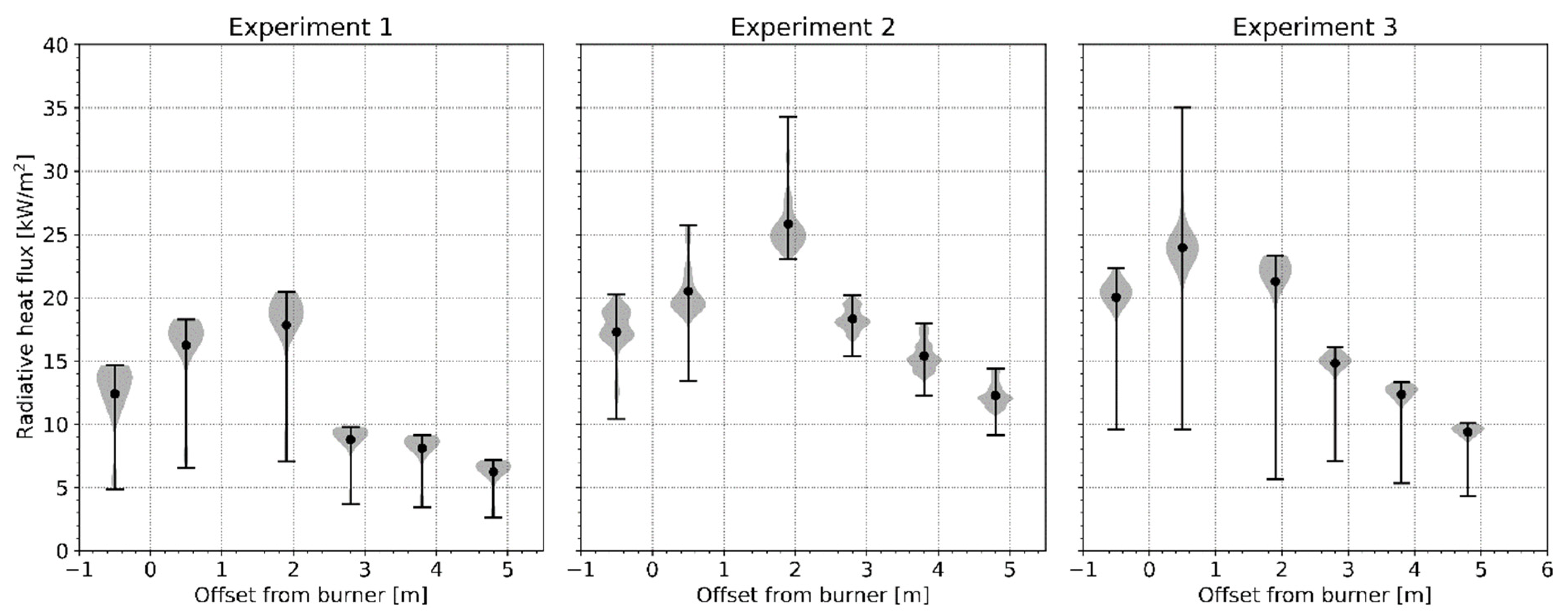
5.7. Floor Radiative Heat Flux Measurements

Floor mounted PTs were adopted to estimate the radiative heat flux to the floor, with the correlations and constants as previously defined in Section 5.6. Figure 16 plots radiative heat flux to the floor in function of time for the three experiments. As per Section 5.6, figures are presented so as to progress from the far field towards the burner array. Floor locations correspond with the positions given in the instrumentation ceiling plan shown in Figure 5, with all PTs located on the floor of the lab, facing upwards.
During Experiment 2, a small area of burning (ca. 200 × 200 mm) was observed on the floor of the enclosure after ca. 35 min, but this was not attributed to char fall-off. It is provisionally speculated that a pocket of adhesive or resin may have been present, which upon heating seeped through the first lamella of the CLT before burning as a small pool fire in proximity to the PT located at position 12.

5.8. CLT Slab Deflection

CLT mid-span downward deflections were monitored via LVDT, as illustrated in Figure 17. The pair of slabs above the burner array (denoted “Near-field pair”), peak deflections reached ca. 14 vs. 16 mm, for Experiments 2 and 3, respectively. In the far field, i.e., the pair of slabs away from the burner array (denoted “Far-field pair”), the corresponding peaks reduce to ca. 7 mm in both cases.

6. Analysis and Observations

6.1. Char Fall-Off and Bond-Line Failure Terminology

For the purposes of discussing the observations from the experiments reported herein, the following terms are defined based upon the phenomena and underlying mechanisms witnessed:
  • Bond-line failure (BLF) is defined herein as the failure, in this case due to heating, of the adhesion between lamella, leading to its detachment;
  • Char fall-off is the detachment of charred pieces of lamella. BLF may be an underlying mechanism that leads to premature char fall-off (as commonly observed with standard PUR adhesives) or char fall-off may occur without BLF, i.e., there is a loss of connectivity between the char and its substrate that may occur away from bond-lines.
Henceforth, the term BLF can be considered to be associated with premature char fall-off, leading to larger pieces of lamella detaching and falling, and is only used in this context.

6.2. CLT Implications for Heat Release Rate

Figure 9 shows the relative contributions of the enclosure heat release rate attributable to the propane burners and combustion of the CLT. Ignition of the majority of the CLT soffit was observed to occur in both Experiments 2 and 3 as the propane burner array approached a peak heat release rate of 1250 kW. Upon ignition, the CLT contribution to the HRR peaked at ca. 3500 kW in Experiment 2 vs. 2500 kW in Experiment 3. This equated to a total HRR, i.e., inclusive of the burner array, of ca. 4750 kW in Experiment 2 vs. 3750 kW in Experiment 3. That is, upon involvement of the CLT, the peak enclosure HRR was at least three times greater than the plasterboard-lined reference enclosure. However, this peak only lasted ca. 30 s.
As a char layer progressively formed, the mass loss rate of the CLT reduced in both Experiments 2 and 3. A pseudo-steady-state HRR from the CLT followed until char fall-off was observed, leading to increases in the CLT HRR. This is most evident in Experiment 2, where BLF was noted, with spikes in CLT HRR observed at ca. 40 min from ignition and ca. 80 min from ignition. At the end of the experiment, it was evident that the first two lamella of the CLT in Experiment 2 had detached in the vicinity of the burner array. Char fall-off was observed towards the end of the 1250-kW steady phase in Experiment 3. However, this typically involved small areas of char, differing from the detachment of large pieces of lamella witnessed in Experiment 2. The largest pieces of detached lamella were observed as being up to 400 mm long and a full plank width (ca. 100 mm) in Experiment 2 and were generally located in proximity to the burner array where charring depths were greatest. No char fall-off was observed away from the areas where the burners impinged upon the ceiling in either experiment.
Over the period where the burner array HRR was capped at 1250 kW, the CLT contribution to the HRR averaged 586 and 538 kW for Experiments 2 and 3, respectively. This equated to a 47 and 43% increase in HRR during this steady phase when benchmarked relative to the plasterboard-lined reference experiment.

6.3. Adhesive Choice and Auto-Extinction of CLT Ceilings

It has been noted that the CLT soffits in both Experiments 2 and 3 ignited, with most of the surface observed as flaming as the burner transitioned to 1250 kW. Figure 18 shows this flaming in Experiment 3.
As discussed in Section 6.2, char fall-off was observed in both Experiment 2 and Experiment 3. However, the more severe events leading to the detachment of large pieces of lamella were only witnessed in Experiment 2. This was as anticipated, with Experiment 2 adopting a standard PUR adhesive (HB S) and Experiment 3 adopting a modified PUR adhesive (HB X). Despite char fall-off in both exposed CLT experiments, auto-extinction was progressively observed to occur, starting at the wall most remote from the burner array and gradually moving inwards as the burners HRR ramped down. Auto-extinction above the burner array was only observed once the burners were switched-off, with radiative heat fluxes then dropping below ca. 40 kW/m2. Photographs of the ceilings in proximity to the burner array for Experiments 2 and 3 are shown in Figure 19 and Figure 20, respectively.
It is a longstanding principle in the fire science literature that timber cannot sustain combustion without the presence of an external heat flux, i.e., see the discussion on auto-extinction in Drysdale [21], Bartlett et al. [10] and Brandon et al. [22]. However, despite this, averting BLF and subsequent extensive/premature char fall-off is often seen as a condition imposed on designs as such events have the potential to cause “an undesirable feedback loop such as fire re-growth” [23]. As is noted in Ronquillo et al. [11], such observations emanate from enclosures where either multiple CLT surfaces were exposed or they had the potential to become exposed through encapsulation failures. In such situations, particularly where walls are exposed and able to suffer extensive char fall-off, it was often observed that collections of smouldering char at the base of the wall were sufficient to allow the walls to continue to undergo flaming combustion, subsequently impacting their ability to auto-extinguish. What is evident from this study is that BLF (leading to more significant/premature char fall-off) is of secondary importance to the incident heat flux received by the combustible surfaces. Whilst significant char fall-off was witnessed above the burner array, the detached lamella fell sufficiently far away from the combustible soffit so as to ensure the subsequent heat flux arising from the lamella’s combustion on the floor was negligible. As a result, once the heat flux from the burners reduced to a sufficiently low level (ca. 40 kW/m2 in both experiments), auto-extinction occurred regardless. It follows that it is the configuration of the enclosure and its exposed surfaces that most heavily impacts the ability of the structure to undergo auto-extinction, not whether significant char fall-off occurs. However, as highlighted in the literature review by Ronquillo et al., where this detached char lands, e.g., forming a pile at the base of a wall, may be a contributing factor as to whether auto-extinction can ultimately occur. Such a factor has limited relevance where only an exposed CLT ceiling is present.
The potential for BLF, leading to significant/premature char fall-off, must be balanced against the structural demands on the section. Such events have the potential to increase charring depths and heat affected zones, thus reducing the load-bearing capacity of the section. That is, whilst averting BLF and subsequent premature char fall-off for configurations of the like presented herein is not a prerequisite for auto-extinction, the compromise will often be larger cross-sections to accommodate the corresponding loss of material.

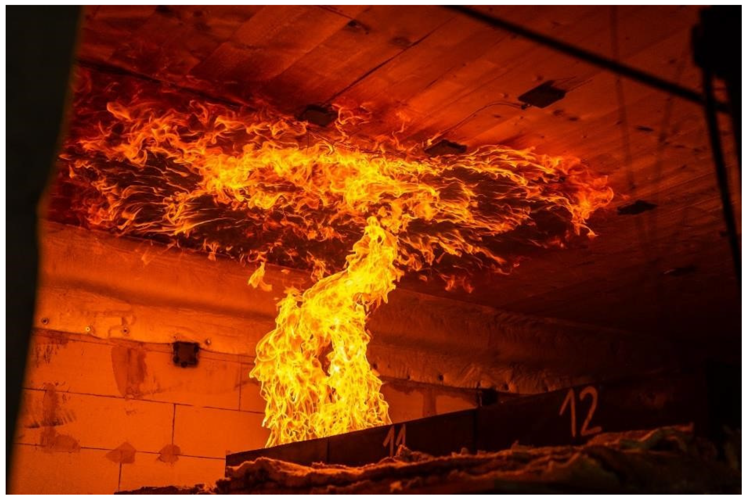
6.4. Flame Extension and Implications for Ceiling Thermal Exposure

Section 5.6 has presented the transient evolution of radiative heat flux to the ceiling for the three experiments conducted. Adopting a flame tip incident heat flux in line with that reported by Lattimer [24] of ca. 20 kW/m2, Experiment 1 was successful in achieving flame extension below the plasterboard ceiling to approximately half of the enclosure length, i.e., location 22 in Figure 5. For Experiments 2 and 3, a radiative heat flux of more than 20 kW/m2 was observed over most of the full length of the enclosure until the burner array HRR entered the decay phase, i.e., extending as far as location 1.
In the immediate vicinity of the burner array, i.e., locations 13 and 14, nominal differences in radiative heat flux to the ceilings were observed across the experiments, suggesting the heat flux from the burner array dominates in the near field.
Figure 21 presents the flame extension profile in the form of a violin plot whilst the burner array heat release rate is 1250 kW. At each offset from the burner array centre, the plot indicates the range of values adopted (the bar) and their probability distribution (the shaded region). The mean value is shown as a dot. Where the probability density is greatest, the shaded region is widest. A high probability density close to the end of a range bar would imply outcomes tending towards an extreme-type distribution [25].
Outside of the ceiling distance where the propane burner array impinges, i.e., beyond a ca. 2.3 m offset from the burners, Experiments 2 and 3 indicate a consistent increase in radiative heat flux, relative to Experiment 1, of between 15 and 20 kW/m2. In small-scale experimental studies by both Spearpoint and Quintiere [26] and Morrisset et al. [27], this increase broadly equates to the heat flux to the surface of wood from its own flame.

6.5. Implications of Ceiling Flame Extension for Internal Fire Spread

Section 5.7 has presented the evolution of radiative heat flux to the floor with time for the three experiments. Figure 22 represents this data in the form of a violin plot whilst the burner array heat release rate was 1250 kW.
Table 2 compares the mean and changes in mean radiative heat flux to the floor, relative to the plasterboard-lined reference enclosure (Experiment 1). Over the steady phase where the burner array was capped at 1250 kW/m2, the estimated radiative heat flux to the floor is increased in all locations for the exposed CLT soffit experiments (Experiments 2 and 3) relative to the plasterboard-lined reference experiment.
Near the burner array, Experiment 3 (which adopted a modified PUR adhesive) results in higher estimated radiative heat flux to the floor. This may be due to the ability of the char to remain attached for longer, reducing the heat losses to the CLT. Small-scale experiments reported in Hopkin et al. [28] note the chosen modified adhesive (HB X) to have performance characteristics that generally reduce charring rates through the course of heating and not just improve the ability of the char to remain attached.
Away from the burner array, i.e., at +1900 mm and beyond, Experiment 2 consistently shows an increase in estimated radiative heat flux to the floor relative to Experiment 3. Through the course of Experiment 2, as discussed in Section 6.2, char fall-off was seen to occur on multiple occasions to the CLT slab above the burner array, leading to the detachment of larger pieces of lamella. Further flaming followed until a char layer re-formed. This led to observations of flaming over a greater proportion of the ceiling to the enclosure in Experiment 2 vs. Experiment 3, as evident in discussions in Section 6.4. It is anticipated that this prolonged and more extensive ceiling flaming is attributable to the increased estimated radiative heat fluxes to the floor away from the burner array.
The format of the experiments undertaken, i.e., with a discrete heat source and otherwise fuel load free enclosure, did not permit any direct evaluation of what the combustible ceiling might mean for flame spread rates within a large enclosure. However, the radiative heat flux to the floor provides insight as to what might be expected through benchmarking against complementary studies, such as that by Gupta et al. [29]. In their studies on mechanisms of flame spread in large enclosures, Gupta et al. observe correlation between the external heat flux to the fuel in advance of the flame front and the flame front velocity. In a proposed phenomenological model, Gupta et al. postulated that as the external heat flux to the fuel in advance of the flame front converges on a critical ignition criterion (taken as 10.5 kW/m2 therein), the ratio of flame front to burn-out front velocity tends towards infinity, i.e., the flame spread rate is so fast so as to induce a “Mode 1” fire, which implies a fully developed post-flashover fire.
With reference to Figure 22, much of the floor in the far field of Experiment 1 receives a radiant heat flux of less than 10.5 kW/m2, meaning if the facility existed to spread, it would likely result in either a growing fire (Mode 2) or a steady-moving/travelling fire (Mode 3). In Experiments 2 and 3, much of the floor in the far field receives a radiant heat flux significantly above 10.5 kW/m2, implying that the combustion of the ceiling would induce a change from a Mode 2 or 3 fire to Mode 1 (i.e., extremely rapid flame spread and transition to flashover). Such a rate of flame spread is supported by recent observations by Kotsovinos et al. [23] in their fire experiment in a 352 m2 enclosure with exposed CLT ceiling. In Kotsovinos et al.’s “CodeRed #01” experiment, once ignition of the ceiling occurred, flame spread over the cribs covering the full length of the enclosure was observed in under 3 min.

6.6. Charring Depths and Estimate of Equivalent Duration of Furnace Exposure

The transient evolution of the char depth at different locations across the exposed slabs in Experiments 2 and 3 has been presented in Section 5.5. For each of the locations where in-depth CLT temperatures were measured, as identified in Figure 5, a boxplot of final charring depth is shown in Figure 23. Separate plots are shown for each exposed CLT experiment and each pair of CLT slabs, i.e., the pair of slabs above the burner array (near) and the pair of slabs away from the burner array (far).
For the far field slabs, regardless of the adhesive type, the charring depth is low with a mean value of 10.5 mm for Experiment 2 vs. 10.3 mm for Experiment 3. For the near slabs, the charring depth varies substantially as the distance from the burner array increases. The mean values of the near field slabs charring depth are, however, consistent between adhesive types, yielding 44.7 vs. 45.2 mm for Experiment 2 and 3, respectively.
To benchmark the severity of the thermal exposure to the slabs at various locations, the charring depths are divided by charring rates commonly observed in standard fire resistance testing furnace conditions, with results shown in Table 3. For this purpose, a charring rate of 0.65 mm/min is adopted from EN 1995-1-2 [30] for all slabs. This is likely to overestimate the equivalent duration of furnace heating for locations where BLF and subsequent premature char fall-off was observed, with it commonly noted that the charring rate in furnace conditions subsequently increases until such time that a char layer has redeveloped. Near the burner array, the corresponding equivalent duration of furnace heating broadly aligns with fire resistance ratings advocated for medium- to high-rise commercial premises in guidance documents such as Approved Document B [31] and BS 9999 [32].

6.7. Structural Stability

The CLT slabs were loaded to mimic an imposed load compatible with that of an office. Loading was primarily applied to ensure that stresses in the CLT elements were broadly consistent with that which might be expected to occur in practice, thus ensuring any BLF and subsequent premature char fall-off behaviours arising from load induced actions were captured.
For both exposed CLT slab experiments (Experiments 2 and 3), the structure supported the applied loads during and beyond the switching off of the propane burners. At no point did CLT slab mid-span downward deflections highlight any “run-away” behaviour, with deflections gradually increasing with time before stabilising once the burners were switched off.
Peak deflections of 14 and 16 mm were observed for Experiments 2 and 3. These occurred directly above the burner array, where the heating was most severe and the charring depths greatest. The deflections equate to ca. span/270 and span/235 for Experiments 2 and 3, respectively. This is well within the deflection limits typically adopted in fire resistance testing standards, which can be as high as span/20 [33].

7. Conclusions

This paper has reported on three large-scale fire experiments conducted on plasterboard-lined and exposed CLT ceilings. The CLT adopted different edge-bonding procedures and inter-lamella PUR adhesives, with Experiment 2 using non-edge-bonded CLT with standard PUR (HB S) adhesive and Experiment 3 using edge-bonded CLT with modified PUR (HB X) adhesive.
The experiments were extensively instrumented with the aims of determining the CLT contribution to the HRR, the heat fluxes to various surfaces forming the enclosure, temperature profiles and charring depths within the CLT and CLT deflection.
The slabs were exposed from below via an array of propane burners which achieved a peak HRR of 1250 kW. The combination of burner array position and heat output was chosen to induce flame extension to ca. 50% of the ceiling in Experiment 1, allowing further flame extension to be observed, should it occur, in Experiments 2 and 3.
Based upon the analysis of results presented herein, the following conclusions are made:
  • Upon initial ignition/involvement of the CLT, the experiments featuring exposed CLT (Experiments 2 and 3) delivered a peak HRR that was up to three times larger than that of the plasterboard lined reference (Experiment 1).
  • During the steady phase of fire development, where the propane burners remained at 1250 kW, the contribution of the CLT stabilised at ca. 500 kW, with nominal difference between the two CLT specifications adopted.
  • Premature char fall-off was observed in Experiment 2 and typically coincided with BLF, leading to detachment of larger pieces of lamella in proximity to the burner array. These events were observed to occur several times (estimated as ca. 5 in total), with the detached lamella measuring up to ca. 400 mm long and 100 mm in width. This led to spikes in the CLT slab mass loss rate and, correspondingly, HRR. Char fall-off was witnessed in Experiment 3, although this did not appear to be whole parts of lamella and were instead smaller pieces of char of the scale of ca. 50 mm square. Consequently, this had a less pronounced influence on the measured CLT mass loss rate and HRR.
  • Despite quite significant premature char fall-off in Experiment 2, auto-extinction of the slabs was observed once the burner array was switched off. This aligned with observations for Experiment 3, where char fall-off was limited. It can, therefore, be concluded that for the configuration studied, i.e., an exposed ceiling with otherwise inert boundaries, averting significant char fall-off was not a prerequisite for the cessation of flaming combustion. Whilst fresh timber was increasingly exposed in Experiment 2, the incident heat flux to the CLT ultimately reached a level where flaming combustion could not continue (in this case, below ca. 40 kW/m2). The detached lamella was seen to fall to the floor and flame for a period, before transitioning to smouldering. The heat flux from the fallen flaming or smouldering lamella made no material impact to that received at ceiling level.
  • Premature char fall-off resulted in local significantly reduced residual CLT sections in Experiment 2 that were not apparent in Experiment 3, with the third lamella from the exposed side visible for the CLT adopting standard PUR adhesive. Therefore, whilst averting significant char fall-off was not a prerequisite for auto-extinction, it would be expected to come with the compromise of increased section depth to ensure adequate mechanical performance in the event of fire.
  • Despite pronounced char fall-off events in Experiment 2, mean charring depths to the slabs above the burner array were comparable for both adhesive types studied, reaching ca. 45 mm in both cases based upon estimates of the 300 °C isotherm positions measured via in-depth thermocouples. This could be due to the mechanical fixing of PTs to the ceiling nearby, which locally prevented the detachment of the lamella which was observed elsewhere in Experiment 2.
  • In Experiment 1, flame extension was observed over ca. 50% of the plasterboard-lined ceiling, with a radiative heat flux of 20 kW/m2 noted at PTs located halfway along the rig. Upon involvement of the CLT in Experiments 2 and 3, this flaming was observed to extend over the entire enclosure ceiling area, with heat fluxes in the far field consistently ca. 20 kW/m2 higher than that observed in Experiment 1.
  • The increased flame extension at the ceiling level translated to increased radiative heat flux to the floor in both Experiments 2 and 3, when measured relative to Experiment 1. Based upon the magnitude of these radiative heat flux measures (>10 kW/m2), it is postulated that if the experiment had the facility to accommodate flame spread over fuel load on the floor, it would have been rapid. Through benchmarking against the studies of Gupta et al., it is foreseen that in many large enclosures with exposed CLT ceilings, a “Mode 1” (post-flashover) fire would ensue owing to the large heat fluxes observed to the floor in advance of the fire front. This is consistent with observations from recent large enclosure fire experiments with exposed CLT ceilings [23].
  • Despite significant section loss in the vicinity of the burner, with char depths estimated to be ca. 70 mm in locations, the CLT ceiling remained structurally stable under load, both during and beyond the thermal exposure from the propane burner array. Little deflection was observed, reaching a maximum of 14 mm in Experiment 2 and 16 mm in Experiment 3.
Based upon the findings of other studies conducted as part of the larger STA project, it is expected that the results of these experiments would be applicable to CLT manufactured by different suppliers, subject to consistency in moisture content, adhesive type, edge-bonding condition, CLT thickness and CLT lay-up. Studies reported in Hopkin et al. [28] noted there to be nominal differences in the fire behaviour characteristics of CLT from three different leading suppliers, subject to the same specification parameters. It is expected that such a small-scale testing format/regime could be utilised to inform whether the data developed from the large-scale experiments reported herein could be applicable to a given product/supplier.
The data gathered and presented herein will be the focus of ongoing analyses to better understand various aspects, most notably:
  • The enclosure energy balance, with emphasis on large enclosures and auto-extinction. In particular, the fidelity of data collected herein provides a means for the development and validation of computational models that could be used to estimate fire development behaviours in large enclosures.
  • The study has highlighted that modified PUR offers benefits over standard PUR in terms of mitigating premature char fall-off due to bond-line failure, although the mean charring depths across locations were not significantly different across adhesive types. Given this, there is merit in further understanding the mechanisms through which modified PUR offers enhanced performance over standard PUR. Further study is proposed to better understand mechanical performance using Dynamic Mechanical Analysis (DMA) and moisture transport using Nuclear Magnetic Resonance (NMR) methods.
  • How the mechanical resistance of the CLT slabs may have evolved with time, noting limited deflection was observed, and how this might vary between the two adhesive types adopted.
  • What impact ceiling protrusions, such as glulam beams, might have on the conclusions drawn herein, particularly regarding auto-extinction and the relationship with bond-line failure and subsequent premature char fall-off, flame extension across the ceiling and the corresponding impact on heat flux to the floor/flame spread.

Author Contributions

D.H.—conceptualization, methodology, formal analysis, writing—original draft preparation, project administration. W.W.—conceptualization, methodology, investigation, writing—review and editing. M.S.—conceptualization, methodology, writing—review and editing. I.F.—data curation, formal analysis. H.K.—conceptualization, supervision, project administration, funding acquisition, writing—review and editing. T.S.—conceptualization, supervision, project administration, funding acquisition, writing—review and editing. C.G.—conceptualization, supervision, project administration, funding acquisition, writing—review and editing. G.S.—supervision, writing—review and editing. All authors have read and agreed to the published version of the manuscript.

Funding

The funding made available by Stora Enso, KLH and Binderholz to undertake this work is gratefully acknowledged.

Institutional Review Board Statement

Not applicable.

Informed Consent Statement

Not applicable.

Data Availability Statement

Not applicable.

Acknowledgments

The authors wish to acknowledge the contributions of the wider STA project team, including the discussions and technical contributions made by the Structural Timber Association (STA), BK Structures and Eurban.

Conflicts of Interest

Carmen Gorska (Stora Enso), Harald Krenn (KLH) and Tim Sleik (Binderholz) are members of the technical team within their respective organisations, all of which provided funding to undertake the work presented. Gordian Stapf (Henkel) is a member of the technical team within the organisation who develops, manufactures and sells the adhesives used to bond lamella within the CLT studied herein (both standard and modified PUR).

References

  1. Structural Timber Association. Mass timber structures. In Structural Timber Buildings Fire Safety in Use Guidance; Building Regulation Compliance B3(1), V1.1; Structural Timber Association: Alloa, UK, 2020; Volume 6. [Google Scholar]
  2. Hopkin, D.; Spearpoint, M.; Gorksa, C.; Krenn, H.; Sleik, T.; Milner, M. Compliance road-map for the structural fire safety design of mass timber buildings in England. SFPE Eur. Q 2020, 4, 27–34. [Google Scholar]
  3. Structural Timber Association. CLT Special Interest Group. 2021. Available online: http://www.structuraltimber.co.uk/sectors/clt-special-interest-group (accessed on 4 May 2021).
  4. Law, A.; Bisby, L. The rise and rise of fire resistance. Fire Saf. J. 2020, 116, 103188. [Google Scholar] [CrossRef]
  5. Law, A.; Hadden, R.M. Burnout Means Burnout. SFPE Eur. Q 2017, 1. Available online: https://www.sfpe.org/page/Issue5Feature1 (accessed on 2 October 2019).
  6. Law, A.; Hadden, R.M. We need to talk about timber: Fire safety design in tall buildings. Struct. Eng. J. Inst. Struct. Eng. 2020, 98, 10–15. [Google Scholar]
  7. Gorska, C.; Hidalgo, J.P.; Torero, J.L. Fire dynamics in mass timber compartments. Fire Saf. J. 2020, 120, 103098. [Google Scholar] [CrossRef]
  8. Emberley, R.; Putynska, C.G.; Bolanos, A.; Lucherini, A.; Solarte, A.; Soriguer, D.; Gonzalez, G.; Humphreys, K.; Hidalgo, J.P.; Maluk, C.; et al. Description of small and large-scale cross laminated timber fire tests. Fire Saf. J. 2017, 91, 327–335. [Google Scholar] [CrossRef] [Green Version]
  9. Bartlett, A. Auto-Extinction of Engineered Timber. Ph.D. Thesis, University of Edinburgh, Edinburgh, UK, 2018. [Google Scholar]
  10. Bartlett, A.I.; Hadden, R.M.; Bisby, L.A. A review of factors affecting the burning behaviour of wood for application to tall timber construction. Fire Technol. 2019, 55, 1–49. [Google Scholar] [CrossRef] [Green Version]
  11. Ronquillo, G.; Hopkin, D.; Spearpoint, M. Review of large-scale fire tests on cross-laminated timber. J. Fire Sci. 2021, 39, 327–369. [Google Scholar] [CrossRef]
  12. Stern-Gottfried, J.; Rein, G. Travelling fires for structural design—Part I: Literature review. Fire Saf. J. 2012, 54, 74–85. [Google Scholar] [CrossRef] [Green Version]
  13. Stern-Gottfried, J.; Rein, G. Travelling fires for structural design—Part II: Design methodology. Fire Saf. J. 2012, 54, 96–112. [Google Scholar] [CrossRef] [Green Version]
  14. Rackauskaite, E. iTFM: Improved Travelling Fires Methodology for Structural Design and the Effects on Steel Framed Buildings. Doctoral Dissertation, Imperial College London, London, UK, 2017. [Google Scholar] [CrossRef]
  15. Heidari, M.; Kotsovinos, P.; Rein, G. Flame extension and the near field under the ceiling for travelling fires inside large compartments. Fire Mater. 2020, 44, 423–436. [Google Scholar] [CrossRef]
  16. Pope, I.; Hidalgo, J.P.; Hadden, R.M.; Torero, J.L. A simplified correction method for thermocouple disturbance errors in solids. Int. J. Therm. Sci. 2022, 172, 107324. [Google Scholar] [CrossRef]
  17. Wickström, U.; Anderson, J.; Sjöström, J. Measuring incident heat flux and adiabatic surface temperature with plate thermometers in ambient and high temperatures. Fire Mater. 2019, 43, 51–56. [Google Scholar] [CrossRef] [Green Version]
  18. Su, J.; Lafrance, P.-S.; Hoehler, M.; Bundy, M. Fire Safety Challenges of Tall Wood Buildings-Phase 2: Task 2 & 3-Cross Laminated Timber Compartment Fire Tests; FPRF-2018-01; Fire Protection Research Foundation: Quincy, MA, USA, 2018. [Google Scholar]
  19. Ingason, H.; Wickström, U. Measuring incident radiant heat flux using the plate thermometer. Fire Saf. J. 2007, 42, 161–166. [Google Scholar] [CrossRef]
  20. Häggkvist, A.; Sjöström, J.; Wickström, U. Using plate thermometer measurements to calculate incident heat radiation. J. Fire Sci. 2013, 31, 166–177. [Google Scholar] [CrossRef]
  21. Drysdale, D. An Introduction to Fire Dynamics, 3rd ed.; John Wiley & Sons, Ltd.: Hoboken, NJ, USA, 2011. [Google Scholar] [CrossRef]
  22. Brandon, D.; Hopkin, D.; Emberley, R.; Wade, C. Timber Structures. In International Handbook of Structural Fire Engineering; LaMalva, K., Hopkin, D., Eds.; Springer International Publishing: Cham, Germany, 2021; pp. 235–322. [Google Scholar] [CrossRef]
  23. Kotsovinos, P.; Rackauskaite, E.; Christensen, E.; Glew, A.; O’Loughlin, E.; Mitchell, H.; Amin, R.; Robert, F.; Heidari, M.; Barber, D.; et al. Fire dynamics inside a large and open-plan compartment with exposed timber ceiling and columns: CODERED #01. Fire Mater. 2022. [Google Scholar] [CrossRef]
  24. Lattimer, B.Y. Heat transfer from fires to surfaces. In SFPE Handbook of Fire Protection Engineering, 5th ed.; Springer: New York, NY, USA, 2016; pp. 745–798. [Google Scholar]
  25. Guthrie, W.F. NIST/SEMATECH e-Handbook of Statistical Methods (NIST Handbook 151); National Institute of Standards and Technology: Gaithersburg, MD, USA, 2020. [CrossRef]
  26. Spearpoint, M.J.; Quintiere, J.G. Predicting the burning of wood using an integral model. Combust. Flame 2000, 123, 308–325. [Google Scholar] [CrossRef]
  27. Morrisset, D.; Hadden, R.M.; Bartlett, A.I.; Law, A.; Emberley, R. Time dependent contribution of char oxidation and flame heat feedback on the mass loss rate of timber. Fire Saf. J. 2020, 120, 103058. [Google Scholar] [CrossRef]
  28. Hopkin, D.; Gorska, C.; Spearpoint, M.J.; Fu, I.; Krenn, H.; Sleik, T.; Stapf, G. Experimental characterisation of the fire behaviour of CLT ceiling elements from different leading suppliers. In Proceedings of the Applications of Structural Fire Engineering, Ljubljana, Slovenia, 10–11 June 2021. [Google Scholar]
  29. Gupta, V.; Osorio, A.F.; Torero, J.L.; Hidalgo, J.P. Mechanisms of flame spread and burnout in large enclosure fires. Proc. Combust. Inst. 2021, 38, 4525–4533. [Google Scholar] [CrossRef]
  30. EN 1995-1-2:2020 (E); Eurocode 5—Design of Timber Structures Part 1-2: General—Structural fire Design (DRAFT). European Committee for Standardization: Brussels, Belgium, 2019.
  31. Ministry of Housing, Communities and Local Government. Approved Document B: Fire Safety—Volume 2; RIBA Publishing: London, UK, 2020.
  32. BS 9999:2017; Fire Safety in the Design, Management and Use of Buildings. Code of Practice. BSI: London, UK, 2017.
  33. BS 476-20:1987; Fire Tests on Building Materials and Structures. Method for Determination of the Fire Resistance of Elements of Construction (General Principles). BSI: London, UK, 1987.
Figure 1. Illustration of a hybrid commercial structure, utilising CLT as floor members.
Fire 05 00039 g001
Figure 2. Image of enclosure before Experiment 1.
Fire 05 00039 g002
Figure 3. Flames from burner impacting ceiling in Experiment 3.
Fire 05 00039 g003
Figure 4. Time vs. burner HRR for all experiments.
Fire 05 00039 g004
Figure 5. Enclosure plan showing key enclosure dimensions, measurement locations and references, slab locations and burner array position.
Fire 05 00039 g005
Figure 6. In-depth thermocouple positions in CLT for Experiments 2 and 3.
Fire 05 00039 g006
Figure 7. Illustrative section through the rig showing CLT support mechanism, including load cells and displacement transducers.
Fire 05 00039 g007
Figure 8. CLT mass loss (left) and mass loss rate (right) for Experiments 2 and 3.
Fire 05 00039 g008
Figure 9. CLT, burner array and combined heat release rate components for Experiments 2 (left) and 3 (right).
Fire 05 00039 g009
Figure 10. Surface temperatures for Experiment 1 at different locations.
Fire 05 00039 g010
Figure 11. Surface and in-depth CLT temperatures for Experiment 2.
Fire 05 00039 g011
Figure 12. Surface and in-depth temperatures for Experiment 3.
Fire 05 00039 g012
Figure 13. Ceiling gas-phase temperatures for all experiments.
Fire 05 00039 g013
Figure 14. Charring depth with time estimated from 300 °C isotherm position for Experiments 2 and 3.
Fire 05 00039 g014
Figure 15. Radiative heat flux to ceiling estimated from PT measurements in Experiments 2 and 3.
Fire 05 00039 g015
Figure 16. Radiative heat flux to floor estimated from PT measurements in Experiments 2 and 3.
Fire 05 00039 g016
Figure 17. Mid-span downward deflection for each CLT slab pair in Experiments 2 and 3.
Fire 05 00039 g017
Figure 18. Flaming of the CLT ceiling in Experiment 3 during the 1250-kW steady phase.
Fire 05 00039 g018
Figure 19. CLT soffit post-experiment in proximity to burner array in Experiment 2.
Fire 05 00039 g019
Figure 20. CLT soffit post-experiment in proximity to burner array in Experiment 3.
Fire 05 00039 g020
Figure 21. Violin plot of radiative heat flux to the ceiling for all experiments at different offsets from the burner array, indicating range, probability distribution and mean values, whilst burner array HRR = 1250 kW.
Fire 05 00039 g021
Figure 22. Violin plot of radiative heat flux to the floor for all experiments at different offsets from the burner array, indicating range, probability distribution and mean values, whilst burner array HRR = 1250 kW.
Fire 05 00039 g022
Figure 23. Box plot of final charring depth in Experiments 2 and 3 for the CLT slab above the burner (near) and away from the burner (far).
Fire 05 00039 g023
Table 1. Terms and constants adopted to estimate radiative heat flux to ceiling.
ParameterDescriptionValueUnit
ε pt Emissivity of the PT0.9-
σ Boltzmann constant5.67 × 10−8W·m−2·K−4
h Convection coefficient for PT10W/m2·K
K cond Conduction correction factor8W/m2·K
T pt PT temperatureVariesK
T Ambient temperature293K
Table 2. Mean radiative heat flux to floor by offset from burner array and percentage increase relative to Experiment 1 (burner array HRR = 1250 kW). Red values indicate largest increase relative to Experiment 1 for the exposed CLT cases.
Offset [mm]Experiment 1Experiment 2Experiment 3
Mean Radiative Heat FluxMean Radiative Heat FluxIncrease Relative to Experiment 1Mean Radiative Heat FluxIncrease Relative to Experiment 1
(kW/m2)(kW/m2)(%)(kW/m2)(%)
−50012.417.34020.162
+50016.320.62624.047
+190017.825.94621.320
+28008.718.311014.870
+38008.115.49012.352
+48006.412.3929.447
Table 3. Maximum charring depths at different locations in Experiments 2 and 3, and estimated equivalent duration of furnace exposure.
LocationExperiment 2Experiment 3
Max. Char DepthEquivalent Duration of Furnace HeatingMax. Char DepthEquivalent Duration of Furnace Heating
(mm)(min)(mm)(min)
18.913.79.013.8
210.916.89.414.5
312.318.916.325.1
420.331.28.913.7
510.115.58.112.5
615.123.220.431.4
736.355.830.747.2
1237.457.550.577.7
1355.885.850.577.7
1433.651.736.255.7
1567.7104.262.295.7
1667.0103.165.6100.9
Publisher’s Note: MDPI stays neutral with regard to jurisdictional claims in published maps and institutional affiliations.

