Article

Plasma Co-Polymerization of HMDSO and Limonene with an Atmospheric Pressure Plasma Jet

1
Fraunhofer Institute for Manufacturing Technology and Advanced Materials IFAM, Wiener Street 12, 28359 Bremen, Germany
2
Faculty of Production Engineering, University of Bremen, 28211 Bremen, Germany
*
Author to whom correspondence should be addressed.
Plasma 2022, 5(1), 44-59; https://doi.org/10.3390/plasma5010004
Submission received: 10 November 2021 / Revised: 6 December 2021 / Accepted: 8 December 2021 / Published: 4 January 2022

Abstract

:
Plasma co-polymers (co-p) were deposited with an atmospheric pressure plasma jet (APPJ) using a precursor mixture containing hexamethyldisiloxane (HMDSO) and limonene. A coating with fragments from both precursors and with siloxane, carbonyl and nitrogen functional groups was deposited. The flow rate of limonene was found to be an important parameter for plasma co-polymerization to tune the formation and structure of the functional groups. The FTIR and XPS analysis indicates that with increasing flow rate of limonene a higher proportion of carbon is bound to silicon. This is related to a stronger incorporation of fragments from limonene into the siloxane network and a weaker fragmentation of HMDSO. The formation mechanism of the nitroxide and carboxyl groups can be mainly differentiated into in-plasma and post-plasma reactions, respectively.

1. Introduction

The deposition of plasma polymer (pp) coatings is widely used for barrier coatings, adhesion promoters and protective coatings. The coatings are used in industries such as automotive, electronics, food packaging and in the bio-medical field. To improve coating performance and to further broaden the applicability of pp coatings it is necessary to understand and control the deposition chemistry in order to create new applications. Over the last decades the deposition of pp coatings using atmospheric pressure plasmas has become established in industry and science [1,2,3]. Typically, the precursors are vaporized and injected as a gas into the plasma.
To deposit pp coatings with siloxane backbone, precursors such as hexamethyldisiloxane (HMDSO), octamethylcyclotetrasiloxane and tetraethoxysilane have been used [4,5,6,7,8,9,10]. Deposition of coatings with an aliphatic backbone was studied using precursors like acetylene and methyl methacrylate [11,12,13,14].
The deposition rate and chemical composition of the coatings can be tuned by the Yasuda parameter W/FM, where W is the plasma energy, F is the flow rate and M is the molecular mass [15]. The concept of Yasuda originated in low-pressure plasma polymerization, but has recently been discussed in the context of atmospheric pressure plasma as well [16,17]. Studies of atmospheric pressure plasma showed that low W/FM values lead to weaker fragmentation of the precursor and can influence the deposition rate of pp coatings [18]. The formation mechanism of the coating at atmospheric pressure is often considered to be similar to the one proposed by Yasuda et al. for low-pressure plasmas [2]. A critical review of the different formation mechanisms was presented by Friedrich et al. [19]. The main difference between low and atmospheric pressure plasma polymerization is assumed to be the excitation of the precursor, which at atmospheric pressure is due to high-energy atoms or molecules of the ionization gas [2]. Therefore, it is also possible that the ionization gas and the ambient atmosphere react with the coating-forming species and form functional groups. It was found that the incorporation of nitrogen-containing groups with different oxidation states is possible without using nitrogen-containing precursors [20,21]. The incorporation of oxygen-containing groups could also be achieved with oxygen-free precursors [22,23]. The origin of oxygen- and nitrogen-containing groups could be attributed to the precursor itself, in-plasma reaction with the ionization gas or post-plasma reactions with the atmosphere. The exact mechanism and the contribution of each reaction channel are not fully understood. In particular, an improved understanding of the role of post-plasma reaction could be of critical importance for reliability in industrial applications and for comparison of results in the scientific literature. Because atmospheric pressure plasma processes run at open atmosphere, the atmospheric conditions can potentially have a significant influence on the coating properties.
Next to the deposition conditions, the coating properties and the chemical groups in the coating depend on the selected precursor. To synthesize coatings with different functional groups, complex precursors such as (3-aminopropyl)triethoxysilane (APTES) are often used [24,25]. A major challenge in this approach is to sufficiently preserve the structure of the precursors.
As an alternative for using complex precursors and to improve plasma chemistry deposition control, plasma co-polymerization is an interesting method for depositing coatings with several different chemical groups. In this process at least two precursors are fed into the plasma together. Experiments with co-polymerization where at least two precursors are fed simultaneously into the plasma were carried out at low pressure [26,27,28,29]. Here, it was shown that the co-polymerization of an organic precursor with a siloxane precursor allows one to finely tune the Si-O-Si network [30].
Moreover, atmospheric plasma has been used for co-polymerization. Co-polymerization with DBD sources was studied in [31,32,33,34,35]. Experiments with atmospheric pressure plasma jets (APPJ) were carried out with organic precursor mixtures. This made it possible to produce an aliphatic network that also contained heteroatoms such as nitrogen, oxygen and sulfur [36]. Further studies were carried out in which the precursor mixture consisting of acrylic acid and methylene-bis-acrylamide was sprayed as a liquid into the remote plasma [37]. The co-polymerization resulted in a coating that contained carboxyl groups and amide groups. In addition, a higher cross-linked network compared to homo-polymerization of liquid acrylic acid was observed. As a consequence, the co-polymerization improved the water resistance of the coating. Co-polymerization with a combination of only organosilicon precursors was successfully achieved in Ref [38] to deposit hydrophilic coatings with a plasma jet based on a DBD discharge using HMDSO and APTES.
In this study, the co-polymerization using an APPJ operated with air has been studied to deposit coatings with several different chemical functional groups coming from both precursors. For co-polymerization, HMDSO as organosilicon component and limonene (lim) as hydrocarbon component were used. To our best knowledge, coatings obtained from co-polymerization with an APPJ simultaneously using an organosilicon (inorganic) and organic precursor have not been reported before. To understand the influence of plasma co-polymerizing two distinct precursors on the formation of the different functional groups, a comparison with coatings deposited using homo-polymerization was performed. In addition, we looked at the formation of nitrogen-containing groups by variations of the ionizations gas (air, N2) and how the siloxane network structure depends on the flow rates of the precursor(s). An improved understanding of the formation mechanism of the pp will allow us, in the future, to tune the coating properties more easily and improve the capability for synthesis of multifunctional plasma coatings.

2. Materials and Methods

2.1. Setup and Materials

A modified plasma jet from Plasmatreat (Steinhagen, Germany) with the generator type FG 5001 and an HTR 12 transformer was used (Figure 1a). The jet was operated with a setting for the manufacturer-specific parameters for voltage of 300 V, excitation frequency of 21 kHz and duty cycle of 100%. Dry air and nitrogen (N2) were used as ionization gases with a flow rate of 29 standard liters per minute. The deposition was carried out by evaporating the precursors and injecting them into the afterglow of the plasma using N2 as a carrier gas at a flow rate of 2 standard liters per minute. The coating was deposited on Si wafers or Si(Al) wafers for FTIR analysis. The substrate was moved through the plasma jet at a speed of 20 m min−1 and at a constant distance to the plasma jet nozzle of 7 mm. The wafers were used as-received and before coating, a pretreatment with the same plasma jet and process parameters, just without precursor flow, was performed.
(R)-limonene (Merck, purity > 94%) was used as a precursor and vaporized at 176 °C. The second precursor hexamethyldisiloxane (HMDSO, Wacker, purity > 99%) was separately vaporized at 100 °C. The chemical structure of both precursors is shown in Figure 1b. The flow rate was controlled using a CORI-FLOW meter (type M13, Bronkhorst, Frankfurt, Germany) and EL-FLOW meter (type F-201CV, Bronkhorst, Frankfurt, Germany) and independently varied from 0 to 60 g∙h−1. For co-polymerization, the precursors were mixed with the carrier gas after evaporation and before feeding them into the plasma. When the coatings have been homo-polymerized with a single precursor, they are referred to as pp HMDSO or pp lim. When a precursor mixture of limonene and HMDSO is used, we refer to these coatings as plasma co-polymers (co-p). pp coatings deposited with N2 as ionization gas instead of air are indicated by the suffix *N2.

2.2. Coating and Surface Analysis

The coatings were analyzed by XPS and FTIR on Si wafers with an aluminum top-coating and by ellipsometry on Si wafers. The X-ray photoelectron spectroscopy (XPS) was performed using a VG 220i-XL system with a monochromatized AlKα source. The chemical composition was determined at a pass energy of 70 eV and for detailed high-resolution spectra a pass energy of 20 eV was used. The energy scale was set at 285.0 eV for the C 1 s hydrocarbon peak and the relative atomic concentration was calculated by fitting the peak areas. The coating thickness was determined using a variable-angle spectroscope VASE (J.A. Woollam Co., Lincoln, NE, USA) with an angle of incidence of 60, 65 and 70° in the spectral range from 300 to 1000 nm. FTIR spectroscopy was performed with a Bruker Vertex 80/XSA in reflection mode at an angle of 70° in a spectral range from 600 to 4000 cm−1. The FTIR spectrum of the coating was obtained after subtracting the spectrum of the ambient atmosphere only, because the surface of the Si(Al) wafer completely reflects the IR-radiation. The FTIR spectra are not normalized and are presented as raw data.

3. Results and Discussion

3.1. Co-Polymerization of an Organic and an Organosilicon Precursor

To understand the mechanisms of co-polymerization of an organic precursor with an organosilicon precursor we study the differences and similarities in the chemical structure of homo-plasma polymerized and co-polymerized coatings using FTIR and XPS.
Figure 2 shows the FTIR spectra of the coatings obtained from homo-polymerization of HMDSO and lim, respectively, and from co-polymerization of both precursors. The monomer flow rate was 10 g∙h−1 in each case, also for the co-p. The spectrum 2 c shows the characteristic absorption features of pp HMDSO like the asymmetric stretching mode of Si-O-Si in the range of 1200–1000 cm−1, symmetric bending mode of Si-(CH3)x(x=1–3) around 1270 cm−1, Si-OH at 905 cm−1 and the asymmetric rocking mode of Si-(CH3)3 and Si-(CH3)2 centered at 849 and 807 cm−1, respectively. In addition, a symmetric and asymmetric stretching mode of C-H of the CH3 groups at 2965 cm−1 is present [39,40].
The spectrum 2 a shows the characteristic absorption of pp lim like the asymmetric and symmetric bending mode of aliphatic CH2/3 centered at 1380 cm−1 and 1450 cm−1, respectively. The absorption in the range from 2880 to 2990 cm−1 can be assigned to the C-H stretching mode of the CH2/3 groups. Additionally, a broad absorption around 1700 cm−1 is assigned to the stretching mode of C=O and the stretching modes of NO2 and NO3 are centered at 1550 cm−1 and 1280 cm−1, respectively [41]. We attribute the existence of oxygen- and nitrogen-containing groups (that are absent in the precursor) to oxidation processes of the aliphatic precursor.
The FTIR spectrum 2b of the co-p contains spectroscopic features that are observed in the spectra of both homo-polymerized coatings of the individual precursors. We observe the characteristic features between 1750 and 1280 cm−1 of pp lim and those of pp HMDSO between 1280 and 700 cm−1. The absorption around 2950 cm−1 could arise from the preservation of the aliphatic groups of lim or HMDSO or both. The spectrum 2b clearly shows that a plasma coating has been deposited with our APPJ setup which contains fragments from both precursors.
A comparison of the FTIR spectra 2b and 2c in the region of the Si-O-Si stretching mode (1000–1200 cm−1) shows a change in the shape and position of the absorption band. While the absorption maximum of pp HMDSO is centered at 1150 cm−1, it shifts to 1140 cm−1 for the co-p.
The position of this vibrational band depends on the bond angle, which is influenced by the neighboring groups at the Si atom of the siloxane network [30]. At a Si-O-Si bond angle of approximately 150° the absorption maximum is centered at 1135 cm−1 and a “cage” structure is present. A smaller bonding angle of 144° leads to an absorption maximum of 1023 cm−1, which is correlated to a “silicon suboxide network” structure [30]. The red shift of the absorption maximum of the Si-O-Si stretching mode is an indication that the co-polymerization affects the siloxane network. In the following, the influence of co-polymerization on the siloxane network is investigated.

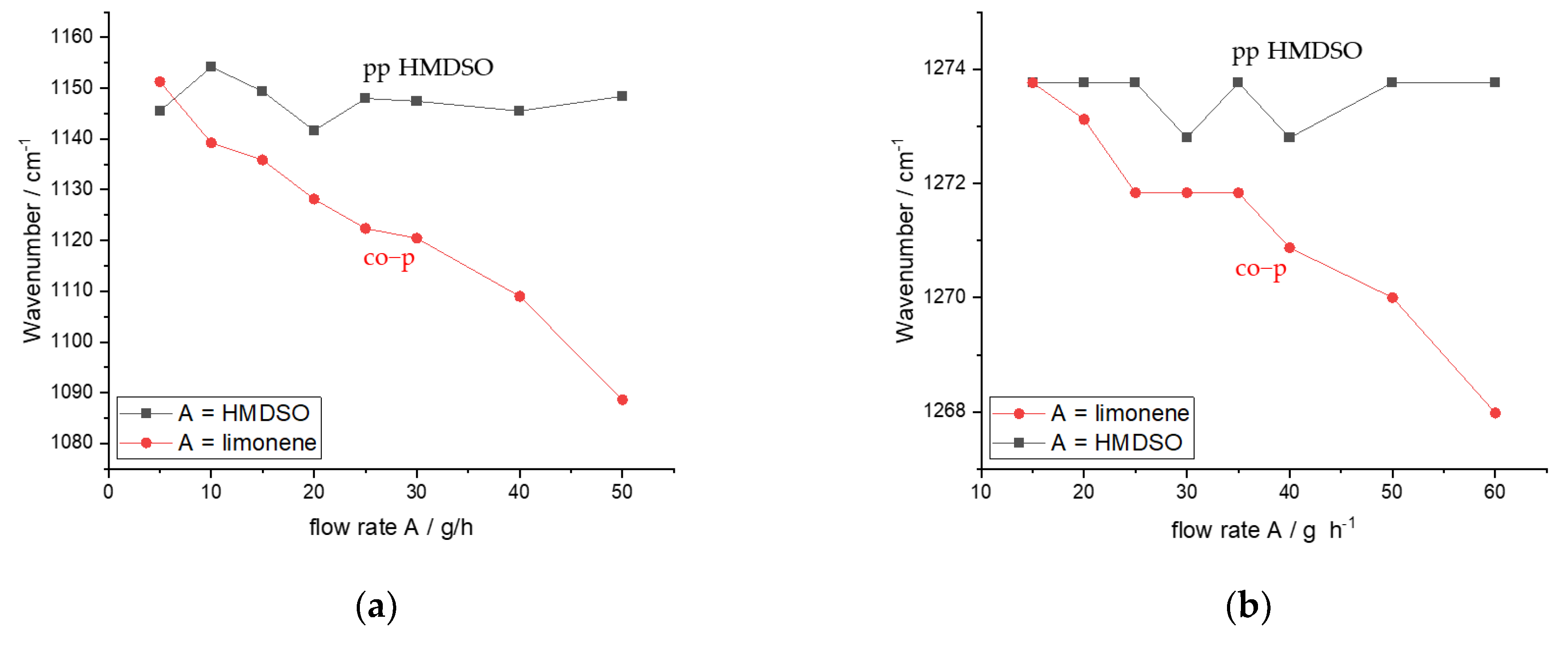
3.2. Effects of Co-Polymerization on the Structure of the Siloxane Network

The ability to finely tune the Si-O-Si network structure is important to improve plasma coating properties like flexibility, stability or porosity. For this purpose, co-p was deposited at different flow rates of lim and analyzed by FTIR with respect to the siloxane network structure. Figure 3a shows the FTIR analysis of the Si-O-Si stretching mode for homo-polymerized HMDSO and when HMDSO and lim are co-polymerized. The graph shows the peak maximum of the Si-O-Si stretching mode of the pp HMDSO as a function of HMDSO flow rate (in black) and of the co-p as a function of lim flow rate (in red). The absorption of the asymmetric stretching mode of Si-O-Si is in the range of 1000 to 1200 cm−1. For pp HMDSO (black curve) we observe the absorption maximum centered around 1150 cm−1 and no shift with increasing HMDSO flow rate. This indicates that with increasing HMDSO flow rate, the Si-O-Si bond angle remains constant and therefore also the neighboring atoms of Si do not change. In contrast, the spectral position of the Si-O-Si stretching mode of the co-p (red curve) shifts from 1150 cm−1 to 1088 cm−1 with increasing flow rate of lim. This indicates that the co-p tends to a “silicon suboxide network” where the change in Si-O-Si network structure is related to a high number of carbon groups bonded to the Si atom [30]. A high coordination of Si atoms with C atoms is expected when the fragmentation of HMDSO is low. Very likely the addition of lim limits the fragmentation of HMDSO, causing the incorporation of only weakly fragmented HMDSO components into the co-p and the red shift of the IR absorption. In addition, a higher proportion of lim in the precursor mixture increases the probability of reactions of Si-O fragments from HMDSO with carbon fragments of lim.
Therefore, two processes can lead to the observed red shift of the Si-O-Si mode: (a) the reaction of lim fragments with an HMDSO fragment (C incorporation); and (b) the weaker fragmentation of HMDSO (HMDSO retention). To analyze the contribution of both processes, we investigated the fragmentation of HMDSO by studying the absorption at 1270 cm−1.
The FTIR absorption around 1270 cm−1 arises from the symmetric bending mode of Si-(CH3)(x=1–3) which is sensitive to the number of methyl groups bonded to the silicon atom. At a low number of methyl groups, the absorption band shifts to higher wavenumbers [39]. We take the position of the Si-(CH3)x(x=1–3) stretching mode as marker for the degree of fragmentation that the HMDSO molecule experiences in the plasma. A high number of methyl groups attached to the Si means that HMDSO was deposited in a structure-preserving way, while a low number of methyl groups corresponds to a strong fragmentation of HMDSO. Figure 3b shows the FTIR peak maximum of the Si-(CH3)x(=1–3) stretching mode of pp HMDSO with increasing HMDSO flow rate (in black/square) and of the co-p with increasing lim flow rate (in red/ circle). The absorption maximum for pp HMDSO does not shift with increasing HMDSO flow rates and is constant between 1274 and 1273 cm−1. This shows that the selected deposition conditions favor strong fragmentation. In contrast, the absorption maximum of the Si-(CH3)x (x=1–3) bending mode of the co-p shifts from 1274 cm−1 with increasing lim flow rate to 1268 cm−1. This is a strong indication that lim limits the fragmentation of HMDSO. The experiment was designed in such a way as to vary only one parameter, namely the monomer flow rate of lim. As a consequence, the total amount of monomer changes in the afterglow, thereby reducing the amount of plasma energy per monomer molecule. This is an additional factor that affects the fragmentation pathways and could have an impact on the results, as has been observed in [42].
The FTIR analysis of the Si-O-Si and Si-(CH3)x(x=1–3) stretching mode is confirmed by the XPS analysis of the Si 2p peaks in the XPS high-resolution spectra. In Figure 4 the Si 2p high-resolution XPS spectra of pp HMDSO and of co-p are shown. For the pp HMDSO the Si 2p peak maximum is centered at 103.4 eV, indicating a high oxygen coordination of the Si atom [43]. For the co-p, the Si 2p peak shifts to a lower binding energy at 102.9 eV, indicative of a higher coordination with carbon atoms and a weaker fragmentation of the HMDSO precursor [43].
In summary, the spectroscopic data (both XPS and FTIR) seem to indicate that co-polymerization with lim leads to a weaker fragmentation of HMDSO which results in a Si-O-Si network with “silicon suboxide network” structure and a high coordination of the silicon atoms with methyl groups. In the coating formation, the incorporation of lim fragments into the pp seems to be of less importance compared to the weaker fragmentation of HMDSO and is not the main reaction mechanism for the silicone-bound carbon atoms.

3.3. Individual Contribution of HMDSO and Lim to the Formation of the Co-p

The FT-IR spectrum of the co-p (Figure 2) shows that fragments of both precursors are found in the co-p. To study to which degree both precursors contribute individually to the plasma synthesis of the co-p, the chemical composition of the coatings was analyzed by XPS. Table 1 shows the XPS analysis of the atomic composition of the coatings for homo-polymerization of HMDSO and lim as well as co-polymerization of both precursors. The monomer flow rate was 10 g∙h−1 in each case, also for the co-p. The pp HMDSO coating contains 28 at.-% Si and 25 at.-% C, reflecting the siloxane nature of the precursor. The pp lim coating contains nearly no Si and 72 at.-% C. For the co-p we find an atomic concentration of 17 at.-% Si and 43 at.-% C.
Table 1 also shows the calculated (theoretical) value for atomic composition when each precursor would contribute arithmetically equal to the co-p. It can be seen that the experimentally observed Si and O atomic concentration in the co-p are higher than the theoretically calculated value. Consequently, the C atomic concentration in the co-p is lower by 5.6% if both precursors would contribute equally to the coating composition.
The XPS analysis indicates that the HMDSO precursor and its fragments or reaction products are more strongly incorporated in the co-p than those of lim. This could be attributed to a more efficient fragmentation/excitation of HMDSO compared to lim resulting in a larger number of HMDSO fragments in the coating formation processes. In addition, a higher reactivity of the fragments towards thin coating formation can explain this result. A higher sticking coefficient of Si fragment than for C fragment has been reported in [44,45]. Another explanation could also be that the etching of C-rich features is higher than for Si-rich features in the co-polymerization process, as can be assumed from published etch rates [46].
The higher fraction of HMDSO in the co-p cannot be explained by the different number of molecules that are fed into the plasma of the two precursors since identical mass flow rates were chosen in our experiments. The effect is even more prominent, since at a mass flow of 10 g∙h−1 the molar flow rate of HMDSO is 60 mmol∙h−1, which is lower than lim with 73 mmol∙h−1. Accordingly, the HMDSO fraction in co-p should be even lower if both precursors would contribute equally to the coating growth.
To elucidate the relative contribution to coating formation of each monomer in more detail, the deposition rates for homo-plasma polymerization of HMDSO and lim were compared with the co-polymerization process at different monomer flow rates. Figure 5 compares the coating thickness when homo-polymerizing the monomers as a function of monomer flow rate. Since the deposition time was equal in all experiments, the coating thickness is a direct measure of the deposition rate. It can be observed that for the pp HMDSO coatings (red curve), the coating thickness increases with increasing monomer flow rates as is well known [4]. In contrast, the coating thickness for pp lim (blue curve) remains constant with increasing monomer flow rate and is much lower than for HMDSO. Following the ideas proposed by Yasuda and Becker originally developed for low-pressure plasma polymerization [15,47] it can be concluded in a simple approximation that the HMDSO deposition occurs in the monomer-deficient regime, where increasing the monomer flow rate increases the deposition rate. In contrast, the deposition of pp lim appears to be limited by insufficient plasma energy. This would also be in agreement with the observation of droplet formation for flow rates > 50 g∙h−1 of lim.
The fact that the deposition rate of HMDSO is much higher than for lim at identical mass flow rates is in agreement with the conclusion from the XPS analysis about the contribution of each precursor in the coating growth of the co-p. A nearly constant coating thickness is also observed when HMDSO and lim are co-polymerized at a fixed flow of HMDSO of 10 g∙h−1 and increasing flow rate for lim (black curve in Figure 5). This is the same behavior observed for the homo-polymerization of lim and the same explanation is likely valid here.
A further comparison of the different coating thicknesses of pp HMDSO, pp lim and co-p shows an interesting result. At a flow rate of 10 g∙h−1, the coating thickness is 97 nm for pp HMDSO and 48 nm for pp lim. The co-p at the same flow rates (10 g∙h−1 each for HMDSO and lim) has a thickness of only 55 nm. This experimental value is significantly lower than the calculated theoretical sum of the coating thickness of 145 nm obtained by adding the individual thicknesses of both precursors.
We explain this observation with the fact that the organic precursor very likely limits the coating growth by weakening HMDSO fragmentation and hindering oxidation so that Si-O-Si bonds cannot be formed. The weaker fragmentation of HMDSO due to co-polymerization was discussed in Section 3.2 and in particular shown in Figure 3b. The surprisingly low coating thickness of the co-p could also be related to a change of density (different networks) in the plasma polymers. However, it seems unlikely that the discussed difference in coating thickness can be explained by this, since the density change probably does not exceed 20% [48].
Despite the fact that increasing the flow rate of lim in the co-polymerization does not lead to an increase in the coating growth rate, we have indications that the chemical layer composition and structure of the co-p are nevertheless affected by the mass flow of lim. This is shown in Figure 6, where we performed a semi-quantitative analysis of the FTIR spectra of the co-p obtained at different lim flow rates and at a constant HMDSO flow of 10 g∙h−1. For this analysis, the relative amount of methyl CH3, nitro NO2 and carbonyl C=O groups in the co-p are compared. To do this, we divide the absorption peak maximum intensity in the spectra of the co-p of the stretching modes attributed to CH3, NO2 and C=O, respectively, by the maximum peak intensity of the Si-O-Si stretching mode. The corresponding stretching modes are at a position of 1380 cm−1 for CH3, for NO2 at 1550 cm−1, for C=O at 1710 cm−1 and for Si-O-Si at around 1100 cm−1. We take the signal intensity of the Si-O-Si group as a measure of the HMDSO contribution and the intensity of CH3, NO2 and C=O as a measure of the lim contribution to the co-p. This is permissible since the chosen absorption positions for the Si-O-Si, CH3, NO2 and C=O groups can be assigned unequivocally to the respective precursor, as the comparison of the FTIR spectra in Figure 2 shows. (Choosing the bending mode for aliphatic CH3 groups at 1380 cm−1 for this analysis allows us to assign this group exclusively to lim, because the CH3 groups bonded to the Si atom in HMDSO are red shifted to 1409 cm−1 (cf. Figure 1)).
Figure 6 shows that the ratios of CH3/Si-O-Si, C=O/Si-O-Si and NO2/Si-O-Si increase with increasing lim flow rate. This indicates that in the co-p with increasing lim flow rate the fraction of lim increases compared to HMDSO. This is surprising because the coating thickness of the co-p remains constant with the increasing flow rate of lim.
However, if the coating thickness is constant, the lim fraction in the co-p can only increase when the HMDSO fraction simultaneously decreases. We explain the decrease of the HMDSO fraction in the co-p again with the fact that lim affects the reactivity of HMDSO fragments due to weaker fragmentation and recombination with lim fragments. As a consequence, the fraction of HMDSO fragments leading to coating formation of the co-p is reduced.

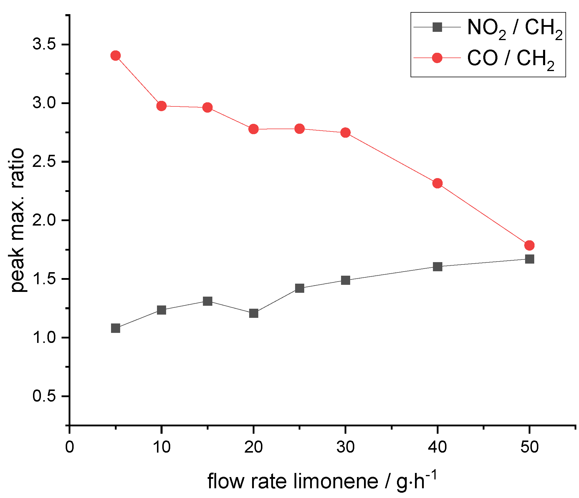
3.4. Role of Post-Plasma and In-Plasma Reactions in the Formation of Nitro and Carbonyl Functional Groups

The deposited co-p has oxygen- and nitrogen-containing groups as shown in the FT-IR spectrum (Figure 2). The role of post-plasma and in-plasma reactions for the formation of these groups will be discussed. To begin with, we focus on the homo-polymerization with lim as precursor. Lim is an aliphatic molecule that, in contrast to the pp lim (c.f. Table 1), does not contain oxygen and nitrogen atoms. Oxygen- and nitrogen-containing groups must therefore be formed by oxidation reactions. In atmospheric pressure plasma polymerization, oxidation can occur by in- or post-plasma reactions. For post-plasma oxidation, the coating is oxidized after deposition by reactions between the coating with atmospheric oxygen or nitrogen. For in-plasma oxidation, reactive oxygen or nitrogen in the plasma (from the ionization gas or by diffusion of air into the plasma plume) react with fragments or activated molecules of the precursor. As was analyzed previously in an OES study, the diffusion of oxygen is minor for the APPJ in this study [20,21].
To understand which role post- and in-plasma reactions have, we analyzed the formation of the oxygen and nitrogen groups in more detail by XPS analysis of the coatings. The coatings were deposited using either N2 or air as ionization gas. If N2 is used as ionization gas, the incorporation of oxygen atoms is mainly possible by post-plasma oxidation, since few reactive oxygen groups are present in the plasma. In contrast, if air is used as the ionization gas, reactive oxygen species are present in the plasma and therefore the formation of oxygen groups is possible via in- and post-plasma oxidation. Table 1 shows the XPS analysis of the atomic composition of homo-polymerization of lim deposited using air or N2 as ionization gas. The carbon content of pp lim N2 of 70 at.-% is almost identical to pp lim of 71 at.-% and also the oxygen content differs only by 3 at.-% points. This indicates that the oxidation processes due to the incorporation of nitrogen and oxygen are similar for both coatings. While for pp lim in- and post-plasma oxidations are possible, for pp lim N2 mainly post-plasma oxidation is possible. The similarity of the oxygen incorporation in the coating suggests that even for the plasma polymerization with air as ionization gas, a significant contribution to the oxygen content in the coating is due to post-plasma oxidation and only a small fraction is from in-plasma reactions.
To validate the hypothesis of the formation of oxygen-containing groups mainly via post-plasma reactions and to understand the formation mechanism of nitrogen-containing groups, the XPS detail spectra were analyzed.
Figure 7 shows the XPS C 1 s high-resolution spectra of homo-polymerization of lim deposited using air or N2 as ionization gas. Moreover, the detail spectra of pp lim and pp lim N2 are quite similar, which indicates that the same carbon-oxygen functions are present with similar relative fraction. The peak at 285.0 eV is assigned to C-C and C-H bonds. The peak with a binding energy of 286.5 eV can be assigned to C-O, at 287.7 eV to O-C-O or C=O, respectively, and at 288.7 eV to COOR [49]. The fraction of C-C and C-H bonds in the C 1 s peak is 57% for pp lim N2 and 60% for pp lim. For pp lim N2, mainly post-plasma oxidation is possible, but still the same functional groups are formed with similar content. The qualitative and quantitative similarity of the C 1 s detail spectra seems to indicate that the carbon-oxygen groups are formed by a similar formation mechanism via post-plasma reactions. This appears to be true even when air is used as ionization gas. The relative content of ca. 5% of COOR groups in the pp lim N2 shows that even these strongly oxidized groups can be formed by post-plasma oxidation.
Figure 8 shows the N 1 s XPS detail spectra of lim deposited using air or N2 as ionization gas. Both spectra for pp lim and pp lim N2 have a broad peak in the range from 398 to 402 eV. This range can be assigned to numerous nitrogen-containing groups such as amide, amine, nitrile, imine, oxime, etc. [50,51]. The peaks at a higher binding energy > 402 eV are characteristic for strongly oxidized nitrogen compounds. The signal at a binding energy of 406 eV can be assigned to a NO2 group and at 408 eV to a NO3 group [51]. The relative fraction of NO2 and NO3 groups in comparison to less oxidized nitrogen compounds is significantly higher for pp lim (49%) than for pp lim N2 (5%). The higher fraction of NO2 and NO3 in pp lim can be related to the different ionization gases. Only when air is used as the ionization gas, nitrogen oxides are present in the plasma as detected by OES [52] This probably explains the high NO2 and NO3 content in pp lim which becomes incorporated by in-plasma reactions. While in-plasma reactions seem to be mostly relevant for NO2/NO3 formation for pp lim, for pp lim N2 it could be in-plasma reactions (from oxygen diffusion or impurities) or post-plasma reactions.
PP lim and pp lim N2 have a comparable tendency to incorporate carbon-oxygen groups via post-oxidation; therefore, it would also be expected for the formation of NO2 and NO3 groups. Since this is not determined, it appears reasonable that for pp lim N2 post-plasma reactions are not likely and therefore impurities and minimal diffusion of oxygen lead to the in-plasma formation of NO2/NO3. The qualitative and quantitative dissimilarity of the peak at 408–404 eV for pp lim is then related to the different oxygen concentrations in the plasma.
In summary, for the homo-polymerization of lim, post-plasma reactions seem to be important for oxygen uptake and in-plasma reactions for nitrogen uptake.
Now we will focus on the role of in-plasma and post-plasma reactions in the copolymerization process. Specifically, we study the formation of the C=O and the NO2 groups in the co-p.
For this purpose, the FTIR spectra of the co-p deposited with a varying lim flow rate were analyzed with respect to the relative amount of NO2 and C=O (Figure 9). Based on the analysis above, we took the absorption feature of the stretching mode of NO2 at 1550 cm−1 as a marker for the in-plasma reactions and those of C=O at 1710 cm−1 as a marker for post-plasma reactions. The absorption of CH3 at 1380 cm−1 is taken as a marker for the non-oxidized groups. The NO2 and C=O absorption intensity is referenced to the CH3 group. This is a simple attempt to understand the influence of the lim flow rate on the in-plasma and post-plasma reactions. Figure 9 shows a decreasing C=O/CH3 ratio with increasing lim flow rate. This is explained by a decrease in C=O content in the coating by the fact that at a high mass flow rate, less plasma energy per molecule is available. As a result, there are less reactive species (e.g., radicals) in the newly formed plasma co-p, which tend to post-oxidize and to form C=O groups. For the in-plasma formation of NO2 groups, an opposite trend compared to the C=O groups is observed. The NO2/CH3 ratio (black curve) increases with the increasing flow rate of lim. This can be explained by the fact that the NO2 groups are formed by in-plasma reactions and the energy-demanding formation of radical sites in the coating for post-plasma reactions is of less importance. We attribute the increase in NO2 fraction to the fact that at high lim flow rates the plasma energy per molecule is lower, which can reduce the decomposition and further oxidation of the reactive NO2 group.

4. Conclusions and Summary

Plasma co-polymerization with an organosilicon (HMDSO) and organic (lim) precursor using an APPJ operating with air was investigated for the first time. The co-p contains characteristic functional groups arising from both precursors. The functional groups of the co-p are C=O, NO2/3, siloxane and aliphatic groups. We observed that in co-polymerization with an APPJ, the flow rate of lim is an important parameter for tuning the structure and composition of the co-p. The effect of co-polymerization on the formation mechanism of the functional groups was studied in more detail.
XPS and FTIR analysis indicate that the addition of lim leads to a higher proportion of carbon-containing groups bonded to the Si atoms. This is related to the incorporation of lim fragments into the siloxane network and weaker fragmentation of HMDSO. The strong shift of the Si-(CH3)x(x=1–3) stretching mode with increasing flow rate of lim indicates that the weaker fragmentation of HMDSO is the main mechanism for the increase of silicon-bonded carbon atoms. Moreover, the Si-O-Si stretching mode of the co-p is red shifted at a high flow rate of lim in comparison to homo-polymerized HMDSO. This indicates that the addition of lim during co-polymerization results in a “silicon suboxide network”-like structure instead of a “cage”-like structure obtained when HMDSO is homo-polymerized.
The FTIR and XPS analysis of the formation mechanism of C=O and NO2/3 groups show that the C=O groups are mainly formed by post-plasma reaction and the NO2/3 groups are mainly formed by in-plasma reactions. The relative role of in- and post-plasma reactions can also be influenced by the lim flow rate during co-polymerization, to favor the formation of NO2 or C=O groups.
The post-plasma reactions have a significant influence on the composition of the coating, as shown in particular by the high oxygen content of 23 at.-% of pp lim N2. Post-plasma reactions occur between the coating and the surrounding atmosphere. This could indicate that a more precise control of the atmospheric conditions might be beneficial for atmospheric plasma coating processes in industrial applications. Further studies are needed to better understand the influence of different atmospheric conditions such as temperature and humidity.
The study shows that co-polymerization with an APPJ allows one to synthesize coatings with functional groups originating from an organic and an organosilicon (inorganic) precursor. The flow rate of the organic precursor in the mix was found to be very effective in tuning the network structure and the quantity and quality of functional groups such as NO2/3 or C=O. Such deposition processes might therefore be of particular interest for the synthesis of flexible barrier coatings with good adhesion properties.

Author Contributions

Conceptualization, G.W. and U.L.; methodology, G.W.; validation, G.W.; formal analysis, G.W.; investigation, G.W.; resources, U.L. and B.M.; data curation, G.W.; writing—original draft preparation, G.W.; writing—review and editing, U.L. and B.M.; visualization, G.W.; supervision, U.L.; project administration, G.W., U.L. and B.M.; funding acquisition, U.L. and B.M. All authors have read and agreed to the published version of the manuscript.

Funding

This research received no external funding.

Institutional Review Board Statement

Not applicable.

Informed Consent Statement

Not applicable.

Data Availability Statement

Not applicable.

Conflicts of Interest

The authors declare no conflict of interest.

References

  1. Fanelli, F.; Fracassi, F. Atmospheric pressure non-equilibrium plasma jet technology: General features, specificities and applications in surface processing of materials. Surf. Coat. Technol. 2017, 322, 174–201. [Google Scholar] [CrossRef]
  2. Merche, D.; Vandencasteele, N.; Reniers, F. Atmospheric plasmas for thin film deposition: A critical review. Thin Solid Films 2012, 520, 4219–4236. [Google Scholar] [CrossRef]
  3. Penkov, O.V.; Khadem, M.; Lim, W.-S.; Kim, D.-E. A review of recent applications of atmospheric pressure plasma jets for materials processing. J. Coat. Technol. Res. 2015, 12, 225–235. [Google Scholar] [CrossRef]
  4. Lommatzsch, U.; Ihde, J. Plasma Polymerization of HMDSO with an Atmospheric Pressure Plasma Jet for Corrosion Protection of Aluminum and Low-Adhesion Surfaces. Plasma Process. Polym. 2009, 6, 642–648. [Google Scholar] [CrossRef]
  5. Foest, R.; Kindel, E.; Ohl, A.; Stieber, M.; Weltmann, K.-D. Non-thermal atmospheric pressure discharges for surface modification. Plasma Phys. Control. Fusion 2005, 47, B525–B536. [Google Scholar] [CrossRef]
  6. Bringmann, P.; Rohr, O.; Gammel, F.J.; Jansen, I. Atmospheric Pressure Plasma Deposition of Adhesion Promotion Layers on Aluminium. Plasma Process. Polym. 2009, 6, S496–S502. [Google Scholar] [CrossRef]
  7. Pulpytel, J.; Kumar, V.; Peng, P.; Micheli, V.; Laidani, N.; Arefi-Khonsari, F. Deposition of Organosilicon Coatings by a Non-Equilibrium Atmospheric Pressure Plasma Jet: Design, Analysis and Macroscopic Scaling Law of the Process. Plasma Process. Polym. 2011, 8, 664–675. [Google Scholar] [CrossRef]
  8. Schäfer, J.; Foest, R.; Sigeneger, F.; Loffhagen, D.; Weltmann, K.-D.; Martens, U.; Hippler, R. Study of thin Film Formation From Silicon-Containing Precursors Produced by an RF Non-Thermal Plasma Jet at Atmospheric Pressure. Contrib. Plasma Phys. 2012, 52, 872–880. [Google Scholar] [CrossRef]
  9. Schäfer, J.; Foest, R.; Quade, A.; Ohl, A.; Weltmann, K.-D. Chemical Composition of SiO x Films Deposited by an Atmospheric Pressure Plasma Jet (APPJ). Plasma Process. Polym. 2009, 6, S519–S524. [Google Scholar] [CrossRef]
  10. Ramamoorthy, A.; Rahman, M.; Mooney, D.A.; Don MacElroy, J.M.; Dowling, D.P. The Influence of Process Parameters on Chemistry, Roughness and Morphology of Siloxane Films Deposited by an Atmospheric Plasma Jet System. Plasma Process. Polym. 2009, 6, S530–S536. [Google Scholar] [CrossRef]
  11. Castro, A.H.R.; Kodaira, F.V.; Prysiazhnyi, V.; Mota, R.P.; Kostov, K.G. Deposition of thin films using argon/acetylene atmospheric pressure plasma jet. Surf. Coat. Technol. 2017, 312, 13–18. [Google Scholar] [CrossRef] [Green Version]
  12. Marcinauskas, L.; Grigonis, A.; Valatkevičius, P. Deposition of carbon structures at atmospheric pressure by plasma jet. J. Optoelectron. Adv. Mater. 2010, 12, 829. [Google Scholar]
  13. Van Vrekhem, S.; Morent, R.; de Geyter, N. Deposition of a PMMA coating with an atmospheric pressure plasma jet. J. Coat. Technol. Res. 2018, 15, 679–690. [Google Scholar] [CrossRef]
  14. Yan, J.; Hosoi, K.; Kuroda, S. Polymerization of Maleic Anhydride Induced by Non-Equilibrium Atmospheric Pressure Argon Plasma. AMM 2014, 670–671, 244–248. [Google Scholar] [CrossRef]
  15. Yasuda, H. Glow discharge polymerization. In Thin Film Processes; Academic Press: San Diego, CA, USA, 1978. [Google Scholar]
  16. Kakaroglou, A.; Scheltjens, G.; Nisol, B.; de Graeve, I.; van Assche, G.; van Mele, B.; Willem, R.; Biesemanns, M.; Reniers, F.; Terryn, H. Deposition and Characterisation of Plasma Polymerised Allyl Methacrylate Based Coatings. Plasma Process. Polym. 2012, 9, 799–807. [Google Scholar] [CrossRef]
  17. Petersen, J.; Becker, C.; Fouquet, T.; Addiego, F.; Toniazzo, V.; Dinia, A.; Ruch, D. Nano-ordered thin films achieved by soft atmospheric plasma polymerization. RSC Adv. 2013, 3, 4416. [Google Scholar] [CrossRef]
  18. Petersen, J.; Bechara, R.; Bardon, J.; Fouquet, T.; Ziarelli, F.; Daheron, L.; Ball, V.; Toniazzo, V.; Michel, M.; Dinia, A.; et al. Atmospheric Plasma Deposition Process: A Versatile Tool for the Design of Tunable Siloxanes-Based Plasma Polymer Films. Plasma Process. Polym. 2011, 8, 895–903. [Google Scholar] [CrossRef]
  19. Friedrich, J. Mechanisms of Plasma Polymerization—Reviewed from a Chemical Point of View. Plasma Process. Polym. 2011, 8, 783–802. [Google Scholar] [CrossRef]
  20. Lommatzsch, U.; Pasedag, D.; Baalmann, A.; Ellinghorst, G.; Wagner, H.-E. Atmospheric Pressure Plasma Jet Treatment of Polyethylene Surfaces for Adhesion Improvement. Plasma Process. Polym. 2007, 4, S1041–S1045. [Google Scholar] [CrossRef]
  21. Thomas, M.; von Hausen, M.; Klages, C.-P.; Baumhof, P. Generation of stable coatings with carboxylic groups by copolymerization of MAA and VTMS using DBD at atmospheric pressure. Plasma Process. Polym. 2007, 4, 475–481. [Google Scholar] [CrossRef]
  22. Marcinauskas, L.; Valinčius, V.; Grigonis, A. Deposition and structure characterization of carbon films prepared at atmospheric pressure by plasma jet. Surf. Coat. Technol. 2011, 205, 71–74. [Google Scholar] [CrossRef]
  23. Han, G.-J.; Chung, S.-N.; Chun, B.-H.; Kim, C.-K.; Oh, K.H.; Cho, B.-H. 1,3-Butadiene as an Adhesion Promoter Between Composite Resin and Dental Ceramic in a Dielectric Barrier Discharge Jet. Plasma Chem. Plasma Process. 2013, 33, 539–551. [Google Scholar] [CrossRef]
  24. Ben Said, S.; Arefi-Khonsari, F.; Pulpytel, J. Plasma Polymerization of 3-Aminopropyltrietoxysilane (APTES) by Open-Air Atmospheric Arc Plasma Jet for In-Line Treatments. Plasma Process. Polym. 2016, 13, 1025–1035. [Google Scholar] [CrossRef]
  25. Alba-Elías, F.; Sainz-García, E.; González-Marcos, A.; Ordieres-Meré, J. Tribological behavior of plasma-polymerized aminopropyltriethoxysilane films deposited on thermoplastic elastomers substrates. Thin Solid Films 2013, 540, 125–134. [Google Scholar] [CrossRef]
  26. Grill, A. Porous pSiCOH Ultralow- k Dielectrics for Chip Interconnects Prepared by PECVD. Annu. Rev. Mater. Res. 2009, 39, 49–69. [Google Scholar] [CrossRef]
  27. Ding, Z.-J.; Ding, S.-J.; Zhang, W. Plasma enhanced chemical vapor deposition ultralow dielectric constant films using triethoxymethylsilane and limonene as precursors. In Proceedings of the 2014 12th IEEE International Conference on Solid-State and Integrated Circuit Technology (ICSICT), Guilin, China, 28–31 October 2014; pp. 1–3. [Google Scholar]
  28. Cho, S.-J.; Bae, I.-S.; Boo, J.-H.; Lee, S.; Jung, D. The Optical and Mechanical Properties of Toluene-TEOS Hybrid Plasma-Polymer Thin Films Deposited by PECVD. J. Korean Phy. Soc. 2009, 55, 1780–1784. [Google Scholar] [CrossRef]
  29. Beck, A.J.; Jones, F.R.; Short, R.D. Plasma copolymerization as a route to the fabrication of new surfaces with controlled amounts of specific chemical functionality. Polymer 1996, 37, 5537–5539. [Google Scholar] [CrossRef]
  30. Grill, A.; Neumayer, D.A. Structure of low dielectric constant to extreme low dielectric constant SiCOH films: Fourier transform infrared spectroscopy characterization. J. Appl. Phys. 2003, 94, 6697–6707. [Google Scholar] [CrossRef]
  31. Manakhov, A.; Moreno-Couranjou, M.; Choquet, P.; Boscher, D.; Pireaux, J.-J. Diene functionalisation of atmospheric plasma copolymer thin films. Surf. Coat. Technol. 2011, 205, 466–469. [Google Scholar] [CrossRef]
  32. Abessolo Ondo, D.; Loyer, F.; Chemin, J.-B.; Bulou, S.; Choquet, P.; Boscher, N.D. Atmospheric plasma oxidative polymerization of ethylene dioxythiophene (EDOT) for the large-scale preparation of highly transparent conducting thin films. Plasma Process. Polym. 2018, 15, 1700172. [Google Scholar] [CrossRef] [Green Version]
  33. Makhneva, E.; Farka, Z.; Pastucha, M.; Obrusník, A.; Horáčková, V.; Skládal, P.; Zajíčková, L. Maleic anhydride and acetylene plasma copolymer surfaces for SPR immunosensing. Anal. Bioanal. Chem. 2019, 411, 7689–7697. [Google Scholar] [CrossRef] [PubMed]
  34. Manakhov, A.; Michlíček, M.; Nečas, D.; Polčák, J.; Makhneva, E.; Eliáš, M.; Zajíčková, L. Carboxyl-rich coatings deposited by atmospheric plasma co-polymerization of maleic anhydride and acetylene. Surf. Coat. Technol. 2016, 295, 37–45. [Google Scholar] [CrossRef] [Green Version]
  35. Manakhov, A.; Moreno-Couranjou, M.; Choquet, P.; Boscher, D.; Pireaux, J.-J. Atmospheric Pressure Pulsed Plasma Copolymerisation of Maleic Anhydride and Vinyltrimethoxysilane: Influence of Electrical Parameters on Chemistry, Morphology and Deposition Rate of the Coatings. Plasma Process. Polym. 2012, 9, 435–445. [Google Scholar] [CrossRef]
  36. Jang, H.J.; Park, C.-S.; Jung, E.Y.; Bae, G.T.; Shin, B.J.; Tae, H.-S. Synthesis and Properties of Thiophene and Aniline Copolymer Using Atmospheric Pressure Plasma Jets Copolymerization Technique. Polymers 2020, 12, 2225. [Google Scholar] [CrossRef]
  37. Ben Salem, D.; Carton, O.; Fakhouri, H.; Pulpytel, J.; Arefi-Khonsari, F. Deposition of Water Stable Plasma Polymerized Acrylic Acid/MBA Organic Coatings by Atmospheric Pressure Air Plasma Jet. Plasma Process. Polym. 2014, 11, 269–278. [Google Scholar] [CrossRef]
  38. Hossain, M.M.; Trinh, Q.H.; Nguyen, D.B.; Sudhakaran, M.S.P.; Mok, Y.S. Robust hydrophobic coating on glass surface by an atmospheric-pressure plasma jet for plasma-polymerisation of hexamethyldisiloxane conjugated with (3-aminopropyl) triethoxysilane. Surf. Eng. 2019, 35, 466–475. [Google Scholar] [CrossRef]
  39. Gilliam, M.A.; Farhat, S.A.; Garner, G.E.; Stubbs, B.P.; Peterson, B.B. Characterization of the deposition behavior and changes in bonding structures of hexamethyldisiloxane and decamethylcyclopentasiloxane atmospheric plasma-deposited films*. Plasma Process. Polym. 2019, 16, e1900024. [Google Scholar] [CrossRef]
  40. Grill, A. Plasma enhanced chemical vapor deposited SiCOH dielectrics: From low-k to extreme low-k interconnect materials. J. Appl. Phys. 2003, 93, 1785–1790. [Google Scholar] [CrossRef]
  41. Spektroskopische Methoden in der Organischen Chemie, 7th ed.; Hesse, M.; Meier, H.; Zeeh, B. (Eds.) Thieme: Stuttgart, Germany, 2005. [Google Scholar]
  42. Prysiazhnyi, V.; Kratochvil, J.; Stranak, V. Tailored wettability of plasma polymers made of C–F, C–H, and N–H. Plasma Process. Polym. 2019, 16, 1900076. [Google Scholar] [CrossRef]
  43. Kim, C.Y.; Kim, S.H.; Navamathavan, R.; Choi, C.K.; Jeung, W.Y. Characteristics of low-k SiOC(–H) films deposited at various substrate temperature by PECVD using DMDMS/O2 precursor. Thin Solid Films 2007, 516, 340–344. [Google Scholar] [CrossRef]
  44. Hegemann, D.; Nisol, B.; Gaiser, S.; Watson, S.; Wertheimer, M.R. Energy conversion efficiency in low- and atmospheric-pressure plasma polymerization processes with hydrocarbons. Phys. Chem. Chem. Phys. 2019, 21, 8698–8708. [Google Scholar] [CrossRef] [PubMed]
  45. Enache, I.; Caquineau, H.; Gherardi, N.; Paulmier, T.; Maechler, L.; Massines, F. Transport Phenomena in an Atmospheric-Pressure Townsend Discharge Fed by N2/N2O/HMDSO Mixtures. Plasma Process. Polym. 2007, 4, 806–814. [Google Scholar] [CrossRef]
  46. Jeong, J.Y.; Babayan, S.E.; Tu, V.J.; Park, J.; Henins, I.; Hicks, R.F.; Selwyn, G.S. Etching materials with an atmospheric-pressure plasma jet. Plasma Sources Sci. Technol. 1998, 7, 282–285. [Google Scholar] [CrossRef]
  47. Wissenschaftliche Veröffentlichungen aus dem Siemens-Konzern; Erster Band 1920–1922; Becker, H.; Boedeker, K.; von Buol, H.; Ebeling, A.; Engelhardt, V.; Erlwein, G.; Fellinger, R.; Feuerlein, O.; Franke, A.; Friese, M.; et al. (Eds.) Springer: Berlin/Heidelberg, Germany, 1922. [Google Scholar]
  48. Hashmi, S. (Ed.) Comprehensive Materials Processing; Elsevier: Amsterdam, The Netherlands, 2014; Volume 13. [Google Scholar]
  49. Yumitori, S. Correlation of C1s chemical state intensities with the O1s intensity in the XPS analysis of anodically oxidized glass-like carbon samples. J. Mater. Sci. 2000, 35, 139–146. [Google Scholar] [CrossRef]
  50. Truica-Marasescu, F.; Wertheimer, M.R. Nitrogen-Rich Plasma-Polymer Films for Biomedical Applications. Plasma Process. Polym. 2008, 5, 44–57. [Google Scholar] [CrossRef]
  51. Finke, B.; Schröder, K.; Ohl, A. Surface Radical Detection on NH3-Plasma Treated Polymer Surfaces Using the Radical Scavenger NO. Plasma Process. Polym. 2008, 5, 386–396. [Google Scholar] [CrossRef]
  52. Schmidt-Bleker, A.; Bansemer, R.; Reuter, S. How to produce an NOx- instead of Ox-based chemistry with a cold atmospheric plasma jet. Plasma Process. Polym. 2016, 13, 1120–1127. [Google Scholar] [CrossRef]
Figure 1. (a) Schematic of the plasma jet system for deposition. (b) Chemical structure of HMDSO and lim.
Plasma 05 00004 g001
Figure 2. FTIR spectra of the pp with precursors: (a) lim (10 g∙h−1); (b) co-p (10 g∙h−1 HMDSO and 10 g∙h−1 lim); (c) HMDSO (10 g∙h−1). The FTIR spectra depict the coatings that were obtained with identical process parameters resulting in the individual coating thicknesses as indicated. A significant influence on the FTIR spectra is not expected for such low coating thicknesses.
Plasma 05 00004 g002
Figure 3. Position of the FTIR absorption maximum of the (a) Si-O-Si; (b) Si-(CH3) Si-(CH3)x(x=1–3) stretching mode of pp HMDSO and co-p. For co-polymerization, the HMDSO flow rate was fixed at 10 g∙h−1.
Plasma 05 00004 g003
Figure 4. Si 2p high-resolution XPS spectra of (a) ppHMDSO (10 g∙h−1); (b) co-p (10 g∙h−1 HMDSO and 10 g∙h−1 lim).
Plasma 05 00004 g004
Figure 5. Coating thickness at different flow rates of homo-polymerization of (blue curve) lim; (red curve) HMDSO; (black curve) co-p of lim and HMDSO (at a constant flow rate of 10 g∙h−1).
Plasma 05 00004 g005
Figure 6. Ratios of peak maxima of FTIR absorption of CH3, CO and NO2 stretching mode divided by Si-O-Si mode at a fixed HMDSO flow rate of 10 g∙h−1 and different limonene flow rates.
Plasma 05 00004 g006
Figure 7. C 1 s high-resolution XPS spectra and percentage of the different binding energies of pp lim (lim flow rate of 10 g h−1) deposited using (a) air; (b) N2 as ionization gases.
Plasma 05 00004 g007
Figure 8. N 1 s high-resolution XPS spectra of pp lim deposited at a lim flow rate of 10 g ∙ h−1 and (a) air and (b) nitrogen as ionization gas.
Plasma 05 00004 g008
Figure 9. Peak maximum ratios of FTIR absorption of CH, C=O and NO2 stretching mode at an HMDSO flow rate of 10 g∙h−1 and different lim flow rates.
Plasma 05 00004 g009
Table 1. XPS data of the chemical composition of pp HMDSO (10 g∙h−1), lim (10 g∙h−1) with air and N2, co-P (10 g∙h−1 HMDSO and 10 g∙h−1 lim) and a theoretical co-p, calculated as the arithmetic mean of pp lim and pp HMDSO.
CoatingXPS Chemical Composition
at.-%
CarbonOxygenSiliconNitrogen
pp HMDSO25.446.128.30.3
co-p42.739.417.40.7
pp lim71.227.10.21.6
pp lim N270.223.20.16.6
theoretical co-p48.336.614.31.0
Publisher’s Note: MDPI stays neutral with regard to jurisdictional claims in published maps and institutional affiliations.

