Review

Zirconia-Based Ceramics Reinforced by Carbon Nanotubes: A Review with Emphasis on Mechanical Properties

1
Department of Materials Science, Energy and Nano-Engineering, Mohammed VI Polytechnic University, Lot 660—Hay Moulay Rachid, Ben Guerir 43150, Morocco
2
Institute of Materials Physics and Engineering, Department of Applied Science and Technology, Politecnico di Torino, 10129 Torino, Italy
*
Authors to whom correspondence should be addressed.
Ceramics 2023, 6(3), 1705-1734; https://doi.org/10.3390/ceramics6030105
Submission received: 23 May 2023 / Revised: 30 June 2023 / Accepted: 1 August 2023 / Published: 6 August 2023
(This article belongs to the Special Issue Ceramic Processing and Sintering, Volume II)

Abstract

:
This review outlines the state of the art, processing techniques, and mechanical testing methods of zirconia (ZrO2)-based composites reinforced by carbon nanotubes (CNTs). The use of CNTs as a secondary phase in a zirconia matrix is motivated by their outstanding crack self-healing ability, the possibility to tailor the desired nano-structural properties, and their exceptional wear behavior. Therefore, a detailed investigation into CNT features has been provided. The debate of using the different Vickers indentation fracture toughness equations to estimate the resistance of crack propagation was critically reviewed according to crack characteristics. Finally, this review particularly highlights the exceptional role of ZrO2-based composites as a promising material owing to their outstanding tribo-mechanical properties.

Graphical Abstract

1. Introduction

Ceramic-matrix composites (CMCs) afford a new generation of technical applications with excellent efficiency due to their great potential and unique properties. CMCs are known to be robust, lightweight, and highly wear-resistant, which makes them a proper class of materials in automotive applications (e.g., oxygen sensors and brake systems), aerospace engineering (e.g., hot structures), and remarkable tribological applications [1,2,3]. Ceramics and their composites have shown great advances in most tribological applications and have replaced metals and conventional materials, such as grey cast iron, in the fabrication of brake systems. High wear resistance combined with a low friction coefficient are desirable for reducing the losses in the movement of rotating parts and increasing the lifetime of components, respectively. A wide range of factors, including the applied load, sliding speed, time of contact, temperature, lubrication, and surface characteristics, such as composition and roughness, influence the wear properties of CMCs.
CMCs also allow for improving the mechanical behavior of conventional polycrystalline ceramics, which typically suffer from high brittleness and low fracture toughness. In general, CMCs are produced from at least one micro-/nano-sized reinforcing/toughening phase embedded in a ceramic matrix [4]. The second phase can be constituted by ceramic micro- or nanoparticles (SiC and Si3N4), nanotubes (e.g., CNTs), nanoplatelets (graphene), or hybrids of these materials.
Niihara et al. were the first to introduce the concept of ceramic nanocomposites in 1991 [5,6,7,8]. Their work mainly dealt with SiC nanoparticles’ incorporation as a second phase in Al2O3, Si3N4, and MgO ceramic matrices. After they reported significant improvements, a series of research works succeeded in incorporating different nanoparticles (e.g., SiC, Si3N4, TiN, TiC, TiO2, and ZrO2) in various ceramic matrices, such as Al2O3, Si3N4, MgO, SiAlON, etc. Reinforcing ceramic matrices with CNTs has gained much interest since the first report by Iijima [9]. Owing to their one-dimensional nanostructure, CNTs provide exceptional mechanical, electrical (107 S/m), and thermal properties (1800–6000 W/mK) compared with nanoparticles [10]. Hence, CNT addition can increase not only ceramic matrix toughness, but is also responsible for the improvement of its functional properties, namely its electrical and thermal properties.
In order to produce ceramic/CNT composites with improved mechanical and functional properties, appropriate interfacial bonding between the ceramic matrix and CNTs and the uniform dispersion of CNTs along the grain boundaries are required. Owing to their high aspect ratio, CNTs tend to agglomerate, leading to stress concentration and, therefore, the overall properties of the composites being decreased. The preparation process and the choice of an appropriate sintering technique play an important role in defining the final mechanical, as well as tribological and functional, properties of composites [6,7].
ZrO2-based nanocomposites are among the most widely investigated and technologically powerful ceramic materials involved in several fields. The important properties of ZrO2, such as its high ionic conductivity, low density, chemical inertness, good wear resistance, high mechanical strength, and stability at high temperatures, have enabled its wide use in a range of challenging structural, tribological, and multifunctional applications [7,11]. Typical applications are designed to withstand harsh environments and to increase the worldwide clean energy demand, either by direct electrochemical power generation, for example, solid-oxide fuel cell (SOFC) devices, or in an indirect way by serving as a thermal barrier coating in engines, thereby ensuring low-cost electrical energy for the customers due to the higher engine efficiency [12]. Other important applications are in the field of load-bearing joint prostheses and dental implants [13], where the mechanical properties play a key role [14].
Yttria-stabilized ZrO2 possesses the advantage of phase transformation from tetragonal to monoclinic under applied stress. This mechanism is usually referred to as transformation toughening in zirconia and occurs as the volume expansion associated with the tetragonal-to-monoclinic transformation produces a stress intensity decrease at the crack tip, thus yielding a dissipation of the energy of the propagating crack. Cracks become self-stopping as, in order to allow crack propagation, both the energy barrier required for phase transformation and that associated with the volume expansion of the transformed material have to be overcome [2,3]. However, monophasic and even stabilized ZrO2 materials still exhibit brittle behavior, which constitutes a major issue [15]. To overcome this drawback, several attempts have been made to further improve the fracture behavior of ZrO2, for example, by introducing a second-phase material, while preserving all the other advantages of the matrix. In this regard, multi-walled carbon nanotube (MWCNT)-reinforced ZrO2 composites are attracting growing interest owing to their crack self-healing ability and the possibility to tailor the desired nano-structural properties. Therefore, to completely benefit from their outstanding properties, a deep understanding of the material’s behavior across the different length scales is required. Although great effort and progress have been made over the past ten years in the investigation of zirconia-based composites, only a few new material systems and novel processing techniques have been proposed. The high-energy ball milling process has been assessed for successfully synthesizing a wide range of nano-structured ceramic powders, including ZrO2. The easy operating principle uses the solid-state reaction at a temperature close to room temperature and affords low cost with an effective preparation process [16]. On the other hand, spark plasma sintering (SPS) has been emphasized by a large number of researchers to show minimal damage to CNTs and high efficiency in sintering nanostructured ceramic-based materials [9]. In this paper, a detailed investigation into the micro-structural features of zirconia composites and CNTs separately, along with presenting the most recently advanced techniques to synthesize zirconia-based composites, such as SPS and high-energy ball milling, is provided. Furthermore, this paper reviews the historical evolution of the most advanced techniques used to test the mechanical properties of ceramic matrix composites, such as hardness, strength, and indentation fracture toughness (IFT).

2. Zirconia Matrix: An Overview
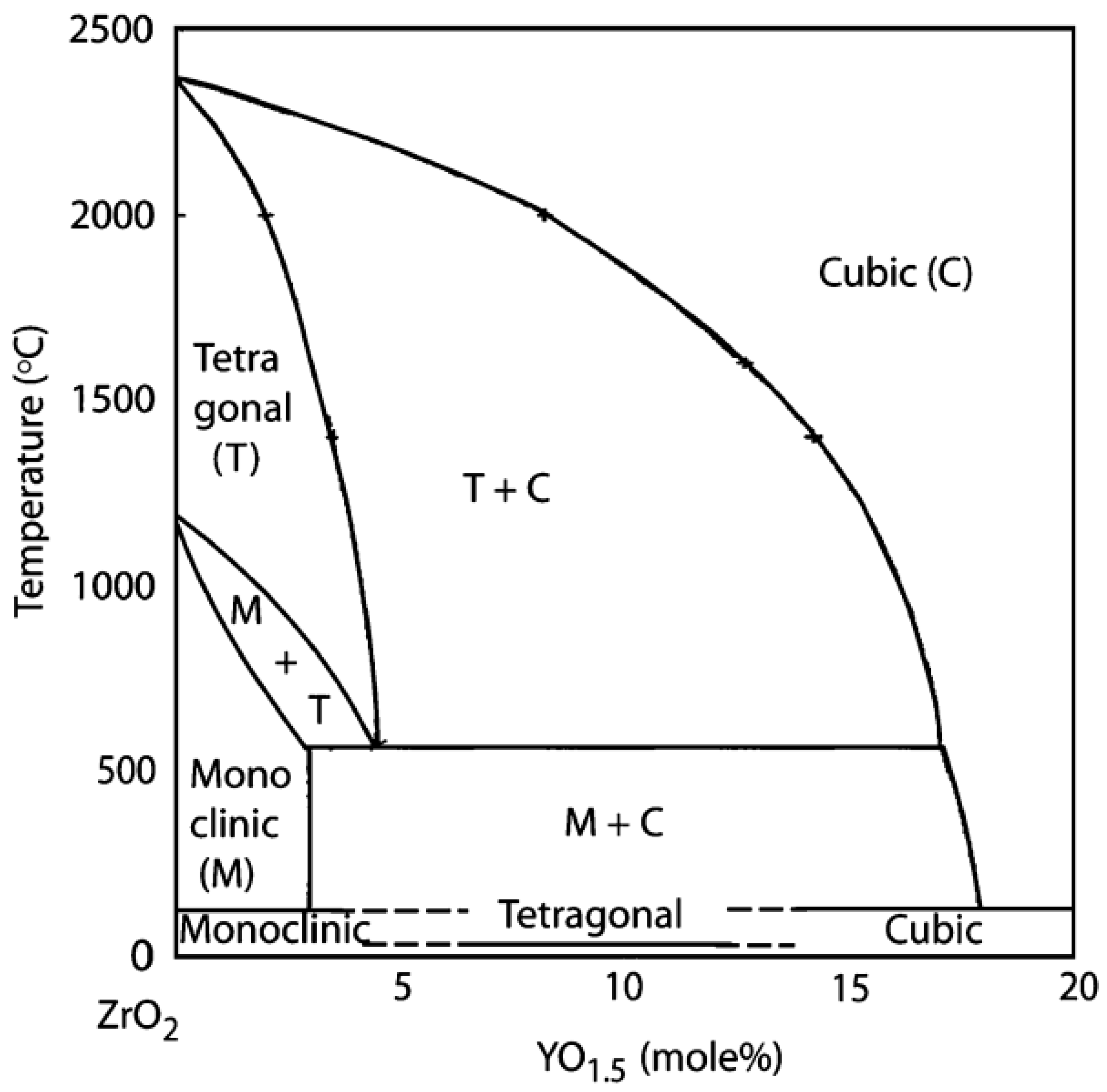
Zirconium dioxide (ZrO2), also named zirconia, is the mineral of baddeleyite and is chemically inert. In its pure form, ZrO2 exhibits a polymorphic configuration and exists in three distinct phases at ambient pressure. The monoclinic phase is stable from room temperature up to 1170 °C. Tetragonal ZrO2 with a distorted fluorite structure is stable at intermediate temperatures between 1170 and 2370 °C, while the cubic fluorite phase is stable at very high temperatures from 2370 °C up to its melting point (2750 °C) [16,17]. The crystal structures of these three zirconia phases are presented in Figure 1, where the large red spheres correspond to oxygen and the small green ones are zirconium. The higher the temperature, the better the symmetry. The phase transition ability makes zirconia one of the most-studied ceramic materials over the last few decades and an important candidate for diverse areas of structural applications [18].
The structure of cubic zirconia can be represented by a face-centered cubic (FCC) structure similar to that of fluorite. The eight oxygen ions occupy the tetrahedral interstitial sites and are surrounded by Zr4+ cations, which occupy the summits of the cube and the centers of each face (Figure 1a). The tetragonal phase of zirconia is represented by a straight prism with rectangular sides (Figure 1b). Similar to the cubic structure, zirconium (Zr) ions are coordinated to eight oxygen atoms, and the oxygen atoms are coordinated to four Zr ions. However, the distorted shape of the tetragonal phase is linked to the alternative oxygen ions’ displacement along the c-axis, resulting in the formation of two tetrahedron plans where one is elongated and rotated by 90° due to the different distances of each of the four oxygen ions from Zr4+ (2.065 and 2.455 Å, respectively) [20]. In its natural form, zirconia exhibits the monoclinic phase at low temperatures known as baddeleyite and contains about 2% HfO2 (hafnium oxide), with high chemical and structural similarity to zirconia. In the monoclinic phase, Zr4+ ions are coordinated to seven oxygen ions residing in tetrahedral interstices (Figure 1c). The Zr ions are coordinated to three and four oxygens at average distances of 2.07 and 2.21 Å, respectively. Therefore, one of the angles (134.3°) differs considerably from the tetrahedral value (109.5°) [21].

2.1. Phase Diagram

Phase transformation from tetragonal to monoclinic occurs at a temperature between 850 and 1000 °C after the processing of pure zirconia and during the post-sintering cooling period [17]. The phase transformation due to polymorphism is associated with high volume expansion (~5–7 vol%), promoting the risk of brittle failure or the apparition of cracks and flaws in the polycrystalline ceramic [22]. Therefore, the manufacture of pure zirconia is unfeasible due to the high risk of catastrophic failure. To retain the tetragonal form at room temperature after sintering, typical oxide dopants are added to pure zirconia, such as yttria (Y2O3), calcium oxide (CaO), and ceria (CeO2). However, yttria is the most commonly employed stabilizing oxide, as lower amounts are needed [23]. The phase diagram of ZrO2/Y2O3 presented in Figure 2 illustrates the stability regions of different phases according to the amount of yttria added to stabilize pure zirconia. It is shown that the reverse phase transition from monoclinic to tetragonal occurring at approximately 1170 °C decreased to <600 °C with the addition of ~4.8 mol% of yttria. The coexistence of a multiphase structure (cubic + tetragonal, cubic + monoclinic, cubic, and tetragonal + monoclinic) is observed in the solid solution regions separated by the single phases. Hence, partially stabilized zirconia (PSZ) with cubic and tetragonal structures as major phases and monoclinic precipitates in small amounts can be produced [24]. These materials are stable at temperatures between 600 and 2000 °C with an yttria content in the range of 3–8 mol% and exhibit exceptional resistance to high thermal shock [21,25,26].
Tetragonal zirconia polycrystals (TZPs), retaining the tetragonal phase at room temperature and formed by a single-phase metastable structure, or fully stabilized zirconia (FSZ) with a fully cubic structure, which is stable at high temperatures with approximately higher yttria contents (>8 mol%), are the most useful states of zirconia [25]. Some studies have claimed that the presence of a small carbon fraction in cubic zirconia composite may boost its stability at room temperature [28]. In fact, TZP materials exhibit good comprehensive mechanical properties at both room and high temperatures, which is mainly attributed to the ferroelastic toughening mechanism, while FSZ is generally employed in electrochemical applications due to its high ionic conductivity [29,30].

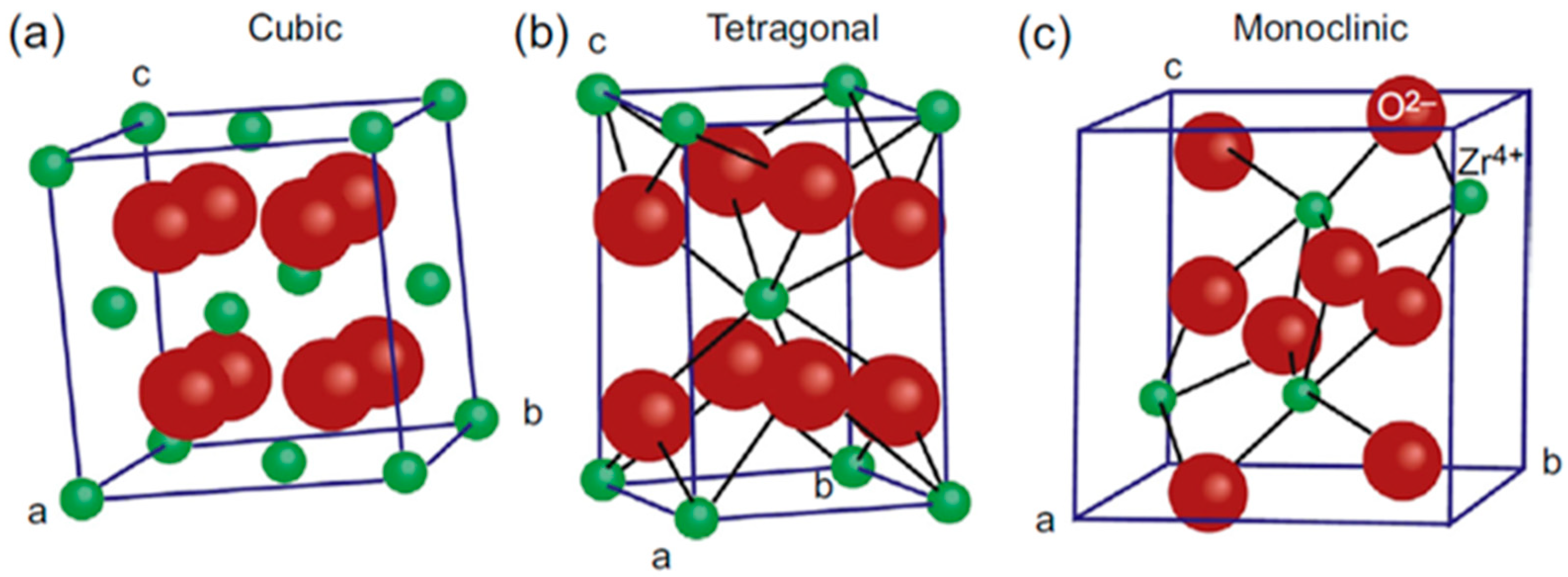
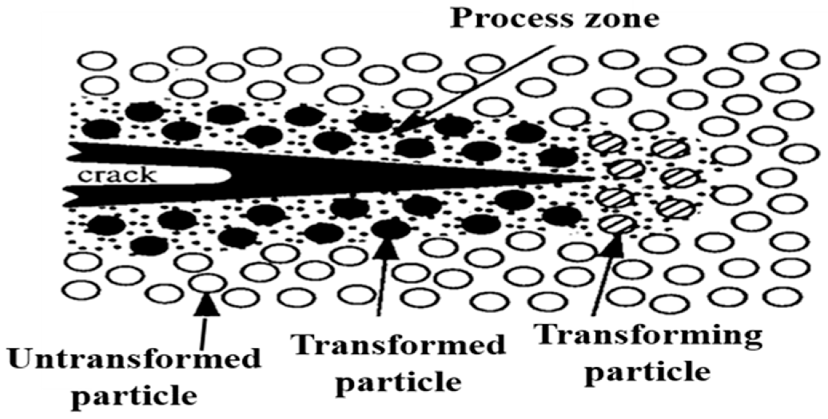
2.2. Phase Transformation

The stress-induced transformation from tetragonal to monoclinic mostly occurs in TZPs and PSZ ceramics, where the tetragonal phase is in its metastable state at room temperature. This concept, based on a change in the grain shape accompanied by a volume increase, was discovered for the first time in the mid-1970s by Garvie et al. [31] and led to the considerable fracture toughness enhancement of zirconia composites, as pointed out earlier [25]. This mechanism is known as transformation toughening in zirconia and involves a microcracked process zone at the crack tip, as shown schematically in Figure 3. As a result of crack propagation, a stress field is generated around the crack tip and contributes to the phase transformation of the surrounding particles, which occurs at a speed close to that of sound propagation in solids [21]. This phenomenon leads, in turn, to the formation of a transformed process zone constrained by the neighboring particles of the matrix.
Indeed, the surrounding untransformed particles oppose the dilated transformed zone and press back with residual stresses that cause the generation of closure forces from each side of the crack tip and hence retard crack extension. The transformation is called “stress-induced” because an externally applied stress can help the progression of transformation due to matrix stretching. According to Wolten, the phase transformation from tetragonal to monoclinic in zirconia is martensitic, i.e., its nature is similar to that of martensitic transformation in quenched steels, which is used to increase steel hardness by particular heat treatments [32].
In ceramics, martensitic transformation occurs between the parent tetragonal phase and the product through the nucleation and structural growth of monoclinic grains. This transformation is generally adiabatic and athermal, and involves atomic motion over distances smaller than interatomic spacing, resulting in microscopic changes in the shape of the transformed regions, which are associated with transformation toughening [33,34,35,36]. Furthermore, transformation toughening in PSZ is critically constrained by the particle size, which should range from 0.2 to 1 μm for 2 to 3 mol% yttria concentrations; otherwise, the transformation to the monoclinic phase can be inhibited [37,38].

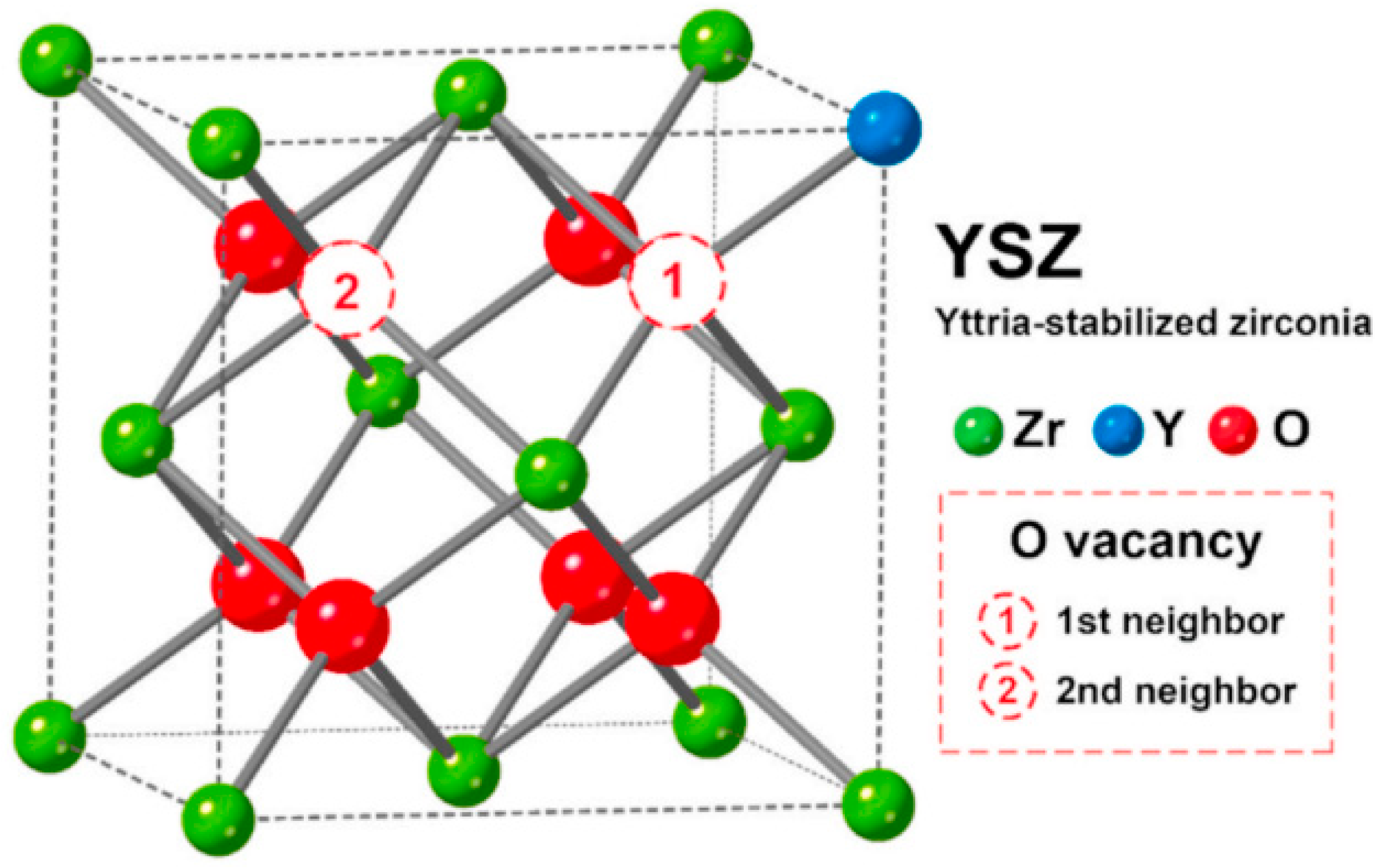
2.3. Ionic Conductivity of Yttria-Stabilized Zirconia (YSZ)

Fully stabilized zirconia (FSZ) with a cubic fluorite structure is commonly known as a solid electrolyte that possesses high oxygen ionic conductivity extended to wide ranges of temperature and oxygen partial pressure, and it is extensively employed as an oxygen sensor to control the emissions of automotive systems, combustion control for furnaces and engines, and as a solid electrolyte for high-temperature fuel cells and hydrogen production. The dopant trivalent cations require a minimum activation energy. The cubic fluorite structure of zirconia becomes stable at room temperature with high Y2O3 addition and exhibits high ionic conductivity at high temperatures [39,40,41,42]. When doping ZrO2 with Y2O3, the Y3+ cations replace Zr4+ cations, as shown in Figure 4. This induces the formation of oxygen vacancies that maintain charge neutrality in the lattice.
Two types of interactions are established by the oxygen vacancies in the lattice, i.e., repulsion with themselves and attraction toward the acceptor (Y3+ cations). As yttria has one fewer valence electron than zirconium, one oxygen vacancy is created for two substituted Y3+ cations. Consequently, the oxygen ions are free to move from vacancy to vacancy in the lattice, thereby increasing the ionic conductivity of zirconia. The corresponding reaction in Kroger–Vink notation is described as follows [39]:
Y 2 O 3 Z r O 2 2 Y Z r + V O + 3 O O X
The maximum ionic conductivity is reached when zirconia is doped with 8 to 9 mol% Y2O3. Higher doping rates will result in reduced mobility of the oxygen vacancies and the creation of complexes with positive effective charge due to the bonding between an oxygen vacancy and one cation according to the following notation [40]:
Y Z r + V O Y Z r V O
The mobility of oxygen vacancies diminishes sharply with higher yttria concentrations, as one oxygen vacancy is bonded to two cations, leading to the formation of clusters and more complex associations, as shown by the following Equation (3) [41]:
2 Y Z r + V O Y Z r V O Y Z r X

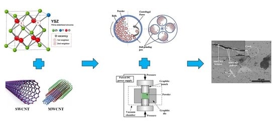
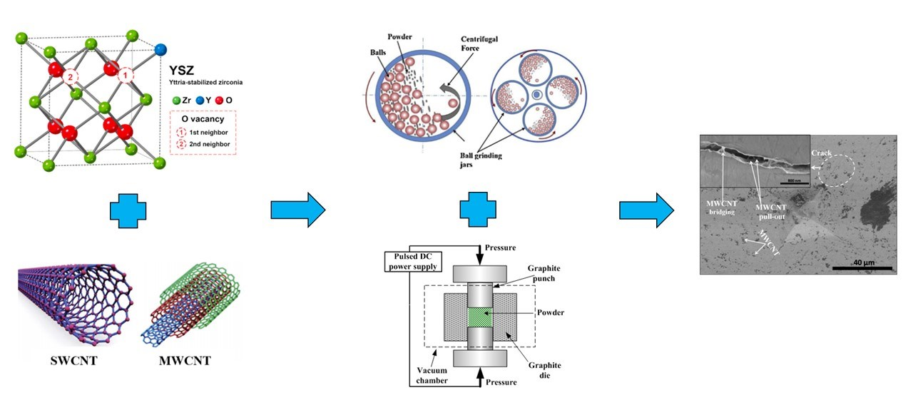
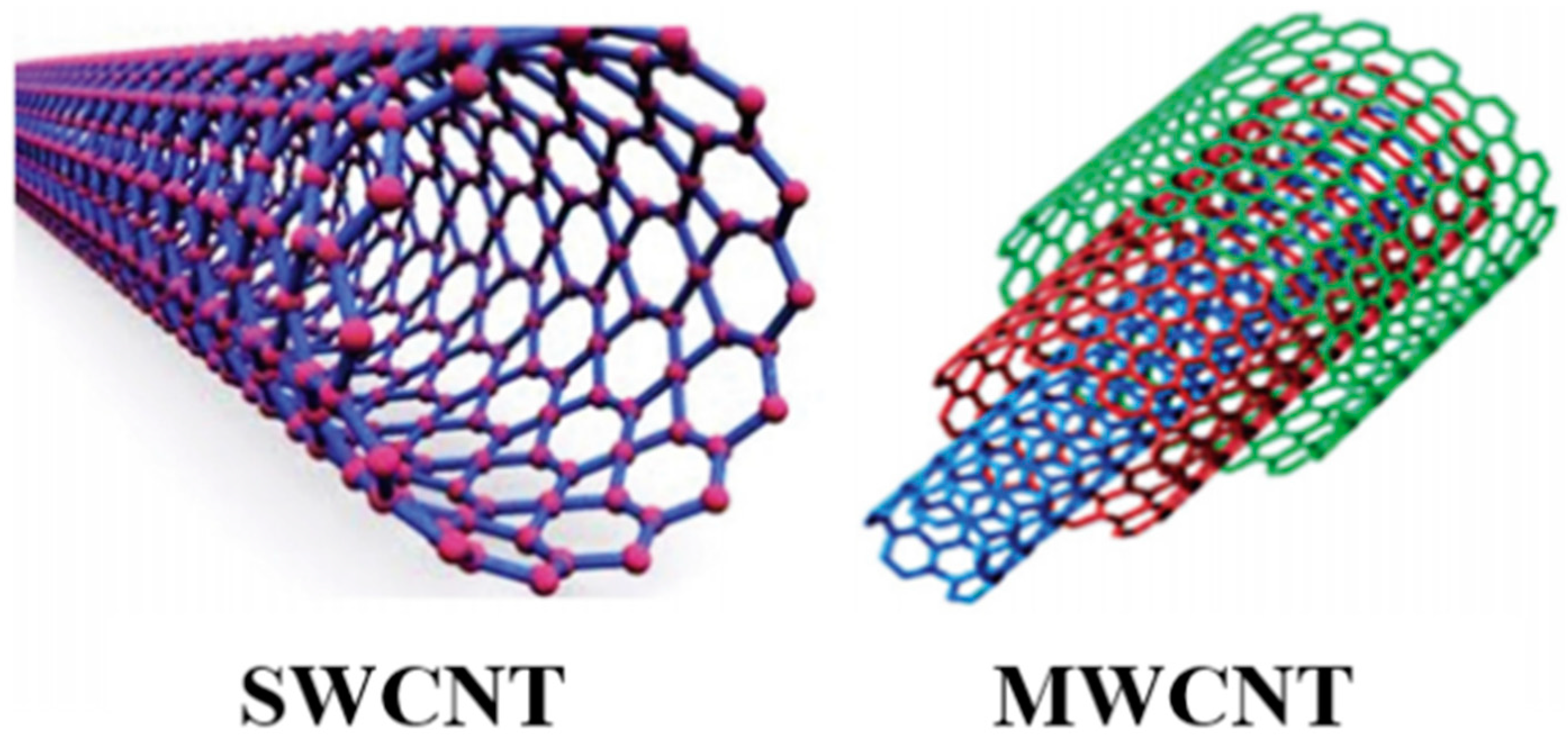
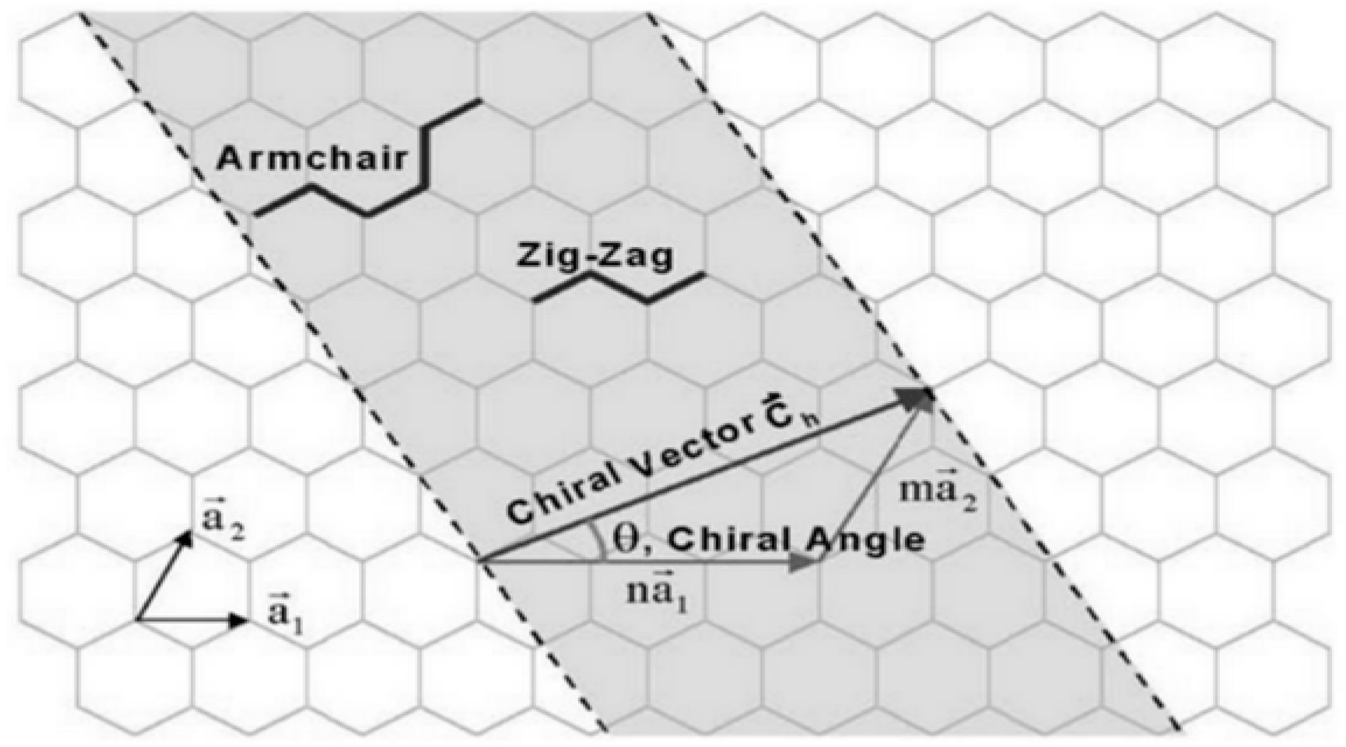
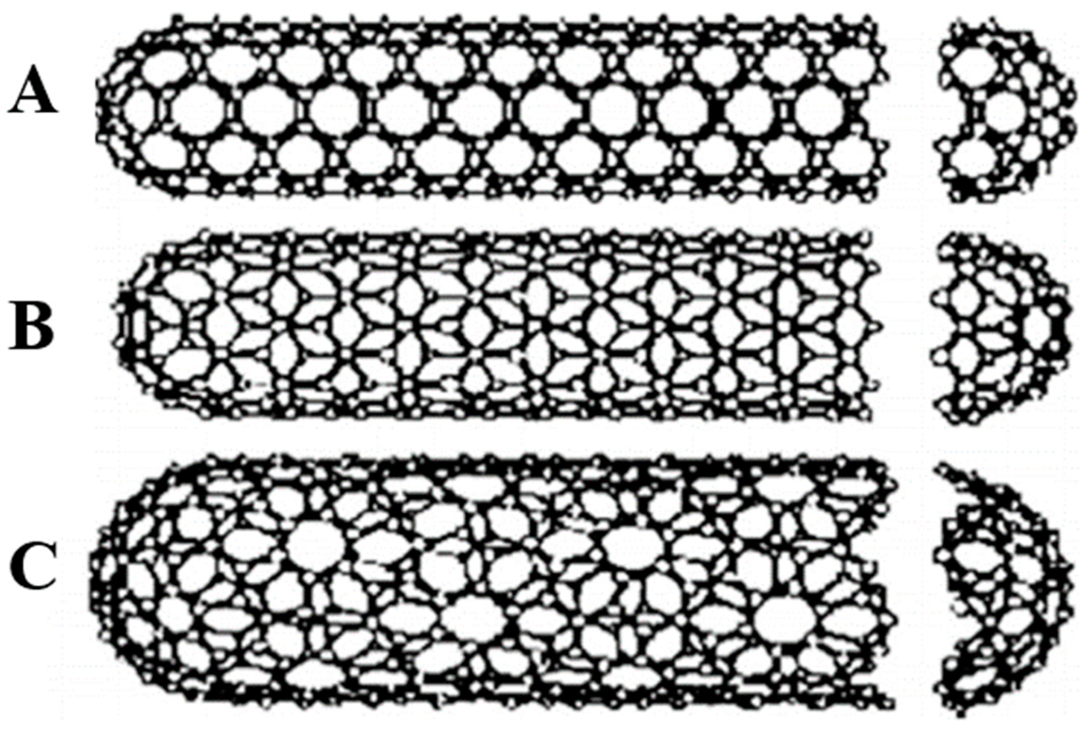
3. Carbon Nanotubes (CNTs): A Valuable Second Phase in Zirconia-Based Composites
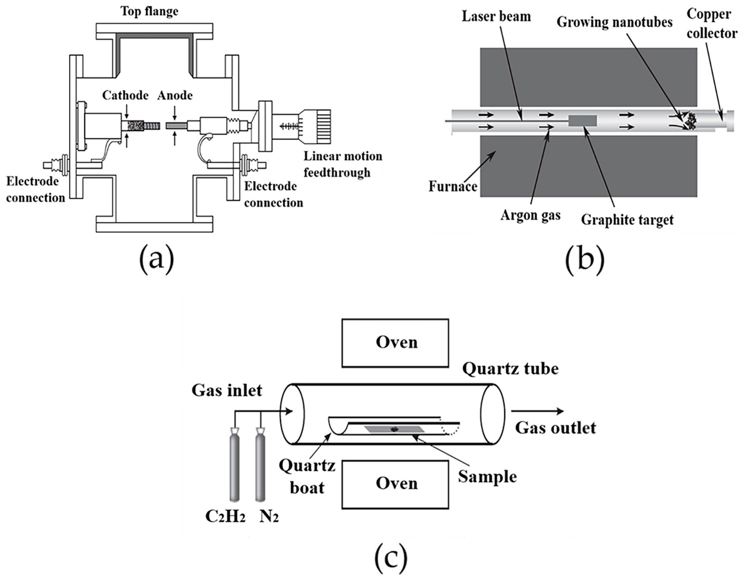
The discovery of carbon in the form of graphite was achieved in 1779, followed by diamond 10 years later. These two enormous discoveries in the field of nanotechnology generally and carbon structure specifically stimulated researchers worldwide to increase their interest in finding other forms of more stable and structurally ordered carbon. In 1985, a new form of carbon known as fullerene was accidentally discovered by Kroto, Smalley, and Curl (Nobel Prize in Chemistry in 1996) [44]. The structure of fullerenes is almost similar to that of a single sheet of graphite (graphene), with a planar honeycomb lattice, in which each atom is attached to three neighboring atoms (hexagonal rings) via a strong chemical bond. However, fullerene sheets exhibit additional pentagonal or sometimes heptagonal rings and are not planar like graphene, and can also generate three-dimensional (3D) structures similar to a football.
A few years later, in 1991, the Japanese scientist Iijima [9] discovered multi-walled carbon nanotubes (MWCNTs) with an outer diameter ranging from 3 to 30 nm and at least two layers. Later, in 1993, he discovered a new class of CNTs, single-wall carbon nanotubes (SWCNTs). SWCNTs tend to be curved, rather than straight, with a typical diameter between 1 and 2 nm. The different types of CNTs are presented in Figure 5. CNTs are cylindrical fullerenes with a nanometric diameter and micrometer-scale length, leading to a high length-to-diameter ratio exceeding 107. CNTs self-align into chains by van der Waals forces, where the carbon atoms are sp2-bonded with a length of approximately 0.144 nm. In MWCNTs, the interlayer distance between two successive CNTs is similar to the interspaces between two successive graphene layers in graphite (about 3.4 Å).
Since their discovery, MWCNTs have opened up an incredible range of promising applications in nanocomposites, nano-electronics, medicine, energy, and construction. Indeed, CNTs exhibit novel and unique properties, namely very high tensile strength (≈100 GPa) and Young’s modulus (≈1500 GPa), high thermal conductivity and chemical stability, and excellent electrical conductivity similar to those of silver and platinum [6,45,46].
Several CNT structures can be produced depending on the fullerene sheet orientation on rolling. The numerous ways to roll fullerene into cylinders are specified by the chiral vector c h determined by two integers (n, m) and chiral angle (θ) located between the chiral vector and zig-zag nanotube axis, as shown in Figure 6 and described in Equations (4) and (5):
c h = n a 1 + m a 2
θ = t a n 1 m 3 / m + 2 n
where a 1 and a 2 are the unit cell vectors of the two-dimensional lattice formed by the fullerene sheets.
As the chiral vector is perpendicular to the CNT axis, its length forms the CNT circumference and can be calculated according to Equation (6):
c h = C = a n 2 + n m + m 2
The length a is calculated based on the length of the carbon–carbon bond acc, generally approximated to 0.144 nm for fullerene sheets, as given by the following relation:
a = a 1 = a 2 = a c c 3
The diameter can be deduced from the chiral vector length C as follows:
d = C / π
CNTs can be classified either as armchair, zig-zag, or chiral tubes according to the pair of integers (n, m) in the chiral vector relation (Figure 6). In armchair and zig-zag CNTs, the structure follows mirror symmetry along both axes (longitudinal and transverse) due to the arrangement of hexagons around the circumference. On the contrary, chiral CNTs are characterized by a non-symmetric structure; therefore, mirror symmetry is not achieved. These three different structures and enrolments of fullerene sheets to form CNTs are shown in Figure 7. Furthermore, the values of the integers (n, m) influence the optical, mechanical, and electronic properties of CNTs. CNTs are considered as semiconductors when n m = 3 i ± 1 and metallic when n m = 3 i [10,48].

Synthesis of CNTs

CNTs can be synthesized through different methods, the most commonly used being arc discharge, pulsed laser deposition (PLD), and chemical vapor deposition (CVD). However, the ability to achieve a compromise between the quantity, quality, and low cost of the produced CNTs still remains an important research challenge, as the effectiveness of these methods differs from one to another. CNTs were initially detected in 1991 during an arc discharge consisting of two graphite electrodes under a current of 100 A, which was intended to produce fullerenes. This technique requires the application of a direct current (DC) arc discharge between two carbon electrodes under an inert atmosphere with or without a catalyst. As a result, the carbon particles sublimate under the high temperature between the electrodes (3000 and 4000 °C), then self-assemble at the negative electrode or on the walls of the chamber (Figure 8a). MWCNTs can be produced mainly when using pure graphite electrodes. In the case of SWCNT synthesis, the anode requires a mixture of graphite and a metal catalyst, such as Y, Mo, Fe, Co, or Ni.
Compared with the other methods, the arc discharge technique has the advantages of not being too expensive, simplicity, and being able to produce large quantities of CNTs. However, this method requires a large number of purification stages and the self-alignment of CNTs cannot be controlled, which leads to short CNTs with random sizes and directions [4,46]. The first growth of SWCNTs using the PLD method (Figure 8b) dates back to 1995 at Rice University, where a remarkable amount of pure SWCNTs about 5–20 μm in length and from 1 to 2 nm in diameter were synthesized. Similar to arc discharge, in this method, carbon atoms are vaporized from a target graphite pellet at high temperatures (about 1200 °C) under a constant flow of inert gases and a high-power laser beam, rather than electricity. This results in carbon accumulation at the walls of a quartz tube, which is cooled by water. SWCNTs can be produced from graphite pellets doped with a catalytic material, such as nickel or cobalt. Generally, this technique is considered as an excellent method to synthesize SWCNTs with high purity and controllable size. However, it is not suitable for large-scale applications due to the expensive power generation requirement (lasers) [49]. Catalytic chemical vapor deposition (CCVD) enabled the commercialization of a wide range of CNTs with comparatively reasonable cost, as it affords an easier process and the possibility to produce quite pure CNTs with controllable parameters, such as diameter/length, homogeneity, orientation, and density.
The process involves a carbon source, mainly hydrocarbons, such as acetylene, ethylene, or ethanol, and metal catalyst particles, usually cobalt, nickel, iron, or a combination of these, such as cobalt/iron or cobalt/molybdenum. The catalyst tends to decompose the carbon-containing gas in the presence of plasma irradiation or heat (600–1200 °C) and to induce the nucleation of CNTs. As a result, the free carbon atoms recombine in the form of CNTs on the substrates, some common examples of which are Ni, Si, SiO2, Cu, Cu/Ti/Si, stainless steel, or glass. Figure 8c shows the experimental set-up of the discussed methods to synthesize CNTs [46,49].

4. Processing Techniques Used to Produce CNT-Reinforced Zirconia-Based Nanocomposites
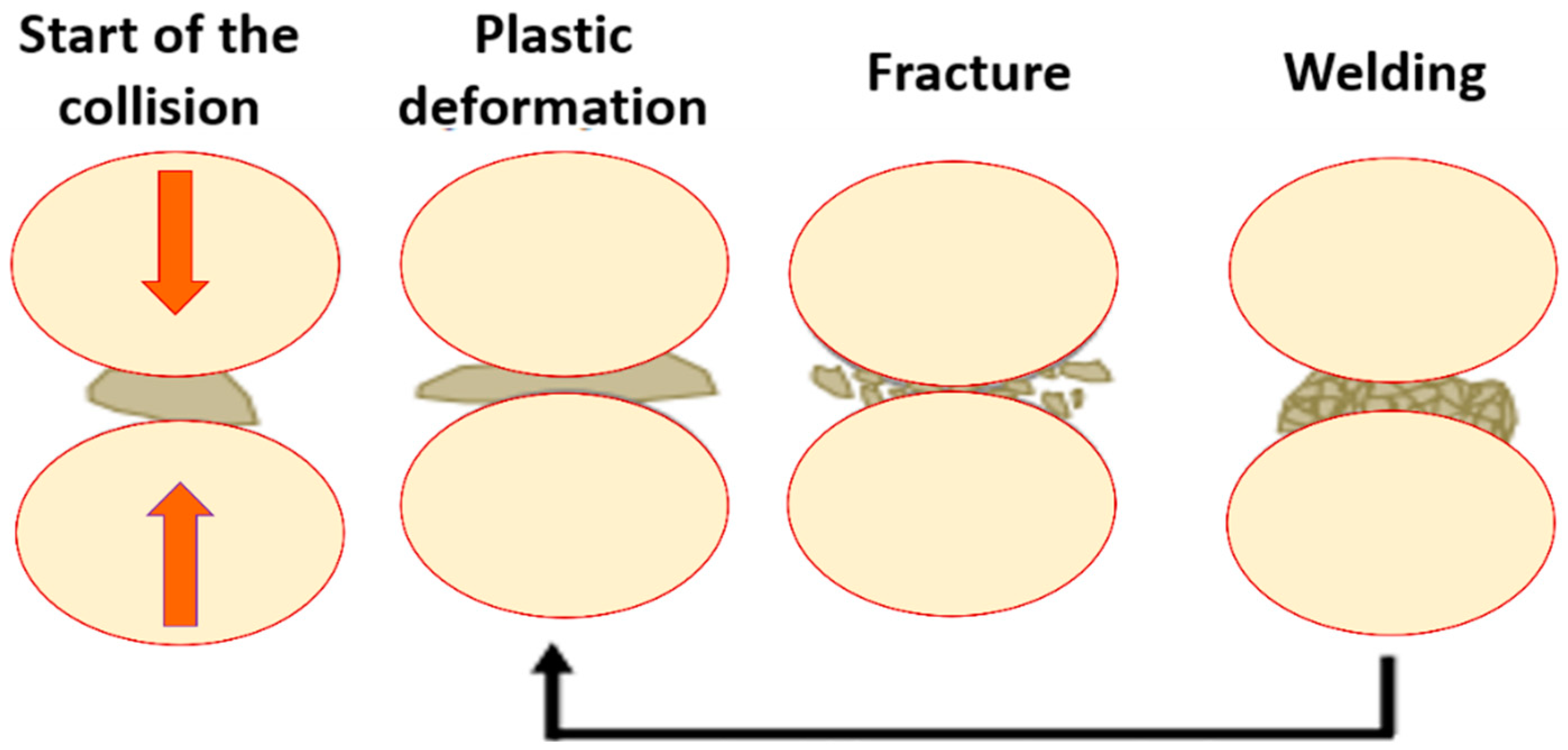
Different processing routes have been proposed over the last few years for the preparation of CNT/ceramic-matrix composites, as comprehensively reviewed by Chan et al. [50]. The techniques may greatly vary depending on the type of ceramic used, but, in general, a sintering step is always necessary to consolidate the final product. Sintering may be combined or not with a pressing stage; recently, spark plasma sintering (SPS) has attracted significant interest to reduce the risk of thermal damage to CNTs owing to the low temperature required for sintering and short sintering time.
In the case of CNT/zirconia composites, processing is typically based on ball milling and SPS; therefore, the focus is on these methods. Other strategies, which have not been specifically applied to producing CNT/zirconia composites so far, but that could be of interest for future research on this topic, are shortly mentioned in a dedicated subsection.

4.1. Ball Milling

Techniques originally developed for powder metallurgy, such as the ball milling method, are considered as a major tool to produce homogeneous and uniform dispersions of advanced ceramic powders and their composites. A subsequent stage of sintering will then allow for the consolidation of the final product. Particle agglomeration prevention and homogeneous and uniform dispersion of MWCNTs into the structural ceramic matrix represent crucial challenges during the mixing process. In fact, the powder mixture features largely influence the properties of the final composite, such as its strength, density, wear resistance, friction, etc. Ball milling synthesis for ceramic/MWCNT powder mixes is the most popular approach due to its simplicity and energy efficiency that promote high grain refinement and phase homogenization. High milling energies are essential for breaking the interlayer Van der Waal’s forces between carbon surfaces that cause agglomeration and lead to high MWCNT surface energy. The high rotational speed of the ball milling devices enables the balls to strike with the walls of the jar where high-energy collisions arise [51]. The ceramic crystalline lattice undergoes severe mechanical deformation (fractures) and stress concentration during the process (Figure 9).
As the milling time increases, powder refinement takes place, resulting in a significant reduction in the particles’ sizes until they are able to sustain deformation without any fracture. Ball milling using liquid media has been proven to show higher efficiency in inhibiting agglomeration compared with the dry process, as reported by several studies [52,53]. On the other hand, powder contamination can be an issue with ball milling; therefore, a protective atmosphere and ceramic milling jars and balls are recommended when milling hard ceramic particles. A good example of a ceramic material for milling jars and balls is tungsten carbide, which demonstrated almost no contamination of the final powder mix [49,51]. Shi and Liang investigated the effect of MWCNT addition on the electrical and dielectric properties of 3 mol% yttria-stabilized tetragonal polycrystalline zirconia ceramic (3Y-TZP) [54]. The starting materials (MWCNT and 3Y-TZP) were mixed in different weight fractions by ball milling, and the blend was further ultrasonically dispersed. After drying, the mixture was sintered at 1250 °C in a vacuum under a pressure of 60 MPa through SPS. The DC conductivity of the composites followed typical percolation behavior with a very low percolation threshold between 1.0 and 2.0 wt% MWCNT content, while the dielectric constant was greatly enhanced when the MWCNT concentration was close to the percolation threshold. In another study, Zhou et al. examined the effects of MWCNT content and heterocoagulation pre-treatment on the mechanical properties of 3 mol% yttria-stabilized zirconia (3Y–ZrO2) ceramics prepared through the ball milling, spray-drying, and hot-pressing processes [55]. The heterocoagulation pre-treatment was revealed to play a key role in the homogeneous dispersion of MWCNTs in the ceramic matrix. Moreover, the composite with 1.0 wt% of MWCNT content exhibited a flexural strength and fracture toughness 8.4 and 21.1% higher, respectively, than those of blank 3Y–ZrO2 ceramics. In a similar study, Chintapalli et al. evaluated the influence of MWCNTs on the microstructure and mechanical properties of 3Y-TZP [56]. Commercially available zirconia powder stabilized with 3 mol% yttria was mixed with 0.5, 1, and 2 vol% MWCNTs to prepare the composite materials. The nanotubes were initially dispersed in N, N dimethylformamide (DMF) using ultrasonication for 2 h. The zirconia powder was preheated at 750 °C for 1 h and then added to an ultrasonicated MWCNT–DMF solution. The batch was milled in a planetary ball mill for 4 h using zirconia balls with different sizes (10–5–3 mm), and, subsequently, the milled slurry was collected into a stainless-steel tray and dried on a hot plate at 70 °C for 24 h. Finally, the powder was sieved using a mesh of 250 μm and sintered by SPS at a maximum temperature of 1350 °C, resulting in a homogeneous distribution of MWCNTs with a small average matrix grain size in the range of 153–182 nm. Interestingly, the composite with 2 vol% MWCNTs exhibited an indentation fracture toughness and a hardness 15% higher and around 10% lower, respectively, than those of their monolithic counterparts, while the elastic modulus and the intrinsic fracture toughness practically did not change.
The risk of mechanical damage to CNTs due to the ball milling procedure was reported to be negligible. Lamnini et al. investigated the effect of attrition milling on 8 mol% yttria-stabilized zirconia (8YSZ)/MWCNTs mixtures by using high-resolution transmission electron microscopy and Raman spectroscopy, and found that the structure of the MWCNTs remained intact after milling, while the 8YSZ grain size decreased steadily [57].

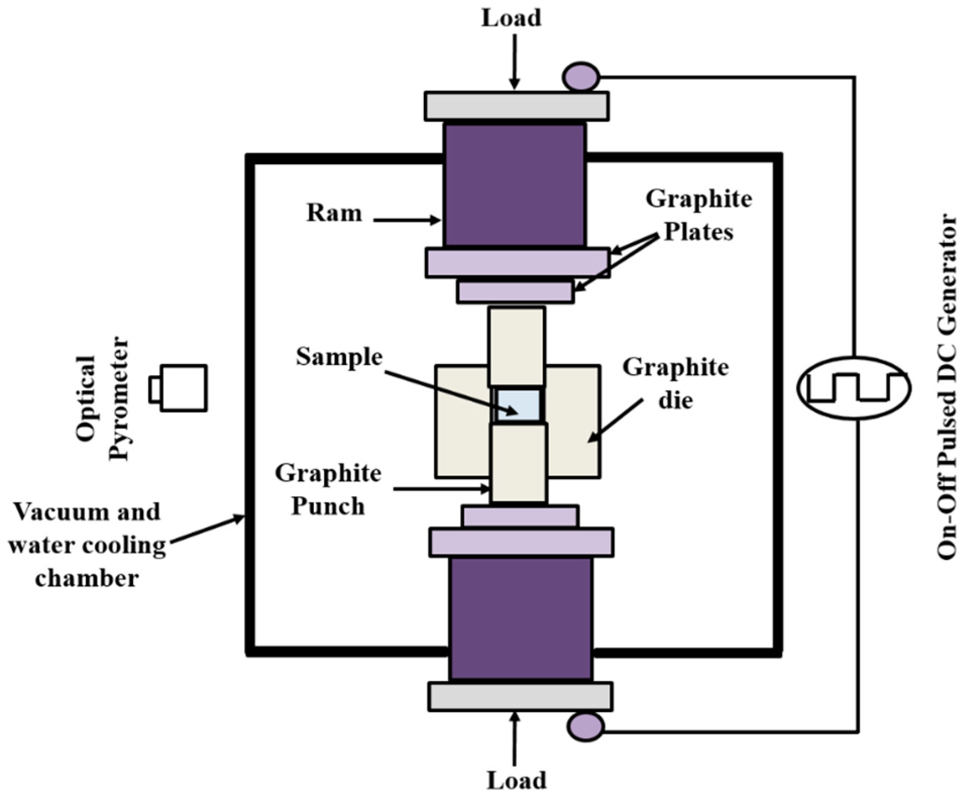
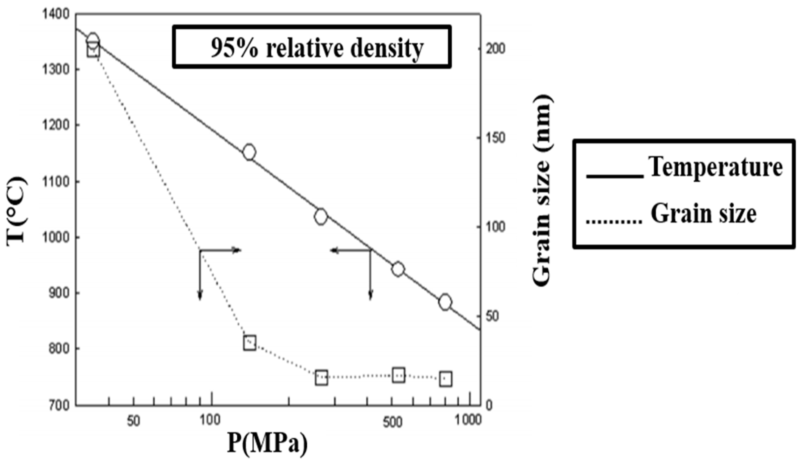
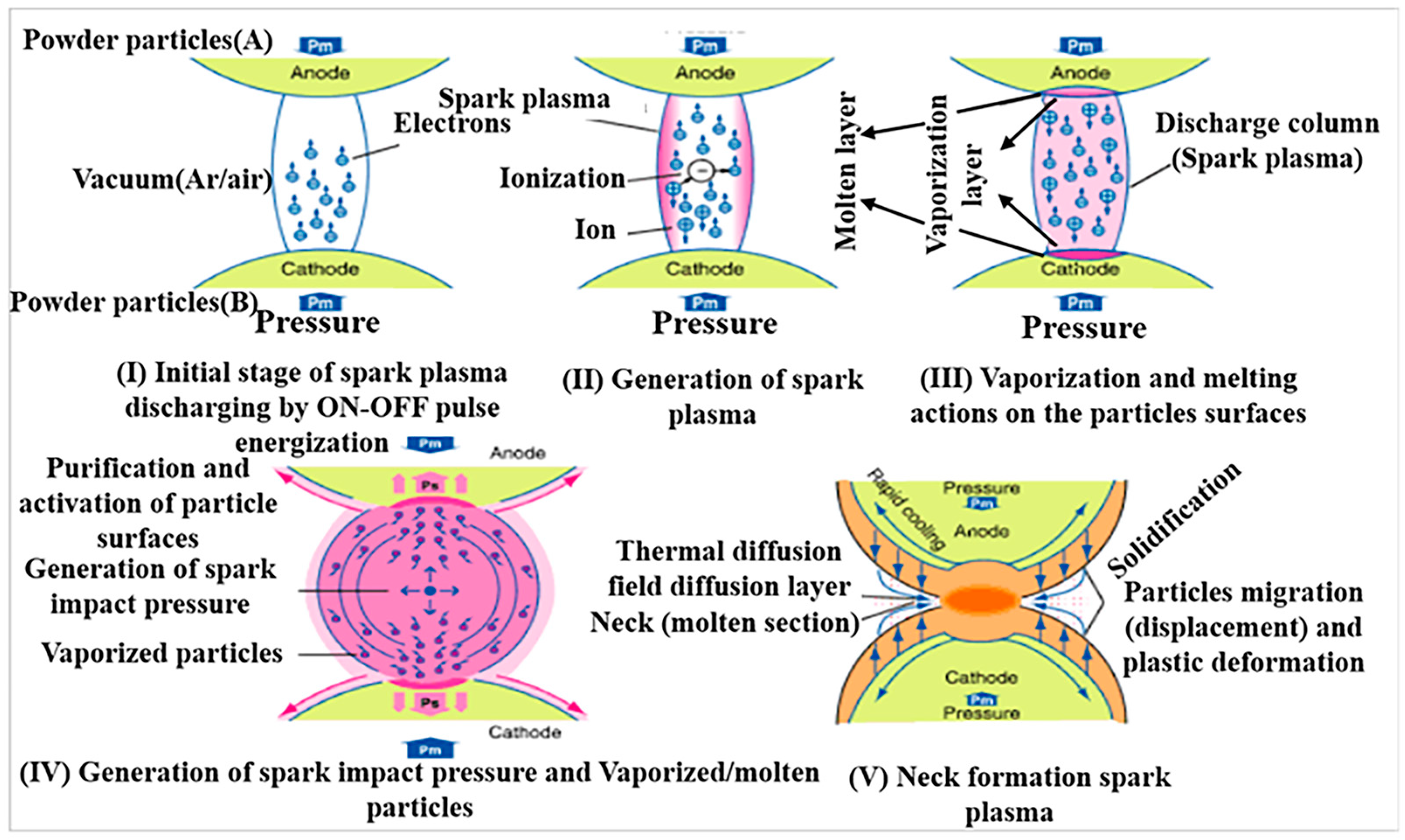
4.2. Spark Plasma Sintering

Spark plasma sintering (SPS) is a powder metallurgy process enabling the rapid synthesis of a wide range of advanced materials with small grain sizes and at relatively low temperatures. SPS uses a highly pulsating DC to directly heat specimens simultaneously with the application of uniaxial pressure to consolidate powders into a bulk material [58,59]. The first SPS machine based on a pulsed current was developed by Inoue et al. in the early 1960s [60]. Their invention was based on the idea of sintering under an electric current patented first in 1906. However, reaching high efficiency with a reasonable equipment cost was a critical point that limited its wider commercialization [61].
The advantages of the SPS process over other traditional sintering methods, such as hot pressing and hot-isostatic pressing (HIP), are the ability to consolidate high-temperature ceramics, metals, and composites in few minutes (1000 °C/min), resulting in reduced duration and energy costs [60,62], and high thermal efficiency due to the absence of any heating elements. SPS heats by passing a highly pulsed direct current through a graphite die and the sample to be sintered. A typical SPS configuration [63] is illustrated in Figure 10. The powder is inserted into a conductive graphite die in a water-cooled SPS chamber. During sintering, a uniaxial pressure is applied to the die by an upper and a lower punch. Then, a pulsated current is directed through the punch and the die for thermal heating under vacuum or protective gas evacuated and filled through the water-cooled chamber. The sintering temperature can be adjusted to a high value, namely 2400 °C, using either thermocouples or axial/radial pyrometers. The SPS process enables more uniform Joule heating conditions, especially for conducting samples. Furthermore, the current largely enhances the mass transport mechanism through electro-migration, which contributes to obtaining dense samples with finer grain structures, despite the low sintering times and temperatures [64,65,66].
Furthermore, high mechanical pressure in the range of 50–250 kN can be applied to enhance the densification by increasing the contact between grains and breaking down the agglomeration, especially for large particles [59]. In fact, a considerable improvement in particle rearrangement can be obtained by uniaxial pressing due to superplastic flow generation via grain boundary sliding. In this context, Anselmi-Tamburini et al. elucidated the effect of pressure on densified specimens based on the driving force for initial densification [64]. According to Equation (9), the driving force for densification increases proportionally with the applied pressure [67]:
D r i v i n g   F o r c e = γ + P × r π ,
where γ is the surface energy, P is the applied pressure, and r is the particle radius.
However, based on an experimental demonstration, Skandan et al. proved that a beneficial effect of pressure on densification occurs only if the pressure effect exceeds that of the surface energy [68]. In other words, the smaller the particles, the higher the pressure required to enhance densification. The effect of temperature and pressure on the grain size of zirconia samples sintered with the SPS technique is presented in Figure 11. It is shown that applying high pressure simultaneously with low temperature is efficient for producing grains with a minimal size. Hence, the optimization of pressure and temperature is a key factor in the fabrication of dense zirconia samples [69].
The appearance of spark discharges caused by the alternative switching on and off of the DC creates hot regions where the impurities located between particles are melted and vaporized. This process has been ascribed mainly to the generation of weak plasma through the powder sintered under a pulsed current and causes a phenomenon referred to as “necking”, leading to the high purification and joining of the densified particles. The detailed steps of the process are shown in Figure 12. However, the concept of plasma still remains not adequately understood without providing a direct justification for its existence. Thus, plasma generation represents an important objective of the struggle to establish an implicit understanding of the process.
Robles Arellano et al. investigated the effect of the sintering technique on the densification behavior of 8 mol% yttria-stabilized zirconia (YSZ)-based composites with the addition of 11.6, 21.6, and 30.5 wt% La2O3 [70]. Their work clearly demonstrated the advantage of SPS in attaining a high densification level (∼92–96%) in La2O3 + YSZ composites with significantly lower time, pressure, and temperature process conditions (1500 °C, 50 MPa, and 10 min, respectively) compared with pressure-less sintering with a lower relative density of about 82% at 1600 °C held for 2 h and the HIP sintering technique with a relative density of 99.7% performed at 1500 °C and 196 MPa for 2 h.
In addition, Mazaheri et al. investigated the processing features of YSZ reinforced with MWCNTs and sintered by SPS [71]. It was found that SPS was an efficient way to produce fully dense composites with the ability to reduce CNT structural damage at high temperatures, contrary to the conventional sintering methods. It also enabled strong bonding between MWCNTs and the ceramic matrix, which was a prerequisite for enhanced mechanical properties. In a similar study, Karanam et al. investigated the densification behavior in 0.2, 0.5, and 1 wt% CNT-containing YSZ-matrix ceramic composites processed via SPS [72]. In their work, the detailed interpretation of the advantageous role of the SPS process and CNTs in enhancing the hardness and resistance to crack propagation in YSZ/CNT ceramic composites was reported. Indeed, it was found that the presence of CNTs within the YSZ matrix led to delayed densification and grain growth during the SPS process, which, in turn, reduced the density of the composite. However, during the SPS process, the CNTs helped to pin grain boundaries, which resulted in enhanced mechanical properties.

4.3. Other Possible Manufacturing Approaches

Several other methods addressed to produce CNT/ceramic (other than zirconia) composites have been reported in the literature. Although not being specifically applied to the case of CNT/zirconia composites so far, they deserve further investigation for possible extension to this field. In this regard, various dispersion methods have been experimented with by several groups pursuing the homogeneous distribution of CNTs at the ceramic grain boundaries and eventually enhancing the CNT-CMC properties. For example, colloidal processing [73] and the sol–gel method [74] are used in applications of surface functionalization on CNTs to achieve a homogenous dispersion in ceramic matrices. Colloidal processing techniques include CNT dispersion methods with water or organic solvent (e.g., DMF and acetone) using sonication or magnetic stirring to produce CNT nanofluids. On the other hand, the synthesis of CNT–ceramic composites by sol–gel processing techniques typically is a multistep, time-consuming procedure that involves the preparation of appropriate solutions (e.g., ceramic precursors, gelling catalysts, pH-controlling agents, etc.) to be added into the CNT sol, followed by aging and gelation. Then, the CNT–ceramic gel is dried and thermally treated at high temperature (calcination) in air or an inert atmosphere to finally obtain CNT–ceramic composite powders that can be used for further processing [50].

5. Mechanical Testing Methods and Properties of CNT/Zirconia and Ceramic-Matrix Composites

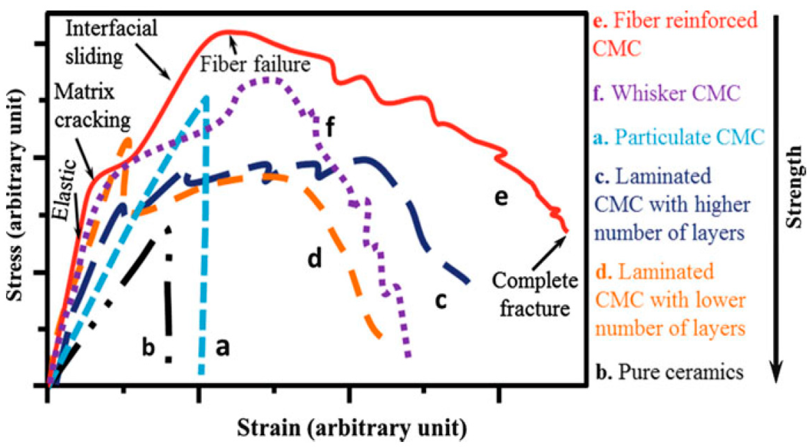
5.1. Comparative Stress–Strain Curves between Pure Ceramics and CMCs

The strength of engineering materials is commonly measured using tensile tests, where external forces tend to elongate specimens. Typical stress–strain curves comparing the tensile behavior of pure ceramics with different types of reinforced CMCs are depicted in Figure 13. In pure ceramics (illustrated by the black dotted curve), brittle fractures generally arise before the occurrence of plastic deformation. In fact, in pure ceramic materials, the binding orbitals of electrons are localized around the corresponding ion cores, restricting the movement of electrons. As a result, very high energy is required to generate the movement of dislocations and, therefore, make plastic deformation possible [72,75]. Single-phase ceramics also exhibit poor toughness compared with ductile materials, like metals.
Contrary to pure ceramics, CMCs reinforced with a second phase, such as CNTs, boron nitride nanotubes (BNNTs), or whiskers of titanium carbide (TiC), silicon carbide (SiC), silicon nitride (Si3N4), or boron carbide (B4C), led to a significant enhancement in the fracture toughness, wear resistance, and overall strength behavior [76]. Indeed, at lower applied stress, as shown in Figure 13, both pure ceramics and CMCs share similar elastic mechanical responses, which means that the material regains its initial state when the stresses are removed. This region is characterized by the elastic (or Young’s) modulus, which is commonly designated as E and can be determined mechanically from the linear region where the stress and strain exhibit a proportional relationship.
E, being an elastic constant, is calculated as the ratio of stress to strain in the initial linear region of the curve according to Hooke’s law [77]:
σ = E · ε ,
where σ is the measured stress (Pa) and ε is the strain (unitless) [78,79,80].
In addition, E can also be determined using the sonic technique. This method involves a piezoelectric transducer that measures the time of flight of transverse and shear waves. As a result, the recorded voltage as a function of time can be plotted. Owing to the minimal sensitivity to internal defects, the sonic technique is mainly employed to distinguish between the different materials in composite or joined systems [80,81].
When the applied stress increases above the yield strength of the matrix, matrix cracking starts to take place. As a result, the stress–strain curve of CMCs follows a nonlinear behavior, as can be seen in Figure 13. At even higher stress, the cracks reach saturation, and the curve remains nearly constant. The maximum of the curve is reached when the second phase (especially fibers) starts to crack, and the final step is characterized by material failure.
It should be underlined that the fibers and whiskers form an additional resistance barrier when stress is applied, resulting in pull-out, crack bridging, and crack deflection [82]. As a consequence, this mechanism leads to crack self-healing and strong bonding within the ceramic matrix. Thus, higher tensile strength is achieved in CMCs compared with pure ceramics.
Generally, the tensile strength of ceramic composites is much lower than their compressive strength (about ten times). This is due to the external forces applied during the compressive test that tend to decrease the specimen volume, thus limiting flaw propagation. Indeed, in compressive loading, plastic deformation, such as glide bands, and the pile-up of dislocations at grain boundaries occur; moreover, micro-cracks take place at very high loading, leading to the fracture of the specimen [75,83]. Consequently, ceramics are traditionally used in applications where loads are compressive; the advent of CMCs allowed for tackling the challenge—at least partially—of withstanding high tensile loads as well.

5.2. Fracture Toughness

The use of pure ceramics and ceramic-based composites in any successful application requires a careful investigation of the crack initiation and propagation mechanisms. The spontaneous extension of cracks can be described by the Griffith/Irwin criterion (Equation (11)) and refers to the stress intensity factor (SIF) (K, MPa·m0.5), which is related to the material’s ability to increase the loading in the presence of intrinsic flaws [79,84]:
K = σ Y π a ,
where σ (MPa) is the stress in the uncracked body, Y is a dimensionless geometric factor that takes into account the geometry of the specimen and the characteristics of the preexisting flaws, and a (m) is the crack length.
Failure occurs if the SIF reaches or exceeds the fracture toughness KIc, which is the resistance of the material against crack extension:
K K I C ,
The determination of fracture toughness based on conventional methods, such as single-edge notched beam (SENB), single-edge V-notched beam (SEVNB), Chevron notched beam (CNB), surface crack in flexure (SCF), and single-edge pre-cracked beam (SEPB), is hard to reliably perform on brittle ceramics or composites because of their notable brittleness and the obvious difficulty to create a sharp, pre-cracked specimen. In addition, these methods require arduous sample preparation and a particular notch geometry control to obtain only one result for each sample. Therefore, significant time consumption and expensive procedures are crucial issues in these experimental approaches [85,86,87,88].

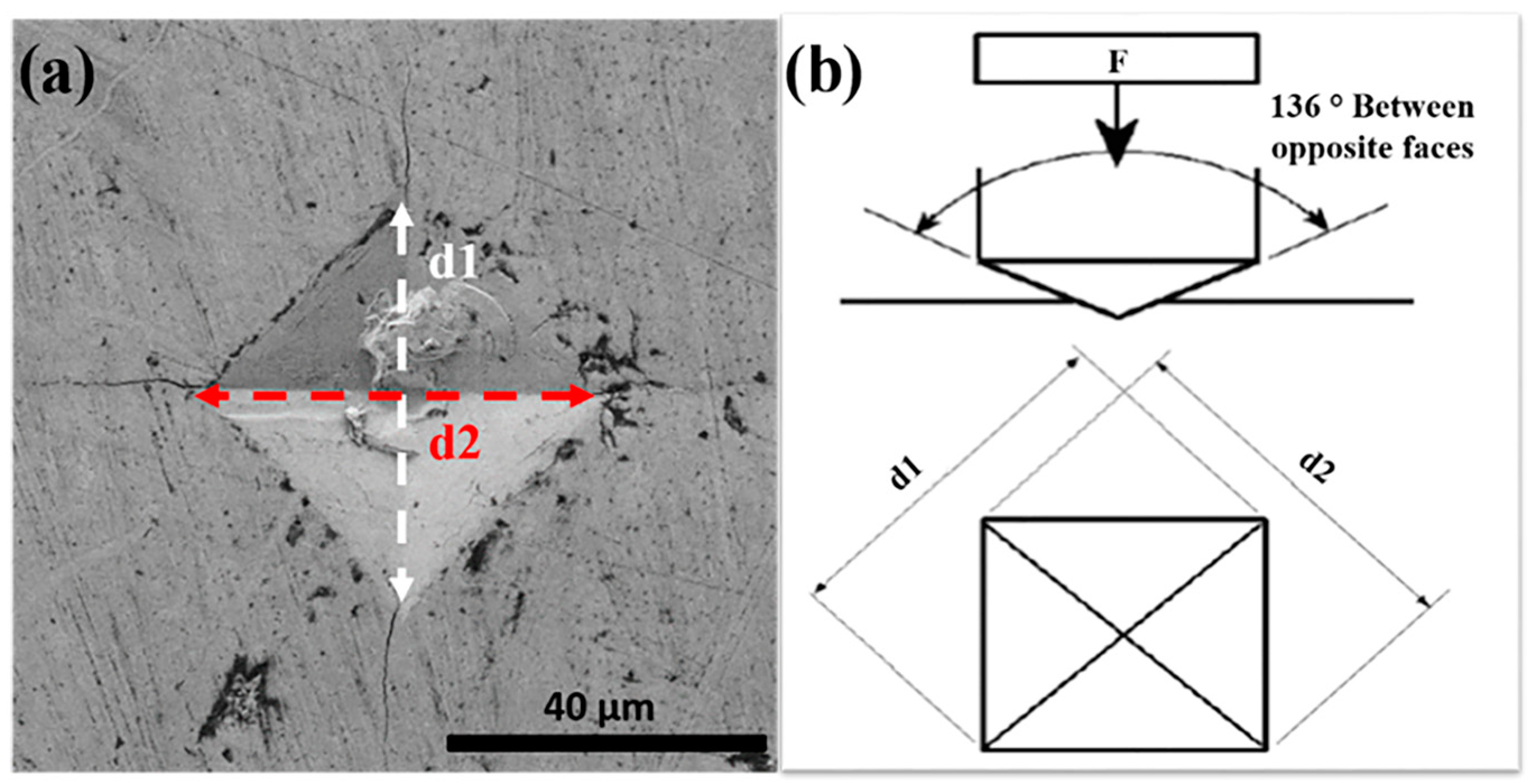
5.3. Hardness Testing

The hardness of materials is considered as a key parameter in the field of materials science, engineering design, and analysis of structures. As a general definition, hardness refers to a material quality, rather than a physical property, and it is defined as the resistance to local/surface plastic deformation or penetration by indentation, wear, abrasion, or scratching. In 1900, the Swedish engineer Brinell was the first to invent an effective and modern method using a hard steel ball as the indenter to measure the hardness of a given material. His method, named Brinell hardness testing, presented a more reliable alternative to the traditional hardness test, which measured the scratch resistance according to Mohs’ scale. Furthermore, as the tensile strength of materials can be estimated from hardness data, this test is a valuable alternative to destructive and time-consuming tensile testing, which is difficult to be performed on small-sized materials. Therefore, Brinell hardness testing using a hard steel ball as the indenter is often the only solution used to assess the mechanical properties of advanced materials [75,78,89,90].
Meanwhile, several authors dealt with hardness testing on ceramics through the discussion of indentation fracture or as a fundamental description. Among them, the most influencing ones were McColm (1990), Lawn (1993), Tabor (1951), and Chandler (1999) [91]. Today, several hardness testing variants exist, where the most common are Rockwell and Brinell tests, which are usually performed to evaluate the hardness of soft to medium-hard metals and materials with non-uniform microstructures. On the other hand, other hardness testing methods, such as Vickers and Knoop, are usually applied to ceramics [78,92]. According to the loads applied and the size of the indenter, hardness testing can be divided into two groups: macro-hardness and micro-hardness. When the applied load exceeds 9.8 N (corresponding to the mass of 1 kg), the test is known as macro-hardness and is usually performed on large-sized materials, such as testing tools, dies, etc. Below applied loads of 9.8 N, the test is considered as micro-hardness, mainly devoted to small-scale materials that include thin films, small parts, and the individual constituents of materials [83,92]. The geometry of the indenter, load, dwell time, and the means of result interpretation are the key factors differing between the mentioned hardness testing methods.
The Vickers hardness test is usually preferred for testing ceramics due to several advantages. Indeed, in addition to its extremely high precision, the Vickers hardness test uses only one type of indenter that is adaptable to all types of materials, including the “softest” and “hardest” ones (Figure 14). However, the Vickers machine is more expensive than the equipment for the Brinell or Rockwell tests [79,93]. Generally, in ceramics, hardness is closely related to yield strength σy and can reflect a material’s resistance to wear. The most cited empirical equation in the literature [84,94] that describes the Vickers hardness/yield strength relationship follows approximately the form presented below:
H V 3 · σ y
The determination of hardness has been reported to be challenging in CNT-containing ceramics. The mechanical properties—including hardness—of CNT-containing ceramic-matrix composites are sensitive to CNT agglomeration. In turn, the presence of agglomerated CNTs, which typically increases with increasing CNT concentration, was found to play a key role in decreasing hardness [95]; the same trend was also observed for fracture toughness (see Section 5.4). Although this behavior was mainly observed in CNT-reinforced alumina [96,97], similar considerations could also be extended to CNT/zirconia composites. Furthermore, the hardness test conditions also deserve to be taken into account for achieving a reliable assessment and comparison of results. In this regard, Morales-Rodríguez et al. [98] reported that performing Vickers hardness tests on the cross-sectional surfaces of SPS-consolidated CNT/alumina composites, instead of end surfaces (top/bottom), yielded a significant improvement in the reliability of measurements, which was due to the different morphologies of CNT agglomerates associated with CNT orientations. Interestingly, however, no anisotropic effect was apparently observed on the values of Vickers hardness.
Figure 14. (a) Vickers indentation under 19.6 N load in SPS zirconia matrix. Adapted with permission from Ref. [99], Copyright 2019 Elsevier. (b) Schematic of Vickers hardness principle [88].
Ceramics 06 00105 g014

5.4. Estimation of Fracture Toughness in CMCs through Indentation Tests

To overcome the experimental difficulties mentioned earlier, simpler techniques based on hardness testing have been established to estimate the toughness of ceramics. In this regard, the determination of the so-called indentation fracture toughness involves the measurement of the emanated crack lengths from the corners of Vickers or Knoop indentation diagonals. This method basically enables an easy, fast, and cheap experimental procedure in addition to the non-destructive test, as only a small sample size is required. Vickers and Knoop indentation hardness tests are the most commonly used techniques to create an indentation mark on a well- and smoothly polished sample surface. In these methods, the indenter is forced onto the surface with a high testing load until a plastically deformed region is formed below and around the indentation, resulting in cracks emanating from the four corners of the imprinted zone and residual stresses according to the material features. The indentation fracture toughness method requires the knowledge/assessment of the crack length and shape, load, imprint size, hardness, calibration constant, and, sometimes, the elastic modulus [93,100,101,102].
A large number of studies have discussed the types and roles of different crack shapes formed on a sample’s surface perpendicularly to the sharp Vickers or Knoop indenters. The most commonly known are Palmqvist and median (or half-penny) cracks [90,103,104]. Numerous studies performed on polycrystalline ceramics describe Palmqvist cracks as the four independent radial cracks that do not connect to each other under the indentation. This type of crack is mostly formed at low and intermediate loads. Above a characteristic threshold load, generally quite high, the crack merges to a median type, where the cracks are interconnected in the sample depth [91,105,106]. The two models representing Palmqvist and median cracks under Vickers indentation are illustrated in Figure 15.
Indeed, the geometry of a crack can be affected by the crack growth mechanism, which is associated with the presence of a complex residual stress network around the indentation in some materials. Therefore, in some cases, it can be hard to assess if the median crack shape is an extension of Palmqvist cracks due to residual stress or is formed directly at the beginning from the indenter [48]. The two crack shapes can be identified by several methods. A formal commonly used criterion relies on measuring the crack length/indent diagonal ratio. Indeed, when the ratio is larger than 2, the crack geometry is attributed to the median shape; otherwise, it is a Palmqvist type.
Other experimental techniques known as the decoration process [102,105,106,107,108,109] and serial sectioning technique [91,110,111,112] are widely used. The decoration of the indentation crack method proposed by Jones et al. involves a saturated lead acetate solution where the sample surface is soaked prior to the flexural test and polishing [113]. In this method, the crack path can be observed from scanning electron microscope (SEM) micrographs after the fractographic test (taking into consideration the original indentation crack as the failure origin) and the complete drying of the excess lead acetate solution, usually by using an oven.
In addition, the serial sectioning method to visualize the crack shape is based on layer-by-layer material removal by ceramographic polishing. At the end of surface polishing, the cracks remain connected to the inverted pyramid of the indentation in case of a median shape, while Palmqvist cracks exhibit a detached radial crack, as displayed in Figure 15.
By far, most of the studies cited in the literature have used Vickers indenters to determine the fracture toughness directly from the indentation mark. Different models (more than 30 equations) have been developed by a large number of authors, either by empirical or experimental processes, some of which involve the Young’s and Poisson’s modulus, in addition to the hardness test results [48,92,111,114,115,116]. Most of the equations are a reformulation of the previous equations with novel calibration constants depending on the crack type (Palmqvist or radial–median), crack length, and material properties.
As mentioned earlier, conventional techniques are hardly applicable to large-scale samples due to the laborious crack measuring, robust equipment, and the requirement for very precise notch geometry control [114]. Furthermore, the raised residual stresses and hard surface preparation can largely influence the final results.
As a consequence, in the 1970s, Evans and Charles pioneered the Vickers indentation fracture technique to assess the fracture toughness of ceramics and their composites. In 1976, they published a short communication in which they presented a normalized calibration curve fitting to correlate the crack length (c) and indentation size (a) in order to estimate the indentation fracture toughness. In their paper, a generated equation was provided that seems to be used, regardless of the crack shape (Palmqvist or median), as illustrated below [48,114]:
K I C = 0.16 c / a 1.5 H V · a 1 2
Afterward, the indentation method received much interest because of its apparent ease of application. However, the scientific community claimed that it was important to establish new indentation-based models for each crack type to obtain more accurate fracture toughness values.
Consequently, in 1982, Marshall et al. [116] revised the formula of indentation applied to median cracks given by Evans and Charles, while Anstis et al. proposed additional modifications to the proposed equation, as presented below [115]:
Marshall and Evans [111,116]:
K I C = 0.036 E 0.4 P 0.6 a 0.7 c / a 1.5
Antis, Chantikul, Lawn, and Marshall [117,118]:
K I C = 0.016 E H V 0.5 P c 1.5
Other reformulations of the previous equations for median cracks were established by Lauginer, Casselas, and Nihara, as cited below:
Lauginer [93,118]:
K I C = 0.010 E H V 0.6 P c 1.5
Casselas [93,118]:
K I C = 0.024 E H V 0.5 P c 1.5
Nihara, Morena, and Hasselman [93,118]:
K I C = 0.0309 E H V 0.4 P c 1.5
The models assume that the residual stress formed underneath the indentation in the plastically damaged zone proceeds as an expanding cavity that pulls the median cracks apart. Subsequently, different authors described the Palmqvist cracks models to estimate the indentation fracture toughness. All the equations applied to the Palmqvist crack type use the Exner crack resistance (W) [87], defined as the ratio between the indentation load (P) and the sum of the length of the cracks at the corners of the Vickers hardness imprint using the following equation:
W = P i = 1 4 l i
The most commonly cited equations to describe the Palmqvist crack type are presented as follows:
Warren and Matzke model [117,118]:
K I c = 0.087 · H V · W 1 2
Nihara, Morrena, and Hasselman model [93,118]:
K I c = 0.0246 · E / H V 2 / 5 · H V · W 1 2
Shetty, Wright, Mincer, and Clauer model [93,118]:
K I c = 0.0889 · H V · W 1 2
However, the different proposed equations result in a large standard deviation of KIC results. In addition, when the properties are not homogeneously distributed along the sample’s surface, this method may not accurately represent the indentation fracture toughness due to the small indented zone. Therefore, several tests must be carried out on the same specimen for achieving better precision.
Eventually, some authors reported extremely high indentation toughness values (15–20%) for Al2O3/SWNT composites compared with the single-edge V-notch beam method, while other authors found no increase in the same materials [119,120]. Since then, many authors have rejected the use of indentation tests for the characterization of the fracture toughness of composites with CNTs, reporting that indentation is a questionable method for measuring fracture toughness in these materials due to the absence of radial cracks or the difficult detection of extremely small ones [121]. Thus, the use of indentation methods seems to be advisable only for the purpose of relative toughness measurement [122,123].

5.5. Bending Strength Testing

The three-point bending test is a classical mechanical testing method commonly used due to its simplicity to determine the bending strength, stress–strain behavior, and the elasticity modulus of brittle materials, such as ceramics. The geometry of the tested sample and strain rate are essential for easy analysis of the results.
Therefore, the sample should be either a cylindrical rod or a rectangular bar, as the sample geometry has to be taken into account in the final calculation. Additionally, the sample should be as flat as possible to ensure that its rotation is avoided when the loading pin contacts the sample. In a three-point bending test, a bar-shaped sample is placed on two cylindrical rods (lower supports), while the third rod is placed on the middle of the upper surface of the sample and causes a concentrated load at the mid-point and reduced stress elsewhere. This strength testing configuration creates compression stress on the concave side, tensile stress on the convex side of the sample, and shear forces along the middle plane. Hence, to prevent the contribution of shear stresses to the primary failure of the material over compressive or tensile stresses, the control of the ratio between the span and depth (height of the sample) is necessary to reduce shear stresses. On the other hand, the strength testing configuration in the four-point bending test exposes the upper surface of the material to two applied load cylinders, compared with three-point bending, which tends to produce more flaws. Therefore, the strength measured with the three-point bending test is generally higher than that measured with the four-point bending test [112,124,125]. The theoretical models of the three-point and four-point bending tests are given in Figure 16.
For the three-point bending test, the flexural strength σB3 (maximum stress at break) is calculated as follows:
σ B 3 = 3 F L 2 b h 2 M P a
For the four-point bending test, instead, the strength σB4 can be calculated as follows:
σ B 4 = 4 F L 2 b h 2 M P a
where F is the load at the fracture point (N), L is the length of the support span (mm), b is the width (mm), and h is the thickness (mm) of the specimen.
The Young’s or elastic modulus, most commonly designated as E, can be determined mechanically from the linear region, where the stress and strain exhibit a proportional relationship, as mentioned previously. In that region, the elastic modulus constant in three-point bending can be calculated according to Hooke’s law [77] reported in Equation (10).In the three-point bending test, the elastic modulus constant can be expressed as follows:
E = σ B 3 ε = F L 3 4 b h 3 δ
where δ is the deflection corresponding to the load.

5.6. Mechanical Properties of CNT-Reinforced Zirconia-Matrix Composites

As previously mentioned, the incorporation of carbon nanomaterials into brittle ceramic matrices enhances their toughness by absorbing energy during fracture. However, despite the major advantages and unique properties exhibited by CMC materials, the recent literature has reported several dissimilarities in the effectiveness of the nanomaterials dispersed within the ceramic matrix or at the grain boundaries. Indeed, this has been suggested to be linked to several issues due to the choice of synthesis techniques or sintering treatment. Zahedi et al. [117] studied the effect of wet and dry media on dispersing different volume fractions (1.3, 2.6, and 7.6 vol%) of CNTs within an 8YSZ matrix. Wet media have been revealed to be more effective than dry media to disperse CNTs and reduce their agglomeration, thus allowing denser composites to be obtained. Furthermore, a significantly high improvement in the toughness toward saturation has been found with a relatively high CNT volume faction (7.6 vol%), while the hardness was found to slightly decrease. Melk et al. [118] claimed similar behavior with 3 mol% yttria-stabilized tetragonal zirconia polycrystals (3Y-TZP) doped with a MWCNT content from 0.5 to 4 wt%. In fact, the hardness decreased proportionally with the MWCNT content, while 2 wt% MWCNTs allowed the strongest fracture toughness to be achieved (4.97 ± 0.06 MPa·m0.5). In a similar study, Lamnini et. al. [99] reported high degradation of mechanical properties at 5 and 10 wt% MWCNT contents within an 8YSZ matrix. Furthermore, the distribution of toughness throughout the composites’ surface showed a slight increase at some positions with 1 wt% MWCNT addition. SEM micrographs have revealed the presence of several toughening mechanisms, such as MWCNT pull-out, crack bridging, and crack deflections and branching, as illustrated in Figure 17. These toughening mechanisms induced by the nanotubes were present to restore the original toughness of the matrix. Interestingly, however, the slight increase in the fracture toughness (about 9%) associated with adding 1 wt% CNTs to a zirconia matrix as compared with pure zirconia was inconsistent with the improvement of 36.7% reported in another study when the same CNT amount was added to alumina [126].
In another study [127], zirconia-toughened alumina (ZTA) composites containing 0.01 and 0.1 wt% MWCNTs and densified by SPS at 1520 °C were prepared and mechanically investigated. The Vickers hardness at a 980 N (10 kg) load of ZTA-CNT ceramics decreased slightly with 0.01 wt% MWCNTs, then increased substantially with 0.1 wt% MWCNTs to reach 19.39 ± 0.15 GPa, further exceeding that of a composite free of MWCNTs. Meanwhile, the fracture toughness showed no improvement, and even decreased upon the addition of MWCNTs.
Table 1 summarizes the mechanical properties and density measurements of SPS-densified zirconia matrix-based monolithic ceramics and ceramic composites reinforced with CNTs reported in the literature. The mechanical properties, evaluated by indentation-based measurements, clearly reveal an increase in the fracture toughness of the ceramic materials upon the incorporation of the carbon filler, except for the case of ZTA composites, as anticipated above [127].
The reason why such controversial results have been experimentally found by scientists may be due to the fact that the actual mechanism behind the CNT-related reinforcement has not been clearly elucidated yet for both high and small amounts of CNTs added to zirconia and, in general, ceramic matrices. For example, on one hand, Lamnini et al. proposed CNT pull-out as the key for the toughening mechanism based on SEM evidence [89], and on the other hand, Song et al. reported the lack of CNT pull-out from the composite and CNT bridging, which led to no improvement in hardness and even yielded reductions in toughness and bending strength [130]. Perhaps the methods and overall protocol of investigation, with a special focus on the assessment of the mechanical properties, should be somehow refined and optimized to take into account a multiplicity of interlocked factors. Regarding zirconia composites, another critical issue is the need to distinguish the effect of phase transformation toughening from the effect of CNT addition on fracture toughness. Mazaheri et al. [131] used X-ray diffraction (XRD) analysis to estimate the amount of stress-induced monoclinic phase on a fracture surface and reported a continuous decrement in such a transformed phase with an increase in the MWCNT content of the composite. Thus, a higher fracture toughness of the nanocomposite did not result from transformation toughening and could only be due to the presence of CNTs. The decreasing content of the monoclinic phase in the composites with a higher amount of MWCNTs could be attributed to the smaller size of zirconia grains, as the likelihood of tetragonal-to-monoclinic transformation is known to decrease with the reduction in the zirconia grain size [132].
Arunkumar et al. [123] produced highly dense YSZ nano-ceramics reinforced with MWCNTs in the range of 0.5–5 wt% using SPS. The Vickers hardness test conducted with a load of 10 N and a dwell time of 20 s showed performance deterioration due to MWCNT agglomerations at an increased CNT concentration. It was found that the fracture toughness of 1 wt% MWCNT-reinforced YSZ (6.58 ± 0.30 MPa·m0.5) was 21% higher than that of stand-alone YSZ (5.21 ± 0.20 MPa·m0.5) due to toughening mechanisms related to the crack deflection, branching, and bridging of MWCNTs.
Gómez et al. [128] studied the effect of 1 wt% CNT functionalization by sulfonitric treatment at three different temperatures—50, 90, and 130 °C—on 8YZ matrix reinforcement. The final composites were produced by electrostatic heterocoagulation, followed by consolidation by SPS. In fact, these synthesis routes resulted in a dense and strong bond between the CNT and the 8YZ particles with uniformly distributed CNT dispersion within the 8YZ matrix at 90 and 130 °C. Furthermore, the actual reinforcement of ceramic materials by the addition of 1 wt% CNT was confirmed by the evaluation of fracture toughness, reaching a value up to 3.5 MPa·m0.5.
Thakare et al. [129] deposited zirconia/alumina (ZA) composite coatings with 0, 1, and 3% CNTs using the air plasma spray (APS) technique. The mechanical behavior of the coatings was evaluated using a Berkovich diamond indenter at a loading cycle with a peak load of 5000 μN attained in 10 s and held for 10 s; then, the load was withdrawn in 10 s. It was shown that the increase in the CNT content decreased the elastic modulus due to CNT agglomeration. On the other hand, the hardness and fracture toughness increased with increasing alumina and CNT amounts, the latter effect being associated with various well-known toughening mechanisms, such as crack deflection and bridging.

6. Conclusions

In this work, ceramic-matrix nanocomposites based on zirconia and including CNTs as a secondary phase have been presented and reviewed. A large number of studies show a wide range of testing and synthesis methods to produce novel ceramic-matrix nanocomposites with exceptional properties designed for a specific application. However, during the choice of the methods, it appears compulsory to achieve a compromise between cost effectiveness and low damage to composite properties. The high-energy ball milling process is the most commonly used to produce homogeneous and nanostructured ceramic composites in large quantities and with relatively low cost. On the other hand, spark plasma sintering (SPS) has been emphasized by all researchers to produce high densification in a large variety of materials, such as alloys, ceramics, and composites. Furthermore, the SPS process allows high material densification at low sintering temperatures and short sintering cycles compared with conventional methods. However, the concept of plasma still remains not adequately understood without providing a clear justification for its existence. Thus, more experimental works are required on this topic.
Mechanical testing on brittle ceramics represents an important challenge due to arduous sample preparation. Owing to indentation techniques, the mechanical properties of ceramic materials, such as the hardness measured by Vickers or Knoop indentations and resistance to crack propagation (fracture toughness), become relatively easy to evaluate for a limited volume of specimens, cheap, and non-destructive. The indentation fracture toughness (IFT) method involves the measurement of the length of the emanated cracks, which is then introduced in specific equations according to the crack shape, namely Palmqvist and median (or half-penny). The conventional methods, such as single-edge notched beam (SENB), require a pre-cracked specimen, which is hard to achieve for brittle ceramic composites. The controversial results highlighted in the literature regarding the IFT give rise to several open questions about the maturity and accuracy of this method.

Author Contributions

Conceptualization, S.L.; investigation, S.L., D.P. and F.B.; methodology, S.L., D.P. and F.B.; writing—original draft preparation, S.L.; writing—review and editing, D.P. and F.B.; visualization, S.L. and D.P.; supervision, F.B. All authors have read and agreed to the published version of the manuscript.

Funding

This research received no external funding.

Institutional Review Board Statement

Not applicable.

Informed Consent Statement

Not applicable.

Data Availability Statement

The data reported in this work, being a review paper, can be found in the original sources cited in the reference list.

Conflicts of Interest

The authors declare no conflict of interest.

References

  1. Krupka, M.; Kienzle, A. Fiber Reinforced Ceramic Composite for Brake Discs. In Proceedings of the 18th Annual Brake Colloquium & Engineering Display, San Diego, CA, USA, 1–4 October 2000. [Google Scholar]
  2. Hardwicke, C.U.; Lau, Y.-C. Advances in thermal spray coatings for gas turbines and energy generation: A review. J. Therm. Spray Technol. 2013, 22, 564–576. [Google Scholar] [CrossRef] [Green Version]
  3. Cheng, Z.; Liu, M. Characterization of sulfur poisoning of Ni–YSZ anodes for solid oxide fuel cells using in situ Raman microspectroscopy. Solid State Ion. 2007, 178, 925–935. [Google Scholar] [CrossRef]
  4. Pramanik, S.; Manna, A.; Tripathy, A.; Kar, K.K. Current advancements in ceramic matrix composites. In Composite Materials, 1st ed.; Kar, K., Ed.; Springer: Berlin/Heidelberg, Germany, 2017; pp. 457–496. [Google Scholar]
  5. Niihara, K. New design concept of structural ceramics-ceramic nanocomposites. J. Ceram. Soc. Jpn. 1991, 99, 974–982. [Google Scholar] [CrossRef] [Green Version]
  6. Porwal, H.; Saggar, R. Ceramic matrix nanocomposites. In Comprehensive Composite Materials II, 2nd ed.; Beaumont, P.W.R., Zweben, C.H., Eds.; Elsevier Ltd.: London, UK, 2018; pp. 138–161. [Google Scholar]
  7. Silvestre, J.; Silvestre, N.; de Brito, J. An overview on the improvement of mechanical properties of ceramics nanocomposites. J. Nanomater. 2015, 2015, 106494. [Google Scholar] [CrossRef] [Green Version]
  8. Wu, H. Understanding residual stresses and fracture toughness in ceramic nanocomposites. In Residual Stresses in Composite Materials, 1st ed.; Shokrieh, M.M., Ed.; Woodhead Publishing Limited: Sawston, UK, 2014; pp. 256–292. [Google Scholar]
  9. Iijima, S. Helical microtubules of graphitic carbon. Nature 1991, 354, 56–58. [Google Scholar] [CrossRef]
  10. Aqel, A.; Abou El-Nour, K.M.M.; Ammar, R.A.A.; Al-Warthan, A. Carbon nanotubes, science and technology part (I) structure, synthesis and characterisation. Arab. J. Chem. 2012, 5, 1–23. [Google Scholar] [CrossRef] [Green Version]
  11. Kuntz, J.D.; Zhan, G.-D.; Mukherjee, A.K. Nanocrystalline-matrix ceramic composites for improved fracture toughness. MRS Bull. 2004, 29, 22–27. [Google Scholar] [CrossRef]
  12. Maiti, T.K.; Majhi, J.; Maiti, S.K.; Singh, J.; Dixit, P.; Rohilla, P.; Ghosh, S.; Bhushan, S.; Chattopadhyay, S. Zirconia- and ceria-based electrolytes for fuel cell applications: Critical advancements toward sustainable and clean energy production. Environ. Sci. Pollut. Res. 2022, 29, 64489–64512. [Google Scholar] [CrossRef]
  13. Yin, L.; Nakanishi, Y.; Alao, A.-R.; Song, X.-F.; Abduo, J.; Zhang, Y. A review of engineered zirconia surfaces in biomedical applications. Procedia CIRP 2017, 65, 284–290. [Google Scholar] [CrossRef]
  14. Bistolfi, A.; Ferracini, R.; Lee, G.C.; Mellano, D.; Guidotti, C.; Baino, F.; Verné, E. Ceramic-on-ceramic catastrophic liner failure in total hip arthroplasty: Morphological and compositional analysis of fractured ceramic components. Ceram. Int. 2021, 47, 11029–11036. [Google Scholar] [CrossRef]
  15. Sternitzke, M. Structural ceramic nanocomposites. J. Eur. Ceram. Soc. 1997, 17, 1061–1082. [Google Scholar] [CrossRef]
  16. Navrotsky, A. Thermochemical insights into refractory ceramic materials based on oxides with large tetravalent cations. J. Mater. Chem. 2005, 15, 1883–1890. [Google Scholar] [CrossRef]
  17. Denry, I.; Kelly, J.R. State of the art of zirconia for dental applications. Dent. Mater. 2008, 24, 299–307. [Google Scholar] [CrossRef]
  18. Padture, N.P.; Gell, M.; Jordan, E.H. Thermal barrier coatings for gas-turbine engine applications. Science 2002, 296, 280–284. [Google Scholar]
  19. Farid, S.B.H. Structure, microstructure, and properties of bioceramics. In Bioceramics: For Materials Science and Engineering, 1st ed.; Elsevier Ltd.: London, UK, 2019; pp. 39–76. [Google Scholar]
  20. Vagkopoulou, T.; Koutayas, S.O.; Koidis, P.; Strub, J.R. Zirconia in dentistry: Part 1. Discovering the nature of an upcoming bioceramic. Eur. J. Esthet. Dent. 2009, 4, 130–151. [Google Scholar]
  21. Hannink, R.H.J.; Kelly, P.M.; Muddle, B.C. Transformation toughening in zirconia-containing ceramics. J. Am. Ceram. Soc. 2000, 83, 461–487. [Google Scholar] [CrossRef]
  22. Evans, A.G.; Mumm, D.R.; Hutchinson, J.W.; Meier, G.H.; Pettit, F.S. Mechanisms controlling the durability of thermal barrier coatings. Prog. Mater. Sci. 2001, 46, 505–553. [Google Scholar] [CrossRef]
  23. Piconi, C.; Maccauro, G. Zirconia as a ceramic biomaterial. Biomaterials 1999, 20, 1–25. [Google Scholar] [CrossRef]
  24. Li, P.; Chen, I.-W.; Penner-Hahn, J.E. Effect of dopants on zirconia stabilization—An X-ray absorption study: III, charge-compensating dopants. J. Am. Ceram. Soc. 1994, 77, 1289–1295. [Google Scholar]
  25. Green, D.J.; Hannink, R.H.J.; Swain, M.V. Transformation Toughening of Ceramics, 1st ed.; CRC Press: Boca Raton, FL, USA, 1989; pp. 1–240. [Google Scholar]
  26. Scott, H.G. Phase relationships in the zirconia-yttria system. J. Mater. Sci. 1975, 10, 1527–1535. [Google Scholar] [CrossRef]
  27. Witz, G.; Shklover, V.; Steurer, W.; Bachegowda, S.; Bossmann, H.-P. Phase evolution in yttria-stabilized zirconia thermal barrier coatings studied by Rietveld refinement of X-ray powder diffraction patterns. J. Am. Ceram. Soc. 2007, 90, 2935–2940. [Google Scholar] [CrossRef]
  28. Zhu, Y.-F.; Shi, L.; Liang, J.; Hui, D.; Lau, K.-T. Synthesis of zirconia nanoparticles on carbon nanotubes and their potential for enhancing the fracture toughness of alumina ceramics. Compos. Part B 2008, 39, 1136–1141. [Google Scholar] [CrossRef]
  29. Darolia, R. Thermal barrier coatings technology: Critical review, progress update, remaining challenges and prospects. Int. Mater. Rev. 2013, 58, 315–348. [Google Scholar] [CrossRef]
  30. Mercer, C.; Williams, J.R.; Clarke, D.R.; Evans, A.G. On a ferroelastic mechanism governing the toughness of metastable tetragonal-prime (t′) yttria-stabilized zirconia. Proc. R. Soc. A Math. Phys. Eng. Sci. 2007, 463, 1393–1408. [Google Scholar] [CrossRef]
  31. Garvie, R.C.; Hannink, R.H.; Pascoe, R.T. Ceramic steel? Nature 1975, 258, 703–704. [Google Scholar] [CrossRef]
  32. Wolten, G.M. Diffusionless phase transformations in zirconia and hafnia. J. Am. Ceram. Soc. 1963, 46, 418–422. [Google Scholar] [CrossRef]
  33. Budiansky, B.; Hutchinson, J.W.; Lambropoulos, J.C. Continuum theory of dilatant transformation toughening in ceramics. Int. J. Solids Struct. 1983, 19, 337–355. [Google Scholar] [CrossRef]
  34. Green, D.J.; Nicholson, P.S.; Embury, J.D. Fracture toughness of a partially stabilized ZrO2 in the system CaO-ZrO2. J. Am. Ceram. Soc. 1973, 56, 619–623. [Google Scholar] [CrossRef]
  35. Evans, A.G.; Faber, K.T. Crack-growth resistance of microcracking brittle materials. J. Am. Ceram. Soc. 1984, 67, 255–260. [Google Scholar] [CrossRef]
  36. Xiao, Z.; Kerner, R.A.; Zhao, L.; Tran, N.L.; Lee, K.M.; Koh, T.-W.; Scholes, G.D.; Rand, B.P. Efficient perovskite light-emitting diodes featuring nanometre-sized crystallites. Nat. Photonics 2017, 11, 108–115. [Google Scholar] [CrossRef]
  37. Kelly, J.R.; Denry, I. Stabilized zirconia as a structural ceramic: An overview. Dent. Mater. 2008, 24, 289–298. [Google Scholar] [CrossRef] [PubMed]
  38. Subbarao, E.C.; Maiti, H.S.; Srivastava, K.K. Martensitic transformation in zirconia. Phys. Status Solidi A 1974, 21, 9–40. [Google Scholar] [CrossRef]
  39. Manning, P.S.; Sirman, J.D.; De Souza, R.A.; Kilner, J.A. The kinetics of oxygen transport in 9.5 mol% single crystal yttria stabilised zirconia. Solid State Ion. 1997, 100, 1–10. [Google Scholar] [CrossRef]
  40. Kosacki, I.; Petrovsky, V.; Anderson, H.U. Modeling and characterization of electrical transport in oxygen conducting solid electrolytes. J. Electroceram. 2000, 4, 243–249. [Google Scholar] [CrossRef]
  41. Hearing, C.; Roosen, A.; Schichl, H. Degradation of the electrical conductivity in stabilised zirconia systems: Part I: Yttria-stabilised zirconia. Solid State Ion. 2005, 176, 253–259. [Google Scholar] [CrossRef]
  42. Tsampas, M.N.; Sapountzi, F.M.; Vernoux, P. Applications of yttria stabilized zirconia (YSZ) in catalysis. Catal. Sci. Technol. 2015, 5, 4884–4900. [Google Scholar] [CrossRef]
  43. Shi, H.; Su, C.; Ran, R.; Cao, J.; Shao, Z. Electrolyte materials for intermediate-temperature solid oxide fuel cells. Prog. Nat. Sci. Mater. Int. 2020, 30, 764–774. [Google Scholar] [CrossRef]
  44. Kroto, H.W.; Heath, J.R.; O’Brien, S.C.; Curl, R.F.; Smalley, R.E. C60: Buckminsterfullerene. Nature 1985, 318, 162–163. [Google Scholar] [CrossRef]
  45. Wang, R.; Tao, J.; Yu, B.; Dai, L. Characterization of multiwalled carbon nanotube-polymethyl methacrylate composite resins as denture base materials. J. Prosthet. Dent. 2014, 111, 318–326. [Google Scholar] [CrossRef]
  46. Kumar, M.; Ando, Y. Chemical vapor deposition of carbon nanotubes: A review on growth mechanism and mass production. J. Nanosci. Nanotechnol. 2010, 10, 3739–3758. [Google Scholar] [CrossRef] [Green Version]
  47. Thostenson, E.T.; Ren, Z.; Chou, T. Advances in the science and technology of carbon nanotubes and their composites: A review. Compos. Sci. Technol. 2001, 61, 1899–1912. [Google Scholar] [CrossRef] [Green Version]
  48. Melk, L. Processing and Properties of Zirconia-CNT Composites. Doctoral Thesis, Universitat Politècnica de Catalunya, Barcelona, Spain, May 2016. [Google Scholar]
  49. Loos, M. Production of CNTs and risks to health. In Carbon Nanotube Reinforced Composites: CNT Polymer Science and Technology, 1st ed.; Elsevier Inc.: New York City, NY, USA, 2015; pp. 103–123. [Google Scholar]
  50. Chan, K.F.; Zaid, M.H.M.; Mamat, M.S.; Liza, S.; Tanemura, M.; Yaakob, Y. Recent developments in carbon nanotubes-reinforced ceramic matrix composites: A review on dispersion and densification techniques. Crystals 2021, 11, 457. [Google Scholar] [CrossRef]
  51. Sharma, P.; Sharma, S.; Khanduja, D. On the use of ball milling for the production of ceramic powders. Mater. Manuf. Process. 2015, 30, 1370–1376. [Google Scholar] [CrossRef]
  52. Tangsathitkulchai, C. Acceleration of particle breakage rates in wet batch ball milling. Powder Technol. 2002, 124, 67–75. [Google Scholar] [CrossRef]
  53. Janot, R.; Guérard, D. Ball-milling: The behavior of graphite as a function of the dispersal media. Carbon 2002, 40, 2887–2896. [Google Scholar] [CrossRef]
  54. Shi, S.-L.; Liang, J. Effect of multiwall carbon nanotubes on electrical and dielectric properties of yttria-stabilized zirconia ceramic. J. Am. Ceram. Soc. 2006, 89, 3533–3535. [Google Scholar] [CrossRef]
  55. Zhou, J.P.; Gong, Q.M.; Yuan, K.Y.; Wu, J.J.; Chen, Y.F.; Li, C.S.; Liang, J. The effects of multiwalled carbon nanotubes on the hot-pressed 3 mol% yttria stabilized zirconia ceramics. Mater. Sci. Eng. A 2009, 520, 153–157. [Google Scholar] [CrossRef]
  56. Chintapalli, R.K.; Marro, F.G.; Milson, B.; Reece, M.; Anglada, M. Processing and characterization of high-density zirconia–carbon nanotube composites. Mater. Sci. Eng. A 2012, 549, 50–59. [Google Scholar] [CrossRef]
  57. Lamnini, S.; Fogarassy, Z.; Horváth, Z.E.; Tóth, S.; Balázsi, K.; Balázsi, C. The role of the attrition milling on the grain size and distribution of the carbon nanotubes in YSZ powders. Bol. Soc. Esp. Ceram. Vidrio 2019, 58, 126–133. [Google Scholar] [CrossRef]
  58. Rajeswari, K.; Hareesh, U.S.; Subasri, R.; Chakravarty, D.; Johnson, R. Comparative evaluation of spark plasma (SPS), microwave (MWS), two stage sintering (TSS) and conventional sintering (CRH) on the densification and micro structural evolution of fully stabilized zirconia ceramics. Sci. Sinter. 2010, 42, 259–267. [Google Scholar] [CrossRef]
  59. Munir, Z.A.; Anselmi-Tamburini, U.; Ohyanagi, M. The effect of electric field and pressure on the synthesis and consolidation of materials: A review of the spark plasma sintering method. J. Mater. Sci. 2006, 41, 763–777. [Google Scholar] [CrossRef]
  60. Inoue, K. Electric-Discharge Sintering. U.S. Patent 3241956A, 22 March 1966. [Google Scholar]
  61. Guillon, O.; Gonzalez-Julian, J.; Dargatz, B.; Kessel, T.; Schierning, G.; Räthel, J.; Herrmann, M. Field-assisted sintering technology/spark plasma sintering: Mechanisms, materials, and technology developments. Adv. Eng. Mater. 2014, 16, 830–849. [Google Scholar] [CrossRef] [Green Version]
  62. Liu, J.; Yan, H.; Reece, M.J.; Jiang, K. Toughening of zirconia/alumina composites by the addition of graphene platelets. J. Eur. Ceram. Soc. 2012, 32, 4185–4193. [Google Scholar] [CrossRef]
  63. Suárez, M.; Fernández, A.; Menéndez, J.L.; Torrecillas, R.; Kessel, H.U.; Hennicke, J.; Kirchner, R.; Kessel, T. Challenges and opportunities for spark plasma sintering: A key technology for a new generation of materials. In Sintering Applications, 1st ed.; Ertuğ, B., Ed.; IntechOpen: Rijeka, Croatia, 2013; pp. 319–342. [Google Scholar]
  64. Anselmi-Tamburini, U.; Garay, J.E.; Munir, Z.A.; Tacca, A.; Maglia, F.; Spinolo, G. Spark plasma sintering and characterization of bulk nanostructured fully stabilized zirconia: Part I. Densification studies. J. Mater. Res. 2004, 19, 3255–3262. [Google Scholar] [CrossRef]
  65. Anselmi-Tamburini, U.; Garay, J.E.; Munir, Z.A. Fast low-temperature consolidation of bulk nanometric ceramic materials. Scr. Mater. 2006, 54, 823–828. [Google Scholar] [CrossRef]
  66. Asoka-Kumar, P.; O’Brien, K.; Lynn, K.G.; Simpson, P.J.; Rodbell, K.P. Detection of current-induced vacancies in thin aluminum-copper lines using positrons. Appl. Phys. Lett. 1996, 68, 406–408. [Google Scholar] [CrossRef]
  67. Bernard-Granger, G.; Guizard, C.; Surblé, S.; Baldinozzi, G.; Addad, A. Spark plasma sintering of a commercially available granulated zirconia powder—II. Microstructure after sintering and ionic conductivity. Acta Mater. 2008, 56, 4658–4672. [Google Scholar] [CrossRef]
  68. Skandan, G.; Hahn, H.; Kear, B.H.; Roddy, M.; Cannon, W.R. The effect of applied stress on densification of nanostructured zirconia during sinter-forging. Mater. Lett. 1994, 20, 305–309. [Google Scholar] [CrossRef]
  69. Chen, W.; Anselmi-Tamburini, U.; Garay, J.E.; Groza, J.R.; Munir, Z.A. Fundamental investigations on the spark plasma sintering/synthesis process: I. Effect of dc pulsing on reactivity. Mater. Sci. Eng. A 2005, 394, 132–138. [Google Scholar] [CrossRef]
  70. Robles Arellano, K.D.; Bichler, L.; Akkiraju, K.; Fong, R.; Mondal, K. Densification behavior of Spark Plasma Sintered La2O3–YSZ ceramic composites. Ceram. Int. 2014, 40, 715–722. [Google Scholar] [CrossRef]
  71. Mazaheri, M.; Mari, D.; Schaller, R.; Bonnefont, G.; Fantozzi, G. Processing of yttria stabilized zirconia reinforced with multi-walled carbon nanotubes with attractive mechanical properties. J. Eur. Ceram. Soc. 2011, 31, 2691–2698. [Google Scholar] [CrossRef]
  72. Karanam, A.; Bichler, L.; Fong, R. On the densification behavior of (0.2, 0.5, and 1 Wt Pct) CNT-YSZ ceramic composites processed via spark plasma sintering. Metall. Mater. Trans. B 2015, 46, 1666–1673. [Google Scholar] [CrossRef]
  73. Shahabuddin, M.; Madhar, N.A.; Alzayed, N.S.; Asif, M. Uniform dispersion and exfoliation of multi-walled carbon nanotubes in CNT-MgB2 superconductor composites using surfactants. Materials 2019, 12, 3044. [Google Scholar] [CrossRef] [Green Version]
  74. Rivero-Antúnez, P.; Cano-Crespo, R.; Esquivias, L.; De la Rosa-Fox, N.; Zamora-Ledezma, C.; Domínguez-Rodríguez, A.; Morales-Flórez, V. Mechanical characterization of sol-gel alumina-based ceramics with intragranular reinforcement of multiwalled carbon nanotubes. Ceram. Int. 2020, 46, 19723–19730. [Google Scholar] [CrossRef]
  75. Munz, D.; Fett, T. Ceramics: Mechanical Properties, Failure Behaviour, Materials Section, 1st ed.; Springer: Berling/Heidelberg, Germany, 1999; pp. 1–309. [Google Scholar]
  76. Sable, P.A.; LaJeunesse, J.; Sullivan, C.; Kamavaram, V.; Borg, J.P. Dynamic compaction of yttria-stabilized zirconia with the addition of carbon-nanotubes. AIP Conf. Proc. 2017, 1793, 120004. [Google Scholar]
  77. Timoshenko, S.; Goodier, J.N. Theory of Elasticity, 2nd ed.; McGraw Hill: New York City, NY, USA, 1951; pp. 1–506. [Google Scholar]
  78. Maynard, J. Resonant ultrasound spectroscopy. Phys. Today 1996, 49, 26–31. [Google Scholar] [CrossRef]
  79. Guttmann, G.M.; Gelbstein, Y. Mechanical properties of thermoelectric materials for practical applications. In Bringing Thermoelectricity into Reality, 1st ed.; Aranguren, P., Ed.; IntechOpen: Rijeka, Croatia, 2018; pp. 63–80. [Google Scholar]
  80. Wei, J.; Pećanac, G.; Malzbender, J. Review of mechanical characterization methods for ceramics used in energy technologies. Ceram. Int. 2014, 40, 15371–15380. [Google Scholar] [CrossRef]
  81. ASTM D2845-00; Standard Test Method for Laboratory Determination of Pulse Velocities and Ultrasonic Elastic Constants of Rock. ASTM International: West Conshohocken, PA, USA, 2000.
  82. Mahato, N.; Nisar, A.; Mohapatra, P.; Rawat, S.; Ariharan, S.; Balani, K. Effect of far-field stresses and residual stresses incorporation in predicting fracture toughness of carbon nanotube reinforced yttria stabilized zirconia. J. Appl. Phys. 2017, 122, 145104. [Google Scholar] [CrossRef]
  83. Chandler, H. Hardness Testing, 2nd ed.; ASM International: Almere, The Netherlands, 1999; pp. 1–192. [Google Scholar]
  84. Danzer, R.; Lube, T.; Morrell, R.; Supancic, P. Mechanical properties of ceramics. In Handbook of Advanced Ceramics: Materials, Applications, Processing, and Properties, 2nd ed.; Somiya, S., Ed.; Elsevier Inc.: New York City, NY, USA, 2013; pp. 609–632. [Google Scholar]
  85. Sergejev, F.; Antonov, M. Comparative study on indentation fracture toughness measurements of cemented carbides. Proc. Est. Acad. Sci. Eng. 2006, 12, 388–398. [Google Scholar]
  86. Sheikh, S.; M’Saoubi, R.; Flasar, P.; Schwind, M.; Persson, T.; Yang, J.; Llanes, L. Fracture toughness of cemented carbides: Testing method and microstructural effects. Int. J. Refract. Met. Hard Mater. 2015, 49, 153–160. [Google Scholar] [CrossRef] [Green Version]
  87. Shetty, D.K.; Wright, I.G.; Mincer, P.N.; Clauer, A.H. Indentation fracture of WC-Co cermets. J. Mater. Sci. 1985, 20, 1873–1882. [Google Scholar] [CrossRef]
  88. Aleksandrov Fabijanić, T.; Ćorić, D.; Šnajdar Musa, M.; Sakoman, M. Vickers indentation fracture toughness of near-nano and nanostructured WC-Co cemented carbides. Metals 2017, 7, 143. [Google Scholar] [CrossRef] [Green Version]
  89. Quinn, G.D. Fracture toughness of ceramics by the Vickers indentation crack length method: A critical review. In Mechanical Properties and Performance of Engineering Ceramics II: Ceramic Engineering and Science Proceedings, 1st ed.; Tandon, R., Wereszczak, A., Lara-Curzio, E., Eds.; Wiley-American Ceramic Society: Hoboken, NJ, USA, 2006; pp. 45–62. [Google Scholar]
  90. Cook, R.F.; Pharr, G.M. Direct observation and analysis of indentation cracking in glasses and ceramics. J. Am. Ceram. Soc. 1990, 73, 787–817. [Google Scholar] [CrossRef]
  91. Dowling, N.E. Mechanical Behavior of Materials: Engineering Methods for Deformation, Fracture, and Fatigue, 4th ed.; Pearson College Div: London, UK, 2012; pp. 1–936. [Google Scholar]
  92. Anderson, K.J. Hardness testing. MRS Bull. 1994, 19, 76–77. [Google Scholar] [CrossRef] [Green Version]
  93. Li, Y.P.; Zhu, X.F.; Zhang, G.P.; Tan, J.; Wang, W.; Wu, B. Investigation of deformation instability of Au/Cu multilayers by indentation. Philos. Mag. 2010, 90, 3049–3067. [Google Scholar] [CrossRef]
  94. Zhang, P.; Li, S.X.; Zhang, Z.F. General relationship between strength and hardness. Mater. Sci. Eng. A 2011, 529, 62–73. [Google Scholar] [CrossRef]
  95. Bakhsh, N.; Khalid, F.A.; Hakeem, A.S. Synthesis and characterization of pressureless sintered carbon nanotube reinforced alumina nanocomposites. Mater. Sci. Eng. A 2013, 578, 422–429. [Google Scholar] [CrossRef]
  96. Yamamoto, G.; Omori, M.; Hashida, T.; Kimura, H. A novel structure for carbon nanotube reinforced alumina composites with improved mechanical properties. Nanotechnology 2008, 19, 315708. [Google Scholar] [CrossRef]
  97. Mo, C.B.; Cha, S.I.; Kim, K.T.; Lee, K.H.; Hong, S.H. Fabrication of carbon nanotube reinforced alumina matrix nanocomposite by sol-gel process. Mater. Sci. Eng. A 2005, 395, 124–128. [Google Scholar] [CrossRef]
  98. Morales-Rodríguez, A.; Gallardo-López, A.; Fernández-Serrano, A.; Poyato, R.; Muñoz, A.; Domínguez-Rodríguez, A. Improvement of Vickers hardness measurement on SWNT/Al2O3 composites consolidated by spark plasma sintering. J. Eur. Ceram. Soc. 2014, 34, 3801–3809. [Google Scholar] [CrossRef] [Green Version]
  99. Lamnini, S.; Károly, Z.; Bódis, E.; Balázsi, K.; Balázsi, C. Influence of structure on the hardness and the toughening mechanism of the sintered 8YSZ/MWCNTs composites. Ceram. Int. 2019, 45, 5058–5065. [Google Scholar] [CrossRef]
  100. Liu, J.; Guo, H.; Su, Y.; Wang, L.; Wei, L.; Yang, G.; Yang, Y.; Jiang, K. Spark plasma sintering of graphene platelet reinforced zirconia composites with improved mechanical performance. Mater. Sci. Eng. A 2017, 688, 70–75. [Google Scholar] [CrossRef]
  101. Zimmer, J.; Klein, D.; Stommel, M. Experimental and numerical analysis of liquid-forming. Key Eng. Mater. 2015, 651–653, 842–847. [Google Scholar] [CrossRef]
  102. Kaliszewski, M.S.; Behrens, G.; Heuer, A.H.; Shaw, M.C.; Marshall, D.B.; Dransmanri, G.W.; Steinbrech, R.W.; Pajares, A.; Guiberteau, F.; Cumbrera, F.L.; et al. Indentation studies on Y2O2-stabilized ZrO2: I, development of indentation-induced cracks. J. Am. Ceram. Soc. 1994, 77, 1185–1193. [Google Scholar] [CrossRef]
  103. Lube, T. Indentation crack profiles in silicon nitride. J. Eur. Ceram. Soc. 2001, 21, 211–218. [Google Scholar] [CrossRef]
  104. Hagan, J.T.; Swain, M.V. The origin of median and lateral cracks around plastic indents in brittle materials. J. Phys. D Appl. Phys. 1978, 11, 2091–2102. [Google Scholar] [CrossRef]
  105. Liu, S.-Y.; Chen, I.-W. Fatigue of yttria-stabilized zirconia: II, crack propagation, fatigue striations, and short-crack behavior. J. Am. Ceram. Soc. 1991, 74, 1206–1216. [Google Scholar] [CrossRef] [Green Version]
  106. Sglavo, V.M.; Pancheri, P. Crack decorating technique for fracture-toughness measurement in alumina. J. Eur. Ceram. Soc. 1997, 17, 1697–1706. [Google Scholar] [CrossRef]
  107. Liang, K.M.; Orange, G.; Fantozzi, G. Evaluation by indentation of fracture toughness of ceramic materials. J. Mater. Sci. 1990, 25, 207–214. [Google Scholar] [CrossRef]
  108. Xie, F.X.; Zhang, D.; Su, H.; Ren, X.; Wong, K.S.; Grätzel, M.; Choy, W.C.H. Vacuum-assisted thermal annealing of CH3NH3PbI3 for highly stable and efficient perovskite solar cells. ACS Nano 2015, 9, 639–646. [Google Scholar] [CrossRef]
  109. Hansen, J.J.; Cutler, R.A.; Shetty, D.K.; Virkar, A.V. Indentation fracture response and damage resistance of Al2O3-ZrO2 composites strengthened by transformation-induced residual stresses. J. Am. Ceram. Soc. 1988, 71, C-501–C-505. [Google Scholar]
  110. Cuadrado, N.; Casellas, D.; Llanes, L.; González, I.; Caro, J. Effect of Crystal Anisotropy on the Mechanical Properties of WC Embedded in WC-Co Cemented Carbides. In Proceedings of the Euro PM2011 Powder Metallurgy Congress & Exhibition, Barcelona, Spain, 10–12 October 2011. [Google Scholar]
  111. Shatov, A.V.; Ponomarev, S.S.; Firstov, S.A. Fracture and strength of hardmetals at room temperature. In Comprehensive Hard Materials, 1st ed.; Sarin, V.K., Ed.; Elsevier Ltd.: London, UK, 2014; pp. 301–343. [Google Scholar]
  112. Rodrigues Junior, S.A.; Ferracane, J.L.; Della Bona, Á. Flexural strength and Weibull analysis of a microhybrid and a nanofill composite evaluated by 3- and 4-point bending tests. Dent. Mater. 2008, 24, 426–431. [Google Scholar] [CrossRef]
  113. Jones, S.L.; Norman, C.J.; Shahani, R. Crack-profile shapes formed under a Vickers indent pyramid. J. Mater. Sci. Lett. 1987, 6, 721–723. [Google Scholar] [CrossRef]
  114. Evans, A.G.; Charles, E.A. Fracture toughness determinations by indentation. J. Am. Ceram. Soc. 1976, 59, 371–372. [Google Scholar] [CrossRef]
  115. Antis, G.R.; Chantikul, P.; Lawn, B.R.; Marsall, D.B. A critical evaluation of indentation techniques for measuring fracture toughness: I, direct crack measurements. J. Am. Ceram. Soc. 1981, 64, 533–538. [Google Scholar] [CrossRef]
  116. Marshall, D.B.; Lawn, B.R.; Evans, A.G. Elastic/plastic indentation damage in ceramics: The lateral crack system. J. Am. Ceram. Soc. 1982, 65, 561–566. [Google Scholar] [CrossRef]
  117. Zahedi, A.M.; Javadpour, J.; Rezaie, H.R.; Mazaheri, M. Analytical study on the incorporation of zirconia-based ceramics with carbon nanotubes: Dispersion methods and mechanical properties. Ceram. Int. 2016, 42, 1653–1659. [Google Scholar] [CrossRef]
  118. Melk, L.; Antti, M.-L.; Anglada, M. Material removal mechanisms by EDM of zirconia reinforced MWCNT nanocomposites. Ceram. Int. 2016, 42, 5792–5801. [Google Scholar]
  119. Zhan, G.-D.; Kuntz, J.D.; Wan, J.; Mukherjee, A.K. Single-wall carbon nanotubes as attractive toughening agents in alumina-based nanocomposites. Nat. Mater. 2003, 2, 38–42. [Google Scholar] [CrossRef]
  120. Wang, X.; Padture, N.P.; Tanaka, H. Contact-damage-resistant ceramic/single-wall carbon nanotubes and ceramic/graphite composites. Nat. Mater. 2004, 3, 539–544. [Google Scholar] [CrossRef]
  121. Gallardo-López, A.; Poyato, R.; Morales-Rodríguez, A.; Fernández-Serrano, A.; Muñoz, A.; Domínguez-Rodríguez, A. Hardness and flexural strength of single-walled carbon nanotube/alumina composites. J. Mater. Sci. 2014, 49, 7116–7123. [Google Scholar]
  122. Ast, J.; Ghidelli, M.; Durst, K.; Göken, M.; Sebastiani, M.; Korsunsky, A.M. A review of experimental approaches to fracture toughness evaluation at the micro-scale. Mater. Des. 2019, 173, 107762. [Google Scholar] [CrossRef]
  123. Arunkumar, T.; Anand, G.; Subbiah, R.; Karthikeyan, R.; Jeevahan, J. Effect of multiwalled carbon nanotubes on improvement of fracture toughness of spark-plasma-sintered yttria-stabilized zirconia nanocomposites. J. Mater. Eng. Perform. 2021, 30, 3925–3933. [Google Scholar]
  124. Vandewalle, L. Recommendations of RILEM TC 162-TDF: Test and design methods for steel fibre reinforced concrete. Mater. Struct. 2000, 33, 75–81. [Google Scholar]
  125. Hou, P.; Zhao, H.; Ma, Z.; Zhang, S.; Li, J.; Dong, X.; Sun, Y.; Zhu, Z. Influence of punch radius on elastic modulus of three-point bending tests. Adv. Mech. Eng. 2016, 8, 1–8. [Google Scholar]
  126. Jambagi, S.C.; Kar, S.; Brodard, P.; Bandyopadhyay, P.P. Characteristics of plasma sprayed coatings produced from carbon nanotube doped ceramic powder feedstock. Mater. Des. 2016, 112, 392–401. [Google Scholar] [CrossRef]
  127. Echeberria, J.; Rodríguez, N.; Vleugels, J.; Vanmeensel, K.; Reyes-Rojas, A.; Garcia-Reyes, A.; Domínguez-Rios, C.; Aguilar-Elguézabal, A.; Bocanegra-Bernal, M.H. Hard and tough carbon nanotube-reinforced zirconia-toughened alumina composites prepared by spark plasma sintering. Carbon 2012, 50, 706–717. [Google Scholar] [CrossRef]
  128. Gómez, S.; Rendtorff, N.M.; Aglietti, E.F.; Sakka, Y.; Estili, M.; Suárez, G. Heterocoagulation and SPS sintering of sulfonitric-treated CNT and 8YZ nanopowders. J. Asian Ceram. Soc. 2019, 7, 238–246. [Google Scholar]
  129. Thakare, J.G.; Pandey, C.; Mulik, R.S.; Mahapatra, M.M. Mechanical property evaluation of carbon nanotubes reinforced plasma sprayed YSZ-alumina composite coating. Ceram. Int. 2018, 44, 6980–6989. [Google Scholar]
  130. Song, N.; Liu, H.; Fang, J. Fabrication and mechanical properties of multi-walled carbon nanotube reinforced reaction bonded silicon carbide composites. Ceram. Int. 2016, 42, 351–356. [Google Scholar]
  131. Mazaheri, M.; Mari, D.; Hesabi, Z.R.; Schaller, R.; Fantozzi, G. Multi-walled carbon nanotube/nanostructured zirconia composites: Outstanding mechanical properties in a wide range of temperature. Compos. Sci. Technol. 2011, 71, 939–945. [Google Scholar] [CrossRef]
  132. Suresh, A.; Mayo, M.J.; Porter, W.D.; Rawn, C.J. Crystallite and grain-size-dependent phase transformations in yttria-doped zirconia. J. Am. Ceram. Soc. 2003, 86, 360–362. [Google Scholar] [CrossRef]
Figure 1. Crystal cells of pure zirconia phases (red—oxygen, green—zirconium): (a) cubic, (b) tetragonal, (c) monoclinic. Reproduced with permission from Ref. [19], Copyright 2019 Elsevier.
Ceramics 06 00105 g001
Figure 2. Phase diagram of ZrO2-Y2O3 system. Reproduced with permission from Ref. [27], Copyright 2007 The American Ceramic Society.
Ceramics 06 00105 g002
Figure 3. Schematic view of transformation toughening process. Reproduced with permission from Ref. [23], Copyright 1999 Elsevier.
Ceramics 06 00105 g003
Figure 4. Schematic structure of fluorite-like cubic YSZ. Reproduced from Ref. [43] under the Creative Common license CC BY.
Ceramics 06 00105 g004
Figure 5. Schematic diagrams showing different types of CNTs: single-walled and multi-walled CNT. Reproduced with permission from Ref. [45], Copyright 2014 Elsevier.
Ceramics 06 00105 g005
Figure 6. Schematic diagram showing chiral vector and angle used to define CNT structure on hexagonal sheet of fullerene. Reproduced with permission from Ref. [47], Copyright 2001 Elsevier.
Ceramics 06 00105 g006
Figure 7. CNT structure based on chirality. The structure of CNTs is easily determined by the terminations, so-called caps or end caps: (A) armchair structure, (B) zig-zag structure, (C) chiral structure. Reproduced from Ref. [10] under the Creative Common license CC BY.
Ceramics 06 00105 g007
Figure 8. Schematic illustration of the techniques used to synthesize CNTs: (a) arc discharge, (b) pulsed laser deposition (PLD), (c) chemical vapor deposition (CVD). Adapted with permission from Ref. [49], Copyright 2015 Elsevier.
Ceramics 06 00105 g008
Figure 9. Schematic illustration of the plastic deformation, fracture, and welding of powder between balls. The black arrow shows the repetition of the three processes.
Ceramics 06 00105 g009
Figure 10. A typical SPS chamber set-up.
Ceramics 06 00105 g010
Figure 11. Influence of sintering pressure on the temperature required for 95% theoretical density (TD) in zirconia with corresponding grain sizes. Adapted with permission from Ref. [65], Copyright 2006 Elsevier.
Ceramics 06 00105 g011
Figure 12. Detailed steps of neck formation during SPS due to spark discharges. Reproduced from Ref. [63] under the Creative Common license CC BY.
Ceramics 06 00105 g012
Figure 13. Schematic of typical stress–strain curves of pure ceramics and different types of reinforced CMCs. Reproduced with permission from Ref. [4], Copyright 2017 Springer-Verlag.
Ceramics 06 00105 g013
Figure 15. Types of cracks in ceramic materials resulting from indentation (hardness test). Adapted from Ref. [88] under the Creative Common license CC BY.
Ceramics 06 00105 g015
Figure 16. Schematic of the working principle of the (a) three-point and (b) four-point bending tests.
Ceramics 06 00105 g016
Figure 17. SEM micrographs showing toughening mechanisms in 8YSZ/1 wt% MWCNT composites. Adapted with permission from Ref. [99], Copyright Elsevier 2019.
Ceramics 06 00105 g017
Table 1. Mechanical properties and density of a selection of SPS-densified zirconia matrix-based monolithic ceramics and ceramic composites reinforced with CNTs reported in the literature.
Matrix
Material
Carbon
Agent
CNT
Content
(vol% or wt%)
Hardness
(GPa)
Fracture
Toughness
(MPa·m0.5)
Density ρ
(g/cm3 or %)
Ref.
8YSZ--~13.492.66.02 g/cm3[99]
8YSZMWCNTs1 wt%~12.443.26.76 g/cm3[99]
8YSZ--12.74.5697.0%[117]
8YSZCNTs2.6 vol%11.66.4497.3%[117]
8YSZCNTs7.6 vol%10.88.6397.5%[117]
3Y-TZP--14.21 ± 0.093.57 ± 0.0199.4 ± 0.2%[118]
3Y-TZPMWCNTs0.5 wt%12.98 ± 0.084.02 ± 0.0198.8 ± 0.3%[118]
3Y-TZPMWCNTs2 wt%9.52 ± 0.054.97 ± 0.0696.6 ± 0.2%[118]
8YSZ--13.52 ± 0.405.21 ± 0.205.83 g/cm3[123]
8YSZMWCNTs1 wt%12.96 ± 0.306.58 ± 0.306.23 g/cm3[123]
ZTA--18.75 ± 0.275.64 ± 0.2399.62 ± 0.07%[127]
ZTAMWCNTs0.01 wt%19.13 ± 0.254.18 ± 0.4399.58 ± 0.02%[127]
ZTAMWCNTs0.1 wt%19.39 ± 0.155.21 ± 0.2298.91 ± 0.03%[127]
8YZ--~10.5 GPa~2.099.9%[128]
8YZCNTs1 wt%~11.0 GPa~3.599.9%[128]
8YSZ-Al2O3--11.09 ± 4.101.48 ± 0.6894.3%[129]
8YSZ-Al2O3CNTs3 wt%16.47 ± 5.101.76 ± 0.6598.5%[129]
Disclaimer/Publisher’s Note: The statements, opinions and data contained in all publications are solely those of the individual author(s) and contributor(s) and not of MDPI and/or the editor(s). MDPI and/or the editor(s) disclaim responsibility for any injury to people or property resulting from any ideas, methods, instructions or products referred to in the content.

