
Formidable Challenges in Additive Manufacturing of Solid Oxide Electrolyzers (SOECs) and Solid Oxide Fuel Cells (SOFCs) for Electrolytic Hydrogen Economy toward Global Decarbonization

Abstract
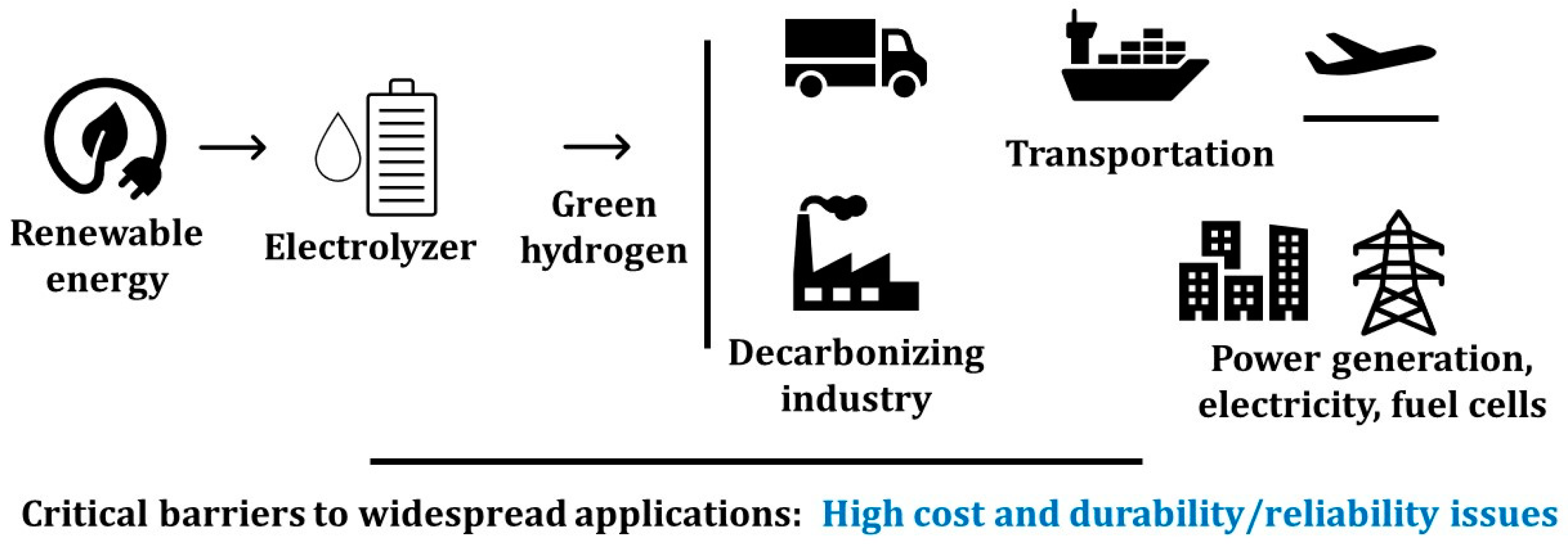
:1. Introduction
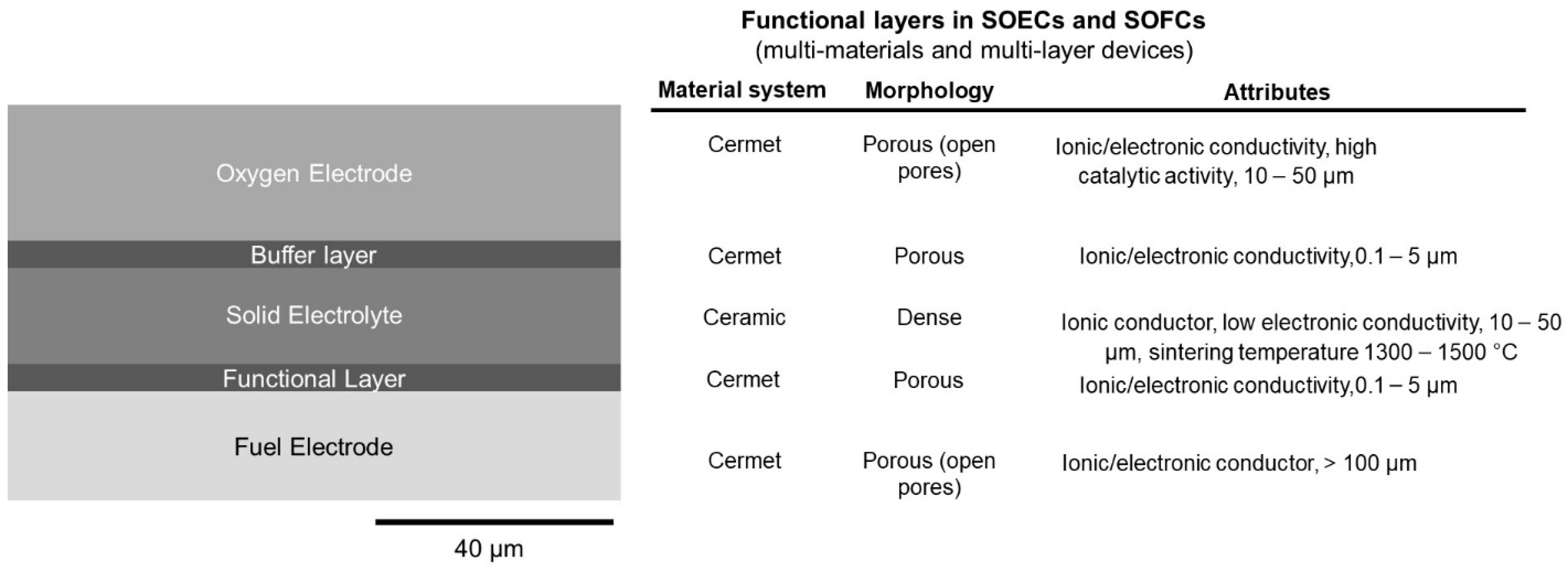
2. SOECs and SOFCs Components and Requirements
3. Reports in the Literature on Additive Manufacturing of SOFCs and SOECs
3.1. Inkjet Printing
3.2. Aerosol Jet Printing
3.3. Lithography-Based Printing (DLP and SL)
3.4. Robocasting
3.5. Other Potentially Applicable Processes
4. Opportunities and Challenges for AM Technologies
5. Outlook
Funding
Institutional Review Board Statement
Informed Consent Statement
Conflicts of Interest
References
- Achieving American Leadership in the Hydrogen Supply Chain; U.S. Department of Energy: Washington, DC, USA, 2022.
- High Temperature Electrolysis Manufacturing Workshop Summary Report, Hydrogen and Fuel Cell Technologies Office; U.S. Department of Energy: Washington, DC, USA, 2022.
- Hauch, A.; Küngas, R.; Blennow, P.; Hansen, A.B.; Hansen, J.B.; Mathiesen, B.V.; Mogensen, M.B. Recent advances in solid oxide cell technology for electrolysis. Science 2020, 370, eaba6118. [Google Scholar] [CrossRef] [PubMed]
- Water Electrolyzers and Fuel Cells Supply Chain: Supply Chain Deep Dive Assessment U.S. Department of Energy Response to Executive Order 14017, “America’s Supply Chains”; U.S. Department of Energy: Washington, DC, USA, 2022.
- Cramer, C.L.; Ionescu, E.; Graczyk-Zajac, M.; Nelson, A.T.; Katoh, Y.; Haslam, J.J.; Wondraczek, L.; Aguirre, T.G.; LeBlanc, S.; Wang, H.; et al. Additive manufacturing of ceramic materials for energy applications: Road map and opportunities. J. Eur. Ceram. Soc. 2022, 42, 3049–3088. [Google Scholar] [CrossRef]
- Ruiz-Morales, J.C.; Tarancón, A.; Canales-Vázquez, J.; Méndez-Ramos, J.; Hernández-Afonso, L.; Acosta-Mora, P.; Marín Rueda, J.R.; Fernández-González, R. Three dimensional printing of components and functional devices for energy and environmental applications. Energy Environ. Sci. 2017, 10, 846–859. [Google Scholar] [CrossRef] [Green Version]
- Weimar, M.R.; Chick, L.A.; Gotthold, D.W.; Whyatt, G.A. Cost Study for Manufacturing of Solid Oxide Fuel Cell Power Systems; Contract DE-AC05-76RL01830; Pacific Northwest National Laboratory: Richland, WA, USA, 2013. [Google Scholar]
- Pesce, A.; Hornés, A.; Núñez, M.; Morata, A.; Torrell, M.; Tarancón, A. 3D printing the next generation of enhanced solid oxide fuel and electrolysis cells. J. Mater. Chem. A 2020, 8, 16926–16932. [Google Scholar] [CrossRef]
- Bertei, A.; Tariq, F.; Yufit, V.; Ruiz-Trejo, E.; Brandon, N.P. Guidelines for the Rational Design and Engineering of 3D Manufactured Solid Oxide Fuel Cell Composite Electrodes. J. Electrochem. Soc. 2016, 164, F89–F98. [Google Scholar] [CrossRef]
- Chueh, C.-C.; Bertei, A. Thermo-mechanical analysis of 3D manufactured electrodes for solid oxide fuel cells. J. Eur. Ceram. Soc. 2021, 41, 497–508. [Google Scholar] [CrossRef]
- Zouridi, L.; Garagounis, I.; Vourros, A.; Marnellos, G.E.; Binas, V. Advances in Inkjet-Printed Solid Oxide Fuel Cells. Adv. Mater. Technol. 2022, 7, 2101491. [Google Scholar] [CrossRef]
- Deiner, L.J.; Reitz, T.L. Inkjet and Aerosol Jet Printing of Electrochemical Devices for Energy Conversion and Storage Adv. Eng. Mater. 2017, 19, 1600878. [Google Scholar] [CrossRef]
- Tai, X.Y.; Zhakeyev, A.; Wang, H.; Jiao, K.; Zhang, H.; Xuan, J. Accelerating Fuel Cell Development with Additive Manufacturing Technologies: State of the Art, Opportunities and Challenges. Fuel Cells 2019, 19, 636–650. [Google Scholar] [CrossRef]
- Rasaki, S.A.; Liu, C.; Lao, C.; Zhang, H.; Chen, Z. The innovative contribution of additive manufacturing towards revolutionizing fuel cell fabrication for clean energy generation: A comprehensive review. Renew. Sustain. Energy Rev. 2021, 148, 111369. [Google Scholar] [CrossRef]
- Zhang, X.; Wu, X.; Shi, J. Additive manufacturing of zirconia ceramics: A state-of-the-art review. J. Mater. Res. Technol. 2020, 9, 9029–9048. [Google Scholar] [CrossRef]
- Ambrosi, A.; Shi, R.R.S.; Webster, R.D. 3D-printing for electrolytic processes and electrochemical flow systems. J. Mater. Chem. A 2020, 8, 21902–21929. [Google Scholar] [CrossRef]
- Connor, P.A.; Yue, X.; Savaniu, C.D.; Price, R.; Triantafyllou, G.; Cassidy, M.; Kerherve, G.; Payne, D.J.; Maher, R.C.; Cohen, L.F.; et al. Tailoring SOFC Electrode Microstructures for Improved Performance. Adv. Energy Mater. 2018, 8, 1800120. [Google Scholar] [CrossRef]
- Xing, B.; Cao, C.; Zhao, W.; Shen, M.; Wang, C.; Zhao, Z. Dense 8 mol% yttria-stabilized zirconia electrolyte by DLP stereolithography. J. Eur. Ceram. Soc. 2020, 40, 1418–1423. [Google Scholar] [CrossRef]
- Shi, Y.; Cai, N.; Cao, T.; Zhang, J. High-Temperature Electrochemical Energy Conversion and Storage: Fundamentals and Applications; CRC Press: Boca Raton, FL, USA, 2018. [Google Scholar]
- Liu, Y.; Shao, Z.; Mori, T.; Jiang, S.P. Development of nickel based cermet anode materials in solid oxide fuel cells—Now and future. Mater. Rep. Energy 2021, 1, 100003. [Google Scholar] [CrossRef]
- Ferreira, V.J.; Wolff, D.; Hornés, A.; Morata, A.; Torrell, M.; Tarancón, A.; Corchero, C. 5 kW SOFC stack via 3D printing manufacturing: An evaluation of potential environmental benefits. Appl. Energy 2021, 291, 116803. [Google Scholar] [CrossRef]
- Shri Prakash, B.; Senthil Kumar, S.; Aruna, S.T. Properties and development of Ni/YSZ as an anode material in solid oxide fuel cell: A review. Renew. Sustain. Energy Rev. 2014, 36, 149–179. [Google Scholar] [CrossRef]
- Riyad, M.F.; Mahmoudi, M.; Minary-Jolandan, M. Manufacturing and Thermal Shock Characterization of Porous Yttria Stabilized Zirconia for Hydrogen Energy Systems. Ceramics 2022, 5, 472–483. [Google Scholar] [CrossRef]
- Brouzgou, A.; Demin, A.; Tsiakaras, P. Interconnects for Solid Oxide Fuel Cells. In Advances in Medium and High Temperature Solid Oxide Fuel Cell Technology; Boaro, M., Salvatore, A.A., Eds.; Springer International Publishing: Cham, Switzerland, 2017. [Google Scholar]
- Sulistyo, G.; Iwan, S. Progress in Glass-Ceramic Seal for Solid Oxide Fuel Cell Technology. J. Adv. Res. Fluid Mech. Therm. Sci. 2021, 82, 39–50. [Google Scholar] [CrossRef]
- Han, G.D.; Bae, K.; Kang, E.H.; Choi, H.J.; Shim, J.H. Inkjet Printing for Manufacturing Solid Oxide Fuel Cells. ACS Energy Lett. 2020, 5, 1586–1592. [Google Scholar] [CrossRef]
- Sukeshini, A.M.; Meisenkothen, F.; Gardner, P.; Reitz, T.L. Aerosol Jet® Printing of functionally graded SOFC anode interlayer and microstructural investigation by low voltage scanning electron microscopy. J. Power Sources 2013, 224, 295–303. [Google Scholar] [CrossRef]
- Farandos, N.M.; Li, T.; Kelsall, G.H. 3-D inkjet-printed solid oxide electrochemical reactors. II. LSM—YSZ electrodes. Electrochim. Acta 2018, 270, 264–273. [Google Scholar] [CrossRef]
- Farandos, N.M.; Kleiminger, L.; Li, T.; Hankin, A.; Kelsall, G.H. Three-dimensional Inkjet Printed Solid Oxide Electrochemical Reactors. I. Yttria-stabilized Zirconia Electrolyte. Electrochim. Acta 2016, 213, 324–331. [Google Scholar] [CrossRef] [Green Version]
- Sukeshini, A.M.; Cummins, R.; Reitz, T.L.; Miller, R.M. Inkjet Printing of Anode Supported SOFC: Comparison of Slurry Pasted Cathode and Printed Cathode. Electrochem. Solid-State Lett. 2009, 12, B176. [Google Scholar] [CrossRef]
- Shimada, H.; Ohba, F.; Li, X.; Hagiwara, A.; Ihara, M. Electrochemical Behaviors of Nickel/Yttria-Stabilized Zirconia Anodes with Distribution Controlled Yttrium-Doped Barium Zirconate by Ink-jet Technique. J. Electrochem. Soc. 2012, 159, F360–F367. [Google Scholar] [CrossRef]
- Han, G.D.; Neoh, K.C.; Bae, K.; Choi, H.J.; Park, S.W.; Son, J.-W.; Shim, J.H. Fabrication of lanthanum strontium cobalt ferrite (LSCF) cathodes for high performance solid oxide fuel cells using a low price commercial inkjet printer. J. Power Sources 2016, 306, 503–509. [Google Scholar] [CrossRef]
- Han, G.D.; Choi, H.J.; Bae, K.; Choi, H.R.; Jang, D.Y.; Shim, J.H. Fabrication of Lanthanum Strontium Cobalt Ferrite–Gadolinium-Doped Ceria Composite Cathodes Using a Low-Price Inkjet Printer. ACS Appl. Mater. Interfaces 2017, 9, 39347–39356. [Google Scholar] [CrossRef]
- Li, C.; Chen, H.; Shi, H.; Tade, M.O.; Shao, Z. Green fabrication of composite cathode with attractive performance for solid oxide fuel cells through facile inkjet printing. J. Power Sources 2015, 273, 465–471. [Google Scholar] [CrossRef]
- Yashiro, N.; Usui, T.; Kikuta, K. Application of a thin intermediate cathode layer prepared by inkjet printing for SOFCs. J. Eur. Ceram. Soc. 2010, 30, 2093–2098. [Google Scholar] [CrossRef]
- Sukeshini, M.A.; Cummins, R.; Reitz, T.L.; Miller, R.M. Ink-Jet Printing: A Versatile Method for Multilayer Solid Oxide Fuel Cells Fabrication. J. Am. Ceram. Soc. 2009, 92, 2913–2919. [Google Scholar] [CrossRef]
- Rosa, M.; Zielke, P.; Kiebach, R.; Costa Bassetto, V.; Lesch, A.; Esposito, V. Printing of NiO-YSZ nanocomposites: From continuous synthesis to inkjet deposition. J. Eur. Ceram. Soc. 2019, 39, 1279–1286. [Google Scholar] [CrossRef]
- Li, C.; Shi, H.; Ran, R.; Su, C.; Shao, Z. Thermal inkjet printing of thin-film electrolytes and buffering layers for solid oxide fuel cells with improved performance. Int. J. Hydrogen Energy 2013, 38, 9310–9319. [Google Scholar] [CrossRef]
- Tomov, R.I.; Krauz, M.; Jewulski, J.; Hopkins, S.C.; Kluczowski, J.R.; Glowacka, D.M.; Glowacki, B.A. Direct ceramic inkjet printing of yttria-stabilized zirconia electrolyte layers for anode-supported solid oxide fuel cells. J. Power Sources 2010, 195, 7160–7167. [Google Scholar] [CrossRef]
- Gadea, C.; Hanniet, Q.; Lesch, A.; Marani, D.; Jensen, S.H.; Esposito, V. Aqueous metal–organic solutions for YSZ thin film inkjet deposition. J. Mater. Chem. C 2017, 5, 6021–6029. [Google Scholar] [CrossRef] [Green Version]
- Esposito, V.; Gadea, C.; Hjelm, J.; Marani, D.; Hu, Q.; Agersted, K.; Ramousse, S.; Jensen, S.H. Fabrication of thin yttria-stabilized-zirconia dense electrolyte layers by inkjet printing for high performing solid oxide fuel cells. J. Power Sources 2015, 273, 89–95. [Google Scholar] [CrossRef]
- Masciandaro, S.; Torrell, M.; Leone, P.; Tarancón, A. Three-dimensional printed yttria-stabilized zirconia self-supported electrolytes for solid oxide fuel cell applications. J. Eur. Ceram. Soc. 2019, 39, 9–16. [Google Scholar] [CrossRef] [Green Version]
- Wei, L.; Zhang, J.; Yu, F.; Zhang, W.; Meng, X.; Yang, N.; Liu, S. A novel fabrication of yttria-stabilized-zirconia dense electrolyte for solid oxide fuel cells by 3D printing technique. Int. J. Hydrogen Energy 2019, 44, 6182–6191. [Google Scholar] [CrossRef]
- Young, D.; Sukeshini, A.M.; Cummins, R.; Xiao, H.; Rottmayer, M.; Reitz, T. Ink-jet printing of electrolyte and anode functional layer for solid oxide fuel cells. J. Power Sources 2008, 184, 191–196. [Google Scholar] [CrossRef]
- Jang, I.; Kelsall, G.H. Fabrication of 3D NiO-YSZ structures for enhanced performance of solid oxide fuel cells and electrolysers. Electrochem. Commun. 2022, 137, 107260. [Google Scholar] [CrossRef]
- Huang, W.; Finnerty, C.; Sharp, R.; Wang, K.; Balili, B. High-Performance 3D Printed Microtubular Solid Oxide Fuel Cells. Adv. Mater. Technol. 2017, 2, 1600258. [Google Scholar] [CrossRef]
- Sobolev, A.; Stein, P.; Borodianskiy, K. Synthesis and characterization of NiO colloidal ink solution for printing components of solid oxide fuel cells anodes. Ceram. Int. 2020, 46, 25260–25265. [Google Scholar] [CrossRef]
- Pirou, S.; Talic, B.; Brodersen, K.; Hauch, A.; Frandsen, H.L.; Skafte, T.L.; Persson, Å.H.; Høgh, J.V.T.; Henriksen, H.; Navasa, M.; et al. Production of a monolithic fuel cell stack with high power density. Nat. Commun. 2022, 13, 1263. [Google Scholar] [CrossRef]
- De Hazan, Y.; Heinecke, J.; Weber, A.; Graule, T. High solids loading ceramic colloidal dispersions in UV curable media via comb-polyelectrolyte surfactants. J. Colloid Interface Sci. 2009, 337, 66–74. [Google Scholar] [CrossRef] [PubMed]
- Anelli, S.; Rosa, M.; Baiutti, F.; Torrell, M.; Esposito, V.; Tarancón, A. Hybrid-3D printing of symmetric solid oxide cells by inkjet printing and robocasting. Addit. Manuf. 2022, 51, 102636. [Google Scholar] [CrossRef]
- Dermeik, B.; Travitzky, N. Laminated Object Manufacturing of Ceramic-Based Materials. Adv. Eng. Mater. 2020, 22, 2000256. [Google Scholar] [CrossRef]
- Merino, R.I.; Laguna-Bercero, M.A.; Lahoz, R.; Larrea, Á.; Oliete, P.B.; Orera, A.; Peña, J.I.; Sanjuán, M.L.; Sola, D. Laser processing of ceramic materials for electrochemical and high temperature energy applications. Boletín Soc. Española Cerámica Vidr. 2022, 61, S19–S39. [Google Scholar] [CrossRef]
- Salari, F.; Badihi Najafabadi, A.; Ghatee, M.; Golmohammad, M. Hybrid additive manufacturing of the modified electrolyte-electrode surface of planar solid oxide fuel cells. Int. J. Appl. Ceram. Technol. 2020, 17, 1554–1561. [Google Scholar] [CrossRef]
- Bhattacharya, M.; Basak, T. A review on the susceptor assisted microwave processing of materials. Energy 2016, 97, 306–338. [Google Scholar] [CrossRef]
- Singh, M.; Zappa, D.; Comini, E. Solid oxide fuel cell: Decade of progress, future perspectives and challenges. Int. J. Hydrog. Energy 2021, 46, 27643–27674. [Google Scholar] [CrossRef]
- Tucker, M.C. Progress in metal-supported solid oxide fuel cells: A review. J. Power Sources 2010, 195, 4570–4582. [Google Scholar] [CrossRef]
- Tucker, M.C. Progress in metal-supported solid oxide electrolysis cells: A review. Int. J. Hydrogen Energy 2020, 45, 24203–24218. [Google Scholar] [CrossRef]
- Shaukat, U.; Rossegger, E.; Schlögl, S. A Review of Multi-Material 3D Printing of Functional Materials via Vat Photopolymerization. Polymers 2022, 14, 2449. [Google Scholar] [CrossRef] [PubMed]
- MacDonald, E.; Wicker, R. Multiprocess 3D printing for increasing component functionality. Science 2016, 353, aaf2093. [Google Scholar] [CrossRef] [PubMed]


| Printing Process | Advantages | Limitations | Considerations |
|---|---|---|---|
| Inkjet |
|
|
|
| Lithography based (SL and DLP) |
|
|
|
| Printed Component | Printing Method | Notes | Reference |
|---|---|---|---|
| NiO-YSZ interlayer and YSZ electrolyte layer | Inkjet | Both layers were ~6 μm thick. Sintering temperature 1375–1400 °C. Open circuit voltages ranged from 0.95 to 1.06 V, and a maximum power density of 0.175 W·cm−2 was achieved at 750 °C. | [44] |
| Entire anode-supported cell | Inkjet | Achieved power output of 730 mW·cm−2 at 650 °C and a low degradation rate of 0.2 mV·h−1. | [26] |
| YSZ electrolyte and Micro-pillar anode | Inkjet | A pillar height of ~28 µm was obtained for 90-layer printing. YSZ electrolyte was sintered at 1450 °C. | [45] |
| YSZ electrolyte and YSZ-LSM electrode | Inkjet | YSZ electrolyte and YSZ-LSM electrode were 9 and 20 µm thick, respectively. At 788 °C, the peak fuel cell power density was 0.69 W·cm−2, and at a cell potential difference of 1.5 V. | [28] |
| Microtubular cells (anode (NiO-YSZ), electrolyte (YSZ) and cathode layers) | Inkjet | More than 4000 h of long-term operation at a constant current of 18.5 A and at 788 °C, the peak fuel cell power density was 0.69 W cm−2, and at a cell potential difference of 1.5 V. | [46] |
| YSZ electrolyte | Inkjet | 23 mm thick planar electrolyte. A current density of −0.78 A cm−2 was obtained. Sintered at 1500 °C. | [29] |
| YSZ electrolyte | Inkjet | 150 nm films were obtained. | [40] |
| YSZ electrolyte | Inkjet | 1.2 µm film was obtained. Peak power density above 1.5 W·cm−2 at 800 °C was obtained. Sintered at 1300 °C. | [41] |
| YSZ electrolyte | Inkjet | Power density of 170 mW·cm−2 at 800 °C was obtained. | [39] |
| Electrolyte and buffering (SDC) layers | Inkjet (thermal) | Peak power density (PPD) of 860 mW·cm−2 at 800 °C. Sintered at 1400 °C. | [38] |
| NiO anode | Inkjet | Calcinated in air at 900 °C. | [47] |
| Nio-YSZ | Inkjet | Sintered at 1295 °C. | [37] |
| Anode interlayer and electrolyte | Inkjet | Sintered at 1400 °C. Open circuit voltage of 1.1 V around 800 °C. A maximum power density of 500 mW·cm−2 was achieved at 850 °C. | [36] |
| LSCF-GDC composite cathode | Inkjet | Power output of over 570 mW cm−2 at 650 °C was obtained. Sintered at 950 °C. | [33] |
| Intermediate cathode layer | Inkjet | Maximum power density of 0.71 W/cm2 at 600 °C was obtained. Sintered at 1000 °C. | [35] |
| YSZ pillar electrolyte | Inkjet (hybrid with tape casting) | Sintered at 1200 °C. | [53] |
| Composite cathode | Inkjet | PPD as high as 940 mW cm−2 at 750 °C was obtained. Calcined at 1000 °C. | [34] |
| Nio-YSZ anode layer, YSZ electrolyte and LSM cathode layer | Inkjet | An open–circuit voltage of 1.1 V and a maximum power density of 430–460 mW/cm2 at 850°C was obtained. Sintered at 1200 °C. | [30] |
| LSCF cathode | Inkjet | A maximum peak power density of 377 mW cm−2 at 600 °C was obtained. Sintered at 950 °C. | [32] |
| Ni-YSZ anode | Inkjet | Sintered at 1400 °C. Anode with distribution-controlled Yttrium-doped Barium Zirconate. | [31] |
| Electrolyte and symmetric electrodes | Hybrid inkjet and robocasting | YSZ electrolyte by inkjet and LSM-YSZ symmetric electrodes by robocasting. | [50] |
| YSZ electrolyte and functionally graded anode interlayers | Aerosol Jet Printing | Graded composite anode interlayer was obtained. Anode interlayer was sintered at 1400 °C. | [27] |
| YSZ electrolyte | DLP | An open circuit voltage of approximately 1.04 V and a peak power density up to 176 mW cm−2 at 850 °C was obtained. Sintered at 1550 °C. | [43] |
| YSZ electrolyte | DLP | Sintered at 1450 °C. | [42] |
| YSZ electrolyte (corrugated surface) | DLP | Sintered at 1300 °C. | [8] |
| YSZ electrolyte | DLP | Sintered at 1450 °C. | [18] |
| Challenges | Opportunities |
|---|---|
| 1. Eliminate or reduce stacking and lamination steps and enhance durability |
|
| 2. Facilitate co-sintering |
|
| 3. Enable lower temperature operation |
|
| 4. Enable high-volume production and lower total cost |
|
| 5. Enable complex geometries, different cell configurations and larger cell size |
|
| 6. Enable morphology (mostly pores) control |
|
| 7. Enable “true” multi-material, multiscale 3D printing |
|
| 8. Enable robotic-assisted multi-printer process |
|
| 9. Incorporate computational design and modeling |
|
Publisher’s Note: MDPI stays neutral with regard to jurisdictional claims in published maps and institutional affiliations. |
© 2022 by the author. Licensee MDPI, Basel, Switzerland. This article is an open access article distributed under the terms and conditions of the Creative Commons Attribution (CC BY) license (https://creativecommons.org/licenses/by/4.0/).
Share and Cite
Minary-Jolandan, M. Formidable Challenges in Additive Manufacturing of Solid Oxide Electrolyzers (SOECs) and Solid Oxide Fuel Cells (SOFCs) for Electrolytic Hydrogen Economy toward Global Decarbonization. Ceramics 2022, 5, 761-779. https://doi.org/10.3390/ceramics5040055
Minary-Jolandan M. Formidable Challenges in Additive Manufacturing of Solid Oxide Electrolyzers (SOECs) and Solid Oxide Fuel Cells (SOFCs) for Electrolytic Hydrogen Economy toward Global Decarbonization. Ceramics. 2022; 5(4):761-779. https://doi.org/10.3390/ceramics5040055
Chicago/Turabian StyleMinary-Jolandan, Majid. 2022. "Formidable Challenges in Additive Manufacturing of Solid Oxide Electrolyzers (SOECs) and Solid Oxide Fuel Cells (SOFCs) for Electrolytic Hydrogen Economy toward Global Decarbonization" Ceramics 5, no. 4: 761-779. https://doi.org/10.3390/ceramics5040055