
Development of a Digital Well Management System

Scientific and Educational Center of Geology and Development of Oil and Gas Fields, Perm National Research Polytechnic University, 614990 Perm, Russia
*
Author to whom correspondence should be addressed.
Appl. Syst. Innov. 2023, 6(1), 31; https://doi.org/10.3390/asi6010031
Submission received: 31 January 2023
/
Revised: 7 February 2023
/
Accepted: 13 February 2023
/
Published: 17 February 2023
(This article belongs to the Section Control and Systems Engineering)
Abstract
:The modern oil industry is characterized by a strong trend towards the digitalization of all technological processes. At the same time, during the transition of oil fields to the later stages of development, the issues of optimizing the consumed electricity become relevant. The purpose of this work is to develop a digital automated system for distributed control of production wells using elements of machine learning. The structure of information exchange within the framework of the automated system being created, consisting of three levels of automation, is proposed. Management of the extractive fund is supposed to be based on the work of four modules. The “Complications” module analyzes the operation of oil wells and peripheral equipment and, according to the embedded algorithms, evaluates the cause of the deviation, ways to eliminate it and the effectiveness of each method based on historical data. The “Power Consumption Optimization” module allows integrating algorithms into the well control system to reduce energy consumption by maintaining the most energy-efficient operation of pumping equipment or optimizing its operation time. The module “Ensuring the well flow rate” allows you to analyze and determine the reasons for the decrease in production rate, taking into account the parameters of the operation of adjacent wells. The Equipment Anomaly Prediction module is based on machine learning and helps reduce equipment downtime by predicting and automatically responding to potential deviations. As a result of using the proposed system, many goals of the oil company are achieved: specific energy consumption, oil shortages, and accident rate are reduced, while reducing the labor costs of engineering and technological personnel for processing the operation parameters of all process equipment.
1. Introduction
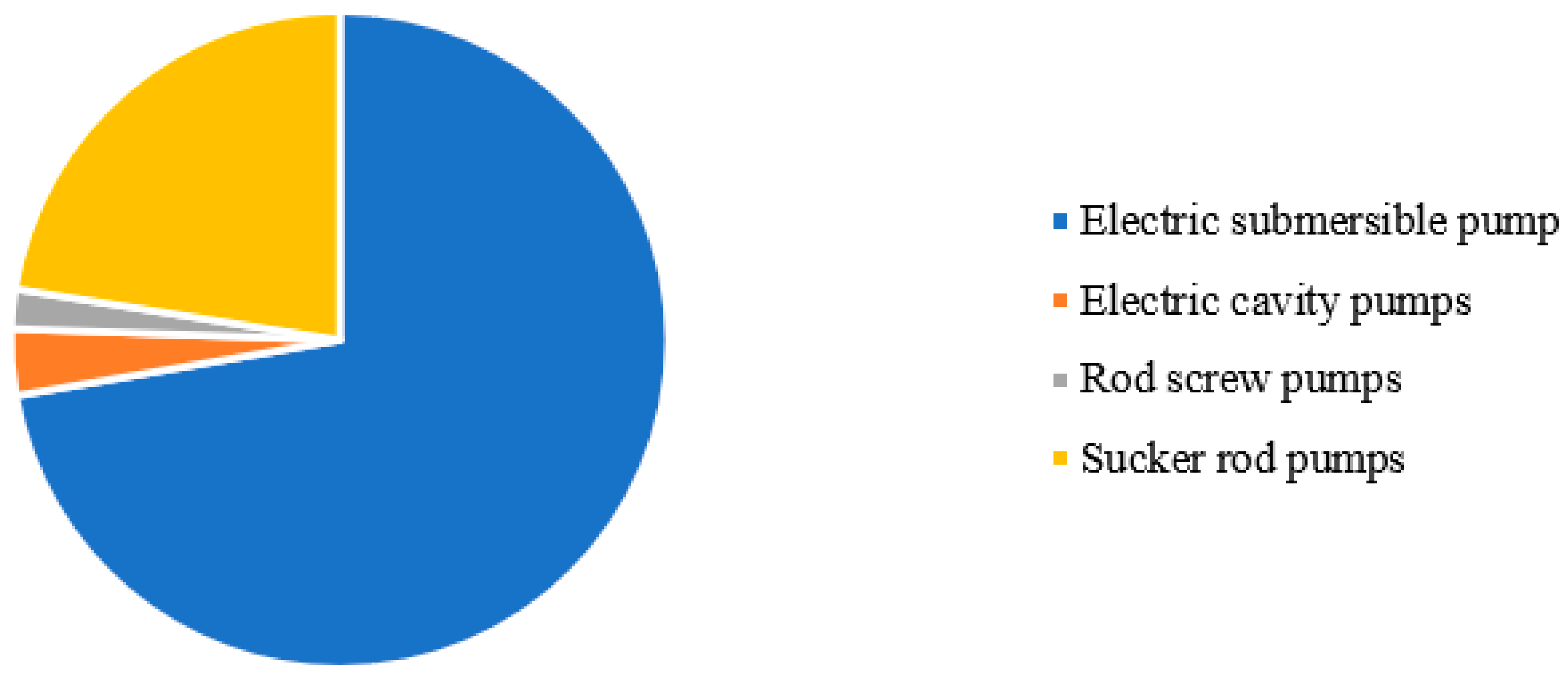
Currently, many oil fields, including those in the Perm Krai, are moving to the late stages of development, which leads to a decrease in well flow rates, an increase in water cut and an increase in operating costs for production [1,2,3]. In this regard, the actual direction is the optimization of energy consumption at the oil field, the reduction of oil shortages and the increase in the time between failures of equipment [4,5]. According to the data given in [6], the share of artificial lift in the energy consumption structure of an oil field exceeds 55%. It is worth noting that less than 1% of wells in the Perm region are operated by the flowing method. Consider the composition of the production well stock of the northern group of fields in the Perm Krai, shown in Figure 1 [7,8].
According to this distribution, most wells are operated by electric submersible pumps (ESP) and sucker rod pumps (SRP). To control the downhole pumping equipment, control stations are used—complexes that allow preventing emergencies, adjusting the speed and recording data from the telemetry system. Most modern control stations have advanced functionality, represented by the possibility of smooth acceleration, braking of the electric motor, automatic restart when the parameters return to the working area, etc. [9,10].
The modern oil industry is characterized by a strong trend towards digitalization, automation of all technological processes and the introduction of artificial intelligence in all components of oil production, transport and refining [11,12,13]. Thus, the development and use of intelligent control stations (ICS) is currently underway [14,15]. These control stations are significantly superior to the currently used classical control stations. Their main advantage is the intelligent optimization of downhole pumping equipment operation, reduction of specific energy consumption, recording and analysis of well and downhole pumping equipment operation parameters, minimization of submersible electric motor (SEM) emergency shutdowns due to high-quality forecasting and automatic response to deviations [16,17,18]. There is a need to develop group control stations that allow you to simultaneously control the operation of several wells on one pad, as well as other oilfield equipment [19,20]. Such equipment may include an automatic group metering unit, wellhead inhibitor dosing units, semi-automatic dewaxing units and automatic devices for cleaning pipe [21]. Most of the control stations being developed provide functions for analyzing data received from downhole pressure gauges, a telemetry system and entered into the system by engineering and technical personnel. The operation of these control stations does not involve taking into account the characteristics of the reservoir, well, or pump. The history of operation is not taken into account and predictive data analysis is not performed. As part of this work, a modern digital automated system for managing and optimizing the operation of the oil well stock (ACS) is presented. This system offers a new direction in the field of oil well cluster management, combines developments in the field of digital model of oil-producing facilities and artificial intelligence for process control.
The rest of this paper is organized as follows: Section 2 describes the general concept of well cluster management and applied mathematical models. Section 3 describes the developed ACS modules, as well as experience with one of the modules. Section 4 offers a discussion of the application of the developed ACS.
2. Materials and Methods
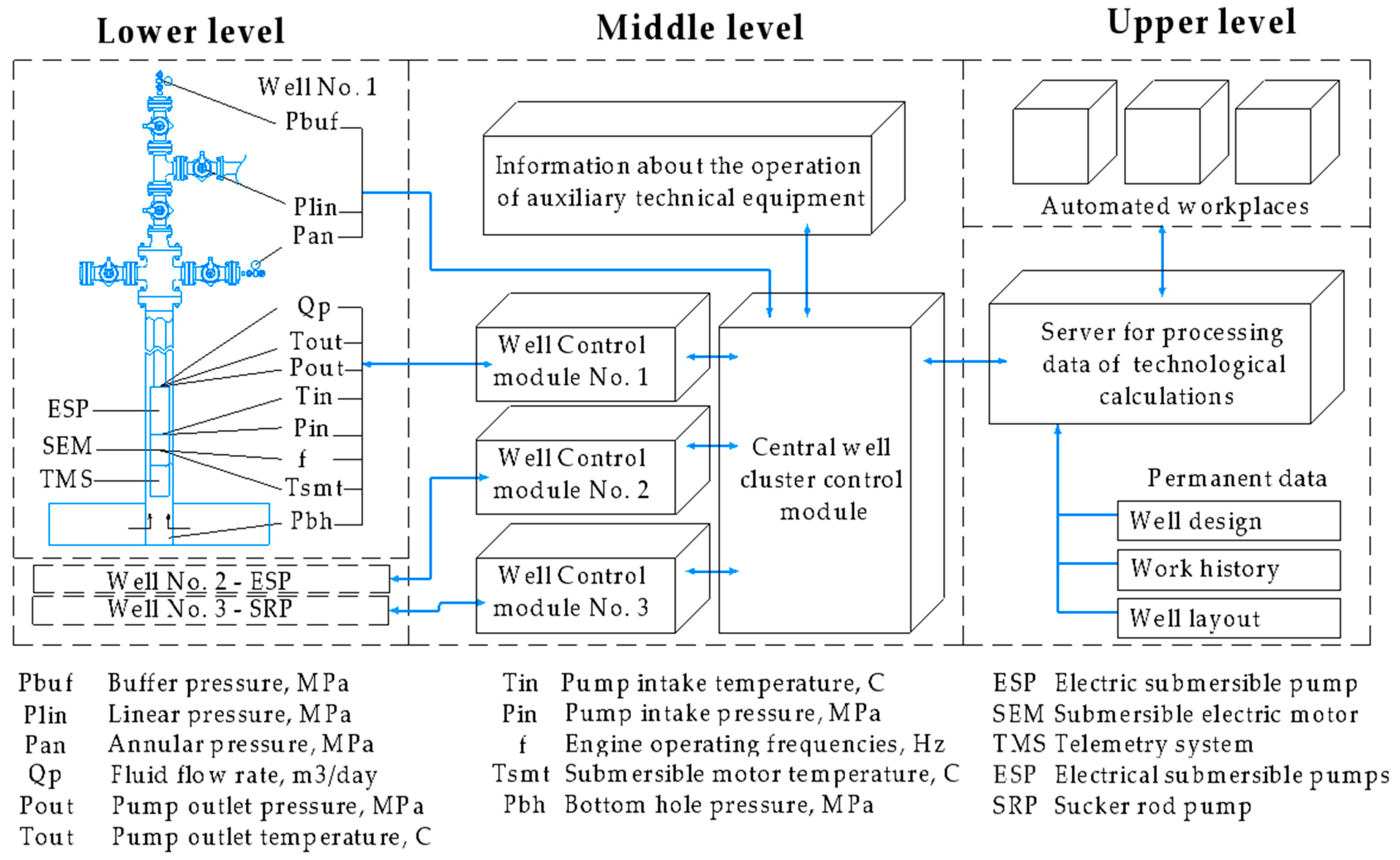
Consider the case when a production well is operated by an ESP with a modern control station. The information coming from the measuring instruments to the control station is analyzed to turn off the wells when the parameter values go out of the allowable range. Below, a more modern way of exchanging information with an increase in the number of its sources and the use of machine learning elements is proposed for more efficient management of a production well. The information exchange scheme is shown in Figure 2.
Within the framework of the proposed scheme, a decomposition of the control station into constant and variable parts is proposed, similar to the proposal in [22]. In this case, the well control module becomes a permanent part of the control station, and the variable parts (central well cluster control module, server, workstations) of all wells are combined into an industrial data transmission network [23,24]. The sources of information about the operation of the well and other equipment are digital sensors of pressure, temperature, distance, etc., installed at technological facilities and transmitting information wirelessly or wirelessly. The collection of information about the operation of fishing equipment is carried out via an ESP cable sent directly to ACS. ACS can be divided into three levels of automation: “lower”, “middle” and “upper”. Let’s consider each level separately.
The lower level of automation includes analog and discrete sensors, shut-off and control valves, actuators and implements the functions of converting physical parameters into electrical and digital signals and vice versa. The middle level is the level of pad and downhole programmable logic controllers (PLC)—designed to collect information from the process equipment of a well pad, control submersible pumping equipment. It includes data transmission modules, converters, switches, controllers. One production well cluster equipped with ECP, SRP and ESP is equipped with several well control modules and one main well cluster control module (WCS). The well control module consists of a power unit and a PLC. The main well cluster control module collects and analyzes data from the equipment that is part of the well cluster and transfers data to the upper-level system, and also ensures the optimal operation of the production equipment by analyzing the measured and calculated parameters using the mathematical model of the well. Optimization of the operating mode occurs by maintaining the operating mode of the well by frequency control (described in Section 2.1.2 and Section 2.1.3).
The WCS contains a group controller and a PLC for each production well, which implement software and automatic control of the energy-efficient operation of downhole pumping equipment in continuous, periodic and short-term periodic well operation modes. Thanks to the operation of the WCS, it is also possible to adjust the operating parameters of peripheral equipment, based on the operating mode of production wells. So, when identifying the intensive formation of paraffin deposits, it is possible to change the operating mode of automatic devices for cleaning pipe to adjust the interval or frequency of cleaning the pipe, change the performance of wellhead inhibitor dosing units.
The upper level includes workstations for operational personnel, data processing servers and implements information, computing and control functions through software. Top-level software provides mathematical modeling of production parameters, according to specified algorithms well (presented in Section 2.1), forecasting the formation of complications in oil production (Section 3.1), quantitative calculation of produced products (Section 3.3), automatic elimination of technological deviations in the operation of downhole pumping and surface equipment (Section 3.3), forecasting degradation of downhole pumping equipment using predictive analysis (Section 3.4). The upper level software is represented by 4 modules described below. The ACS operates in two modes: “advisor” mode and automatic mode. When operating in the first mode, the signals issued from the ACS will be advisory in nature and sent to the operator’s workstation in the form of notifications. When operating in automatic mode, the ACS does not require coordination of the generated signal, it is the control signal.
Based on the analysis of fishing experience, it was decided to divide the control system into 4 modules: “Complications”, “Electricity Consumption Optimization”, “Ensuring the flow rate of the well”, “Prediction of deviations in equipment operation”.
2.1. Mathematical Model of the Well
As a part of the analysis of the well operation parameters, the “nodal analysis” technique id used, which is described in detail in [25,26]. This technique involves the division of the fluid production process into two blocks: the fluid inflow from the formation into the well and the movement of fluid along the wellbore. A characteristic is calculated for each system. For oil inflow into wells—Inflow Performance Relationship. For oil production—vertical lift performance. The point of intersection of these curves is the optimal point for oil production in a given well. The main task of the subsoil user is to ensure the operation of the well in optimal conditions. As a part of this analysis, the optimization of well operation is carried out taking into account 3 models:
2.1.1. Liquid Model
In the framework of this work, the Black Oil model was used to describe the physical properties of a three-phase liquid. This model is a simplified model of reservoir fluid, consisting of oil, associated petroleum gas and water, and with the help of correlation dependencies it allows to calculate the following fluid characteristics: density, viscosity, gas solubility, compressibility factor, z-factor, etc. [27].
2.1.2. Well Inflow Model
The model of oil inflow into the reservoir is represented as a dependence of the production rate on the created drawdown. To determine the shape of the curve of oil inflow into the well, studies are carried out at field facilities to remove the indicator curve. The most common models of oil inflow into a well are [28,29]:
- Linear inflow model (Darcy model)
- Vogel model
- Vogel model adjusted for well water content
If there is a known curve of oil inflow into the well, to determine the theoretical flow rate, it is necessary to build a well characteristic. The well characteristics are estimated using the Hagedorn and Brown correlation [30]. This model was chosen due to its versatility, so in [31] a comparison of various multiphase flow models was carried out, and only this model shows acceptable accuracy for various flow regimes. Based on the results of calculating the curve of oil inflow into the well and the characteristics into the well, it is possible to plot these curves in a single coordinate system and determine the operating point.
2.1.3. Submersible Equipment Model
The ESP operating parameters are changed according to the ratings provided for each pump used. So, each pump has a zone of optimal operation, characterized by maximum efficiency. The regulation of the ESP operation is performed by one of two methods—installing a choke to increase the pressure at the wellhead or frequency regulation [32,33]. The parameters of operation and energy consumption of the pump depend on the operating conditions, passport characteristics and properties of the pumped liquid. In works [34,35], empirically and theoretically created algorithms for recalculating the head, flow, efficiency and power of the pump from the properties of the pumped liquid are presented. The algorithm for calculating and optimizing the energy consumption of a pump is presented in [36].
3. Results
3.1. Module “Complications”
The process of extraction and collection of hydrocarbons is accompanied by a number of technological complications, namely: the formation of wax deposition, the formation of high-viscosity emulsions, salt formation, corrosion of oilfield equipment, the presence of mechanical impurities in the product, and a high gas factor [37]. The operation of the “Complications” module involves constant monitoring of the operation parameters of an oil well and peripheral equipment in order to identify the occurrence of a particular complication. This module will allow:
- Reduce operating costs due to the consumption of chemicals to deal with complications, optimize the operation of auxiliary equipment, reduce well maintenance costs, and reduce labor costs for maintenance personnel;
- Reduce downtime of technological equipment by optimally selecting the parameters of its operation, preventing operation in an inefficient mode, optimizing methods for dealing with complications and preventing accidents.
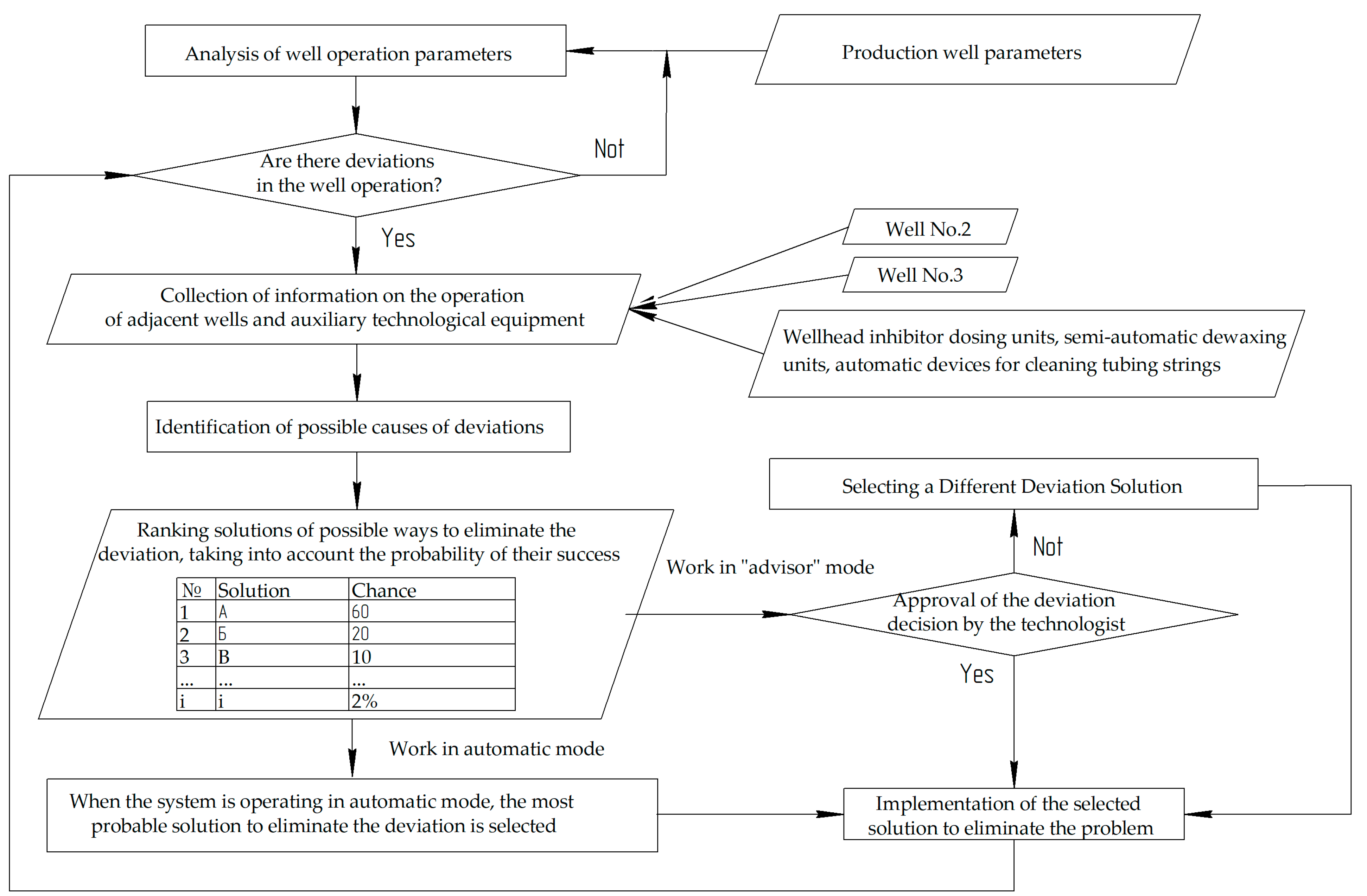
The operation scheme of the “Complications” module is shown in Figure 3.
If the operating parameters of the production well deviate from the base value by more than the established limit, the process of identifying the cause of the deviation starts. To do this, the automated control system analyzes the current and archived data on the operation of the well, the parameters of the operation of other production wells on the pad, auxiliary technological equipment to determine the possible causes of the deviation. After collecting information, a special algorithm of actions is launched for each deviation in the operation of the well. An example of this algorithm is shown in Figure 4. Based on the results of this algorithm, a list of possible reasons for the deviation is formed, as well as ways to eliminate it, taking into account the probability of success. These system operation algorithms are formed at the stage of its creation. Over time, the system analyzes the deviation processing data and refines the decision rating based on the success and frequency of the well event. Then, depending on the mode of operation (“advisor” or automatic), the action to eliminate the deviation is coordinated or this action is performed automatically. Based on the results of the algorithm execution, the system switches to the mode of monitoring the parameters of the well operation. If the deviation in the well operation persists, the algorithm is repeated, and the absence of the effect of the previously selected action to eliminate the deviation is considered.
Clogging of equipment with wax deposits, salts, hydrates is identified by changing the load on the electric motor, deviation of the well flow rate, SEM temperature, pressure at the inlet and outlet of the pump, and other parameters [38,39]. Due to the formation of deposits in a well equipped with a sucker rod pump, it is possible to hang the rods, reduce the fluid flow rate, increase the load on the polished rod, and change the dynamometer chart [40,41]. The formation of highly viscous emulsions affects the resistance of the liquid to rise. Due to the formation of high-viscosity emulsions, the loads on downhole pumping equipment increase, due to changes in the rheological properties of oil, the well characteristics change and the operating point of the “pump-well” system shifts [42]. The complication of well operation in the form of intense corrosion of oilfield equipment before the fact of leakage of the pipe is not controlled by ACS. In this case, the identification of the fact of through corrosion is carried out by changing the load of the submersible motor, the well flow rate, the pressure at the pump intake, the temperature of the engine and fluid, the dynamics of changes in wellhead pressures and other parameters. A high GOR during oil production also leads to unstable operation of equipment, the occurrence of gas plugs, and a change in the flow regime [43]. When operating a well with electric centrifugal pumps, this leads to their shutdown due to underload, and when operating with rod pumps, a drop in production due to a decrease in the pump filling factor.
Let us consider the situation when the reason for the deviation of the operating parameters is identified at a production well: “wax deposition formation”. To eliminate this deviation, the following actions are possible:
- Changing the operating mode of the device for mechanical cleaning of the well (if any);
- Carrying out forced removal of deposits mechanically;
- Changing the operation parameters of surface equipment for chemical dosing (if any);
- Carrying out routine maintenance (flushing);
- An increase in temperature or a change in the operating mode of the heating cable line or induction heaters.
At the stage of system development, the assessment of the probability of a particular deviation is carried out by experts with the involvement of engineering and technical personnel and taking into account operating experience. With continued use, the system learns from historical data and ranks the probability of deviation and how to eliminate it, as described earlier.
As a result of the operation of this module, it becomes possible to prevent accidents associated with the formation of deposits and the automatic selection of methods for dealing with deposits. Thus, when the temperature and pressure on the submersible pump increase and the well is complicated by the formation of wax deposits, the system automatically recommends well treatment to prevent an accident.
3.2. Module “Electricity Consumption Optimization
As mentioned earlier, mechanical oil production is the most energy-intensive process in the oil field. Reduction of specific energy consumption per unit of extracted product is an important direction in the work of the subsoil user. The module “Optimization of electricity consumption” will allow, when managing the production well stock, to ensure the minimum specific energy consumption by:
- Automatic maintenance of the operating point for downhole equipment;
- Implementation of automatic calculation and change of operating mode (transition from periodic to continuous mode and vice versa);
- Optimization of the time and mode of operation during the day of the periodic stock of wells;
- Ensuring the planned average daily flow rate with minimal energy consumption during hours of high cost of electricity;
- Optimization of power consumption of the sucker rod pump installation when the plunger moves down.
As part of the implementation of this module, all actions for managing the production fund are aimed at assessing and achieving the minimum specific energy consumption for the production of a unit of well production. This module makes it possible to estimate, taking into account the parameters of the reservoir-well system, the recommended level of well production, which ensures the minimization of energy consumption within the potential of the reservoir and downhole pumping equipment. When optimizing the operation of periodic wells, it is proposed to calculate the start time based on the loading of the collection and transport system in order to reduce backpressure and friction pressure losses with large volumes of pumping through the system. The module provides for the implementation of the function of reducing the instantaneous production rate of wells during hours of high tariff rates for electricity, while ensuring the planned average daily production. The minimum required productivity of downhole equipment is estimated, which ensures the production of well products in the allowable range of specific energy consumption. It is possible to adapt the speed of submersible electric motors based on the recommended intervals for the maximum and minimum load on the enterprise’s power grid, taking into account the mutual influence of wells in the collection system.
When working with a sucker rod pump unit, pumping cycles are optimized by slowing down and accelerating the engine when passing the top and bottom dead centers, respectively. It is possible to optimize the operation of the electric motor due to the algorithm for avoiding the generator mode—taking into account the technological feasibility, the minimum descent speed and the permissible range of the plunger ascent speed are determined.
An example of the application of the technique will be presented in Section 3.5. In general, optimizing the operation of the well allows you to maintain its operation at maximum efficiency in conditions of constantly changing operating conditions. Also, the operation of the periodic well stock can be optimized to reduce friction pressure losses. So, if there are 4 wells on the well cluster in a periodic mode, the system will offer to extract oil in the most debit wells at night, during which the energy cost is lower, and distribute the work of the remaining wells during the day to reduce the friction pressure consumption.
3.3. Module “Ensuring the Flow Rate of the Well”
The most important technological parameter of a production well is its production rate. One of the main tasks of a subsoil user is to maintain this parameter at the regime level required for the efficient and planned development of an oil field. Well flow rate assurance module provides:
- Automatic control of actual measurements and well flow rate management based on information from an automatic group metering unit and the result of a virtual flow rate measurement;
- Automatic control of the filling factor of the SRP pump and regulation of the flow rate of the installations;
- Identification of flow rate deviations from regime values, issuance of an informational (in the “advisor” mode) or a control signal (in the automatic mode of operation) aimed at restoring the flow rate.
The first point involves the analysis of data with an automatic group metering unit on the flow rate of wells, and if they deviate from the regime value by more than the set value, the activation of the “Virtual flow meter” function to clarify the correct operation of the automatic group metering unit. If the calculated value of the flow rate corresponds to the measured one, then it is necessary to identify the cause of the deviation (functionality of the “Complications” module). If the calculated value of the flow rate differs from the measured value of the automatic group metering unit, control continues, a recommendation is issued for steaming, revision of the automatic group metering unit and re-measurement.
The second point involves the registration of indirect parameters of operation by installing a sucker rod pump to calculate the value of the filling factor and timely control this value. Provides a change in the frequency of rotation of the pumping unit drive motor when the pump fill factor drops below the specified value.
The third point involves analyzing the deviation of the well flow rate from the regime value, determining the cause of such a deviation, and restoring the flow rate.
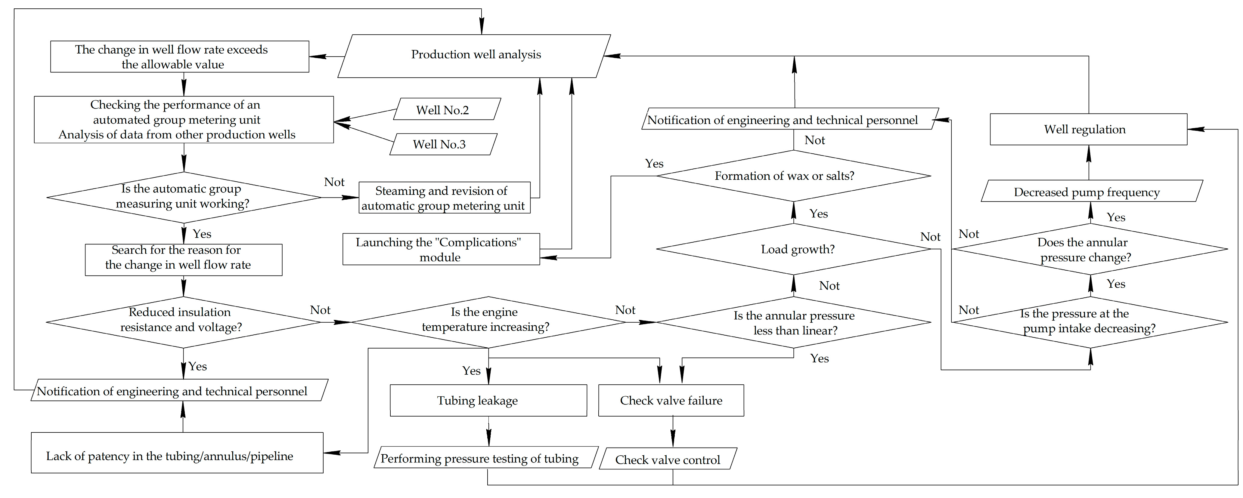
An example of an algorithm for identifying the cause of a debit deviation is shown in Figure 4.
According to the algorithm, the system can automatically eliminate some of the causes of deviations, which it can check automatically. The system analyzes well flow rates and equipment operation parameters. The initial action is to check the operability of the automatic group metering plant as a source of metering data. So, with a simultaneous increase or decrease in the flow rate for all production wells without a significant change in the parameters of the downhole pumping equipment, the most likely cause may be a malfunction of the automatic group metering unit (waxing of measuring instruments). Then, the parameters of the well operation are analyzed and possible violations are determined, among them are: leakage of the pipe, lack of patency in the pipe or flow line, check valve malfunction, clogging of the working parts of the pump or inlet filter, clogging of the nozzle, decrease in bottomhole pressure and others. According to the above algorithm, the ACS evaluates which deviation is most likely in the current conditions. After determining the list of possible reasons for the deviation, the system downloads a list of solutions to problems from the database and offers them to the operator or sends a control signal, depending on the operating mode.
The operation of the module allows you to determine the cause of the well flow rate deviation and quickly correct it. So, if all the wells on the cluster experience a decrease in flow rate, the system will automatically offer to revise the metering unit.
3.4. Module “Prediction of Deviations in Equipment Operation”
This module is aimed at reducing downtime of process equipment by minimizing emergency shutdowns of the SEM through high-quality prediction and automatic response to possible deviations in the well or surface equipment.
This module is based on machine learning. ACS is pre-trained on the basis of a large array of actual data on the operation of equipment in which an emergency condition or a critical state of equipment operation has developed [44,45]. To train the model, XGBoost is used, a machine learning algorithm based on a decision search tree and using the gradient boosting framework [46,47]. Decision trees are used as basic learners, and at each iteration, the calculated error is used to correct the previous predictor (trainee), while the change in model performance is evaluated using the objective function. For example, pre-training is performed to identify the development of deviations in conditions of clogging of the working bodies with a mixture of mechanical impurities and paraffin deposits, an increase in gas content at the ESP intake, circulation of well products through a leaky valve or pipe, a decrease in bottomhole pressure, fatigue wear of pumping equipment and other conditions. According to the result of training, the ACS notifies in advance about the beginning of the development of a complication and issues recommendations or a control signal for its preventive elimination.
As a result of the application of the module, it is possible to predict deviations in the operation of the equipment, based on the history of operation. Thus, when training the system, it is able to assess the degree of degradation of the ESP and to suggest how many days of operation the degradation will lead to an emergency. This will allow you to make the most of the history of the wells.
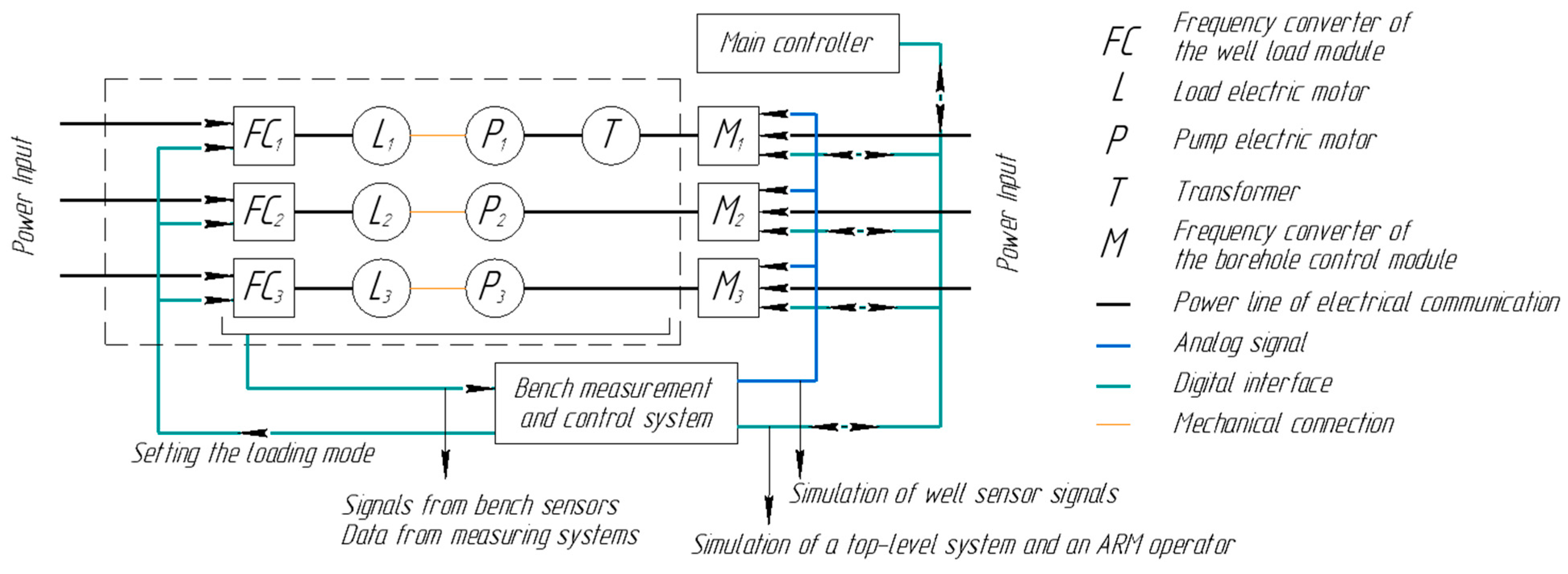
3.5. Testing Stand
To test the operation of the system, a WCS layout was created, the scheme of which is shown in Figure 5.
The essence of the work of the stand is to set the load mode on the load motors, the shafts of which are connected by a coupling connection with the motors representing the pump motors. The operation of this system allows simulating the operation of an oil well according to the solutions presented in [48,49,50]. Information signals about the operation of the oil production station are sent to the well cluster control station model. If it is necessary to simulate changes in operating parameters, a signal is sent to the load motors to the rotation resistance of the main motor shaft. The remaining parameters of the stand operation are fed into the system in the form of information signals. The result of the work is the ability to monitor the reaction of the system to a change in a particular parameter of the well operation. The C Sharp programming language was used to write the control module model, and the Math.Net package was used to perform numerical calculations.
As part of testing the operation of optimization algorithms (see Section 2.1) for 10 wells, optimization of electricity consumption was carried out by selecting the optimal frequency of the pump or installing a choke The testing algorithm was as follows: data on the operation of a real oil well was fed to the ACS. It is worth noting that the deviation of the calculated energy consumption of the well deviates from the actual one by less than 3%, which confirms the correctness of the algorithms laid down. Then, ACS offered options for optimizing the operation of the well. For each algorithm, based on mathematical modeling, the energy consumption of the well was estimated and a conclusion was made about the possibility of reducing electricity consumption. As a result, for all wells, it was possible to achieve a reduction in electricity consumption by up to 10% (Table 1).
4. Discussion
A modern digital automated system for managing and optimizing the operation of the fund of oil-producing wells has been developed. The automated control system is a comprehensive software product that provides the functions of continuous monitoring and control of the parameters of the operation of an oil well and auxiliary technological equipment. Algorithms for optimizing energy consumption, presented in Section 2.1.3, ensuring the flow rate of wells within the reservoir potential and deep-pumping equipment are being implemented. The development of deviations in the operation of the equipment is predicted and the causes of the event are eliminated through the use on machine learning. The work of all the developed modules consists in analyzing the parameters of the well operation, numerical modeling of production processes, determining the optimal operating mode and bringing the parameters of the well operation to the optimal mode.
Considering the developed ACS in the context of the current state of oil production, several important observations can be made. The ACS software part is designed so that its operation is possible on various models of technological processes. As a result, the authors can argue that the process of adapting ACS operation to various configurations of technological equipment is not a problem during operation, but depends only on the user’s ability to describe technological processes. The main purpose of ACS is to assist in decision–making by continuously monitoring the parameters of the well operation, automatically identifying the causes of equipment failure and providing this analysis to engineering and technical personnel. Due to the acceleration of decision-making, a reduction in the cost of emergency stops and repairs of equipment is achieved. The presented ACS has the ability to work in the modes “Advisor” and automatic mode. In the “Advisor” mode, the ACS only issues advisory messages, and in the “automatic” mode, it can independently choose one or another way to solve a problem when it occurs. The advantage of the “Advisor” mode is the confirmation of all actions by a specialist, and the automatic mode—the ability to continuously optimize the work of the well, regardless of the state, experience and presence of the system operator.
The automated control system makes it possible to improve the quality and speed of decision-making in the event of deviations in the operation of pumping equipment operated in complicated conditions. The implemented functions make it possible to eliminate the causes of deviations in automatic mode, which helps to reduce the labor costs of engineering and technological personnel for collecting and analyzing information. The human factor in the decision-making process is minimized. Reduction of specific energy consumption during pumping operation of producing wells by up to 10% is provided.
The disadvantages of the presented system are the metal and science intensity of production, the need for verification and development of many methods for effective application. It is also worth noting that the centralization of control processes increases the risk of failure (for example, in case of power failure), which must also be considered.
5. Conclusions
This article proposes a solution to the problem of automatic control of oilfield equipment used in downhole oil production. The introduction of a digital system for managing the production well stock is aimed at solving the following strategic tasks:
- Optimization of operating parameters of the extractive fund;
- Increasing the competitiveness of oil and gas companies in the international market of the fuel and energy complex;
- Creation of a unified information and analytical space within the oil field, taking into account data on the operation of all equipment when making decisions.
- Improving the applied digital products for the oil and gas industry;
- Intellectualization of digital twins of production processes in the field of hydrocarbon production.
Future Research
The direction of research implemented by the scientific team corresponds to the strategy of digital transformation of the oil industry. At present, a program and methodology for testing a digital automated system for controlling and optimizing the work of the well stock has been developed. At the next stage, research tests of the automated control system will be carried out using a stand that reproduces the actual operating conditions of oilfield equipment, including a well cluster and peripheral equipment.
Further studies may include studying the possibility of mathematical modeling of well interaction within the reservoir pressure distribution, the economic evaluation of the use of one control station for a large number of wells, and the economic effect of taking into account the interaction.
Author Contributions
Conceptualization, I.P.Y., V.K.A. and K.A.V.; methodology, K.A.V.; software, V.K.A.; validation, V.K.A. and K.A.V.; formal analysis, I.P.Y.; resources, I.P.Y.; data curation, I.P.Y.; writing—original draft preparation, K.A.V.; writing—review and editing, I.P.Y. and V.K.A.; visualization, K.A.V.; supervision, I.P.Y.; project administration, I.P.Y.; funding acquisition, I.P.Y. All authors have read and agreed to the published version of the manuscript.
Funding
The work was carried out in the organization of the Lead Contractor as part of the R&D, with the financial support from the Ministry of Science and Higher Education of the Russian Federation (agreement number 075-11-2021-052 of 24 June 2021) in accordance with the decree of the Government of the Russian Federation: 09.04.2010, number 218 (PROJECT 218). The main R&D contractor is the Perm National Research Polytechnic University.
Data Availability Statement
Not applicable.
Conflicts of Interest
The authors declare no conflict of interest.
References
- Doroshenko, V.; Titlov, A. Analysis of the directions for improving the development systems for oil fields at the later stage. Technol. Audit. Prod. Reserves 2021, 1, 57. [Google Scholar]
- Diehl, F.C.; Machado, T.O.; Anzai, T.K.; Almeida, C.S.; Moreira, C.A.; Nery, G.A., Jr.; Campos, M.C.; Farenzena, M.; Trierweiler, J.O. 10% increase in oil production through a field applied APC in a Petrobras ultra-deepwater well. Control. Eng. Pract. 2019, 91, 104108. [Google Scholar] [CrossRef]
- Ilyushin, P.Y.; Vyatkin, K.A.; Kozlov, A.V. Investigating the influence of production string diameter of oil well on paraffin deposition intensity. Oil Industy 2022, 1183, 98–102. [Google Scholar] [CrossRef]
- Midor, K.; Ivanova, T.N.; Molenda, M.; Biały, W.; Zakharov, O.V. Aspects of energy saving of oil-producing enterprises. Energies 2021, 15, 259. [Google Scholar] [CrossRef]
- Krishnamoorthy, D.; Fjalestad, K.; Skogestad, S. Optimal operation of oil and gas production using simple feedback control structures. Control. Eng. Pract. 2019, 91, 104107. [Google Scholar] [CrossRef]
- Bukreev, V.; Sipaylova, N.; Control, V.S. strategy in accordance with economical criterion for electrotechnical installation of mechanized oil production. Bull. Tomsk. Polytech. Univ. Geo Assets Eng. 2017, 328, 75–84. [Google Scholar]
- Ulyasheva, V.M.; Ponomarev, N.S.; Martianova, A.Y. Analysis of energy consumption of remote objects of an oil field. Bull. Civ. Eng. 2020, 1, 162–167. [Google Scholar]
- Ilushin, P.Y.; Vyatkin, K.A.; Kozlov, A.V. Development of intelligent algorithms for controlling peripheral technological equipment of the well cluster using a single control station. Bull. Tomsk. Polytech. Univ. Geo Assets Eng. 2022, 333, 59–68. [Google Scholar]
- Zyuzev, A.M.; Bubnov, M.V. Sucker-rod pumping unit balance diagnostics by wattmeter card. Bull. Tomsk. Polytech. Univ. Geo Assets Eng. 2019, 330, 178–187. [Google Scholar]
- Foss, B. Process control in conventional oil and gas fields—Challenges and opportunities. Control Eng. Pract. 2012, 20, 1058–1064. [Google Scholar] [CrossRef]
- Zheng, X.; Shi, J.; Cao, G.; Yang, N.; Cui, M.; Jia, D.; Liu, H. Progress and prospects of oil and gas production engineering technology in China. Pet. Explor. Dev. 2022, 49, 644–659. [Google Scholar] [CrossRef]
- Lu, H.; Guo, L.; Azimi, M.; Huang, K. Oil and Gas 4.0 era: A systematic review and outlook. Comput. Ind. 2019, 111, 68–90. [Google Scholar] [CrossRef]
- Shigina, A.A.; Antipina, S.M.; Stupina, A.A.; Tynchenko, V.S.; Dzhioeva, N.N. Procedure of Analysis and Digital Processing of Large Data Array in Real Time upon Intellectualization of Roller Drilling. Int. J. 2020, 8, 2812–2823. [Google Scholar]
- Zahirović, I.; Danilović, D.; Martinović, B. Application of ESP pump with intelligent control system in well X. Podzemn. Rad. 2020, 37, 51–59. [Google Scholar] [CrossRef]
- Tagirova, K.F. Architecture of an intelligent automated control system of an oil production pumping unit. High Perform. Comput. 2018, 2, 124–129. [Google Scholar]
- Kuang, L.; Liu, H.; Ren, Y.; Luo, K.; Shi, M.; Su, J.; Li, X. Application and development trend of artificial intelligence in petroleum exploration and development. Pet. Explor. Dev. 2021, 48, 1–14. [Google Scholar] [CrossRef]
- Wan, J.; Li, J.; Hua, Q.; Celesti, A.; Wang, Z. Intelligent equipment design assisted by Cognitive Internet of Things and industrial big data. Neural Comput. Appl. 2020, 32, 4463–4472. [Google Scholar] [CrossRef]
- Krishnamoorthy, D.; Bergheim, E.M.; Pavlov, A.; Fredriksen, M.; Fjalestad, K. Modelling and robustness analysis of model predictive control for electrical submersible pump lifted heavy oil wells. IFAC Pap. 2016, 49, 544–549. [Google Scholar] [CrossRef]
- Garifullin, A.R.; Slivka, P.I.; Gabdulov, R.R.; Davletbaev, R.V.; Baiburin, B.K.; Kliushin, I.G. “Smart wells”—System of automated control over oil and gas production. Oil Gas Innov. 2017, 12, 24–32. [Google Scholar]
- Zubairov, I.F. Intelligent well–improving the efficiency of mechanized production. Autom. Telemech. Commun. Oil Ind. 2013, 13, 25–32. [Google Scholar]
- Kramarenko, V.A.; Lunev, A.S.; Kaizer, Y.F.; Tyukanov, V.L.; Lysyannikov, A.V.; Kuznetsov, A.V.; Chavyraa, C.D.; Sharshembiev, J.S. Automation of management and control system for well wellhead equipment of a production. In Journal of Physics: Conference Series; IOP Publishing: Bristol, UK, 2020; Volume 1515, p. 042085. [Google Scholar]
- Tagirova, C.; Gladkih, A.; Bakiev, D.; Vulfin, A. Modular structure of the intelligent oil production equipment control station. In Proceedings of the 2020 2nd International Conference on Control Systems, Mathematical Modeling, Automation and Energy Efficiency (SUMMA), Lipetsk, Russia, 11–13 November 2020; IEEE: New York, NY, USA, 2020; pp. 539–544. [Google Scholar]
- Chacón, E.; Besembel, I.; Hennet, J.C. Coordination and optimization in oil and gas production complexes. Comput. Ind. 2004, 53, 17–37. [Google Scholar] [CrossRef]
- Kulaev, E.G.; Eliseev, D.B.; Vetokhin, E.G. Results of application of control stations of ESP with an intelligent system in JSC “Samotlorneftegaz”. Equip. Technol. Oil Gas Complex 2013, 6, 19–25. [Google Scholar]
- Iranzi, J.; Son, H.; Lee, Y.; Wang, J. A Nodal Analysis Based Monitoring of an Electric Submersible Pump Operation in Multiphase Flow. Appl. Sci. 2022, 12, 2825. [Google Scholar] [CrossRef]
- Odjugo, T.; Baba, Y.; Aliyu, A.; Okereke, N.; Oloyede, L.; Onifade, O. Optimisation of Artificial Lifts Using Prosper Nodal Analysis for BARBRA-1 Well in Niger Delta. Niger. J. Technol. Dev. 2020, 17, 150–155. [Google Scholar] [CrossRef]
- Brill, J.P.; Mukherjee, H. Multiphase Flow in Wells; Society of Petroleum Engineers Inc.: Richardson, TX, USA, 1999; p. 164. [Google Scholar]
- Vogel, J.V. Inflow performance relationships for solution-gas drive wells. J. Pet. Technol. 1968, 20, 83–92. [Google Scholar] [CrossRef]
- Adeyemi, T.S.; Rufus, D. Analytical Development of an Improved Inflow Performance Relationship (IPR) Model for Solution Gas Drive Reservoirs. J. Hum. Earth Future 2021, 2, 125–135. [Google Scholar] [CrossRef]
- Hagedorn, A.R.; Brown, K. Experimental study of pressure gradients occurring during continuous two-phase flow in small-diameter vertical conduits. J. Pet. Technol. 1965, 17, 475–484. [Google Scholar] [CrossRef]
- Cox, S.A. Errors Introduced by Multiphase Flow Correlations on Production Analysis. In SPE Annual Technical Conference; OnePetro: San Antonio, TX, USA, 2006. [Google Scholar]
- Guo, B.; Lyons, W.; Ghalambor, A. Petroleum Production Engineering. A Computer-Assisted Approach; Gulf Professional Publishing: Houston, TX, USA, 2007; p. 287. [Google Scholar]
- Takacs, G. Electrical Submersible Pumps Manual: Design, Operations, and Maintenance; Gulf Professional Publishing: Houston, TX, USA, 2009; p. 440. [Google Scholar]
- Lyakhomskii, A.; Petrochenkov, A.; Romodin, A.; Perfil’eva, E.; Mishurinskikh, S.; Kokorev, A.; Kokorev, A.; Zuev, S. Assessment of the Harmonics Influence on the Power Consumption of an Electric Submersible Pump Installation. Energies 2022, 15, 2409. [Google Scholar] [CrossRef]
- Ivanovskiy, V.N.; Darishchev, V.I.; Sabirov, A.A.; Kashtanov, V.S.; Pekin, S.S. Borehole Pumping Units for Oil Production; Oil and Gas Publishing: Moscow, Russia, 2002; p. 824. [Google Scholar]
- Petrochenkov, A.; Ilyushin, P.; Mishurinskikh, S.; Kozlov, A. Development of a Method for Improving the Energy Efficiency of Oil Production with an Electrical Submersible Pump. Inventions 2023, 8, 29. [Google Scholar] [CrossRef]
- Ilyushin, P.Y.; Vyatkin, K.A.; Kozlov, A.V. Investigation of rheological properties of oil during the formation of wax deposits. Results Eng. 2022, 14, 100434. [Google Scholar] [CrossRef]
- Sousa, A.L.; Matos, H.A.; Guerreiro, L.P. Preventing and removing wax deposition inside vertical wells: A review. J. Pet. Explor. Prod. Technol. 2019, 9, 2091–2107. [Google Scholar] [CrossRef]
- Ahmadi, M. Data-driven approaches for predicting wax deposition. Energy 2023, 265, 126296. [Google Scholar] [CrossRef]
- Wang, W.; Huang, Q.; Li, S.; Wang, C.; Wang, X. Identifying optimal pigging frequency for oil pipelines subject to non-uniform wax deposition distribution. In Proceedings of the International Pipeline Conference, Calgary, AB, Canada, 29 September–3 October 2014; American Society of Mechanical Engineers: New York, NY, USA, 2014; Volume 46131, p. V004T08A004. [Google Scholar]
- Tian, H.; Deng, S.; Wang, C.; Ni, X.; Wang, H.; Liu, Y.; Ma, M.; Wei, Y.; Li, X. A novel method for prediction of paraffin deposit in sucker rod pumping system based on CNN indicator diagram feature deep learning. J. Pet. Sci. Eng. 2021, 206, 108986. [Google Scholar] [CrossRef]
- Raya, S.A.; Saaid, I.M.; Ahmed, A.A.; Umar, A.A. A critical review of development and demulsification mechanisms of crude oil emulsion in the petroleum industry. J. Pet. Explor. Prod. Technol. 2020, 10, 1711–1728. [Google Scholar] [CrossRef] [Green Version]
- Zhu, J.; Zhang, H.Q. A review of experiments and modeling of gas-liquid flow in electrical submersible pumps. Energies 2018, 11, 180. [Google Scholar] [CrossRef] [Green Version]
- Bikmukhametov, T.; Jäschke, J. First principles and machine learning virtual flow metering: A literature review. J. Pet. Sci. Eng. 2020, 184, 106487. [Google Scholar] [CrossRef]
- Ragab, A.; Ghezzaz, H.; Amazouz, M. Decision fusion for reliable fault classification in energy-intensive process industries. Comput. Ind. 2022, 138, 103640. [Google Scholar] [CrossRef]
- Asselman, A.; Khaldi, M.; Aammou, S. Enhancing the prediction of student performance based on the machine learning XGBoost algorithm. Interact. Learn. Environ. 2021, 1–20. [Google Scholar] [CrossRef]
- Li, Z. Extracting spatial effects from machine learning model using local interpretation method: An example of SHAP and XGBoost. Comput. Environ. Urban Syst. 2022, 96, 101845. [Google Scholar] [CrossRef]
- Pavlov, N.V.; Petrochenkov, A.B.; Romodin, A.V. A Multiagent Approach for Modeling Power-Supply Systems with MicroGrid. Russ. Electr. Eng. 2021, 92, 637–643. [Google Scholar] [CrossRef]
- Petrochenkov, A.; Romodin, A.; Kazantsev, V.; Sal’Nikov, A.; Bochkarev, S.; Gagarin, Y.; Shapranov, R.; Brusnitcin, P. Principles of Imitation for the Loading of the Test Bench for Gas Turbines of Gas Pumping Units, Adequate to Real Conditions. Sustainability 2021, 13, 13678. [Google Scholar] [CrossRef]
- Inozemtsev, A.; Petrochenkov, A.; Kazantsev, V.; Shmidt, I.; Sazhenkov, A.; Dadenkov, D.; Gribkov, I.; Ivanov, P. The fuzzy logic in the problems of test control of a bypass turbojet engine gas generator. Mathematics 2022, 10, 484. [Google Scholar] [CrossRef]
Figure 1.
Distribution of the mining fund by the method of operation.

Figure 2.
Automated well cluster control system.

Figure 3.
Scheme of operation of the “Complications” module of the automated well cluster control system.
Figure 3.
Scheme of operation of the “Complications” module of the automated well cluster control system.

Figure 4.
Algorithm for analyzing the cause of well flow rate deviation.

Figure 5.
Stand for testing a well cluster control station.


Table 1.
Test results.
| Well № | Well Operation Mode | Daily Energy Consumption before Optimization, kWa | Daily Energy Consumption after Optimization, kWa | Decrease in Consumption, % |
|---|---|---|---|---|
| 1 | Periodic | 128 | 117 | 9.4 |
| 2 | Constant | 850 | 840 | 1.2 |
| 3 | Constant | 488 | 468 | 4.3 |
| 4 | Constant | 1165 | 1135 | 2.6 |
| 5 | Periodic | 126 | 116 | 8.4 |
| 6 | Periodic | 333 | 317 | 5.0 |
| 7 | Constant | 458 | 423 | 8.3 |
| 8 | Constant | 611 | 556 | 10.0 |
| 9 | Constant | 576 | 538 | 7.1 |
| 10 | Constant | 1343 | 1339 | 0.3 |
Disclaimer/Publisher’s Note: The statements, opinions and data contained in all publications are solely those of the individual author(s) and contributor(s) and not of MDPI and/or the editor(s). MDPI and/or the editor(s) disclaim responsibility for any injury to people or property resulting from any ideas, methods, instructions or products referred to in the content. |
© 2023 by the authors. Licensee MDPI, Basel, Switzerland. This article is an open access article distributed under the terms and conditions of the Creative Commons Attribution (CC BY) license (https://creativecommons.org/licenses/by/4.0/).
Share and Cite
MDPI and ACS Style
Pavel Yurievich, I.; Kirill Andreevich, V.; Anton Vadimovich, K. Development of a Digital Well Management System. Appl. Syst. Innov. 2023, 6, 31. https://doi.org/10.3390/asi6010031
AMA Style
Pavel Yurievich I, Kirill Andreevich V, Anton Vadimovich K. Development of a Digital Well Management System. Applied System Innovation. 2023; 6(1):31. https://doi.org/10.3390/asi6010031
Chicago/Turabian StylePavel Yurievich, Ilyushin, Vyatkin Kirill Andreevich, and Kozlov Anton Vadimovich. 2023. "Development of a Digital Well Management System" Applied System Innovation 6, no. 1: 31. https://doi.org/10.3390/asi6010031