Article

Nonlinear Dynamics of a Resonant-Impact Dielectric Elastomer Actuator

1
Research Centre for Medical Robotics and Minimally Invasive Surgical Devices, Shenzhen Institute of Advanced Technology (SIAT), Chinese Academy of Sciences, Shenzhen 518055, China
2
School of Mechanical and Electrical Engineering, Xi’an University of Architecture and Technology, Xi’an 710055, China
*
Author to whom correspondence should be addressed.
Appl. Syst. Innov. 2022, 5(6), 122; https://doi.org/10.3390/asi5060122
Submission received: 15 November 2022 / Revised: 28 November 2022 / Accepted: 2 December 2022 / Published: 5 December 2022
(This article belongs to the Special Issue Smart Soft Robotics: Design, Control and Applications)

Abstract

:
In recent years, with the rapid development of soft robots, dielectric elastomer actuators (DEAs) as a novel type of soft actuators have been widely studied. However, DEAs often suffer from low instantaneous output force/power, especially in high payload damping conditions, which limits their applications in certain scenarios. Inspired by the vibro-impact mechanisms found in many engineering systems (e.g., pile driving and percussive drilling), a resonant-impact DEA system was proposed in the authors’ previous work to potentially address this limitation. However, due to the complex nonlinearities and unique electromechanically coupled forcing mechanism of DEAs, no nonlinear dynamic model was developed to perform systematic investigations and optimization. In this paper, a nonlinear dynamic model of the resonant-impact DEA system is developed by considering multiple nonlinearities, viscoelasticity, and electromechanical coupling. Using both a numerical model and extensive experiments, the nonlinear dynamics of the resonant-impact DEA system are studied in depth. The effects of several key parameters, including excitation voltage amplitude, constraint gap, constraint stiffness, and number of DEA layers, on the dynamic response of the system are characterized. The findings reported in this paper can provide guidance for the performance optimization of resonance-impact DEA systems and their applications.

1. Introduction

Conventional industrial rigid robots have been successfully adopted for various automatic assembling and manufacturing tasks [1,2,3]. However, with the expansion of robotics from manufacturing automation to health care, environmental exploration, and other fields, soft robots that have excellent adaptability to dynamic environments thanks to their inherent deformation are becoming a major research focus [4,5,6]. Different from conventional rigid actuators, the soft actuation technology used in soft robots mainly relies on the stimulation responses of soft materials to exert actuation motions; as such, it can potentially adapt better to various environments and achieve safer human–robot interactions.
Dielectric elastomer actuators (DEAs) are an emerging type of novel soft actuators that can respond to electrical stimulations [7]. DEAs have the advantages of large actuation strains and high energy densities and efficiencies [8,9,10], and have broad application prospects in soft robotic locomotion [11,12,13], soft grippers [14,15], and wearable devices [16,17]. Along with these advantages, DEAs can utilize their inherent elasticity to achieve resonant actuation, which can greatly increase the number of strokes, hence boosting their outputs and energy efficiencies. For instance, Tang et al. [18] developed a DEA-driven pipeline inspection robot which can fit into pipes with sub-centimeter diameters and various curvatures while achieving rapid motions horizontally (1.19 body-length (BL)/s) and vertically (1.08 BL/s) in a pipe. Cao et al. [19] reported a diaphragm pump driven by a magnetically coupled dielectric elastomer actuator (MCDEA) at its resonance, which shows a maximum output pressure of 30.5 mbar and a flow rate of 0.9 L/min. Gu et al. [20] presented a DEA and electroadhesive feet-driven tethered soft wall-climbing robot, which was able to reach a velocity of up to 0.75 BL/s and climb walls made of wood, paper, and glass. Chen et al. [21] proposed an aerial robot driven by multi-layered resonant DEAs which demonstrates open-loop and passively stable ascending flight as well as closed-loop hovering flight. It is noteworthy that the DEAs discussed in the literature all drive their payloads (e.g., viscous fluids) directly. However, it has been demonstrated [9,22] that high payload damping (e.g., high frictions or viscosities) can significantly affect the resonant strokes of DEAs, thereby reducing both their average and instantaneous output force/power and efficiency. This greatly limits their potential application in certain scenarios, such as soft robotic locomotion in granular, collapsed, or mucosal media.
Vibro-impact is a widely adopted mechanism in engineering, and can potentially solve the aforementioned limitations in DEAs. A vibro-impact system utilizes an actuator to drive an internal mass to realize periodic oscillation; the internal mass impacts with the constraint in each cycle, and the impact force is transferred by the constraint to the payload as the output [23]. As the vibro-impact mechanism mainly rely on a large instantaneous force during impact as the output, rather than driving the payload by the actuator directly, the damping in the payload shows negligible effects on the oscillation of the internal mass and the output performance of the system. Vibro-impact mechanisms have been adopted in various engineering applications, such as vibro-impact drilling [24,25,26], energy harvesting [27,28,29], and pipeline robots [30,31]. Li et al. [32] studied a harmonic vibro-impact drilling system and modelled the energy response of rock under harmonic vibro-impact. A position feedback control strategy for modelling vibro-impact drilling was presented by Liu et al. [33]. Moss et al. [34] proposed a broadband kinetic energy harvester based on a vibro-impact oscillator. Guo et al. [35] reported a self-contained vibro-impact wave energy converter with enhanced performance. In a different study, Guo et al. [36] proposed a vibro-impact self-propulsion capsule endoscope for small-bowel examination, which was able to achieve a forward velocity of 8.49 mm/s. However, it is worth noting that existing vibro-impact systems mainly rely on rigid actuators such as servomotors or solenoid coils to generate impact forces. These rigid and bulky actuators severely limit the adaptability of robotic systems in unstructured environments, and may raise potential risks during human–robot interactions.
Therefore, utilizing a vibro-impact mechanism and a DEA, we proposed a soft actuator-based resonant-impact DEA system in our previous study [37]. This system mainly consists of a resonant DEA and an elastic constraint as the output to any payloads. This design separates the resonant DEA from the payloads, thus minimizing the negative effects of high payload damping on its resonant strokes. Meanwhile, the elastic constraint transfers the impact force to the payload effectively. The resonant-impact DEA system combines the advantages of the high instantaneous force/power output of a vibro-impact mechanism and the high energy efficiency and stroke of a resonant DEA. A novel crawling robot was developed based on this mechanism, and its crawling locomotion was demonstrated on various surfaces with different friction coefficients. However, the previous work was limited solely to experimental analyses. Despite nonlinear dynamic responses being characterized briefly in our experiments, no model of the resonant-impact DEA system is available to perform in-depth theoretical investigations or optimization due to the multiple nonlinearities and unique electromechanically coupled forcing mechanism of the DEAs.
In this paper, we first develop a nonlinear dynamic model by considering the structural, material, and constraint nonlinearities and electromechanical coupling of the DEA. Utilizing the developed model, we investigate the nonlinear dynamics of the resonant-impact DEA system in depth through extensive experiments. This paper characterizes the effects of key parameters such as the excitation voltage amplitude, constraint gap, constraint stiffness, and the number of DEA layers on the dynamic responses of the system. The study of the nonlinear dynamics of the resonant-impact DEA system provides guidance for the design and performance optimization of systems and their applications.
The rest of this paper is organized as follows. Section 2 introduces the design, working principle, and numerical model of the resonant-impact DEA system. Our comparative analyses of the numerical and experimental results of different design parameters are characterized in Section 3. Finally, our conclusions are presented in Section 4.

2. Methods

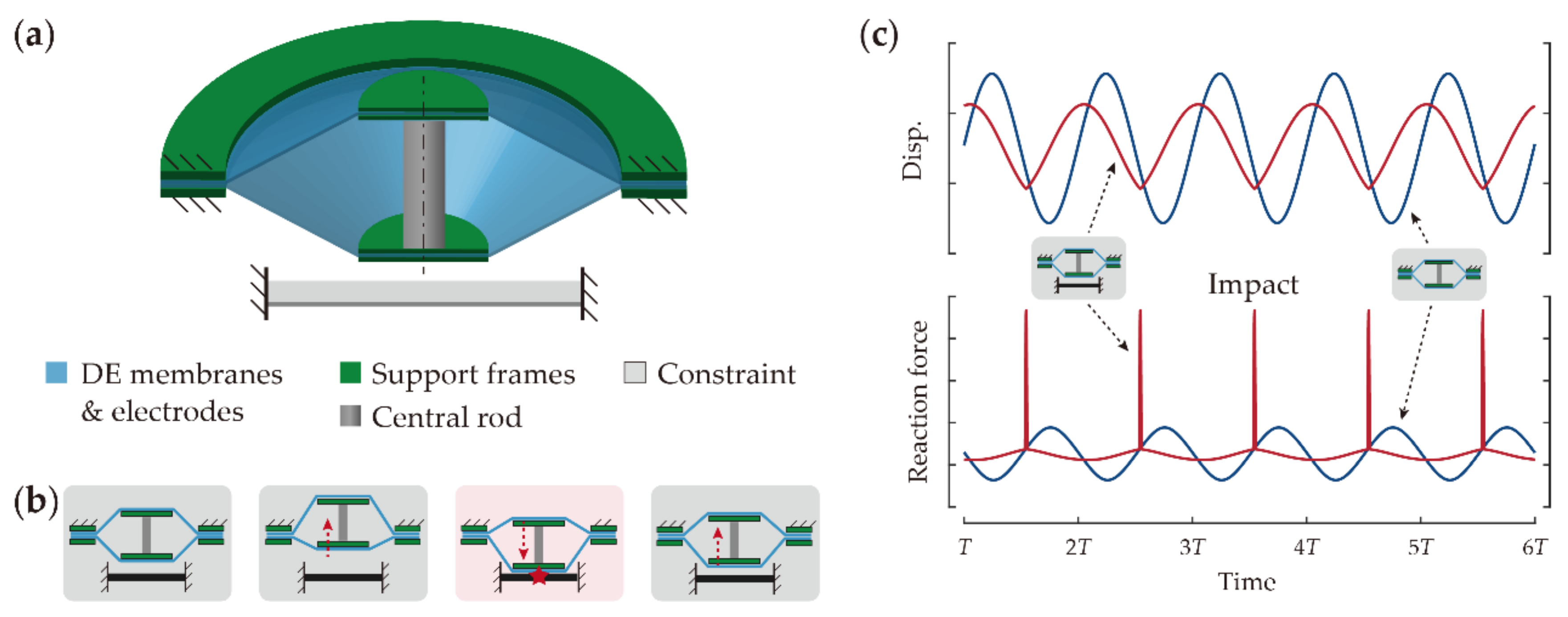
2.1. Design Overview and Working Principle

The resonant-impact DEA system studied in this work mainly consists of a double cone DEA and a constraint, as illustrated in Figure 1a. The double cone configuration is adopted as the driving unit due to its ease of fabrication and large stroke/force output [38,39,40]. It consists of two identical circular DE membranes connected by a rigid rod in the center and support rings in the outer ends, which deform the two membranes to symmetrical conical shapes. An elastic constraint is fixed to one side with a gap to complete the resonant-impact DEA system. In this design, the gap is set to be higher than the quasi-static stroke of the DEA, i.e., no impact occurs when the excitation frequency Ωe significantly differs from the resonant frequency of the DEA unit Ωr. When anti-phase voltages are respectively applied to the two DE membranes at an excitation frequency close to Ωr, the oscillation amplitude of the moving mass (including the central rod and disks) increases to be greater than the gap, which realizes periodic impacts of the system. The motion of the resonant-impact DEA system in one typical impact oscillation cycle is illustrated in Figure 1b. It can be noted that the moving mass first departs from the constraint, which results in an increase in the elastic potential energy in the system due to the stretched membranes. When the moving mass passes its top dead-end, the stored elastic potential energy is released and converted to the kinetic energy of the moving mass. When impact occurs, the kinetic energy drops sharply and a part the energy is transferred to the constraint as the output.
Figure 1c compares the displacements and reaction forces on the rig (which can be considered as the force output) of the proposed resonant-impact DEA and an identical DEA counterpart without the impact constraint. It can be noted that, despite the smaller displacement amplitude near resonance, the proposed resonant-impact DEA can exert a substantially higher peak output force than its counterpart without the impact constraint.

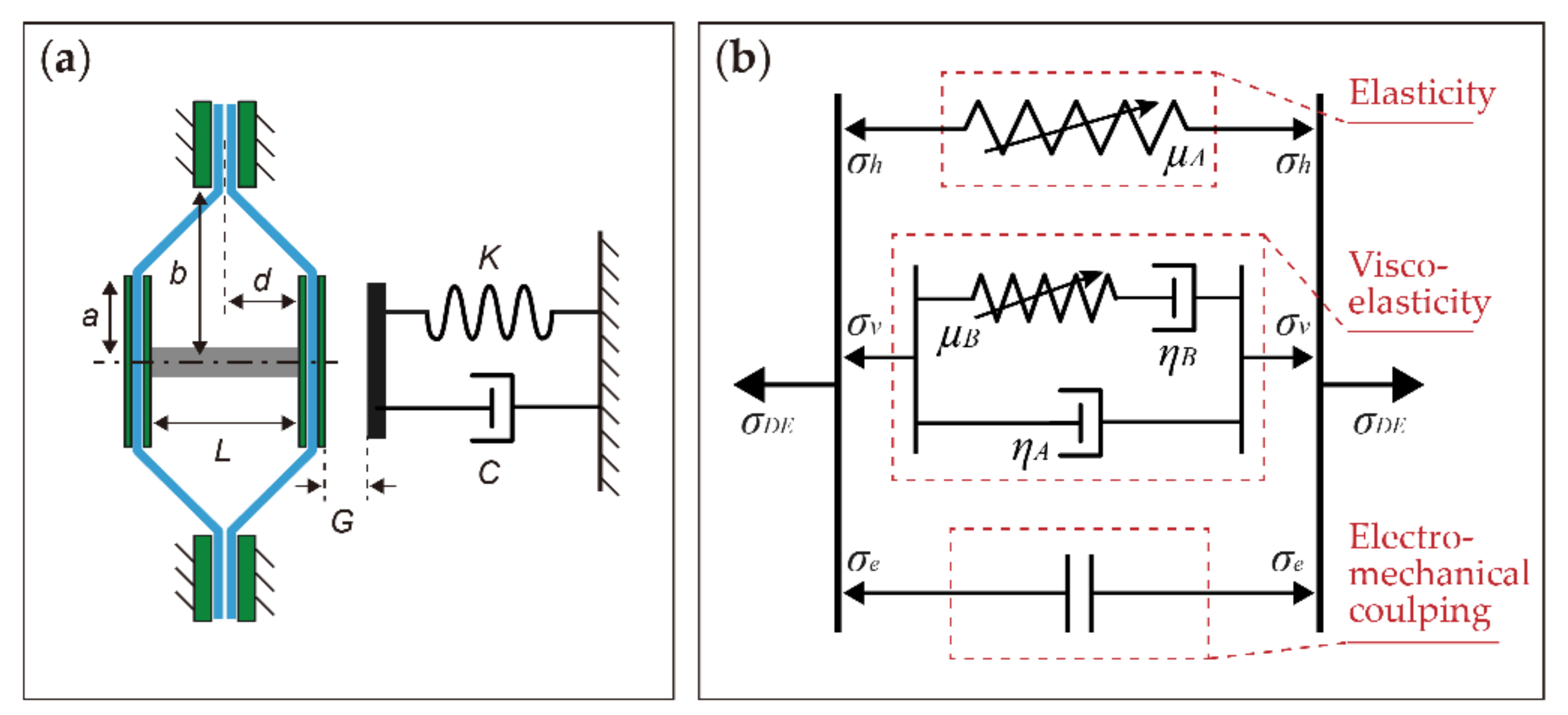
2.2. Numerical Model

2.2.1. Equation of Motion Development

To investigate the nonlinear dynamics of the resonant-impact DEA system, it is necessary to first develop a dynamic model of it. A sketch of the system is illustrated in Figure 2a; it can be noted that the system model mainly includes the nonlinear dynamic model of the DEA unit and its interaction with the elastic constraint. To avoid overcomplication of the system model, the following simplifying assumptions are made here: (i) the DEA unit is single degree-of-freedom, i.e., only its translation along the cylindrical axis is analyzed; (ii) the deformations of the DEA membranes are truncated conical deformations; (iii) the strain distributions on the DEA membranes are homogeneous; (iv) the circumferential deformations of the DEA membranes remain constant; (v) the electrical response time of the DEA unit is negligible; (vi) the constraint is massless, i.e., the system is single degree-of-freedom.
The equation of motion of the moving mass is
m d ¨ + F c o n t a c t + F D E _ I F D E _ I I = 0
where m is the total moving mass, d is the out-of-plane deformation of DE unit I (close to the constraint), Fcontact is the force exerted by the constraint, and FDE_I and FDE_II are the force exerted by DE units I and II, respectively.
The contact force of the constraint is provided by the following equation:
F c o n t a c t = 0 ,   d L / 2   <   G K   d L / 2 G c d ˙ ,   d L / 2   G
where G is the gap distance, L is the rod length, K is the stiffness of the constraint, and c is its damping coefficient.
The force exerted by the membrane along the cylindrical axis FDE_i can be written as
F D E _ i = 2 π a T 0 λ 1 _ i λ 2 _ i σ D E _ i s i n θ _ i
where i = I and II for DE units I and II, respectively, a is the radius of the central disk, T0 is the initial thickness of the membrane, λ1 and λ2 are the radial and circumferential stretch of the membrane, respectively, σDE is the radial stress of the membrane (and is developed further below), and θ is the out-of-plane deformation angle of the membrane.
To characterize the strain–stress relationship of the dielectric elastomer, the hyperelasticity, viscoelasticity, and electromechanical coupling are taken into account, as illustrated in Figure 2b. A first-order Ogden model is adopted to describe the hyperelastic characteristic [41], and a rheological model with parallel Kelvin–Voigt and Maxwell models is utilized to account for viscoelasticity [42]. The total radial stress of the membrane when subjected to a stretch and a voltage can be written as
σ D E = σ h + σ v + σ e
where σh is the hyperelastic stress, σv is the viscoelastic stress, and σe is the electrostatic stress.
The hyperelastic stress is described by a first-order Ogden model [41]:
σ h = μ A λ 1 α A λ 1 α A λ 2 α A
where μA is the shear modulus of the spring in the first branch of this material model and αA is a power constant.
The viscoelasticity of the dielectric elastomer is characterized by a rheological model with parallel Kelvin–Voigt and Maxwell models [42], and is provided as follows:
σ v = μ B λ 1 e α B λ 1 e α B λ 2 e α B + η A d λ 1 d t
where μB is the shear modulus of the spring in the third branch of this material model, αB is a power constant, λ 1 e = λ 1 / ξ 1 is the stretch of the spring on the second branch in the rheological model, ξ1 is the stretch on the dashpot, λ 2 e = 1 based on assumption (iv), and ηA and ηB are the viscosities of the dashpot in the rheological model.
The electromechanical coupling effect is described as
σ e = ε Φ T 2
where ε is the permittivity of the dielectric elastomer, Φ is the excitation voltage (with Φ ( t ) = Φ p - p 2 Φ p - p 2 c o s   Ω e t + ψ adopted in this work), Φp-p is the point-to-point voltage amplitude, Ωe is the excitation frequency, and ψ is the relative phase shift.
By modelling the dashpot as a Newtonian fluid [43], the rate of deformation of the dashpot in Equation (5b) can be described as
d ξ 1 ξ 1 dt = 1 3 η B μ B λ 1 e 2 λ 1 e 2 λ 2 e 2 μ B λ 2 e 2 λ 1 e 2 λ 2 e 2 / 2

2.2.2. Nondimensional Equations

By introducing the following nondimensional variables and parameters, the equation of motion can be nondimensionalized as:
x = d b a ,   Γ = m b a 2 π a μ A T 0 ,   τ = t Γ ,   ω e = Ω e Γ ,   δ A = η A Γ μ A λ p ,   δ B = 3 η B Γ μ B ,   ϕ p - p = Φ p - p λ p T 0 ε μ A ,   k = K Γ 2 m ,   δ i = c Γ m ,   l = L b a ,   g = G b a ,
d 2 x d τ 2 + f c o n t a c t + f D E _ I f D E _ I I = 0
where
f c o n t a c t = 0 ,   x l / 2 < g k   d l / 2     g δ i d x d τ ,   x l / 2   g  
f D E _ I = x λ p 2 α A + 2 λ p 3 α A 1 + x 2 α A 2 1 1 + x 2 α A 2 1 + μ B x μ A λ p α B + 2 λ p 2 α B 1 + x 2 α B 2 1 ξ 1 _ I α B 1 + x 2 α B 2 1 ξ 1 _ I α B + δ A x 2 1 + x 2 3 2 d x d τ   x ϕ I 2  
f D E _ I I = x     l λ p 2 α A + 2 [ λ p 3 α A 1 + x     l 2 α A 2 1 1 + x     l 2 α A 2 1 ] + μ B x     l μ A λ p α B + 2 [ λ p 2 α B 1 + x   l 2 α B 2 1 ξ 1 _ I I α B α B 1 + x     l 2 α B 2 1 ξ 1 _ I I α B ] + δ A x     l 2 1 + x     l 2 3 2 d x d τ x     l ϕ I I 2  
The change rate of ξ1_i is
d ξ 1 _ i d τ = ξ 1 _ i δ B λ 1 _ i α B ξ 1 _ i α B 1 2 λ 1 _ i α B ξ 1 _ i α B 1 2
where i = I and II for DE units I and II, respectively.

2.3. Experimental Methods

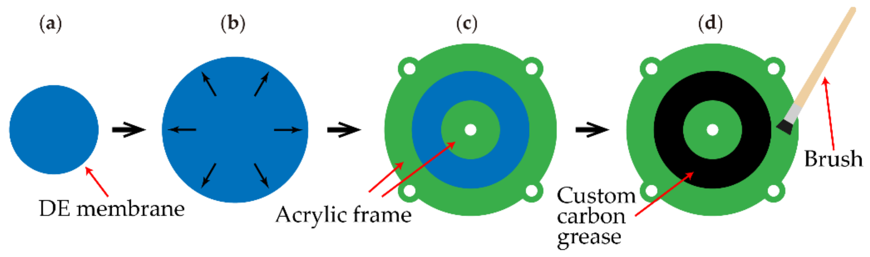
2.3.1. Fabrication Process

The fabrication process of the resonant-impact DEA system is summarized as follows. First, a piece of 100 μm thick silicone membrane (ELASTOSIL 2030, Wacker Chemie AG, Munich, Germany) was pre-stretched at the ratio of 1.1 × 1.1 before being bonded to a circular acrylic frame (20 mm ID) and a central disk (8 mm OD) to form a single unit. Second, custom carbon grease was hand-brushed onto both sides of the membrane to form the compliant electrodes. Copper tape was used to connect the high-voltage cables and the compliant electrodes. The fabrication process of a single unit is shown in Figure 3. The above steps were repeated twice to fabricate two identical units. Third, a Nylon rod was connected to the central disks of the two units, with the outer frames connected as well in order to deform the membranes out-of-plane by 2.5 mm each. A domed steel cap was fastened to the end of the rod close to the constraint to maximize the impact strength of the actuator. A piece of the acrylic beam with two ends clamped together was used as the constraint.

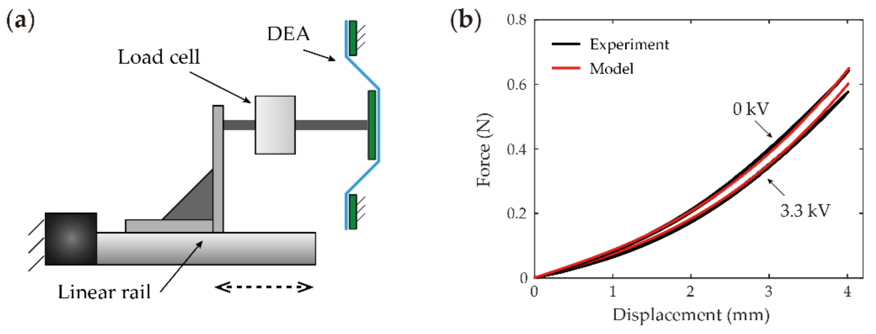
2.3.2. Experimental Setups and Model Validations

Quasi-static force-displacement characterization. The experimental setup is illustrated in Figure 4a. In this test, a single DEA unit was fixed to the testing rig and was deformed out-of-plane by a linear rail (X-LSQ150B-E01, ZABER, Vancouver, BC, Canada) from 0 to 4 mm, then returned at 0.05 mm/s. A load cell (S/N 835827, FUTEK, Irvine, CA, USA) measured the reaction force of the membrane and a laser displacement sensor (LK-G152 and LKGD500, Keyence, Osaka, Japan) measured the deformation. A DC voltage of 3.3 kV was applied to the DEA unit using a high voltage amplifier (10/40A-HS, TREK, Fort Collins, CA, USA) to characterize its electromechanical coupling effects. The measured and modelled force–displacement curves are plotted in Figure 4b, where the identified Ogden parameters in the model are μA = 3.15 × 10⁵ Pa and αA = 2.6. It can be noted that the model adopted in this work is able to characterize the force–displacement relationship of the DEA unit with good accuracy.
Frequency response characterization. The experimental setup is plotted in Figure 5a and is described as follows. The DEA and the constraint were horizontally mounted to the testing rig. The two units of the DEA were actuated by two anti-phase sinusoidal frequency sweep (0 to 150 Hz in 600 s) voltage signals with amplitudes of Φp-p = 1.7, 2.5 and 3.3 kV from two high-voltage amplifiers. The constraint gap G was adjusted manually using a high precision two-axis slider. Two laser displacement sensors were used to measure the displacements of the DEA and the center of the constraint, respectively, at a sampling rate of 40 kHz. Figure 5b,c plots the experimental and modelled forward frequency sweep results of the DEA, respectively, with G >> the resonant amplitude (i.e., the constraint has no effects on the dynamics). The identified modelling parameters are μB = 1.4 × 10⁵ Pa, αB = 2, ηB =1.4 × 10⁴, and ηA = 220. Note that the proposed model is able to characterize the frequency responses of the DEA accurately in all three voltage cases. The modelled frequency sweep results with constraint gap G = 0.6 mm are compared with the experimental results. It can be noted from Figure 5d,e that the impact model developed this work characterizes the resonant-impact responses with good accuracy.

3. Numerical and Experimental Study Results

3.1. Frequency Response Overview

To provide a general concept of the effects of the constraint on the frequency responses of the DEA, two sets of frequency responses curves are generated by using the nondimensional numerical model. These following values are adopted for the nondimensional variables and parameters in the simulations: Γ = 0.0045, μA/μB = 1, αA = 3, αB = 2, δA = 0.3, δB = 60, l = 0.8, k = 2.5 × 10³, and δi = 2, ϕp-p = 0.4. Unless specified otherwise, the same values are utilized in the rest of this paper. The simulated frequency response results of the DEA with no constraint (i.e., g = +∞) and with g = 0.1 are shown in Figure 6a,b, respectively. It can be noted from Figure 6a that the oscillation amplitude of the DEA with no constraint first increases with the increasing excitation frequency ωe, then peaks at its resonant frequency before dropping to a low value as the excitation frequency increases further, which is demonstrated in the experiments in Figure 6b as well. In addition, note that the forward and backward frequency response curves overlap completely. As a comparison, it can be observed from Figure 6b that the constraint results in strong distortions in the frequency response curves of the resonant-impact DEA system. Although the oscillation amplitudes increase with the increasing excitation frequency before resonance, the upper dead-end of the DEA can only increase to close to g, while the bottom dead-end continues to increase until its resonance. It is worth noting that the resonant frequency in the forward frequency step simulation in Figure 6b is much higher than that in the backward step due to the strong nonlinearity introduced by the constraint.
The amplitude of the impact force |f| (i.e., the largest force experienced by the constraint during an impact in a steady state response) against the excitation frequency is plotted in Figure 6c. It can be noted that the amplitude of the impact force |f| follows the same trend as the oscillation amplitude results in Figure 6b, which indicates that higher oscillation amplitudes lead to a larger impact force due to the higher energy level in the system. In the potential applications of such a resonant-impact DEA system (i.e., DEA-driven crawling robots) a larger impact force is desirable, as it typically means faster response/locomotion velocity or better performance in general. However, it is worth noting from Figure 6d that higher oscillation amplitudes (which lead to a larger impact force) can affect the stability of the system, as a small perturbation from the environment or the input can cause the high amplitude oscillation to lose its stability and transit into low amplitude oscillation. This is due to the multiple stable solutions in the resonant-impact DEA system near its resonance (i.e., the forward and backward frequency response curves do not overlap near the resonance in Figure 6b). This stability issue can significantly limit the controllability and robustness of the resonant-impact DEA system in practical applications where perturbations are unavoidable. To address this limitation, in this work we mainly focus on the impact frequency band (i.e., the overlapping region of the forward and backward curves), where a single stable solution exists. Despite the slightly lower oscillation amplitude and impact force amplitude, the system does not lose its stability (e.g., by jumping to low amplitude responses) in any cases, which maximizes its controllability and robustness. For this reason, in the rest of this work we restrict our studies to the impact frequency band where a single stable solution exists.

3.2. Effects of Excitation Voltage Amplitude

In this subsection, the effects of the excitation voltage amplitude on the performance of the resonant-impact DEA system are investigated both numerically and experimentally. In the nondimensional numerical simulation, the voltage amplitude ϕp-p is varied from 0.1 to 0.5 in 80 steps and the frequency responses from ωe = 0.01 to 4 in each voltage case are simulated. The oscillation amplitudes of the system ( a m p . = x m a x x m i n / 2 , where xmax and xmin are the maximum and minimum displacement at steady state, respectively) against the excitation voltage frequency ωe and amplitude ϕp-p are plotted in Figure 7a. It can be noted that |amp.| increases with the increasing voltage amplitude due to the higher input energy, while the frequency band with high-amplitude oscillations (the red region in Figure 7a) widens as well. The relationship between the peak frequency ωp (the frequency that yields the highest oscillation amplitude/impact force and maintains a single stable response) and peak impact force |fmax| (the impact force amplitude at ωp) against the voltage amplitude are plotted in Figure 7b. Note that no impact is triggered in this system when ϕp-p is small due to insufficient oscillation amplitude. As ϕp-p increases to ~0.19, impacts occur and ωp and |fmax| continue to increase with increasing ϕp-p.
In addition, the effects of excitation voltage amplitude on the resonant-impact DEA system were investigated in experiments with excitation voltage amplitudes Φp-p of 1.7, 2.1, 2.5, 2.9, 3.3, and 3.7 kV. Numerical simulations were conducted using the DEA design parameters listed in Section 2.3.1 and the modelling parameters from Section 2.3.2. The measured and corresponding modelling results for the peak frequency Ωp and peak oscillation amplitude |Amp.| (defined as the oscillation amplitude at frequency Ωp) are shown in Figure 8a. It can be seen that both Ωp and |Amp.| increase slightly with the Φp-p from 1.6 to 3.7 kV. On the other hand, note from Figure 8b that the peak impact force |Fmax| increases approximately linearly with the increasing voltage amplitude from ~0.2 N at Φp-p = 1.6 kV to over 1.3 N at 3.7 kV. All of these findings agree well with the results of the nondimensional studies shown in Figure 7.

3.3. Effects of Number of DEA Layers

To improve the output performance, multiple layers of DEAs can be stacked together to actuate in parallel, which enhances the power/work outputs. This subsection investigates the effects of the number of DEA layers on the frequency responses of the resonant-impact DEA system. First, through a non-dimensional numerical study, the layer number of the resonant-impact DEA system is varied from 1 to 8 with the other parameters remaining unchanged; the frequency response results are shown in Figure 9a. It can be noted that increasing the layer number leads to a higher peak frequency ωe, although it shows negligible influence on the peak oscillation amplitude. Figure 9b shows that the peak impact force |fmax| increases with the number of layers, which is as expected due to the multiplied power/work outputs. The |fmax| for the 8-layer case is more than twice that for the single-layer case.
The experimental and corresponding modelling results on the effects of the number of layers are shown in Figure 10, where 1, 2, and 3 layers of resonant-impact DEA systems were investigated. It can be noted from Figure 10 that while more layers of DEAs results in a higher peak frequency Ωp and peak impact force |Fmax|, there is a negligible effect on the peak amplitude |Amp.|; hence, the results successfully verify the findings reported in the nondimensional numerical study in Figure 9.

3.4. Effects of Constraint Gap

In this subsection, the effects of the constraint gap on the resonant-impact DEA system are investigated. In our nondimensional numerical simulation the nondimensional constraint gap g is varied from 0.02 to 0.2 in 80 steps, with the frequency response results plotted in Figure 11a. It can be noted that the frequency band at which impacts are triggered is reduced as g increases, while the oscillation amplitude peak increases. The reason for this is that as g increases (i.e., the constraint separates further from the DEA), the DEA is able to travel further, which increases its oscillation amplitude near its resonance. The relationships between g and the peak frequency ωp and peak impact force |fmax| are plotted in Figure 11b. Note that increasing the constraint gap g causes a continuous reduction in ωp. This results in a sharp drop in |fmax| from g = 0.02 to 0.04; however, as the g value increases further, |fmax| begins to fluctuate around ~5.2.
In the experimental study, the constraint gap G is varied from 0.2 to 1.6 mm with a step of 0.2 mm, and the results are plotted in Figure 12. It can be seen from Figure 12a that increasing G results in a gradual reduction in peak frequency Ωp. However, the peak amplitude |Amp.| increases approximately linearly with increasing G. These findings agree well with the nondimensional studies conducted in Figure 11. It should be noted that the peak impact force |Fmax| in this experimental study shows a slight fluctuation against the varying value of G. No sharp drop in |Fmax| is observed in Figure 12b in comparison with the nondimensional simulation results in Figure 11b, which is due to the lowest value of G being set at 0.2 mm in our experiments. In addition, note that the model’s predicted impact force values in Figure 12b are slightly higher than the measured data, which could be due to the nonideal impact condition in our experiments.

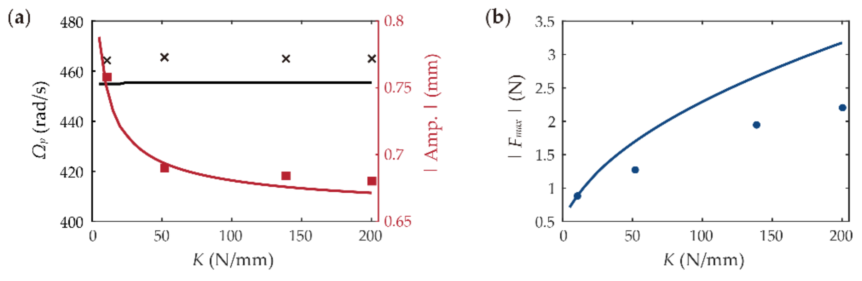
3.5. Effects of Constraint Stiffness

In addition to the constraint gap, the constraint stiffness can cause effects on the dynamics of the resonant-impact DEA system. In this nondimensional numerical study, the nondimensional stiffness k is varied from 100 to 2.5 × 10⁴ in 160 steps; the frequency response results are plotted in Figure 13a. It can be noted that varying the value of k has negligible effects on the peak frequency ωp and minor effects on the oscillation amplitude |amp.| of the system. However, as shown in Figure 13b, the increase in k results in the increase of the peak impact force |fmax|. Note that |fmax| is increased more than ten-fold when k is increased 100 to 2.5 × 10⁴.
To investigate the effects of constraint stiffness in our experiments, four pieces of acrylic beam with thicknesses of 1, 2, 3, and 4 mm were adopted as the constraint. Their equivalent stiffness was measured at K = 10.6, 51.9, 138.9, and 200.3 N/mm, respectively. The four acrylic beams were mounted such that the constraint gap maintained a constant value of G = 0.6 mm. Figure 14a shows that the peak frequency Ωp remains almost constant against the varying K, while its peak amplitude |Amp.| sees a minor reduction as K increases. The peak impact force |Fmax|, on the other hand, increases with increasing K, as shown in Figure 14b, which verifies the findings reported in the nondimensional numerical study in Figure 13b. The deviation between the experimental data and the modelling value in Figure 14b increases as K becomes larger, which could be due to a stiffer constraint causing a greater number of undesired shifts on the part of the impactor (a steel cap in this design) in the direction perpendicular to the impact.

4. Conclusions

In this work, the nonlinear dynamics of a resonant-impact DEA system were characterized in depth. Extensive numerical simulations and experimental validations were conducted to investigate the effects of several key parameters on the resonant-impact DEA system. The key findings of this paper are summarized as follows:
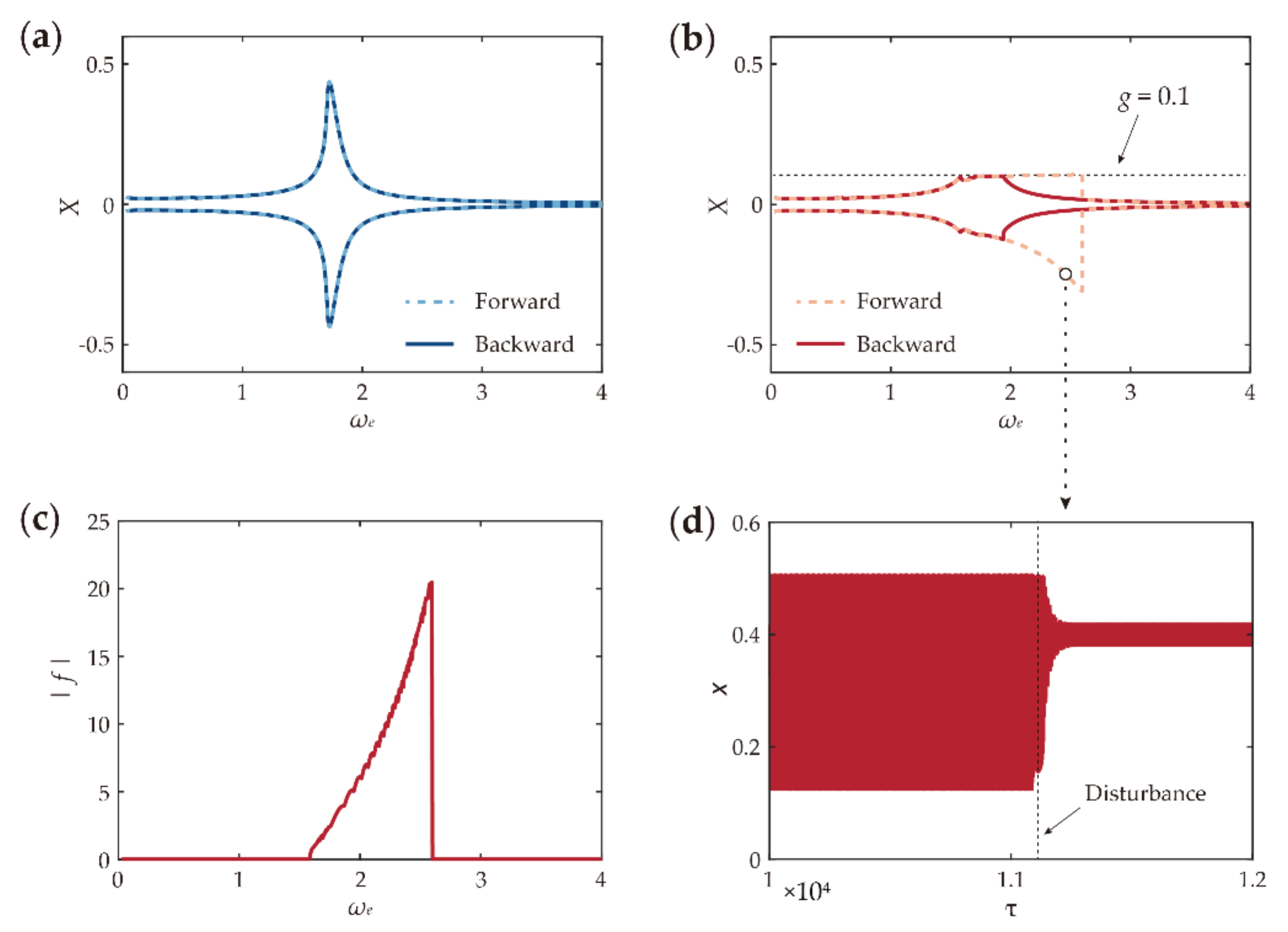
  • The constraint introduced in the impact system results in strong nonlinearity in the equation of motion, which causes severe distortion of the frequency response curves and shifts in the resonant frequencies towards larger values.
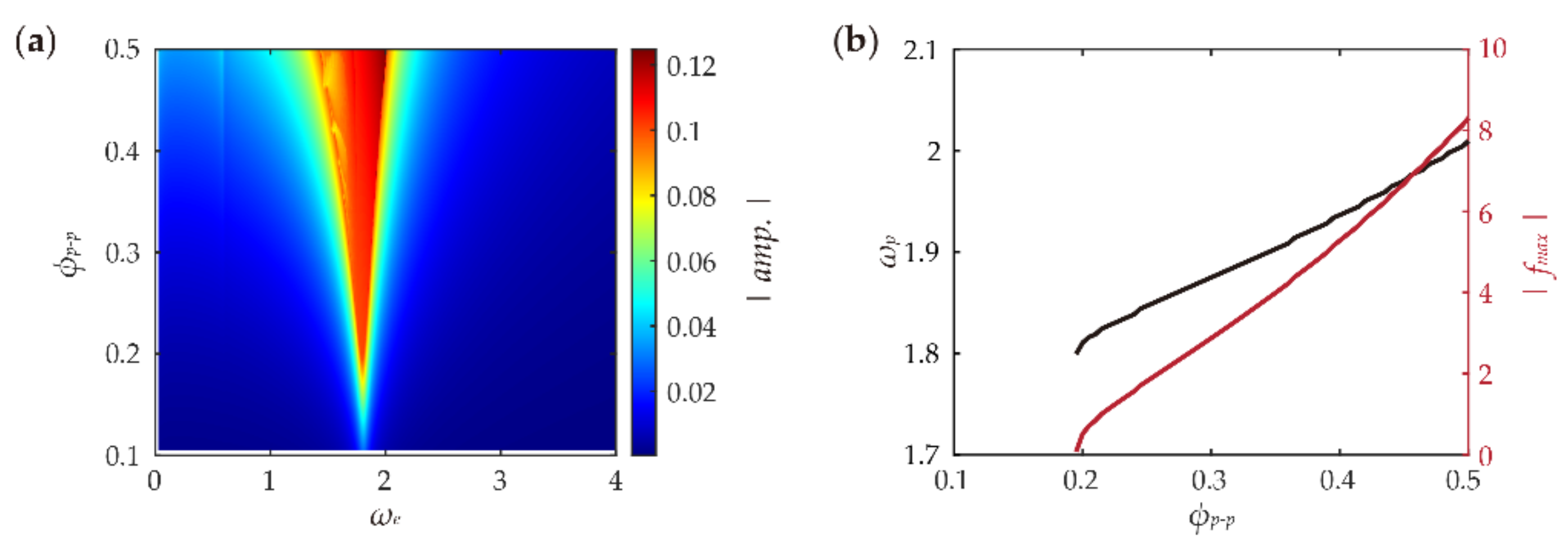
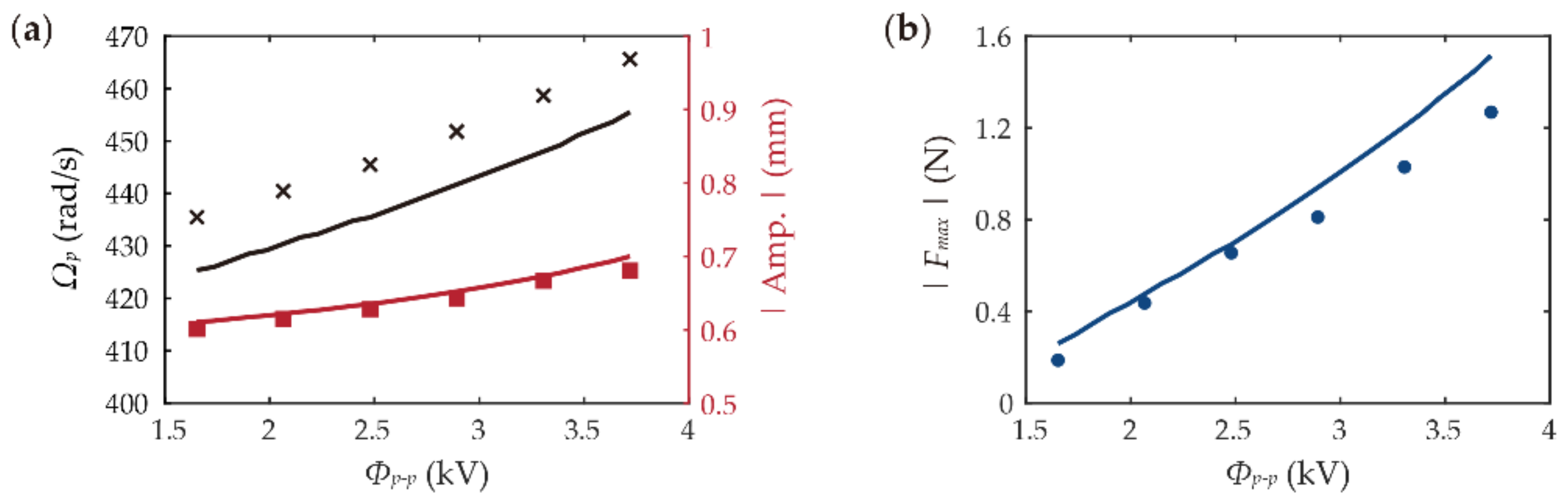
  • Increasing the excitation voltage amplitude simultaneously increases the peak oscillation amplitude, frequency, and impact force.
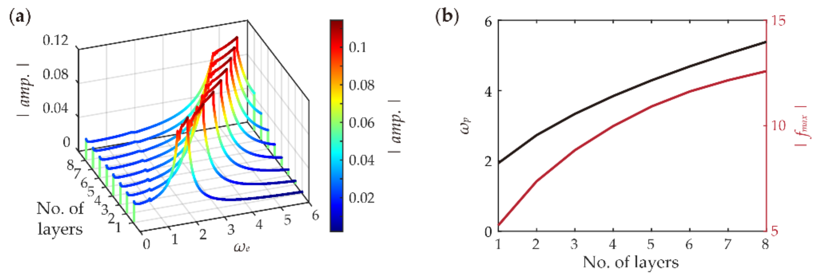
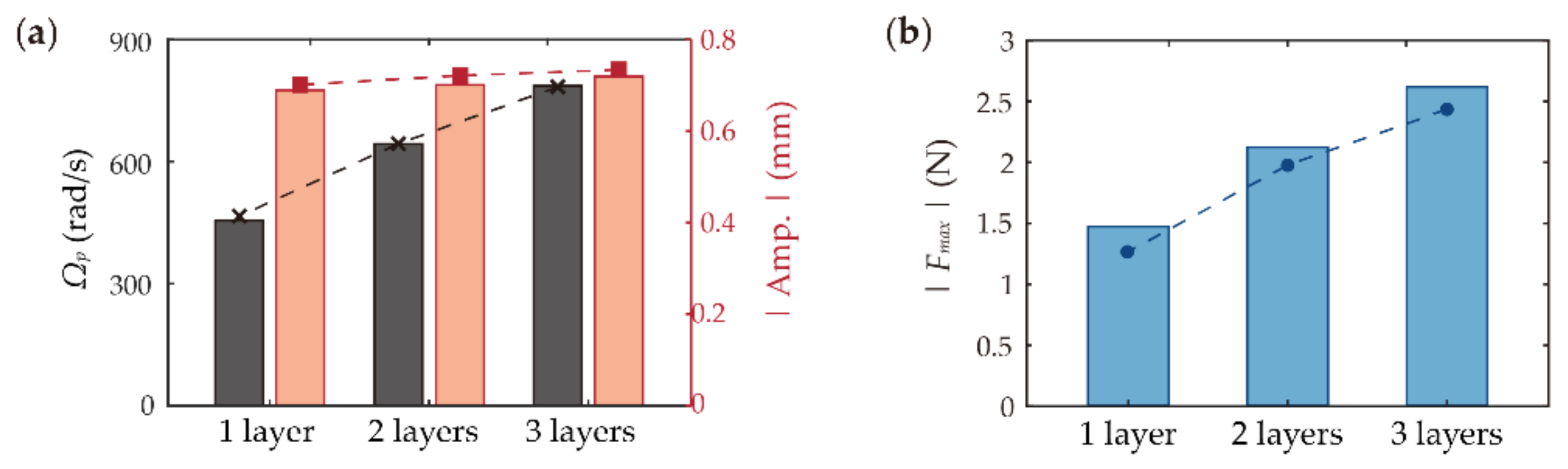
  • Although adding a greater number of DEA layers to the system can effectively increase the peak frequency and impact force, it shows negligible effects on the peak oscillation amplitude.
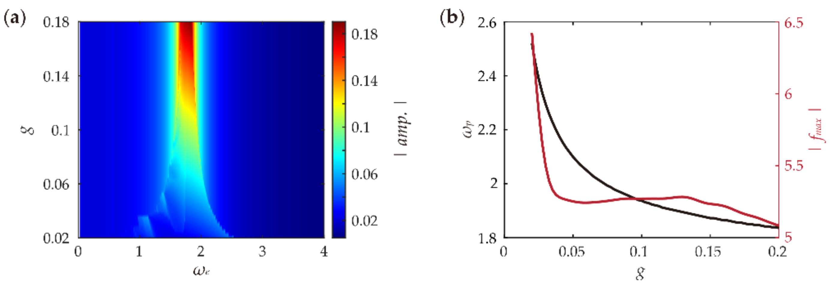
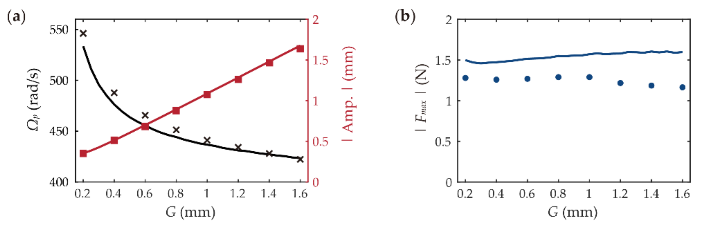
  • A wider constraint gap increases the peak oscillation amplitude of the system while at the same time reducing its peak frequency, and shows negligible effects on the peak impact force in a wide range.
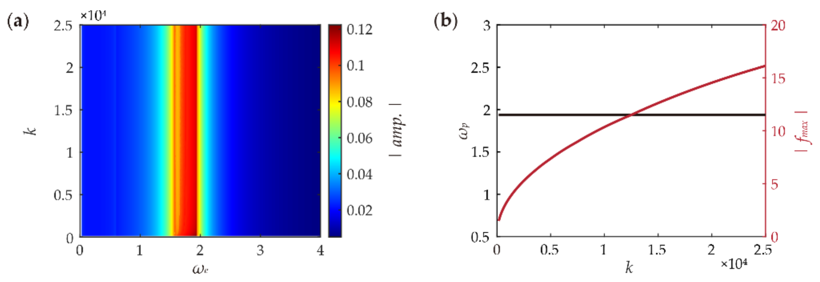
  • A stiffer constraint mainly contributes to increasing the peak impact force, while its effects on peak oscillation amplitude and frequency are minor.
In our previous study, we demonstrated that the proposed resonant-impact DEA system is capable of driving a crawling robot at a peak velocity over ten times faster compared with DEA driving systems with no resonant impacts. The findings reported in the present paper can provide valuable guidance for optimizing the previously proposed crawling robot to further improve its crawling performance. This work can offer guidelines for the design and performance optimization of other resonant-impact DEA-driven devices as well, for instance, energy harvesters and vibro-tactile applications.

Author Contributions

Methodology, C.C. and C.W.; validation, C.W., A.C. and X.G.; investigation, C.W.; resources, C.C.; writing—original draft preparation, C.C. and C.W.; writing—review and editing, C.C., A.C. and X.G.; visualization, A.C. and X.G.; supervision, C.C. All authors have read and agreed to the published version of the manuscript.

Funding

This research was funded in part by the National Natural Science Foundation of China (Grant No. 52105038), in part by the Guangdong Basic and Applied Basic Research Foundation (Grant No. 2020A1515110175), and in part by the Shenzhen Science and Technology Program (Grant No. JCYJ20210324115606018).

Institutional Review Board Statement

Not applicable.

Informed Consent Statement

Not applicable.

Data Availability Statement

Not applicable.

Conflicts of Interest

The authors declare no conflict of interest.

References

  1. Villani, V.; Pini, F.; Leali, F.; Secchi, C. Survey on human–robot collaboration in industrial settings: Safety, intuitive interfaces and applications. Mechatronics 2018, 55, 248–266. [Google Scholar] [CrossRef]
  2. Cherubini, A.; Passama, R.; Crosnier, A.; Lasnier, A.; Fraisse, P. Collaborative manufacturing with physical human–robot interaction. Robot. Comput. Integr. Manuf. 2016, 40, 1–13. [Google Scholar] [CrossRef] [Green Version]
  3. Zhang, D.; Zhang, N.; Ye, N.; Fang, J.; Han, X. Hybrid Learning Algorithm of Radial Basis Function Networks for Reliability Analysis. IEEE Trans. Reliab. 2020, 70, 887–900. [Google Scholar] [CrossRef]
  4. Wang, H.; Totaro, M.; Beccai, L. Toward Perceptive Soft Robots: Progress and Challenges. Adv. Sci. 2018, 5, 1800541. [Google Scholar] [CrossRef] [PubMed]
  5. Wang, C.; Sim, K.; Chen, J.; Kim, H.; Rao, Z.; Li, Y.; Chen, W.; Song, J.; Verduzco, R.; Yu, C. Soft Ultrathin Electronics Innervated Adaptive Fully Soft Robots. Adv. Mater. 2018, 30, e1706695. [Google Scholar] [CrossRef] [Green Version]
  6. Thuruthel, T.G.; Ansari, Y.; Falotico, E.; Laschi, C. Control Strategies for Soft Robotic Manipulators: A Survey. Soft Robot. 2018, 5, 149–163. [Google Scholar] [CrossRef]
  7. Pelrine, R.; Kornbluh, R.; Pei, Q.; Joseph, J. High-Speed Electrically Actuated Elastomers with Strain Greater Than 100%. Science 2000, 287, 836–839. [Google Scholar] [CrossRef]
  8. Cao, C.; Gao, X.; Conn, A.T. Towards efficient elastic actuation in bio-inspired robotics using dielectric elastomer artificial muscles. Smart Mater. Struct. 2019, 28, 095015. [Google Scholar] [CrossRef]
  9. Cao, C.; Gao, X.; Burgess, S.; Conn, A.T. Power optimization of a conical dielectric elastomer actuator for resonant robotic systems. Extrem. Mech. Lett. 2019, 35, 100619. [Google Scholar] [CrossRef]
  10. Christianson, C.; Goldberg, N.N.; Deheyn, D.D.; Cai, S.; Tolley, M.T. Translucent soft robots driven by frameless fluid electrode dielectric elastomer actuators. Sci. Robot. 2018, 3, eaat1893. [Google Scholar] [CrossRef]
  11. Duduta, M.; Berlinger, F.; Nagpal, R.; Clarke, D.R.; Wood, R.J.; Temel, F.Z. Tunable Multi-Modal Locomotion in Soft Dielectric Elastomer Robots. IEEE Robot. Autom. Lett. 2020, 5, 3868–3875. [Google Scholar] [CrossRef]
  12. Shintake, J.; Cacucciolo, V.; Shea, H.; Floreano, D. Soft Biomimetic Fish Robot Made of Dielectric Elastomer Actuators. Soft Robot. 2018, 5, 466–474. [Google Scholar] [CrossRef] [Green Version]
  13. Li, G.; Chen, X.; Zhou, F.; Liang, Y.; Xiao, Y.; Cao, X.; Zhang, Z.; Zhang, M.; Wu, B.; Yin, S.; et al. Self-powered soft robot in the Mariana Trench. Nature 2021, 591, 66–71. [Google Scholar] [CrossRef]
  14. Li, J.; Liu, L.; Liu, Y.; Leng, J. Dielectric Elastomer Spring-Roll Bending Actuators: Applications in Soft Robotics and Design. Soft Robot. 2019, 6, 69–81. [Google Scholar] [CrossRef]
  15. Xing, Z.; Zhang, J.; McCoul, D.; Cui, Y.; Sun, L.; Zhao, J. A Super-Lightweight and Soft Manipulator Driven by Dielectric Elastomers. Soft Robot. 2020, 7, 512–520. [Google Scholar] [CrossRef]
  16. Zhao, H.; Hussain, A.M.; Israr, A.; Vogt, D.M.; Duduta, M.; Clarke, D.R.; Wood, R.J. A Wearable Soft Haptic Communicator Based on Dielectric Elastomer Actuators. Soft Robot. 2020, 7, 451–461. [Google Scholar] [CrossRef]
  17. Lee, D.-Y.; Jeong, S.H.; Cohen, A.J.; Vogt, D.M.; Kollosche, M.; Lansberry, G.; Mengüç, Y.; Israr, A.; Clarke, D.R.; Wood, R.J. A Wearable Textile-Embedded Dielectric Elastomer Actuator Haptic Display. Soft Robot. 2022. ahead of print. [Google Scholar] [CrossRef]
  18. Tang, C.; Du, B.; Jiang, S.; Shao, Q.; Dong, X.; Liu, X.-J.; Zhao, H. A pipeline inspection robot for navigating tubular environments in the sub-centimeter scale. Sci. Robot. 2022, 7, eabm8597. [Google Scholar] [CrossRef]
  19. Cao, C.; Gao, X.; Conn, A.T. A Magnetically Coupled Dielectric Elastomer Pump for Soft Robotics. Adv. Mater. Technol. 2019, 4, 1900128. [Google Scholar] [CrossRef]
  20. Gu, G.; Zou, J.; Zhao, R.; Zhao, X.; Zhu, X. Soft wall-climbing robots. Sci. Robot. 2018, 3, eaat2874. [Google Scholar] [CrossRef]
  21. Chen, Y.; Zhao, H.; Mao, J.; Chirarattananon, P.; Helbling, E.F.; Hyun, N.-S.P.; Clarke, D.R.; Wood, R.J. Controlled flight of a microrobot powered by soft artificial muscles. Nature 2019, 575, 324–329. [Google Scholar] [CrossRef] [PubMed]
  22. Cao, C.; Chen, L.; Duan, W.; Hill, T.L.; Li, B.; Chen, G.; Li, H.; Li, Y.; Wang, L.; Gao, X. On the Mechanical Power Output Comparisons of Cone Dielectric Elastomer Actuators. IEEE/ASME Trans. Mechatron. 2021, 26, 3151–3162. [Google Scholar] [CrossRef]
  23. Duong, H.T.; Nguyen, V.-D.; Nguyen, H.-C.; Vu, N.-P.; Ngo, N.-K. A new design for bidirectional autogenous mobile systems with two-side drifting impact oscillator. Int. J. Mech. Sci. 2018, 140, 325–338. [Google Scholar] [CrossRef]
  24. Cao, Q.; Shi, H.; Xu, W.; Xiong, C.; Yang, Z.; Ji, R. Theoretical and Experimental Studies of Impact Energy and Rock-Drilling Efficiency in Vibro-Impact Drilling. J. Energy Resour. Technol. 2021, 144, 023201. [Google Scholar] [CrossRef]
  25. Afebu, K.O.; Liu, Y.; Papatheou, E. Application and comparison of feature-based classification models for multistable impact motions of percussive drilling. J. Sound Vib. 2021, 508, 116205. [Google Scholar] [CrossRef]
  26. Ghoneim, M.E.; Khan, Z.; Zuhra, S.; Ali, A.; Tag-Eldin, E. Numerical solution of Rosseland’s radiative and magnetic field effects for Cu-Kerosene and Cu-water nanofluids of Darcy-Forchheimer flow through squeezing motion. Alex. Eng. J. 2022, in press. [CrossRef]
  27. Moss, S.D.; McLeod, J.E.; Galea, S.C. Wideband vibro-impacting vibration energy harvesting using magnetoelectric transduction. J. Intell. Mater. Syst. Struct. 2012, 24, 1313–1323. [Google Scholar] [CrossRef]
  28. Serdukova, L.; Kuske, R.; Yurchenko, D. Stability and bifurcation analysis of the period-T motion of a vibroimpact energy harvester. Nonlinear Dyn. 2019, 98, 1807–1819. [Google Scholar] [CrossRef]
  29. Alhazmi, S.E.; Abdelmohsen, S.A.M.; Alyami, M.A.; Ali, A.; Asamoah, J.K.K. A Novel Analysis of Generalized Perturbed Zakharov–Kuznetsov Equation of Fractional-Order Arising in Dusty Plasma by Natural Transform Decomposition Method. J. Nanomater. 2022, 2022, 7036825. [Google Scholar] [CrossRef]
  30. Nguyen, K.-T.; La, N.-T.; Ho, K.-T.; Ngo, Q.-H.; Chu, N.-H.; Nguyen, V.-D. The effect of friction on the vibro-impact locomotion system: Modeling and dynamic response. Meccanica 2021, 56, 2121–2137. [Google Scholar] [CrossRef]
  31. Guo, B.; Ley, E.; Tian, J.; Zhang, J.; Liu, Y.; Prasad, S. Experimental and numerical studies of intestinal frictions for propulsive force optimisation of a vibro-impact capsule system. Nonlinear Dyn. 2020, 101, 65–83. [Google Scholar] [CrossRef]
  32. Li, S.; Yan, L.; Li, W.; Zhao, H.; Ling, X. Research on Energy Response Characteristics of Rock under Harmonic Vibro-Impacting Drilling. J. Vib. Eng. Technol. 2019, 7, 487–496. [Google Scholar] [CrossRef] [Green Version]
  33. Liu, Y.; Chávez, J.P.; Pavlovskaia, E.; Wiercigroch, M. Analysis and control of the dynamical response of a higher order drifting oscillator. Proc. R. Soc. A Math. Phys. Eng. Sci. 2018, 474, 20170500. [Google Scholar] [CrossRef]
  34. Moss, S.D.; Barry, A.; Powlesland, I.; Galea, S.; Carman, G.P. A low profile vibro-impacting energy harvester with symmetrical stops. Appl. Phys. Lett. 2010, 97, 234101. [Google Scholar] [CrossRef]
  35. Guo, B.; Ringwood, J.V. Non-Linear Modeling of a Vibro-Impact Wave Energy Converter. IEEE Trans. Sustain. Energy 2020, 12, 492–500. [Google Scholar] [CrossRef]
  36. Guo, B.; Liu, Y.; Birler, R.; Prasad, S. Self-propelled capsule endoscopy for small-bowel examination: Proof-of-concept and model verification. Int. J. Mech. Sci. 2020, 174, 105506. [Google Scholar] [CrossRef]
  37. Wu, C.; Yan, H.; Cai, A.; Cao, C. A Dielectric Elastomer Actuator-Driven Vibro-Impact Crawling Robot. Micromachines 2022, 13, 1660. [Google Scholar] [CrossRef]
  38. Hau, S.; Rizzello, G.; Seelecke, S. A novel dielectric elastomer membrane actuator concept for high-force applications. Extreme Mech. Lett. 2018, 23, 24–28. [Google Scholar] [CrossRef]
  39. Cao, C.; Chen, L.; Hill, T.L.; Wang, L.; Gao, X. Exploiting Bistability for High-Performance Dielectric Elastomer Resonators. IEEE/ASME Trans. Mechatron. 1–12. [CrossRef]
  40. Cao, C.; Chen, L.; Li, B.; Chen, G.; Nie, Z.; Wang, L.; Gao, X. Toward broad optimal output bandwidth dielectric elastomer actuators. Sci. China Technol. Sci. 2022, 65, 1137–1148. [Google Scholar] [CrossRef]
  41. Ogden, R.W. Large deformation isotropic elasticity—On the correlation of theory and experiment for incompressible rubberlike solids. Proc. R. Soc. London. Ser. A Math. Phys. Sci. 1972, 326, 565–584. [Google Scholar] [CrossRef]
  42. Zhang, J.; Ru, J.; Chen, H.; Li, D.; Lu, J. Viscoelastic creep and relaxation of dielectric elastomers characterized by a Kelvin-Voigt-Maxwell model. Appl. Phys. Lett. 2017, 110, 044104. [Google Scholar] [CrossRef]
  43. Foo, C.C.; Cai, S.; Koh, S.J.A.; Bauer, S.; Suo, Z. Model of dissipative dielectric elastomers. J. Appl. Phys. 2012, 111, 034102. [Google Scholar] [CrossRef]
Figure 1. (a) Schematic diagram of the resonant-impact DEA system. (b) Motion of the resonant-impact DEA system in one typical impact oscillation cycle. (c) Displacement of the moving mass and the reaction force on the supporting rig. Red curves: proposed resonant-impact DEA system; blue curves: identical DEA without the impact constraint.
Asi 05 00122 g001
Figure 2. (a) Sketch of the resonant-impact DEA system model and (b) illustration of the material model.
Asi 05 00122 g002
Figure 3. Illustration of the fabrication process of a single unit. (a) The initial state of the DE membrane. (b) Pre-stretching of the membrane. (c) Bonding to acrylic frames. (d) Hand-brushing custom carbon grease.
Asi 05 00122 g003
Figure 4. (a) Experimental setup of the quasi-static force-displacement characterization and (b) comparison of the experimental and modelling force-displacement results.
Asi 05 00122 g004
Figure 5. (a) Experimental setup of the frequency response characterization. (b) Measured forward frequency sweep results of the DEA with G >> resonant amplitude and at voltage amplitudes of 1.7, 2.5, and 3.3 kV. (c) Modelling results of the DEA at the same voltage cases. (d) Measured frequency sweep results of the resonant-impact DEA system with G = 0.6 mm. (e) Modelling results of the resonant-impact DEA system.
Asi 05 00122 g005
Figure 6. Frequency sweep results of the DEA (a) without constraint and (b) with constraint, ϕp-p = 0.4, g = 0.1; here, X is the maximum/minimum displacement at steady state. (c) Impact force amplitude |f| of the resonant-impact DEA system against the excitation frequency ωe. (d) Demonstration of the resonant-impact DEA system losing its stability when experiencing a disturbance in its excitation voltage signals.
Asi 05 00122 g006
Figure 7. (a) Effects of excitation voltage amplitude on the frequency responses of the resonant-impact DEA system and (b) effects of excitation voltage amplitude on the peak frequency and peak impact force.
Asi 05 00122 g007
Figure 8. Experimental and modelling results on the effects of excitation voltage amplitude on (a) peak frequency and oscillation amplitude and (b) peak impact force. The discrete markers represent the experimental data and the continuous curves are the modelling results.
Asi 05 00122 g008
Figure 9. Effects of the number of DEA layers on (a) the frequency responses and (b) the peak frequency and peak impact force of the resonant-impact DEA system.
Asi 05 00122 g009
Figure 10. Experimental and modelling results on the effects of number of DEA layers on (a) peak frequency and oscillation amplitude and (b) peak impact force. The solid bars are the experimental data and the dashed lines with markers are the modelling results.
Asi 05 00122 g010
Figure 11. Effects of constraint gap on (a) the frequency responses of the resonant-impact DEA system and (b) the peak frequency and peak impact force.
Asi 05 00122 g011
Figure 12. Experimental and modelling results of the effects of the constraint gap on (a) the peak frequency and oscillation amplitude and (b) the peak impact force. The discrete markers indicate experimental data, while the continuous curves are the modelling results.
Asi 05 00122 g012
Figure 13. (a) Effects of constraint stiffness on the frequency responses of the resonant-impact DEA system and (b) effects of constraint stiffness on the peak frequency and peak impact force.
Asi 05 00122 g013
Figure 14. Experimental and modelling results on the effects of constraint stiffness on (a) peak frequency and oscillation amplitude and (b) peak impact force. The discrete markers indicate the experimental data and the continuous curves are the modelling results.
Asi 05 00122 g014
Publisher’s Note: MDPI stays neutral with regard to jurisdictional claims in published maps and institutional affiliations.

