
Improvement of the Sensor Capability of the NAO Robot by the Integration of a Laser Rangefinder


Abstract
:1. Introduction
2. Materials and Methods
2.1. NAO6—Aldebaran, Part of United Robotics Group
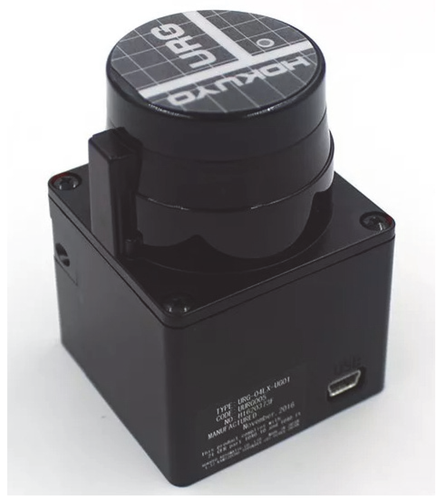
2.2. Autonomous Navigation and “Range Finder” Sensors
- Time of flight measurement;
- Measurement of phase shift.
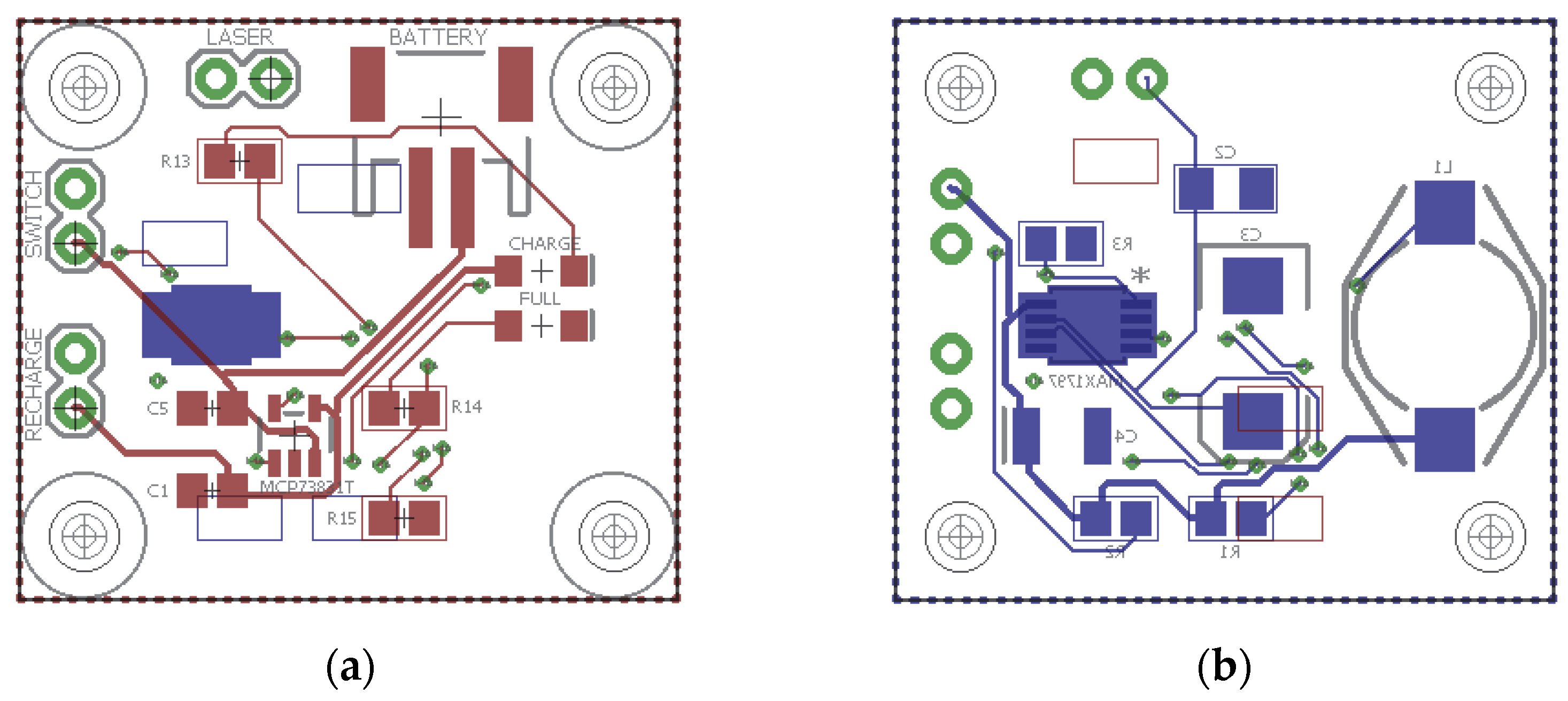
2.3. Rangefinder Power Supply Circuit Design
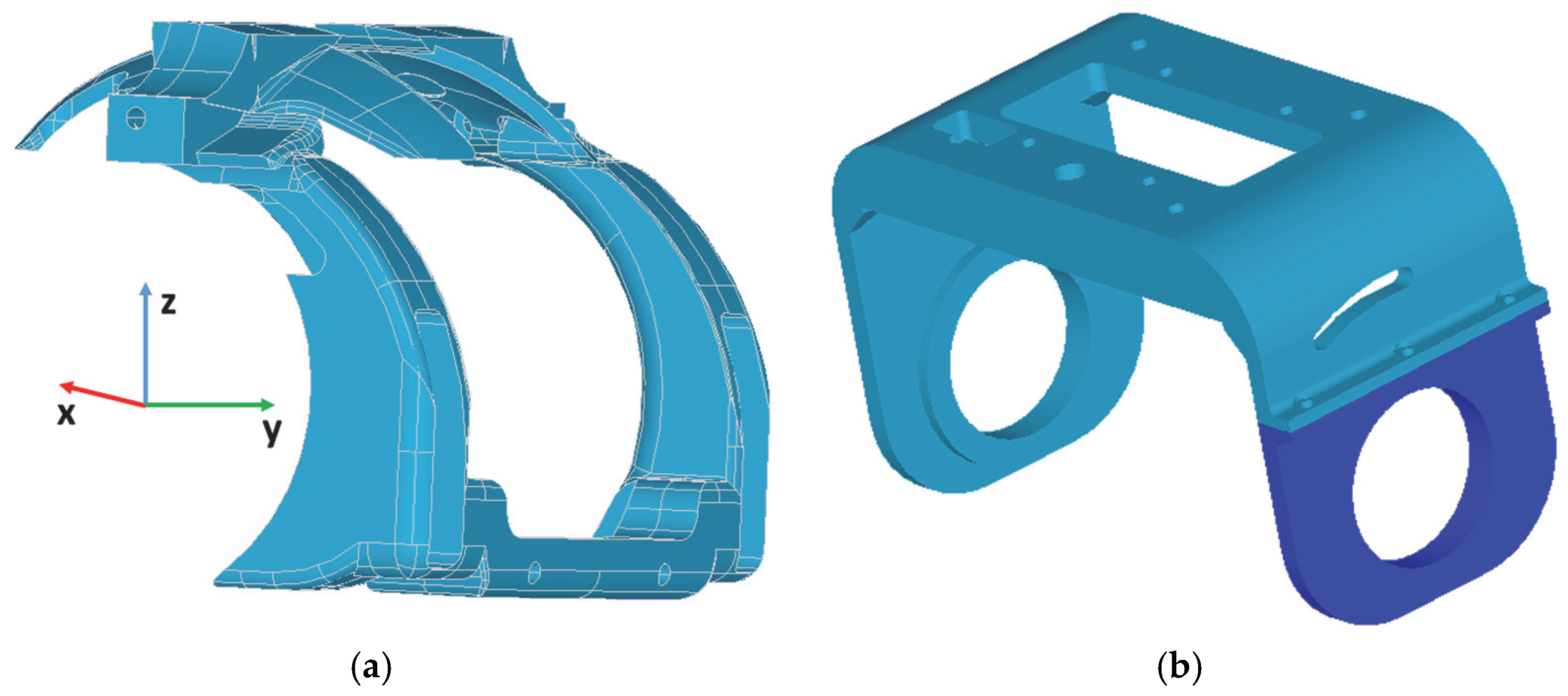
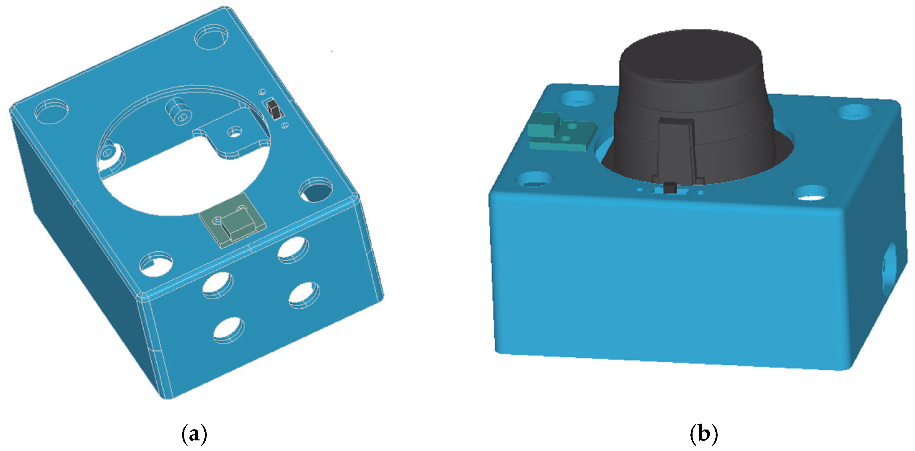
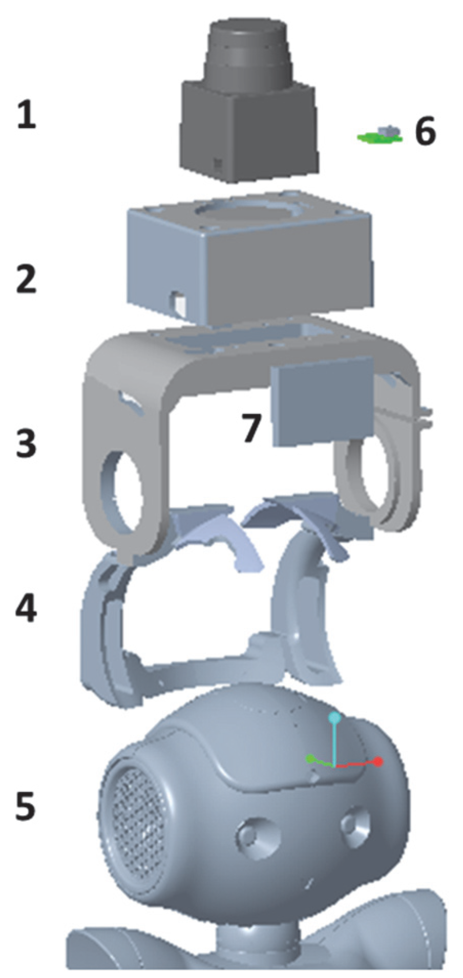
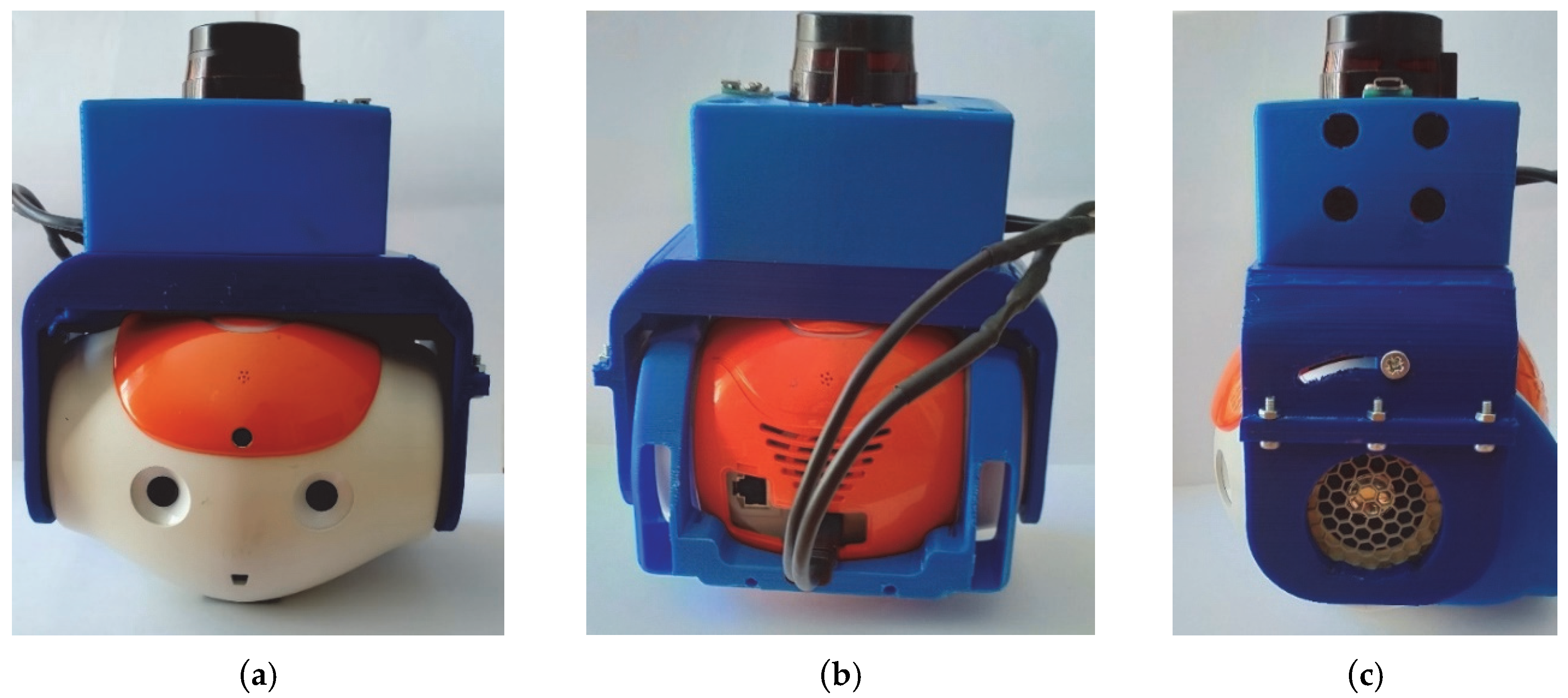
2.4. Design and Manufacturing of the Helmet
3. Results
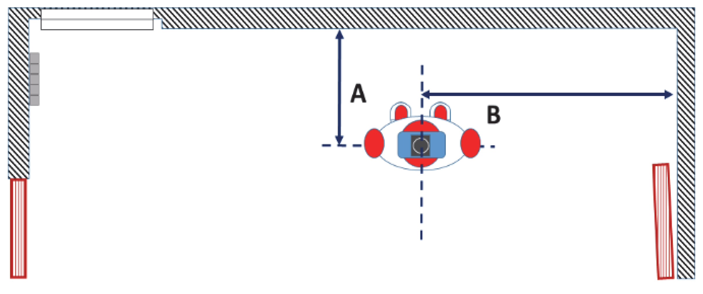
3.1. Experimental Setup
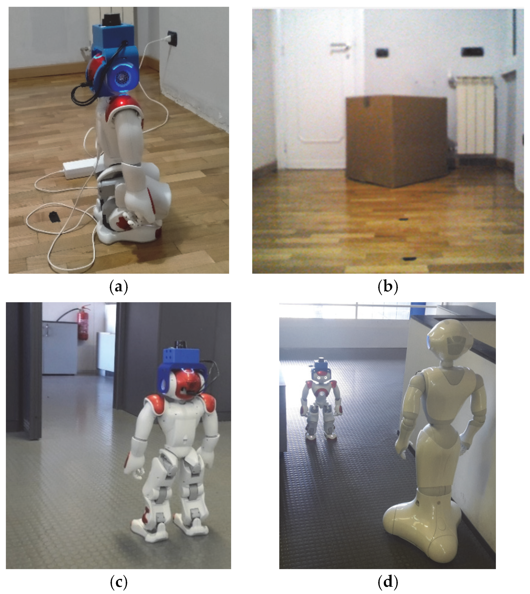
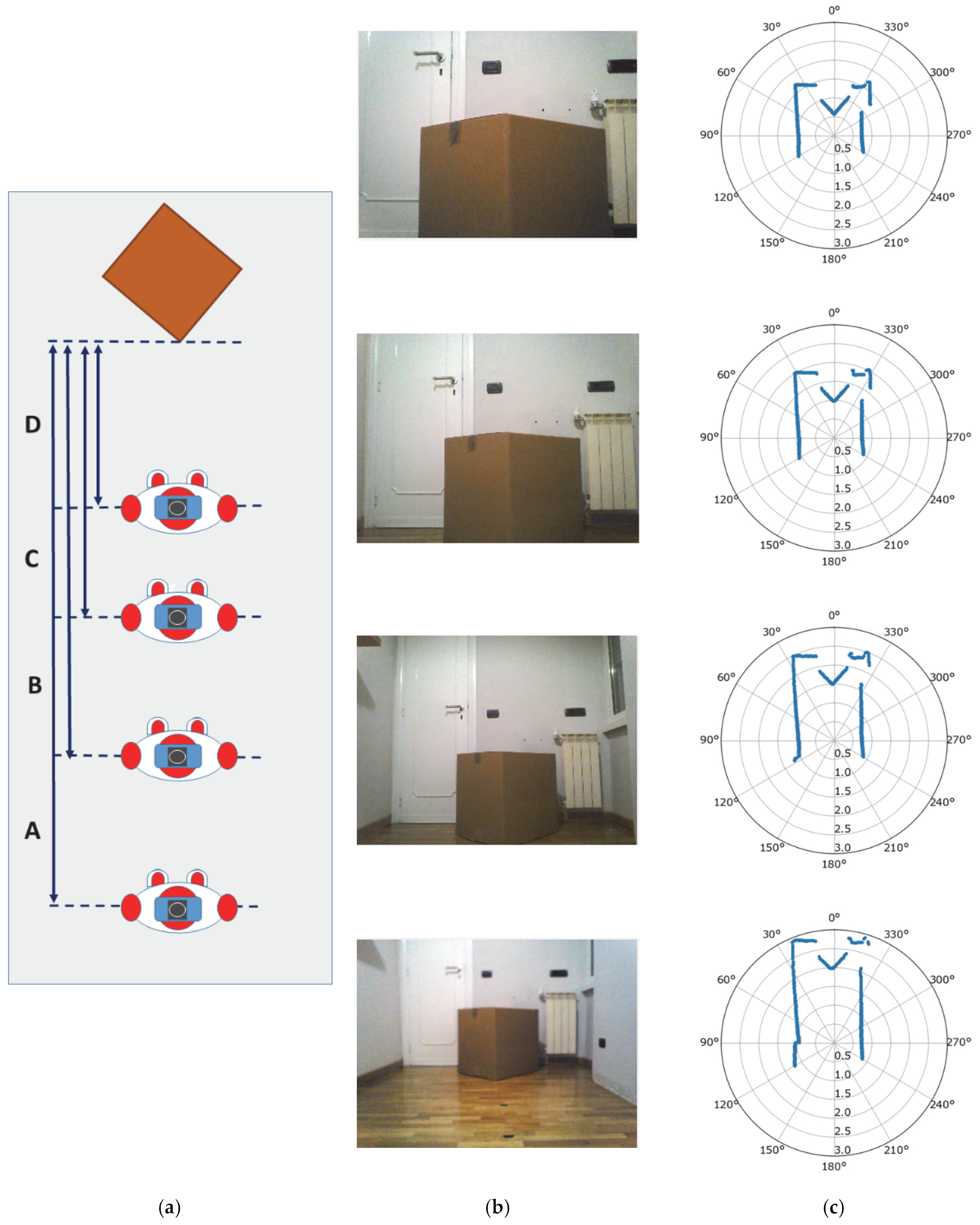
- Scenario #1: The robot NAO is moving in an environment of fixed objects. It is advancing towards an obstacle that consists of a large box placed at an initial distance of 200 cm (Figure 8b).
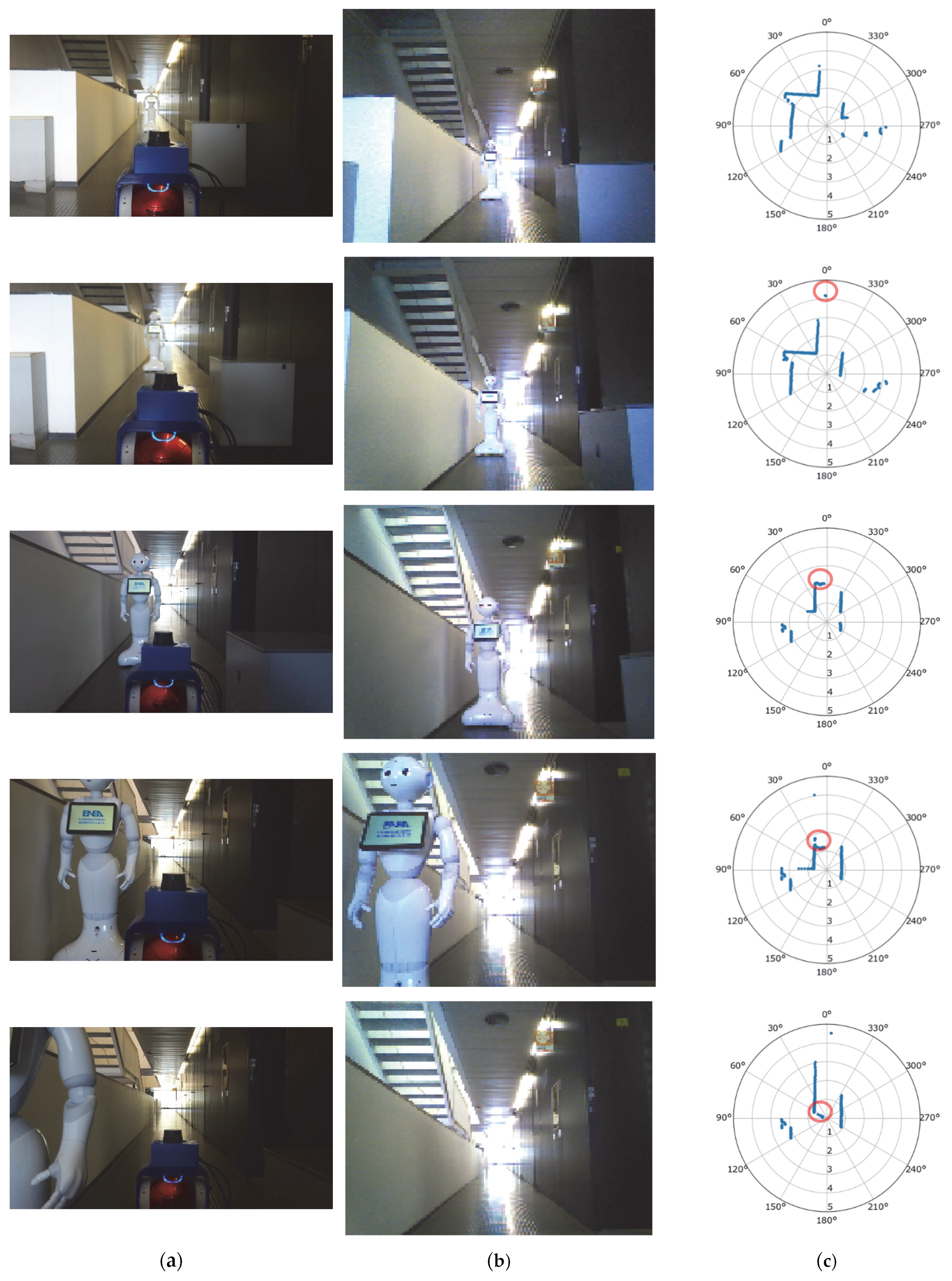
- Scenario #3: The NAO robot is advancing in an environment where other objects are also in movement (i.e., the Pepper Robot—see Figure 8d). In particular, it was initially placed in a wide corridor at a distance from the second robot of more than 500 cm (maximum detectable range for the sensor). The acquisition of data began when both robots started to move toward each other.
3.2. Measurement Results
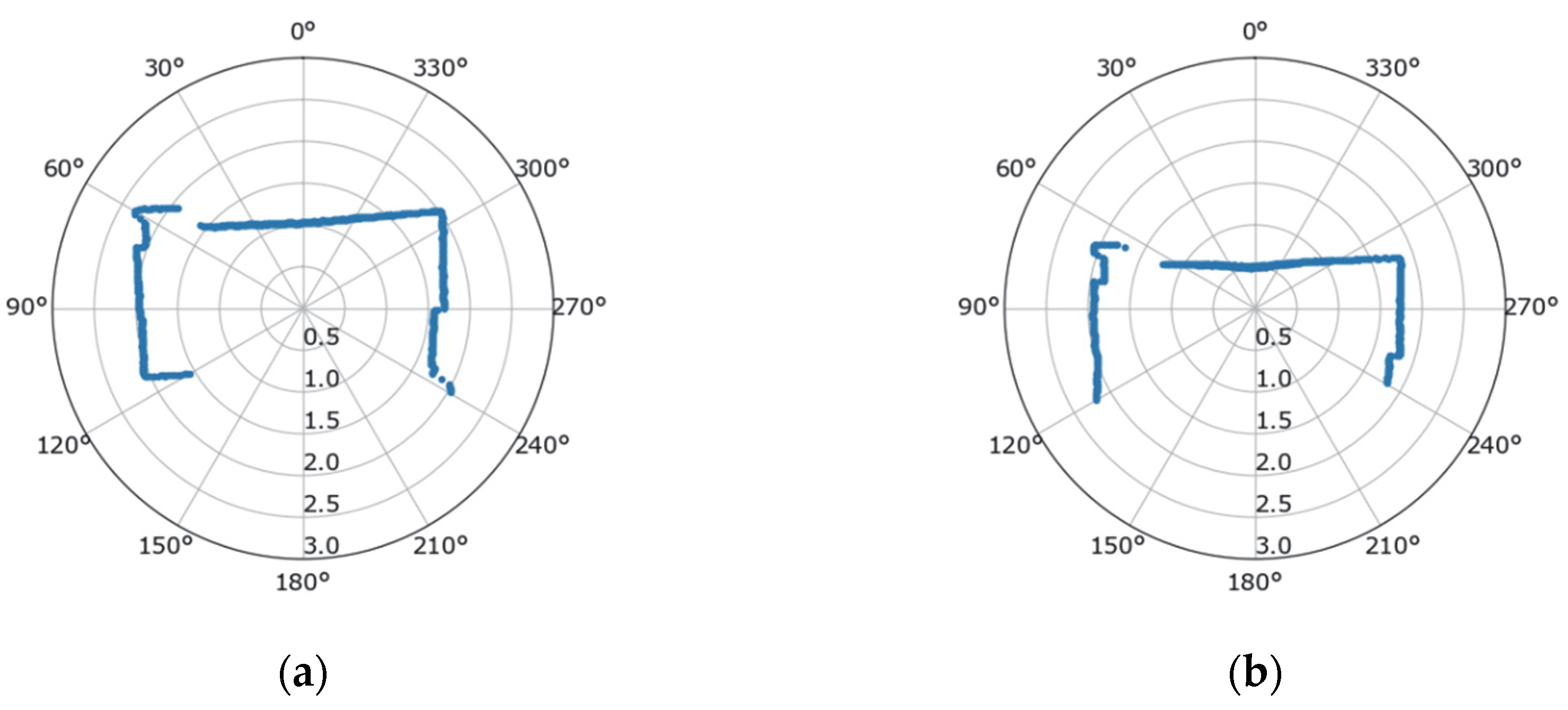
3.2.1. Test#1 Measurement Results
3.2.2. Test #2 Measurement Results
Scenario #1
Scenario #2
Scenario #3
4. Discussion
5. Conclusions
Author Contributions
Funding
Conflicts of Interest
References
- World Population Ageing 2019 the United Nations. Available online: https://www.un.org/en/development/desa/population/publications/pdf/ageing/WorldPopulationAgeing2019-Highlights.pdf (accessed on 20 September 2022).
- Ageing Europe Statistics on Population Developments. Available online: https://ec.europa.eu/eurostat/statistics-explained/index.php?title=Ageing_Europe_-_statistics_on_population_developments (accessed on 20 September 2022).
- Ageing Europe. Looking at the Lives of Older People in the EU. Eurostat 2019 Report. Available online: https://www.age-platform.eu/publications/ageing-europe-looking-lives-older-people-eu-eurostat-2019-report (accessed on 20 September 2022).
- Available online: https://www.enea.it/en/international-activities/eu-activities/strategic-initiatives/ambient-assisted-living-aal (accessed on 20 September 2022).
- Tinker, A.; Kellaher, L.; Ginn, J.; Ribe, E. Assisted Living Platform—The Long Term Care Revolution; Housing LIN: London, UK, 2013. [Google Scholar]
- Savage, N. Robots rise to meet the challenge of caring for old people. Nature 2022, 601, S8–S10. [Google Scholar] [CrossRef] [PubMed]
- Botticelli, M.; Monteriù, A.; Zanela, A.; Romano, S. Smart Homes and Assisted Living as an Additional Service Offered to the Users. In Proceedings of the 2019 IEEE 9th International Conference on Consumer Electronics (ICCE-Berlin), Berlin, Germany, 8–11 September 2019. [Google Scholar]
- Betriana, F.; Tanioka, R.; Gunawan, J.; Locsin, R.C. Healthcare Robots and Human Generations: Consequences for Nursing and Healthcare. Collegian 2022, 29, 767–773. [Google Scholar] [CrossRef]
- Jecker, N.S. You’ve got a friend in me: Sociable robots for older adults in an age of global pandemics. Ethic Inf. Technol. 2021, 23, 35–43. [Google Scholar] [CrossRef] [PubMed]
- Franke, A.; Nass, E.; Piereth, A.-K.; Zettl, A.; Heidl, C. Implementation of Assistive Technologies and Robotics in Long-Term Care Facilities: A Three-Stage Assessment Based on Acceptance, Ethics, and Emotions. Front. Psychol. 2021, 12, 694297. [Google Scholar] [CrossRef] [PubMed]
- Shuhaiber, A.; Mashal, I. Understanding users’ acceptance of smart homes. Technol. Soc. 2019, 58, 101110. [Google Scholar] [CrossRef]
- Daruwala, N.A.; Oberst, U. Individuals’ Intentions to Use Smart Home Technology: The Role of Needs Satisfaction and Frustration, Technology Acceptance and Technophobia. Available online: https://ssrn.com/abstract=4061510 (accessed on 20 September 2022).
- Sohn, K.; Kwon, O. Technology acceptance theories and factors influencing artificial Intelligence-based intelligent products. Telemat. Inform. 2020, 47, 101324. [Google Scholar] [CrossRef]
- Ben Jemaa, A.; Irato, G.; Zanela, A.; Brescia, A.; Turki, M.; Jaidane, M. Congruent Auditory Display and Front-Back Confusion in Sound Localization: Case of Elderly Driver. J. Transp. Res. Part F Traffic Psychol. Behav. 2018, 59, 524–534. [Google Scholar] [CrossRef]
- Pal, D.; Funilkul, S.; Vanijja, V.; Papasratorn, B. Analyzing the Elderly Users’ Adoption of Smart-Home Services. IEEE Access 2018, 6, 51238–51252. [Google Scholar] [CrossRef]
- Aymerich-Franch, L. Why it is time to stop ostracizing social robots. Nat. Mach. Intell. 2020, 2, 364. [Google Scholar] [CrossRef]
- Li, R.; Oskoei, M.A.; Hu, H. Towards ROS Based Multi-robot Architecture for Ambient Assisted Living. In Proceedings of the 2013 IEEE International Conference on Systems, Man, and Cybernetics, Manchester, UK, 13–16 October 2013; pp. 3458–3463. [Google Scholar] [CrossRef]
- Mayer, P.; Beck, C.; Panek, P. Examples of multimodal user interfaces for socially assistive robots in Ambient Assisted Living environments. In Proceedings of the 2012 IEEE 3rd International Conference on Cognitive Infocommunications (CogInfoCom), Kosice, Slovakia, 2–5 December 2012; pp. 401–406. [Google Scholar] [CrossRef]
- Pirhonen, J.; Tiilikainen, E.; Pekkarinen, S.; Lemivaara, M.; Melkas, H. Can robots tackle late-life loneliness? Scanning of future opportunities and challenges in assisted living facilities. Futures 2020, 124, 102640. [Google Scholar] [CrossRef]
- Gomez-Donoso, F.; Escalona, F.; Rivas, F.M.; Cañas, J.M.; Cazorla, M. Enhancing the Ambient Assisted Living Capabilities with a Mobile Robot. Comput. Intell. Neurosci. 2019, 2019, 9412384. [Google Scholar] [CrossRef]
- Mahmood, S.; Ampadu, K.O.; Antonopoulos, K.; Panagiotou, C.; Mendez, S.A.P.; Podlubne, A.; Antonopoulos, C.; Keramidas, G.; Hübner, M.; Goehringer, D.; et al. Prospects of Robots in Assisted Living Environment. Electronics 2021, 10, 2062. [Google Scholar] [CrossRef]
- Bui, H.-D.; Chong, N.Y. An Integrated Approach to Human-Robot-Smart Environment Interaction Interface for Ambient Assisted Living. In Proceedings of the 2018 IEEE Workshop on Advanced Robotics and Its Social Impacts (ARSO), Genova, Italy, 27–29 September 2018; pp. 32–37. [Google Scholar] [CrossRef]
- De Freese, V.; Wright, T.; Robalino, I.; Vesonder, G. Robotic Solutions for Eldercare. In Proceedings of the 2019 IEEE 10th Annual Ubiquitous Computing, Electronics & Mobile Communication Conference (UEMCON), New York, NY, USA, 10–12 October 2019; pp. 389–394. [Google Scholar] [CrossRef]
- Jia, Y.; Zhang, B.; Li, M.; King, B.; Meghdari, A. Human-Robot Interaction. Journal of Robotics 2018, 2018, 3879547. [Google Scholar] [CrossRef]
- Torta, E.; Oberzaucher, J.; Werner, F.; Cuijpers, R.H.; Juola, J.F. Attitudes toward socially assistive robots in intelligent homes: Results from laboratory studies and field trials. J. Hum. Robot. Interact. 2012, 1, 76–99. [Google Scholar] [CrossRef] [Green Version]
- Onyeulo, E.B.; Gandhi, V. What Makes a Social Robot Good at Interacting with Humans? Information 2020, 11, 43. [Google Scholar] [CrossRef] [Green Version]
- Keizer, R.A.O.; van Velsen, L.; Moncharmont, M.; Riche, B.; Ammour, N.; Del Signore, S.; Zia, G.; Hermens, H.; N’Dja, A. Using socially assistive robots for monitoring and preventing frailty among older adults: A study on usability and user experience challenges. Health Technol. 2019, 9, 595–605. [Google Scholar] [CrossRef]
- Available online: https://https://www.aldebaran.com/en/nao (accessed on 20 September 2022).
- Recio, D.L.; Segura, L.M.; Segura, E.M.; Waern, A. The NAO models for the elderly. In Proceedings of the 2013 8th ACM/IEEE International Conference on Human-Robot Interaction (HRI), Tokyo, Japan, 3–6 March 2013; pp. 187–188. [Google Scholar] [CrossRef]
- Robaczewski, A.; Bouchard, J.; Bouchard, K.; Gaboury, S. Socially Assistive Robots: The Specific Case of the NAO. Int. J. Soc. Robot. 2021, 13, 795–831. [Google Scholar] [CrossRef]
- Blavette, L.; Rigaud, A.-S.; Anzalone, S.M.; Kergueris, C.; Isabet, B.; Dacunha, S.; Pino, M. A Robot-Mediated Activity Using the Nao Robot to Promote COVID-19 Precautionary Measures among Older Adults in Geriatric Facilities. Int. J. Environ. Res. Public Health 2022, 19, 5222. [Google Scholar] [CrossRef]
- Andreasson, R.; Alenljung, B.; Billing, E.; Lowe, R. Affective Touch in Human–Robot Interaction: Conveying Emotion to the Nao Robot. Int. J. Soc. Robot. 2018, 10, 473–491. [Google Scholar] [CrossRef] [Green Version]
- Robot Operating System. Available online: https://www.ros.org (accessed on 20 September 2022).
- Joglekar, P.; Kulkarni, V. Humanoid Robot as a Companion for the Senior Citizens. In Proceedings of the 2018 IEEE Punecon, Pune, India, 30 November–2 December 2018; pp. 1–4. [Google Scholar]
- Ghosh, R.; Khan, N.; Migovich, M.; Wilson, D.; Latshaw, E.; Tate, J.A.; Mion, L.C.; Sarkar, N. Iterative User Centered Design of Robot-Mediated Paired Activities for Older Adults with Mild Cognitive Impairment (MCI). In Proceedings of the International Conference on Human-Computer Interaction, Tashkent, Uzbekistan, 20–22 October 2022; Springer: Cham, Switzerland, 2022; pp. 14–28. [Google Scholar]
- Arent, K.; Kruk-Lasocka, J.; Niemiec, T.; Szczepanowski, R. Social robot in diagnosis of autism among preschool children. In Proceedings of the 2019 24th International Conference on Methods and Models in Automation and Robotics (MMAR), Międzyzdroje, Poland, 26–29 August 2019; pp. 652–656. [Google Scholar]
- Lytridis, C.; Vrochidou, E.; Chatzistamatis, S.; Kaburlasos, V. Social engagement interaction games between children with Autism and humanoid robot NAO. In Proceedings of the 13th International Conference on Soft Computing Models in Industrial and Environmental Applications, San Sebastian, Spain, 6–8 June 2018; Springer: Cham, Switzerland, 2018; pp. 562–570. [Google Scholar]
- Assad-Uz-Zaman, M.; Rasedul Islam, M.; Miah, S.; Rahman, M.H. NAO robot for cooperative rehabilitation training. J. Rehabil. Assist. Technol. Eng. 2019, 6, 2055668319862151. [Google Scholar] [CrossRef] [Green Version]
- Siddique, T.; Al Marzooqi, R.; Alleem, H.R.; Fareh, R.; Baziyad, M.S.; Elsabe, A.Y.H. Evaluation of UE Exercises using NAO Robot for Poststroke Disabilities. In Proceedings of the 2022 Advances in Science and Engineering Technology International Conferences (ASET), Dubai, United Arab Emirates, 21–24 February 2022; pp. 1–6. [Google Scholar]
- Jiménez, M.; Ochoa, A.; Escobedo, D.; Estrada, R.; Martinez, E.; Maciel, R.; Larios, V. Recognition of Colors through Use of a Humanoid Nao Robot in Therapies for Children with down Syndrome in a Smart City. Res. Comput. Sci. 2019, 148, 239–252. [Google Scholar] [CrossRef]
- Pino, O.; Palestra, G.; Trevino, R.; De Carolis, B. The Humanoid Robot NAO as Trainer in a Memory Program for Elderly People with Mild Cognitive Impairment. Int. J. Soc. Robot. 2020, 12, 21–33. [Google Scholar] [CrossRef]
- Stachniss, C.; Leonard, J.J.; Thrun, S. Simultaneous Localization and Mapping. In Handbook of Robotics; Springer: Berlin/Heidelberg, Germany, 2016; pp. 1153–1176. [Google Scholar]
- Wen, S.; Sheng, M.; Ma, C.; Li, Z.; Lam, H.K.; Zhao, Y.; Ma, J. Camera Recognition and Laser Detection based on EKF-SLAM in the Autonomous Navigation of Humanoid Robot. J. Intell. Robot. Syst. 2018, 92, 265–277. [Google Scholar] [CrossRef] [Green Version]
- Pagnottelli, S.; Taraglio, S.; Valigi, P.; Zanela, A. Visual and laser sensory data fusion for outdoor robot localisation and navigation. In Proceedings of the 12th International Conference on Advanced Robotics ICAR 2005, Seattle, WA, USA, 18–20 July 2005; pp. 171–177. [Google Scholar]
- Hock, P.S.; Parasuraman, S.; Khan, M.; Elamvazuthi, I. Humanoid Robot: Behaviour Synchronization and Depth Estimation. Procedia Comput. Sci. 2015, 76, 276–282. [Google Scholar] [CrossRef] [Green Version]
- Available online: https://www.hokuyo-aut.jp/ (accessed on 20 September 2022).
- NAO Software. Available online: http://doc.aldebaran.com/1-14/family/robots/laser.html (accessed on 20 September 2022).
- Oßwald, S.; Görög, A.; Hornung, A.; Bennewitz, M. Autonomous climbing of spiral staircases with humanoids. In Proceedings of the 2011 IEEE/RSJ International Conference on Intelligent Robots and Systems, San Francisco, CA, USA, 25–30 September 2011; pp. 4844–4849. [Google Scholar]
- Gardecki, A.; Podpora, M.; Kawala-Janik, A. Implementation of an External Laser Scanner into Control System of the NAO Robot. IFAC-Pap. OnLine 2018, 51, 231–237. [Google Scholar] [CrossRef]
- Fojtů, Š.; Havlena, M.; Pajdla, T. Nao Robot Localization and Navigation Using Fusion of Odometry and Visual Sensor Data. In Proceedings of the International Conference on Intelligent Robotics and Applications, Montreal, QC, Canada, 3–5 October 2012; Su, C.-Y., Rakheja, S., Liu, H., Eds.; Springer: Berlin/Heidelberg, Germany, 2012; pp. 427–438. [Google Scholar]
- Chua, C.K.; Leong, K.F. 3D Printing and Additive Manufacturing: Principles and Applications (with Companion Media Pack)-of Rapid Prototyping; World Scientific Publishing Company: Singapore, 2014. [Google Scholar]
- Rayna, T.; Striukova, L. From rapid prototyping to home fabrication: How 3D printing is changing business model innovation. Technol. Forecast. Soc. Chang. 2016, 102, 214–224. [Google Scholar] [CrossRef]
- NAO Technical Overview. Available online: http://doc.aldebaran.com/2-1/family/robots/masses_robot.html (accessed on 20 September 2022).
- Available online: https://www.aldebaran.com/en/pepper (accessed on 20 September 2022).


| Test | Sonar | Laser | ||
|---|---|---|---|---|
| Mean Value | Variance | Mean Value | Variance | |
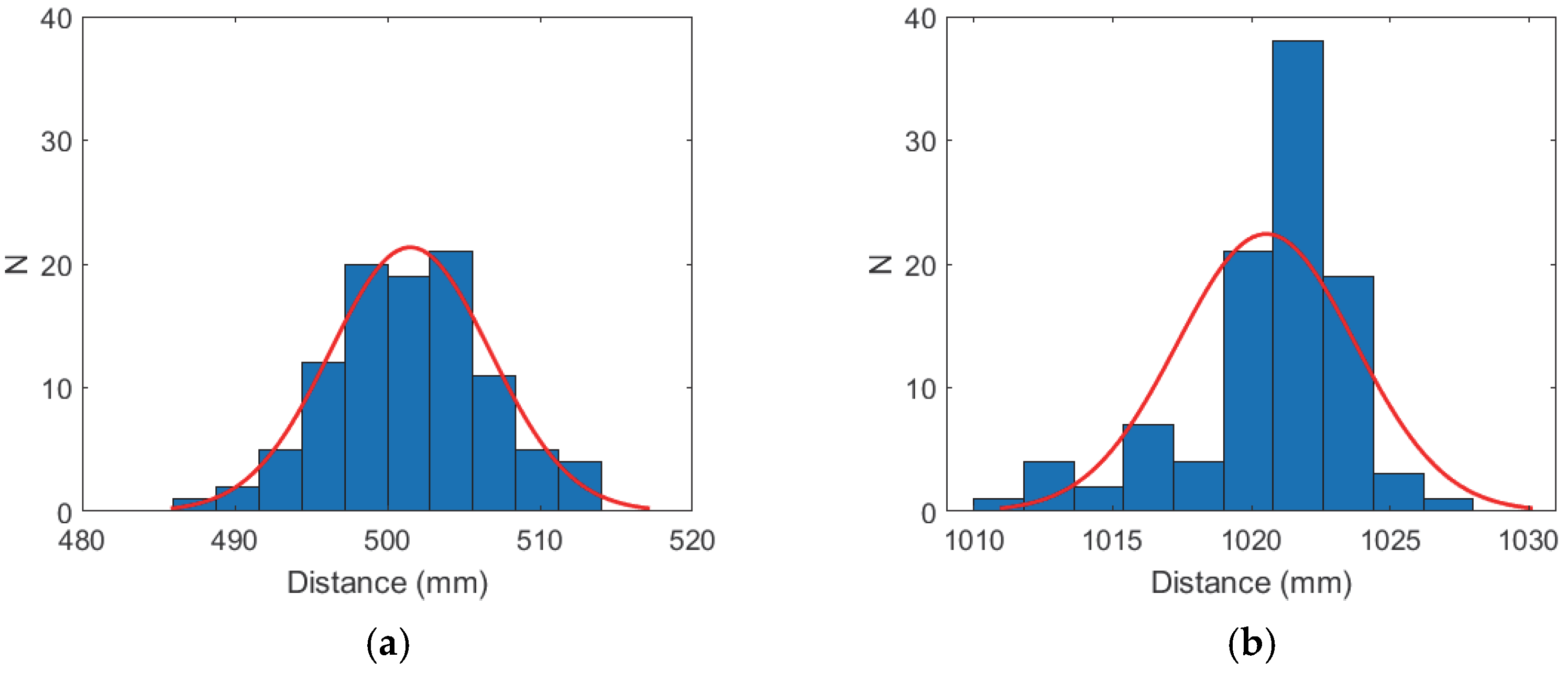
| #1a (50 cm) | 51.98 cm (6.6°) | 0.02 cm (0.3°) | 49.9 cm (6.5°) | 0.9 cm (0.1°) |
| #1b (100 cm) | 102.41 cm (2.2°) | 0.02 cm (0.3°) | 102.5 cm (2.6°) | 1.1 cm (0.1°) |
Publisher’s Note: MDPI stays neutral with regard to jurisdictional claims in published maps and institutional affiliations. |
© 2022 by the authors. Licensee MDPI, Basel, Switzerland. This article is an open access article distributed under the terms and conditions of the Creative Commons Attribution (CC BY) license (https://creativecommons.org/licenses/by/4.0/).
Share and Cite
Bonaiuto, V.; Zanela, A. Improvement of the Sensor Capability of the NAO Robot by the Integration of a Laser Rangefinder. Appl. Syst. Innov. 2022, 5, 105. https://doi.org/10.3390/asi5060105
Bonaiuto V, Zanela A. Improvement of the Sensor Capability of the NAO Robot by the Integration of a Laser Rangefinder. Applied System Innovation. 2022; 5(6):105. https://doi.org/10.3390/asi5060105
Chicago/Turabian StyleBonaiuto, Vincenzo, and Andrea Zanela. 2022. "Improvement of the Sensor Capability of the NAO Robot by the Integration of a Laser Rangefinder" Applied System Innovation 5, no. 6: 105. https://doi.org/10.3390/asi5060105