Review

Nanofluid Structural Forces Alter Solid Wetting, Enhancing Oil Recovery

Department of Chemical and Biological Engineering, Illinois Institute of Technology, Chicago, IL 60616, USA
*
Authors to whom correspondence should be addressed.
Colloids Interfaces 2022, 6(2), 33; https://doi.org/10.3390/colloids6020033
Submission received: 28 April 2022 / Revised: 21 May 2022 / Accepted: 22 May 2022 / Published: 25 May 2022

Abstract

:
Nanofluids have attracted significant research interest for their promising application in enhanced oil recovery. One striking feature leading to the outstanding efficiency of nanofluids in enhanced oil recovery is the structure of nanoparticles, which induces oscillatory structural forces in the confined space between fluid–fluid interfaces or air–liquid and liquid–solid interfaces. To promote the understanding of the oscillatory structural forces and their application in enhanced oil recovery, we reviewed the origin and theory of the oscillatory structural forces, factors affecting their magnitude, and the experimental techniques demonstrating their impacts on enhanced oil recovery. We also reviewed the methods, where the benefits of nanofluids in enhanced oil recovery provided by the oscillatory structural forces are directly manifested. The oscillatory structural forces promote the wetting and spreading of nanofluids on solid surfaces, which ultimately enhances the separation of oil from the reservoir. Some imbibition tests demonstrated as much as 50% increased oil recovery, compared to the cases where the oscillatory structural forces were absent.

1. Introduction

In recent years, the use of nanoparticles in upstream oil production has become increasingly popular [1,2]. In addition to their use in drilling and completion, production and flow assurance, and reservoir sensing, nanoparticles have found a promising use in enhanced oil recovery—mainly as wettability-alteration agents and foam-stabilization agents.
One encouraging application of nanoparticles in enhanced oil recovery is to promote oil displacement from reservoir rock surfaces to enhance oil recovery. The most popular mechanism is wettability alteration, which is the process of altering reservoir rock surface from oil-wet to intermediate-wet or water-wet for easier displacement of oil from the reservoir [3]. Numerous articles have reported the high efficiency of nanoparticles in wettability alteration [3]. Some researchers have adopted the wettability alteration mechanisms of surfactants to explain the wettability alteration using nanoparticles. For example, Alzobaidi et al. [4] explained that cationic nanoparticles alter the wettability by desorbing the anionic organics from the carbonate surface, by adsorbing them onto their surface—an analogue to the ion-pair mechanism for cationic surfactants proposed by Salehi [5]. The anionic nanoparticles alter the carbonate’s wettability by competing with the anionic organics for the positively charged adsorption sites on the carbonate surface. The wettability alteration mechanism for nonionic nanoparticles is classified as hydrogen bonding [6], and the van der Waals interaction takes place with the carbonate surface as well as organic acids. While these mechanistic understandings to some extents have theoretical and experimental grounds, one important wettability alteration mechanism using nanoparticles is often missing or not properly understood: the oscillatory structural forces resulting from the nanoparticles’ self-layering under the confinement of the fluid–fluid and fluid–solid interfaces. For an aqueous phase displacing oil from a solid surface, there will be a confined wedge film between the three-phase contact region when the water-phase contact angle is small. It is a well-known phenomenon that under confinement, nanoparticles self-organize into an ordered and layered structure [7], which gives rise to an oscillatory structural pressure normal to the fluid–fluid interface. The oscillatory structural pressure is higher at the vertex of a confined wedge film than that close to the bulk meniscus (see Figure 1). This oscillatory structural pressure gradient notably strengthens the wetting and spreading of nanofluids [7], facilitating the removal of oil from solid substrates [8].
Another important challenge in foam-enhanced oil recovery is foam stability under reservoir conditions, for which nanoparticles are very efficient, via either the Pickering emulsion mechanism with partially hydrophobic nanoparticle adsorption at the interface [9], or confinement-induced stabilization with hydrophilic nanoparticles crowding in the foam’s lamella [10]. Nanoparticles stabilizing foams via the Pickering emulsion mechanism have been studied in detail [11]. A brief summary of the Pickering emulsion mechanism is that the irreversibly adsorbed, partially hydrophobic nanoparticles at the interface increase the surface pressure and enhance the viscoelasticity of the interface [12]. The increased viscoelasticity is beneficial for slowing the liquid drainage in the foam’s lamella and film rupture. Moreover, based on the Gibbs criteria, once the dilational modulus is larger than half the interfacial tension, the coarsening of the foam bubbles will be effectively arrested [13]. Hydrophilic nanoparticles can also stabilize the foam, albeit in a very different scenario and via a different mechanism. Although hydrophilic nanoparticles do not meaningfully adsorb at the interface, their presence in the foam’s lamella (which is a confined space) leads to the self-layering of the nanoparticles, producing an oscillatory structural pressure retarding the thinning of the foam’s lamella [14].
Recently, there have been articles on the theory and application of the oscillatory structural forces, but there is no comprehensive review of the nature of the oscillatory structural forces, techniques quantifying them, or methods demonstrating their benefits in practical applications—particularly in enhanced oil recovery. Therefore, this work pinpoints the remarkable role of the oscillatory structural forces in enhanced oil recovery using hydrophilic nanoparticles, via wettability alteration by means of enhanced spreading of the nanofluid and foam stabilization. After illustrating the origins of the oscillatory structural forces, the affecting factors are discussed in detail. In addition to the theory on the oscillatory structural forces, this work reviews the experimental techniques demonstrating them. Most importantly, the techniques visualizing the benefit of hydrophilic nanoparticles in enhanced oil recovery are presented. This work provides an overview of the theory and techniques behind utilizing the oscillatory structural forces caused by nanoparticle self-layering under confinement in enhanced oil recovery. The presented theory and techniques guide the application and optimization of the nanofluids with hydrophilic nanoparticles for the maximum benefit in enhanced oil recovery.

2. Theory of the Oscillatory Structural Forces

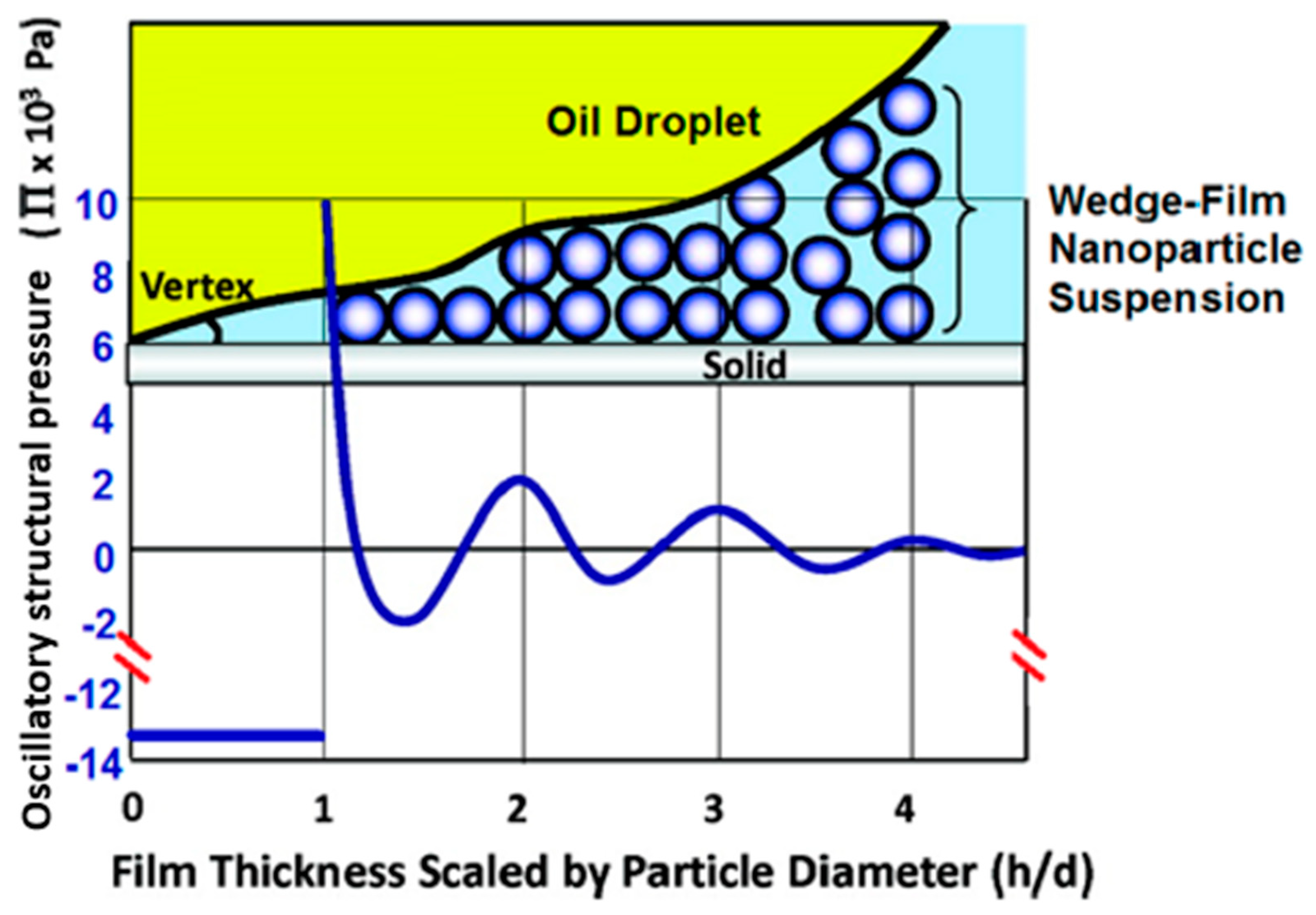
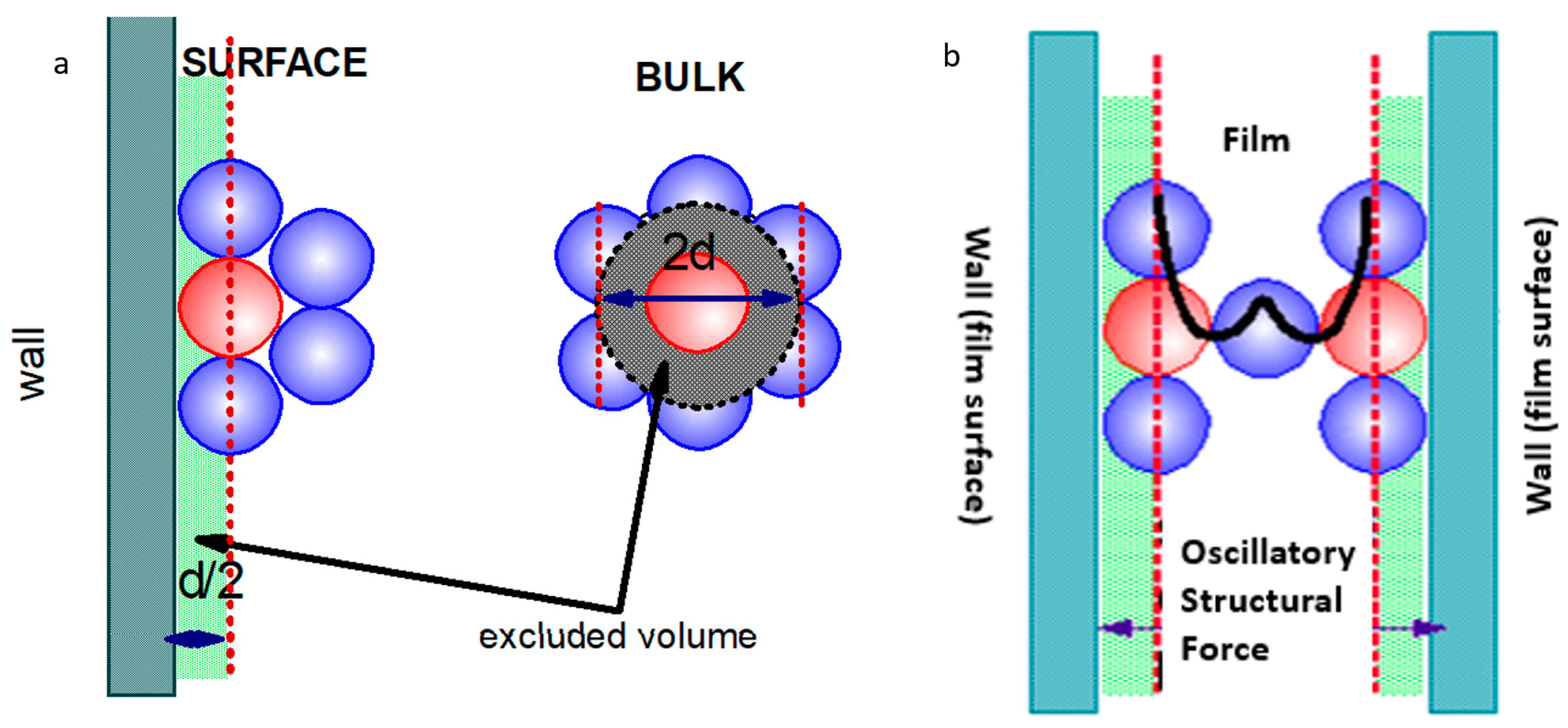
2.1. Origin of the Oscillatory Structural Pressure

The oscillatory structural pressure originates from the difference between the excluded volume of the particles in the bulk and of those at the vicinity of the surface of a smooth solid wall, as illustrated in Figure 2. Assuming that the particles have a uniform diameter of d and volume of v p , the excluded volume around each particle in the bulk is 8 v p . In the fluid with a volume of V , the total free volume V F is given by V F = V ( 1 8 v p n ) , with n being the numerical concentration of the particles. In an elementary volume d V , the free volume is d V F = d V ( 1 8 v p n ) . The possibility of finding a particle in any space in the bulk is W b = d   V F V = d V V ( 1 8 v p n ) . Similarly, the possibility of finding a particle at the wall surface is W w = d V V ( 1 4 v p n ) . Since the ratio of the two possibilities W w W b = 1 4 v p n 1 8 v p n > 1 , the possibility of finding a particle near the wall is greater than that in the bulk. In other words, the density of particles close to the wall surface is greater than that in the bulk.
The same phenomenon exists in many colloidal systems close to the interfaces (air–liquid, liquid–liquid, liquid–solid, or air–solid)—the particles have a greater density than in the bulk. When two surfaces approach one another, the excluded volume effect becomes more significant. As a consequence, particles confined between two interfaces self-organize into an ordered structure (Figure 2b) compared to the random packing in the bulk, similar to the pure liquid molecules confined between two walls [15]. When the degree of confinement is sufficient (i.e., the distance between the two confining surfaces is small enough), the nanoparticles even form an in-layer structure [16]. The local density of the nanoparticles oscillates with the distance from the surface, resulting in an oscillatory structural pressure exponentially decaying with distance between the two confining surfaces.

2.2. Theoretical Calculation of the Oscillatory Structural Pressure

2.2.1. Analytical Expressions Derived from the Radial Distribution Function

Trokhymchuk et al. [17] developed an analytical solution for the oscillatory structural pressure based on the radial distribution function for two large, hard spheres with diameter 2R, dispersed in a fluid of the smaller hard spheres with diameter d. For the cases d << 2R, the surface of the two large spheres can be approximated as two parallel flat surfaces from the view of the small spheres. The scenario is thus useful in simulating the oscillatory structural disjoining pressure resulting from the confinement of particles between two flat surfaces. Under this condition, with the help of the Ornstein–Zernike relation for the direct and total correlation functions, the macroparticle radial distribution function can be calculated [18,19] with an exact expression derived from statistical mechanics [20]. Limiting the calculations to the Percus–Yevick (PY) theory for correlation functions, and using the Laplace transformation, the simple equations for the film interaction energy W s t ( h ) and the oscillatory structural pressure s t ( h ) , as a function of the particle effective volume fraction ϕ , particle effective diameter d e , and film thickness h , are derived as follows:
s t ( h ) = 0 cos ( ω h + φ 1 ) exp ( κ h ) + 1 exp [ δ ( h d e ) ] for   h d e
s t ( h ) = P ¯ for   0 < h < d e
W s t ( h ) = W 0 cos ( ω h + φ 1 ) exp ( κ h ) + W 1 exp [ δ ( h d e ) ] or   h d e
W s t ( h ) = P ¯ ( d e h ) 2 σ ¯   for   0 < h < d e
In Equations (1) and (2), 0 , 1 , W 0 , W 1 , ω , φ 1 , κ , and δ are parameters depending on the nanoparticle volume fraction ϕ. P ¯ is the bulk osmotic pressure estimated by the Carnahan–Starling equation [21]. Trokhymchuk et al. [17] provided the expression and numerical coefficients, estimating their values using cubic polynomial fitting. The film interaction energy W s t ( h ) and the oscillatory structural pressure s t ( h ) were calculated with a known diameter of the nanoparticles and the volume fraction of the nanoparticles using Equations (1) and (2). Figure 3 illustrates the magnitude and oscillatory nature of the oscillatory structural pressure at different film thicknesses estimated using the analytical solution in Equation (1).
Under strong confinement, where nanoparticles are only allowed to form one or two layers, the nanoparticle forms an in-layer structure [16]. However, the analytical method overlooks the impact of the in-layer structure on the film energy and the oscillatory structural pressure. Other than the overlooked in-layer structure, the analytical approaches by Trokhymchuk et al. [17] estimated the osmotic pressure using the Carnahan–Starling equation, which may not be applicable to structured fluids.

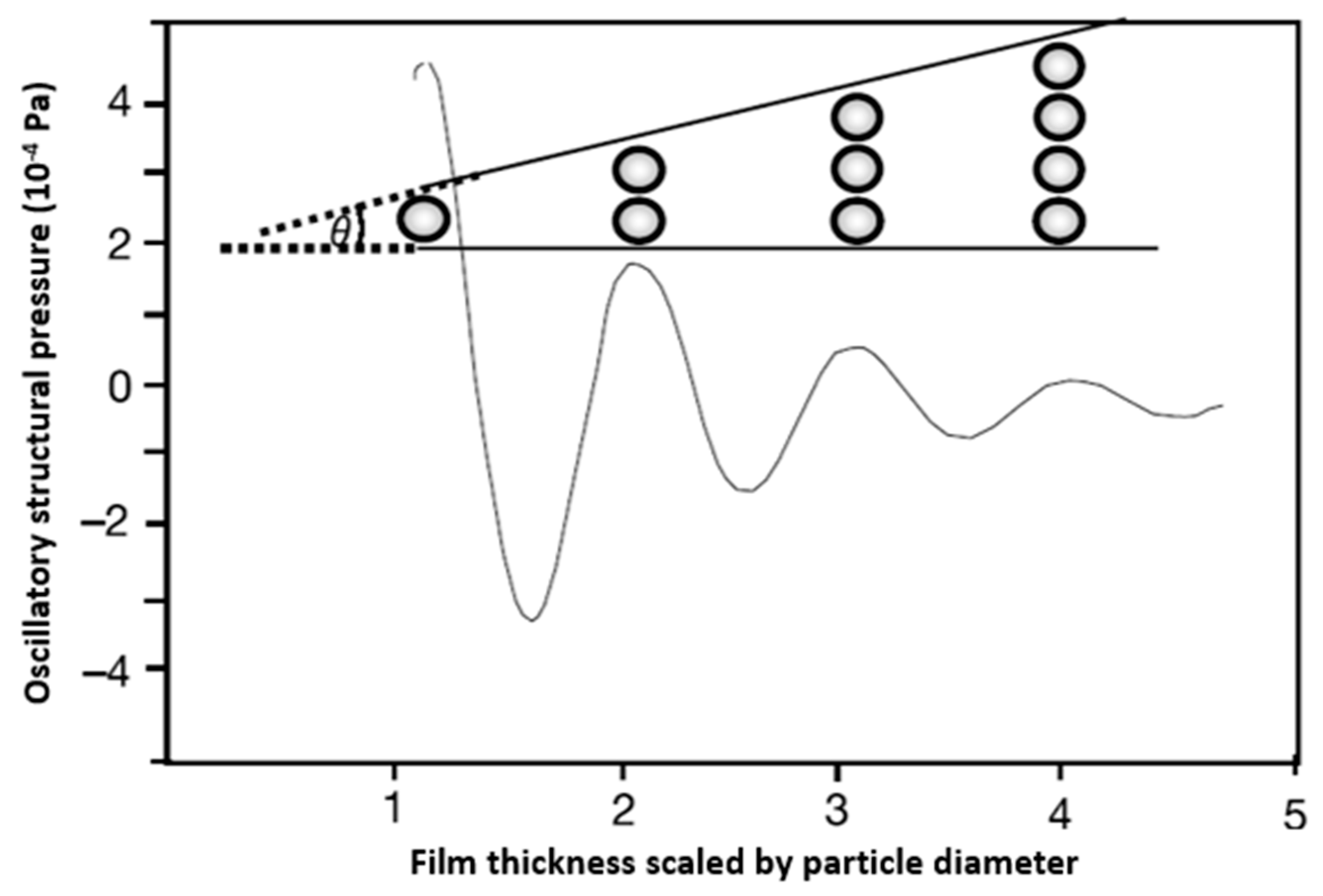
2.2.2. Contact Angle Approach

The approach of using the measured macroscopic contact angle to estimate the film interaction energy and the oscillatory structural pressure dates back to the work of Bangham and Razouk [22], who considered the effect of an adsorbed Langmuir monolayer in contact with the main meniscus on the macroscopic contact angle θ e q of a droplet sitting on an ideal solid. They proposed the following relationship for the free energy W s / g of the solid–vapor interface and equilibrium contact angle θ e q :
W s / g = R T p = 0 p g Γ d ln p + γ g / l cos θ e q
where p g is the vapor saturation pressure of the liquid at the experimental temperature T , Γ is the adsorption per unit area, γ g / l is the liquid surface tension, and R is the gas constant. With the contribution of the liquid film on the solid in contact with the droplet, Frumkin [23], Derjagun [24], De Gennes [25], and Churaev [26] later proposed a model that could be used to explain the role of the surface forces in wetting and spreading. These authors proposed the following relationship for the contact angle and the film free surface energy:
γ g / l cos θ e q = γ g / l + h 0 h ( h ) d h + P γ h e q
where the integral takes into consideration the effect of the liquid free film energy on the solid, and the third term is the energy of the liquid meniscus on the solid at an equilibrium film thickness h e q with a capillary pressure P γ .  ( h ) is the film’s disjoining pressure isotherm, and the film’s stability is governed by the criteria P γ = ( h ) and d ( h ) d h > 0 . Equation (4) can be simplified into Equation (3) in the limiting case of monomolecular adsorption on a solid surface. Equation (4) for the film free energy does not take into consideration the molecular 2D self-layering in the wetting film confined between the solid–fluid and fluid–fluid interfaces in the contact region.
We proposed Equation (5) [27] to calculate the free nanofilm energy, taking into consideration the fact that the nanofilm has a multilayered structure, and applied the osmotic pressure to calculate the nanofilm free energy [28]:
W s t = h P o s m f i l m ( h ) d h + P γ h e q = A cos ( 2 π h d ) exp ( h d ) = γ ( cos θ e q 1 )
where P o s m f i l m is the osmotic pressure in the nanofluid film and γ is the interfacial tension between the two fluids. The term A cos ( 2 π h d ) exp ( h d ) considers the oscillatory decay nature of the nanofilm free energy W s t with the increasing film thickness h , scaled by the particle diameter d . The amplitude A of the oscillatory decay is an energy-scaling parameter with the definition of the structural stabilization barrier of the equilibrium nanofilm with the corresponding equilibrium three-phase macroscopic contact angle θ e q . Since the in-layer nanofilm on a solid is usually stable [10], the amplitude A is calculated using the measured equilibrium three-phase macroscopic contact angle at a known number of particle layers. With an estimated A , Equation (5) allows for the calculation of the film energy as well as the oscillatory structural pressure and the prediction of the values of the macroscopic three-phase contact angle of the nanofilm with different numbers of layers. The details of using this approach to estimate the film energy and oscillatory structural pressure with the measured equilibrium contact angle are presented in our previous work [27,29].
Equation (5) shows that the film–meniscus contact angle is directly related to the film energy. The thinner the film, the greater the film energy, and the larger the contact angle. This correlation between the film thickness, film energy, and contact angle has been verified experimentally by measuring the film–meniscus profile and film thickness under differential interferometry in reflected light [30]. The advantage of the contact angle approach is that the film energy estimated from the experimentally measured contact angle automatically considers the contribution of the in-layer structure [16] and the film size [31].

2.2.3. Relationship between the Film Energy and the Oscillatory Structural Pressure

The film energy W s t ( h ) and oscillatory structural pressure s t ( h ) are given by the following equation [7,30]:
W s t ( h ) = h e s t ( h ) d h  
A simple derivative calculation of d W s t ( h ) / d h from Equation (6) gives the expression of the oscillatory structural pressure s t ( h ) as a function of the film thickness h :
s t ( h ) = A exp ( h d ) [ 2 π d sin ( 2 π h d ) 1 d cos ( 2 π h d ) ]
Equation (5) indicates that the minimum of the film’s structural interaction energy always corresponds to a film thickness of an integral number of particle layers. Therefore, only films with a thickness of an integral number of layers are stable or metastable. Equations (6) and (7) show that the minimum of the film’s structural interaction energy indicates the maximum oscillatory structural pressure. At the vertex of the confined wedge film, the film is thinnest, with a minimum in the film’s structural interaction energy and a maximum in the oscillatory structural pressure. As the film’s thickness increases layer by layer in the wedge film toward the bulk, the magnitude of the film interaction energy minima and oscillatory structural pressure maxima diminishes. As a result, there is a pressure gradient pointing from the bulk to the vertex, as shown in Figure 1, which drives the spreading of the nanofluid toward the vertex. The enhanced spreading of the nanofluid on a solid surface facilitates the separation of oil from the reservoir surface.

2.3. Factors Affecting the Oscillatory Structural Pressure

2.3.1. Effect of the Nanoparticle Volume Fraction

The effect of the nanoparticle volume fraction on the oscillatory structural pressure is straightforward. With a higher nanoparticle volume fraction, the nanoparticle structuring phenomenon under confinement is more pronounced [16]. Consequently, both the oscillatory structural pressure and the film energy have a greater amplitude with increasing effective nanoparticle volume fraction [17]. Trokhymchuk et al. [17] showed that the magnitude of the oscillatory structural pressure increased almost 10-fold as the volume fraction jumped from 0.15 to 0.31. For the same degree of confinement, the higher the volume fraction, the larger the oscillatory structural pressure. Therefore, it is often reported that a higher nanoparticle concentration helps the oil recovery.

2.3.2. Effect of Nanoparticle Diameter and Polydispersity

For a fixed volume fraction, the smaller the nanoparticle diameter, the greater the number of nanoparticles. Thus, more particles are expected to be crowded in the confined space between the interfaces. As discussed above, the magnitude of both the film energy and the oscillatory structural pressure is proportional to the osmotic pressure of the nanofluid. Since the osmotic pressure increases with a greater density of the particles, the nanofluid with a fixed nanoparticle volume fraction and smaller nanoparticles always has a greater magnitude of the oscillatory structural pressure and film energy. Based on the theoretical analysis of Trokhymchuk et al. [17] discussed above, the oscillatory structural pressure and film energy isotherms are inversely proportional to the cube of the effective particle diameter at a fixed effective nanoparticle volume fraction.
Polydispersity affects the ordered packing of the nanoparticles under confinement. A high polydispersity index of the nanoparticles can disrupt their layering, reducing the magnitude of the film energy and the oscillatory structural pressure. In practical applications such as enhanced oil recovery, it is desirable to keep the polydispersity index of the nanoparticles as low as possible, so as to maximize the benefit of the oscillatory structural pressure from the nanoparticles’ self-organization under confinement.

2.3.3. Effect of the Interfacial Tension and Three-Phase Contact Angle

The capillary force, defined by the interfacial tension and the three-phase contact angle, along with the hydrostatic force, dominates the shape of the fluid–fluid interface and, thus, largely determines the degree of confinement. A lower interfacial tension and smaller contact angle often result in a stronger confinement with a greater magnitude of the oscillatory structural pressure and film energy. For this reason, lower interfacial tension and contact angle usually benefit the performance of nanofluids in wetting and spreading and, therefore, in enhanced oil recovery.

2.3.4. Effect of Film Size

In the analytical solution of the oscillatory structural pressure, the film size was not considered. It was found experimentally that the film’s size has a significant impact on its thickness and stepwise thinning [31,32]. The smaller the film, the more stable the film size. When reducing the film size, the thickness of the nanofilm can increase to one more particle layer—that is, the reverse stepwise thickening of the film under compression. This phenomenon is explained by the dark spot expansion mechanism during film thinning [33]. The smaller the film, the lower the possibility of a vacancy (dark spot) appearing to trigger the film thinning. The vacancy (dark spot) also disrupts the self-organization of the nanoparticles, reducing the magnitude of the film interaction energy and oscillatory structural pressure. It is therefore reasonable to infer that a smaller film leads to a smaller oscillatory structural pressure.

3. Experiments Demonstrating the Oscillatory Structural Pressure

In this section, we briefly review the different techniques demonstrating the effect of oscillatory structural pressure on different applications.

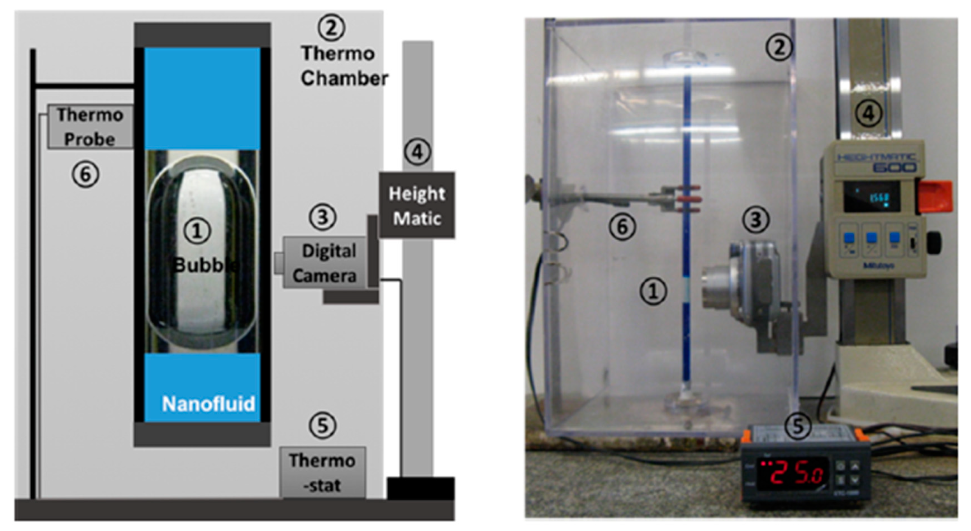
3.1. Moving Bubble Inside a Vertical Circular Tube

For an air bubble immersed in a nanofluid inside a vertical circular tube, there is a nanofluid film between the air and the solid tube wall. The thickness of the nanofluid film can be tuned by the ratio of bubble length L to the tube diameter D. Under the confinement of the air–liquid and liquid–solid surfaces, the nanoparticles self-layer into an ordered structure. Depending on the thickness of the nanofluid film, the degree of confinement is different, as is the oscillatory structural pressure. Consequently, the nanofluid film undergoes a stepwise change in viscosity as the film thickness changes stepwise, with each step equal to the effective diameter of the nanoparticles. The stepwise change in the viscosity leads to the stepwise change in the bubbles’ rising velocity, which can be monitored using the setup in Figure 4 [34].
The bubbles’ rising velocity at a capillary number smaller than 10−6, with a common fluid and a silica nanofluid with the same bulk viscosity, is presented in Figure 5. The bubbles’ rising velocity in a nanofluid is 100 times slower than that in a common liquid, due to the increased film viscosity as a result of the self-organization of the nanoparticles. With a small increase in the bubble length, the bubble velocity increases in a stepwise manner in a nanofluid. The same phenomenon was observed for bubbles rising in a silica nanofluid [34] and in a micellar nanofluid [35]. The much slower rising velocity in a stepwise manner was attributed to the oscillatory structural pressure in the nanofluid film confined between the rising bubbles and the tube wall. This phenomenon shows that the nanoparticles do form an ordered and layered structure under the confinement of air–aqueous and aqueous–solid interfaces. For an oil–aqueous–solid three-phase system in oil recovery, nanoparticles in the aqueous nanofluid film confined between the oil and the solid surface are expected to form a layered structure, which helps separate the oil from the solid substrate.

3.2. Stepwise Film Thinning under Reflected-Light Interferometry

One well-known phenomenon caused by the oscillatory structural forces is the stepwise film thinning for a free suspension nanofluid film [31,36,37,38,39,40,41]. During the film thinning driven by capillarity, and under the confinement of the film surfaces, the nanoparticles in the nanofluid self-organize in multiple ordered layers. Reflected-light interferometry is a very useful tool to monitor the stepwise film thinning, as the film displays different colors at different thicknesses under monochromatic reflected light [32,42]. We note that optical knowledge of the light reflection and interference from the film surfaces, microscope objective numerical aperture, and optical depth resolution is required to correctly interpret the film images for data analysis to estimate the film thickness during the stepwise film thinning.
The setup of the reflected-light interferometry to monitor the stepwise film thinning caused by the oscillatory structural forces, along with the foam film’s stepwise thinning interferogram, is presented in Figure 6. More information about the film’s formation and observation can be found in the literature [38,39,40,41,42].
The curved nanofluid film also undergoes stepwise thinning via the same mechanism as the flat nanofluid film. The stepwise thinning of the curved nanofluid film has more practical importance than that of the flat film, as it assimilates the foam or emulsion film thinning related to the stability of foams and emulsions. Nikolov and Wasan [32] applied reflected-light interferometry to investigate the stepwise thinning of the curved film, dominated by the capillary pressure, film area on the micellar curved film, and the oscillatory structural force. A sketch of the optical arrangement to study the stepwise thinning of the curved nanofluid film of an air bubble attached to a nanofluid is presented in Figure 7.
Reflected-light interferometry is a very powerful tool for monitoring the foam film’s thinning, which offers insight on the foam’s stability, since this is governed by the stability of the foam film. Whether it is the foam film or nanofluid film on the solid surface in contact with the oil, the nature of the nanoparticle layering and the oscillatory structural forces are the same. Therefore, the stepwise thinning of the nanofluid’s foam film is also able to reveal the potential of the nanofluid in altering the wettability of the solid substrate for oil recovery.

3.3. Atomic Force Microscopy (AFM) for the Measurement of the Oscillatory Structural Force

Several research groups have applied AFM to directly measure the oscillatory structural forces between two surfaces [45,46,47,48,49]. Richetti et al. [45] measured the forces as different separations between two cetyltrimethylammonium bromide (CTAB)-coated mica surfaces immersed in CTAB micellar solutions. Zeng et al. [48] used colloidal probe AFM (as shown in Figure 8) to measure the forces of a silica nanofluid film confined between the probe and a silicon wafer surface. While AFM is able to confirm the oscillatory decay nature of the oscillatory structural forces in both cases, by nature, it is difficult for the AFM method to precisely locate the minima and maxima of the oscillatory structural pressure. Since an external force is exerted to push the colloidal probe toward the flat solid substrate, the magnitude of the oscillatory structural forces resulting from the self-organization of the nanoparticles is difficult to correctly determine. The last layer of the nanoparticles between the colloidal probe and the flat solid substrate cannot be repelled [49]. AFM is also not able to reveal the information on the stability of the nanofluid film, the stepwise thinning of the nanofluid film, or the timescale for the layer-to-layer transitions.

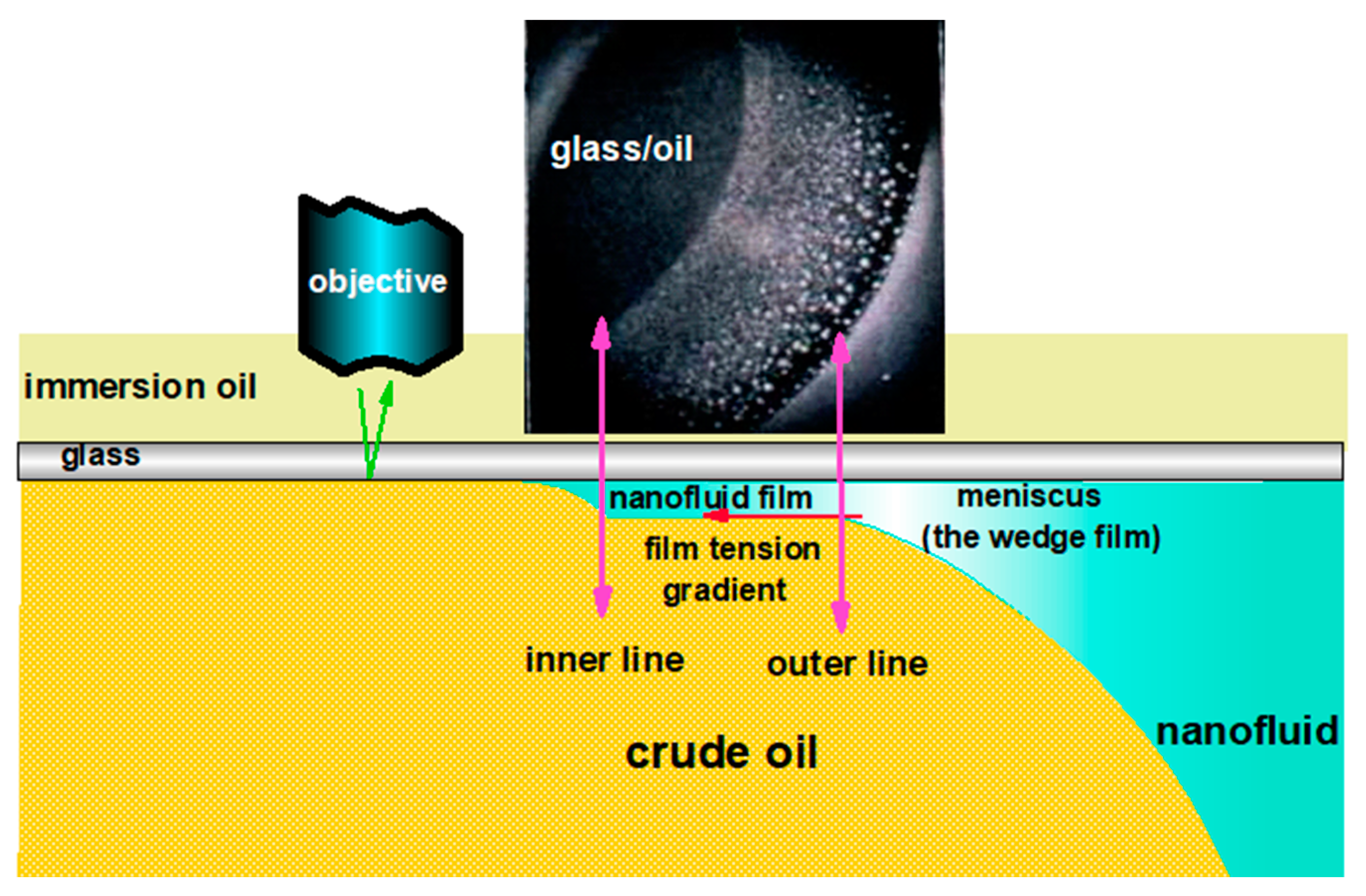
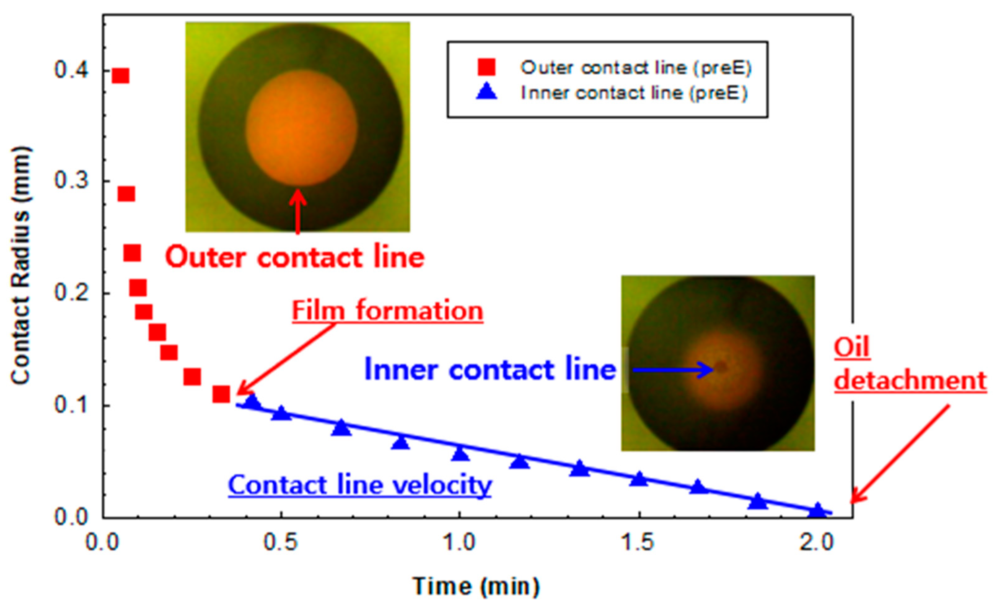
3.4. Nanofluid Displacing an Oil Droplet on a Solid Surface under Reflected-Light Interferometry

Reflected-light interferometry can also be used in a scenario closely related to the practical application of the nanofluid in surface cleaning and enhanced oil recovery [50,51]. For a glass substrate immersed in a nanofluid with an oil droplet pre-deposit on the lower surface, the movement of the oil–nanofluid–solid three-phase contact line can be observed through the upper surface of the glass via reflected-light interferometry, as shown in Figure 9. A detailed experimental setup can be found in our previous works [50,51]. Initially, the oil droplet shrinks under the capillary force and hydrostatic force, with a moving contact line that we call the “outer contact line”. After the capillary force and hydrostatic force reach equilibrium, the outer contact line stops moving, and an inner contact line appears due to the formation and spreading of the nanofluid film between the glass surface and the oil droplet. As the inner contact line moves toward the center of the oil droplet, the nanofluid film gradually separates the oil from the glass surface, and eventually displaces the oil from the glass. The dynamics of the movement of the outer and inner contact lines for a polymeric nanofluid displacing oil from glass substrate, captured via reflected-light interferometry, are shown in Figure 10. For the common fluid without nanoparticles, there is no inner contact line, and the oil droplet does not detach from the solid substrate. The dynamics of the inner contact line and the oil droplet’s removal from the solid substrate are directly related to the efficiency of the nanofluid in displacing oil from the reservoir.

4. Experiments Visualizing the Effects of a Nanofluid in Enhanced Oil Recovery

As shown in Figure 10, for the water-phase contact angle, at the oil–nanofluid–solid three-phase contact region, there is a wedge film where the nanoparticles self-organize into an ordered and layered structure, which gives rise to the oscillatory structural forces. The oscillatory structural forces promote the spreading of the nanofluid on the solid surface, and bring tremendous benefit to enhanced oil recovery using a nanofluid. In our lab, we applied several experimental techniques demonstrating the benefits of the oscillatory structural forces in enhanced oil recovery.

4.1. Oil Displacement in a 2D Glass Pore

In a simple experiment, a 2D glass pore was made by sticking plain microscopic glass covers together with a small separation using two strong magnets to simulate the porous oil reservoir, allowing for the easy observation of the process of oil displacement. The strength of the magnets was varied to maintain the pore gap between 0.5 and 3 μm. The area of the plain microscopic glass covers was 2 cm2. As shown in Figure 11, two 2D glass pores filled with crude oil were vertically placed in two identical plastic cuvettes. The amount of crude oil trapped in the 2D pore was 0.3–0.4 mL. A microemulsion additive (commercially available as MA-844 from CESI Chemical) diluted in DI water at a 1:5 mass ratio and an NSF additive (proprietary nanofluid) with the same interfacial tension as crude oil were simultaneously added into the left-hand and right-hand cuvettes, respectively. For the microemulsion additive, there was only the capillary force and hydrostatic force, which were not efficient in displacing the hexadecane out of the 2D glass pore. However, for the right-hand cuvette with the nanofluid, in addition to the capillary and hydrostatic forces, there were oscillatory structural forces induced by the nanofluid in the confined space. The oscillatory structural forces are powerful in displacing oil, as can be seen in the video in Supplementary Materials. The dynamics of crude oil removal plotted in Figure 12 demonstrate that the crude oil displacement is much faster and significantly greater in extent than that with the normal fluid with no oscillatory structural force.

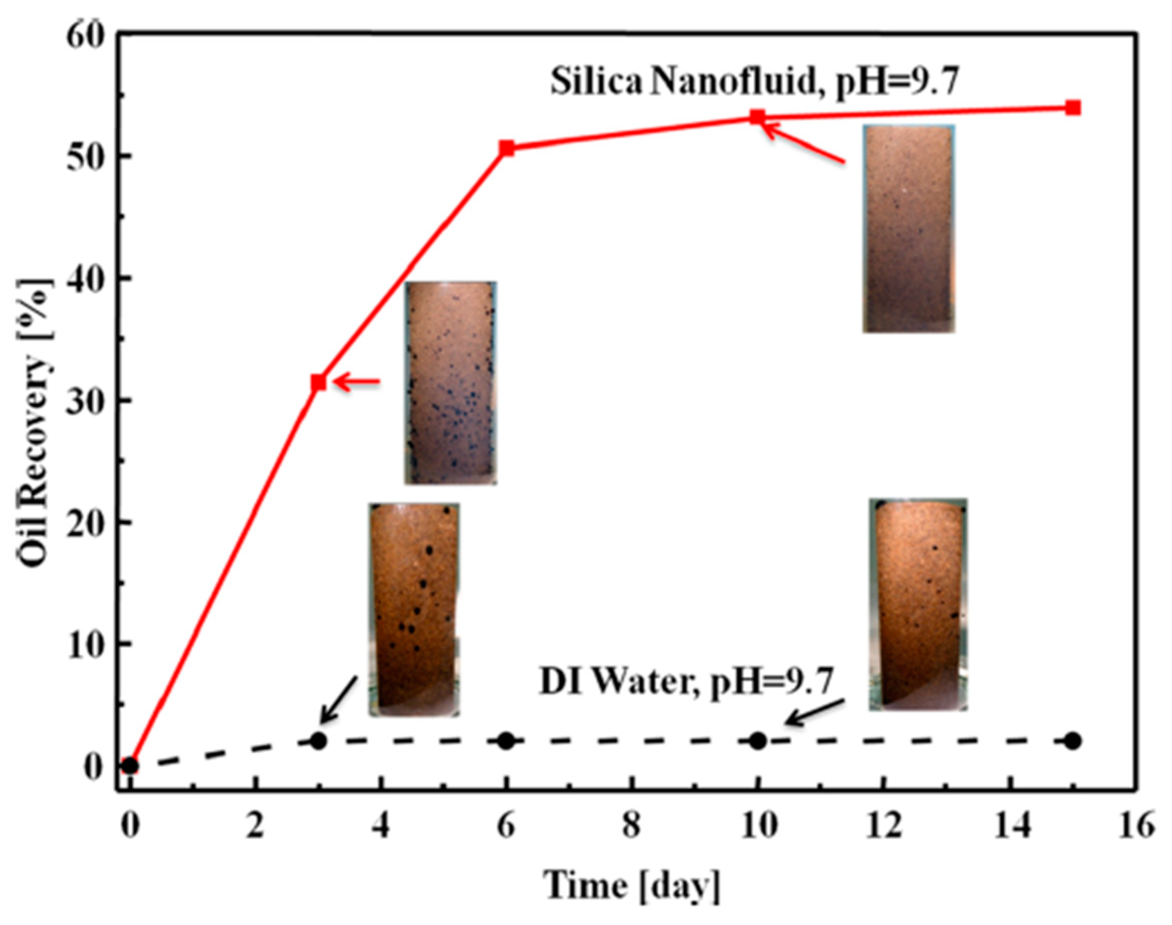
4.2. Imbibition of the Nanofluid into a Crude-Oil-Pre-Saturated Sandstone Core

Imbibition is a popular test revealing the efficiency of different reagents in enhanced oil recovery [52], and can also be applied to demonstrate the role of the oscillatory structural forces in enhanced oil recovery. The setup is similar to that shown in Figure 11, with the use of a core similar to that in the oil reservoir and crude oil. In one set of tests, the patented nanofluid from [8] was used. Figure 13 shows the outstanding efficiency of nanofluids in enhanced oil recovery (50% more oil recovery) which, again, is contributed to by the oscillatory structural pressure.

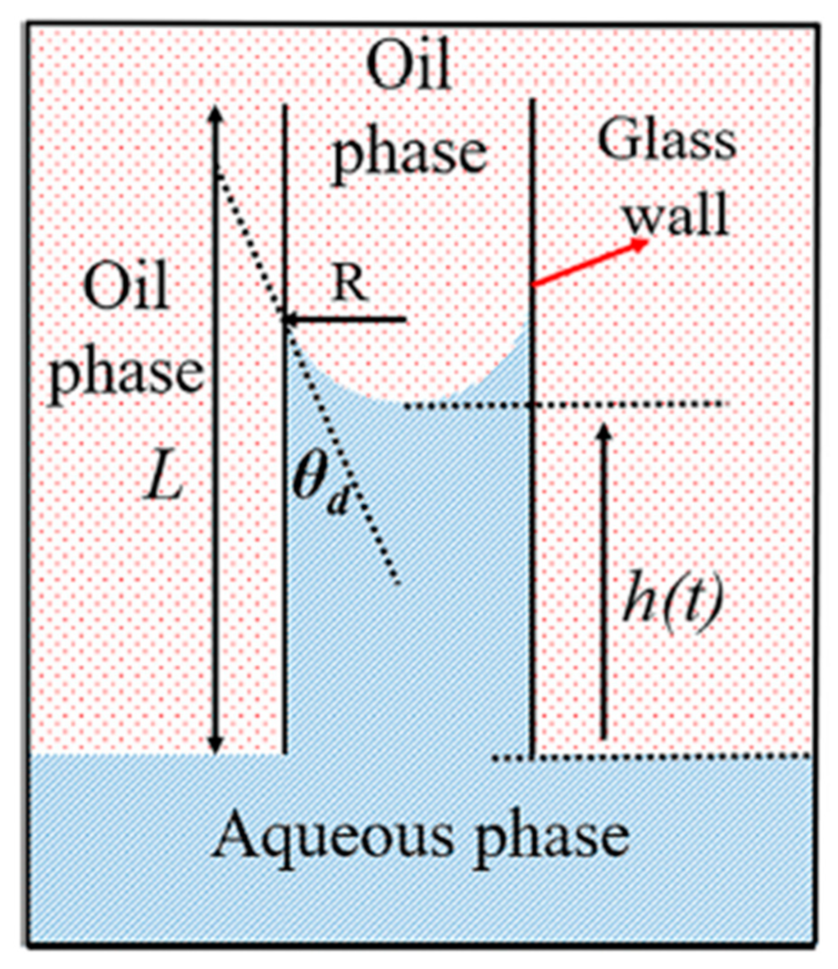
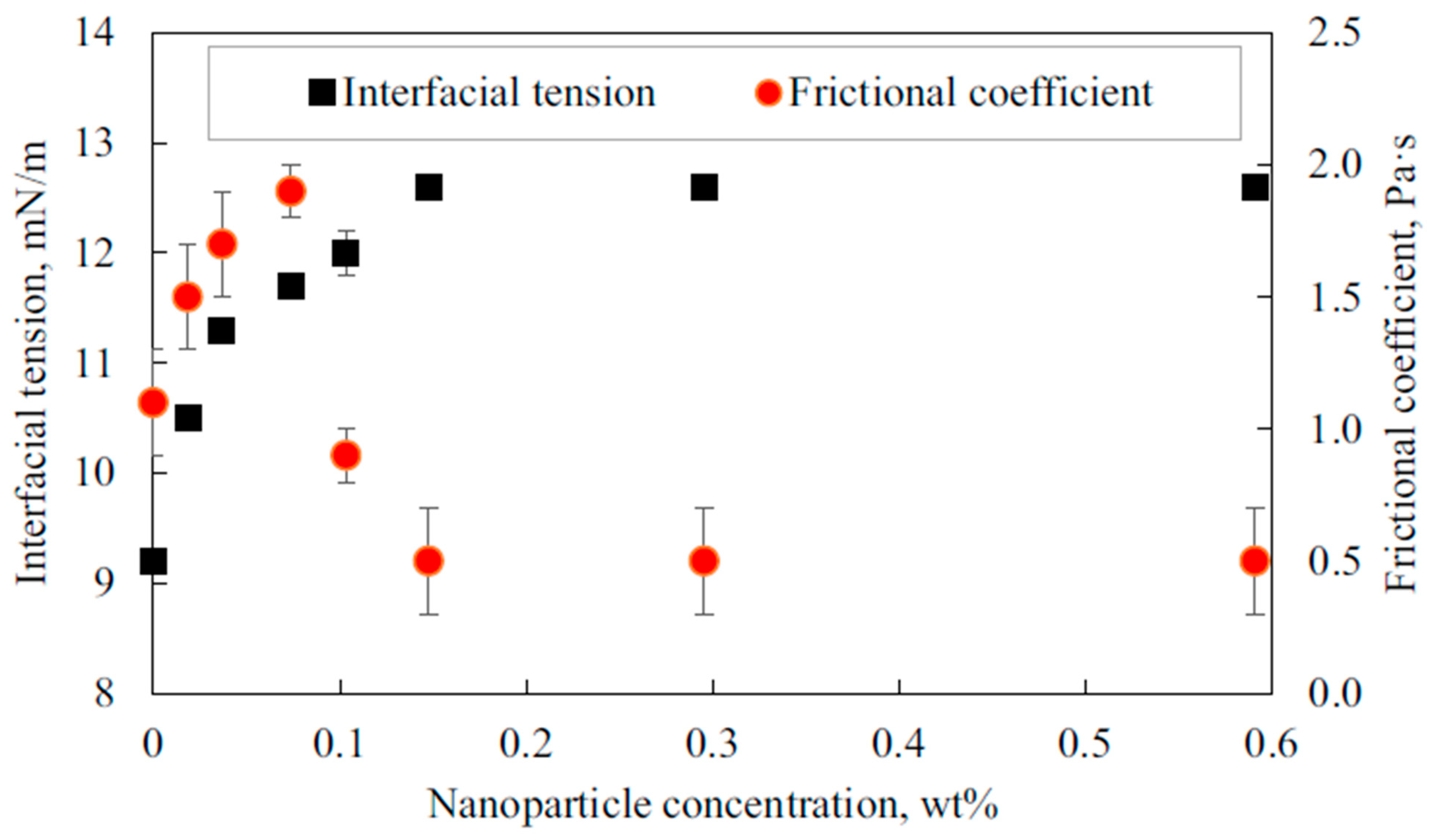
4.3. Nanofluids Displacing Oil in a Single Capillary

The benefit of the oscillatory structural forces in enhanced oil recovery can also be manifested by the dynamics of the nanofluid displacing oil in a vertically placed capillary. Using the setup shown in Figure 14, Wu et al. [53] analyzed the dynamics of a common fluid and a nanofluid in displacing oil based on the augmented Lucas–Washburn equation considering the buoyant force, the viscous force in the displaced oil phase, and the contact line friction. It was found that the nanofluid reduced the frictional coefficient at the three-phase contact region by as much as fourfold, as shown in Figure 15. The contributing factor was the oscillatory structural force, as semi-quantitatively explained by the estimated oscillatory structural forces and the theory of contact line friction [54,55,56].

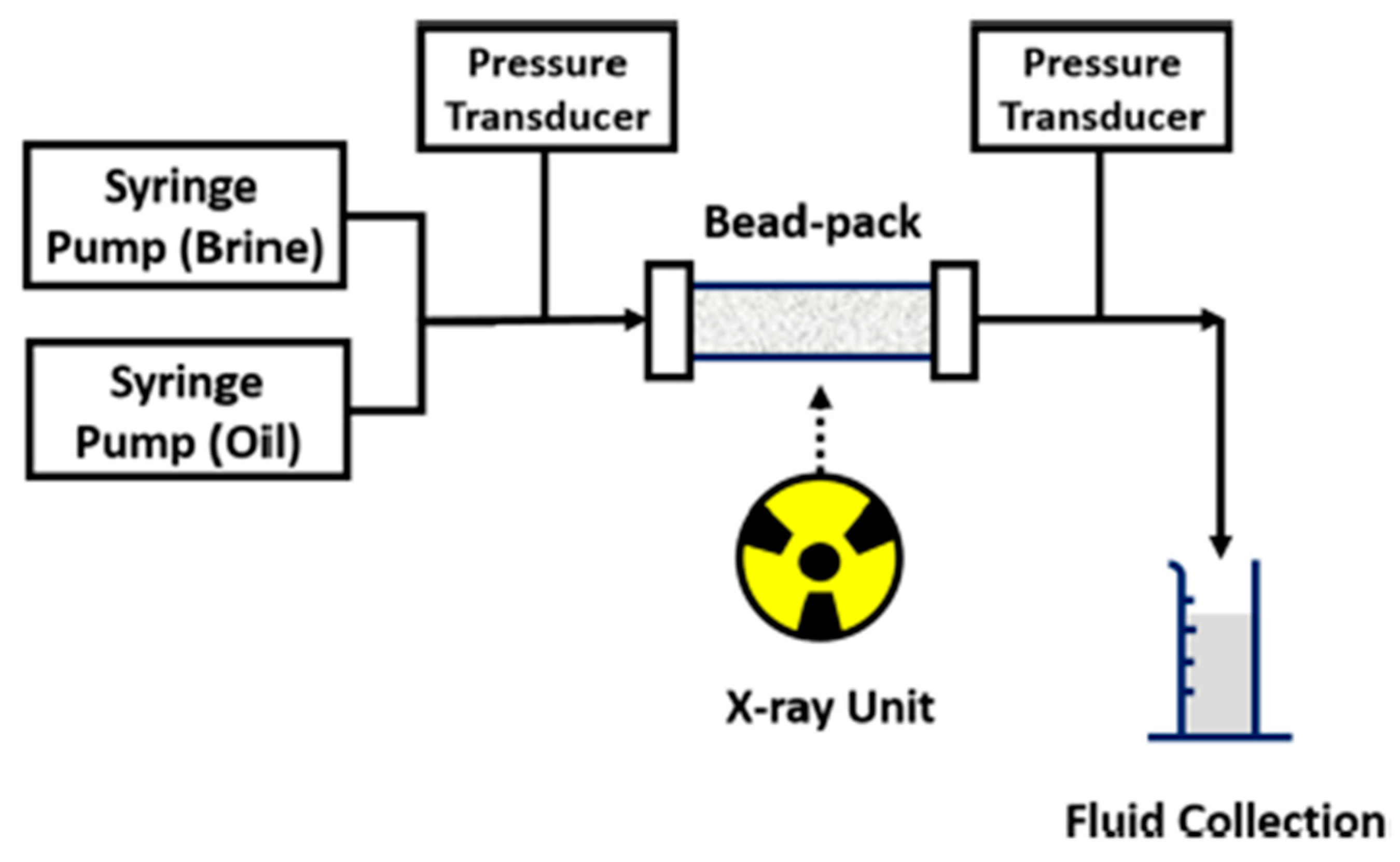
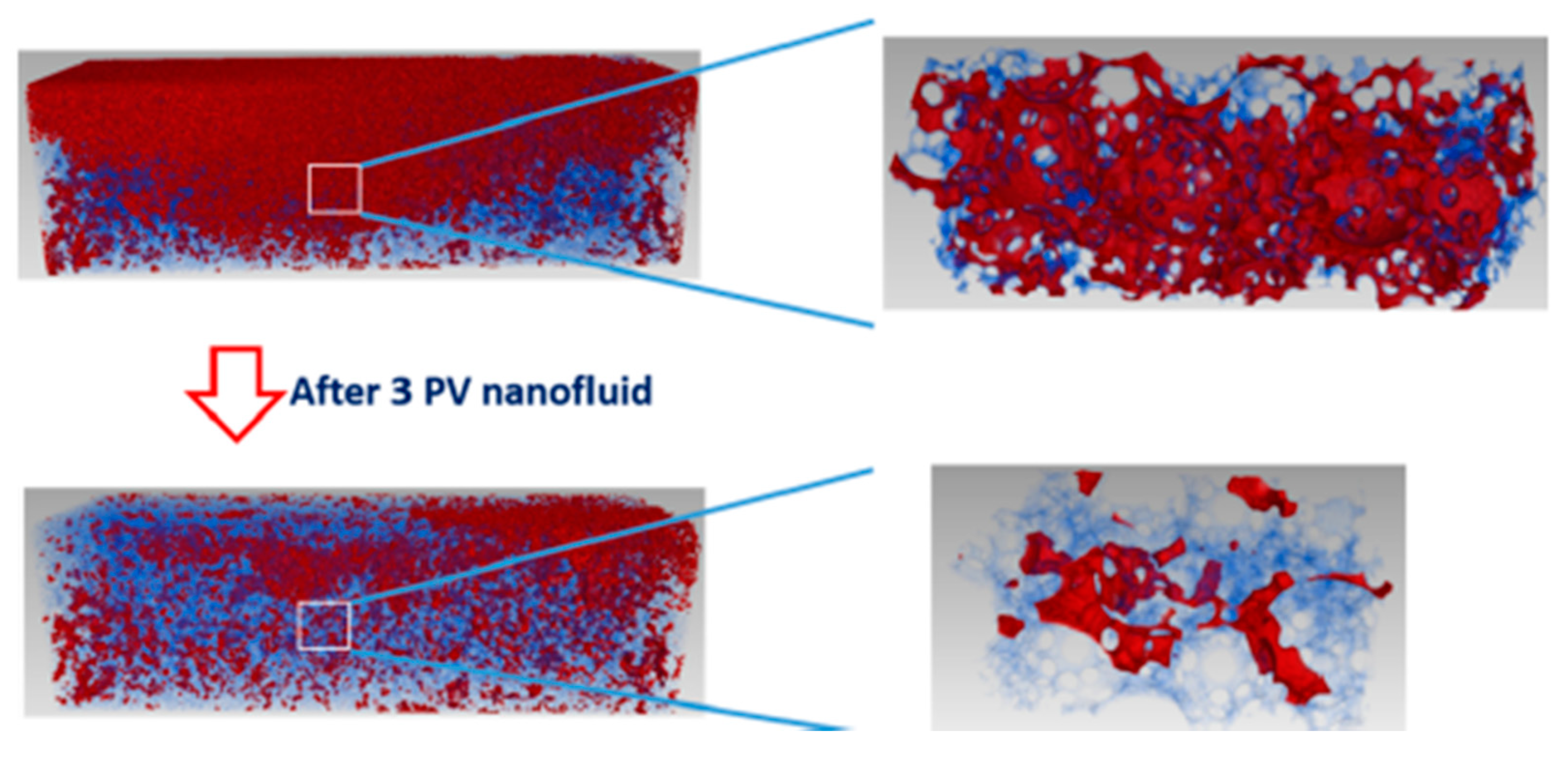
4.4. Microvisualization of Nanofluid Flooding Displacing Oil from a Bead Pack Using X-ray Microtomography

Zhang et al. [57,58] used high-resolution X-ray microtomography (X-ray micro-CT) to visualize the removal of oil from a bead pack via brine and nanofluid flooding. The experimental setup using X-ray micro-CT to visualize brine and nanofluid flooding on the oil in the bead pack is shown in Figure 16. More details can be found in [57,58].
From the distribution of the oil before and after the nanofluid flooding shown in Figure 17, it is clear that the oscillatory structural forces with the nanofluid bring significant benefit to the enhanced oil recovery. After three pore volumes of brine flooding, the porous bead pack was filled with a significant amount of oil, with large clusters of oil blobs. After continuously flooding the bead pack with three pore volumes of nanofluid flooding, much more oil was displaced out of the bead pack, with only small and disconnected oil blobs. The cumulative oil recovery showed an additional 16.8% oil recovery as a result of the nanofluid flooding. Jha et al. [59] used a similar high-resolution microvisualization technique, and also demonstrated the contribution of the oscillatory structural forces for a nanofluid displacing oil from a porous medium.
For better visualization, Zhang et al. used sintered glass beads and a model oil as a model system. In coreflooding close to reservoir conditions, it was difficult to observe the displacement of the oil from the cores. However, by measuring the incremental oil recovery during coreflooding, many researchers have reported the tremendous benefit of nanofluids in enhanced oil recovery, attributing the improvement to the oscillatory structural forces as the additional driving force [60,61,62].

5. Conclusions

Under confinement between two interfaces, hydrophilic nanoparticles self-organize into an ordered and layered structure, which induces the oscillatory structural forces originating from the fluctuation in the density of the particles close to the confining surfaces. The value of the oscillatory structural forces can be estimated using either the analytical solution derived from the Ornstein–Zernike equation or the contact-angle approach with a measured equilibrium contact angle at a known film thickness. Because of the unknown fitting parameters and the approximation in the analytical approach, the contact-angle approach is the preferred method for estimating the oscillatory structural pressure, as it is based on the experimentally measured contact angle. Key features of and major experimental findings relating to the oscillatory structural forces are as follows:
  • Nanoparticle self-layering under confinement and the performance of oscillatory structural forces depend on the nanoparticle volume fraction, diameter, polydispersity, interfacial tension, contact angle, and film size. The higher the nanoparticle volume fraction, the smaller the nanoparticles’ size, polydispersity, interfacial tension, and contact angle, and the greater the oscillatory structural force.
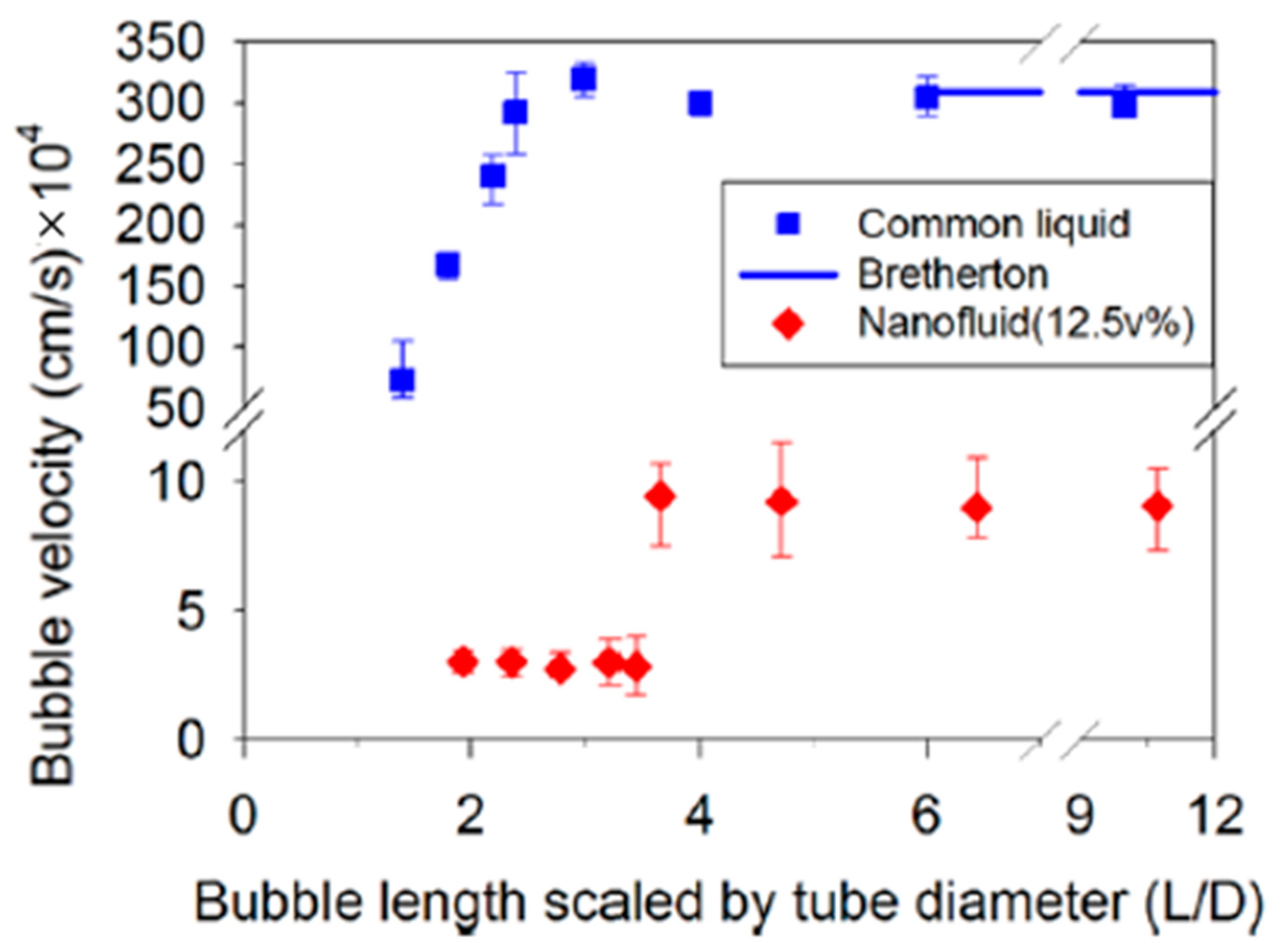
  • Bubbles rising in a nanofluid in a tube reveal the nanoparticle layering and structuring in the confined nanofluid film. The oscillatory structural forces increase the viscosity of the nanofluid film.
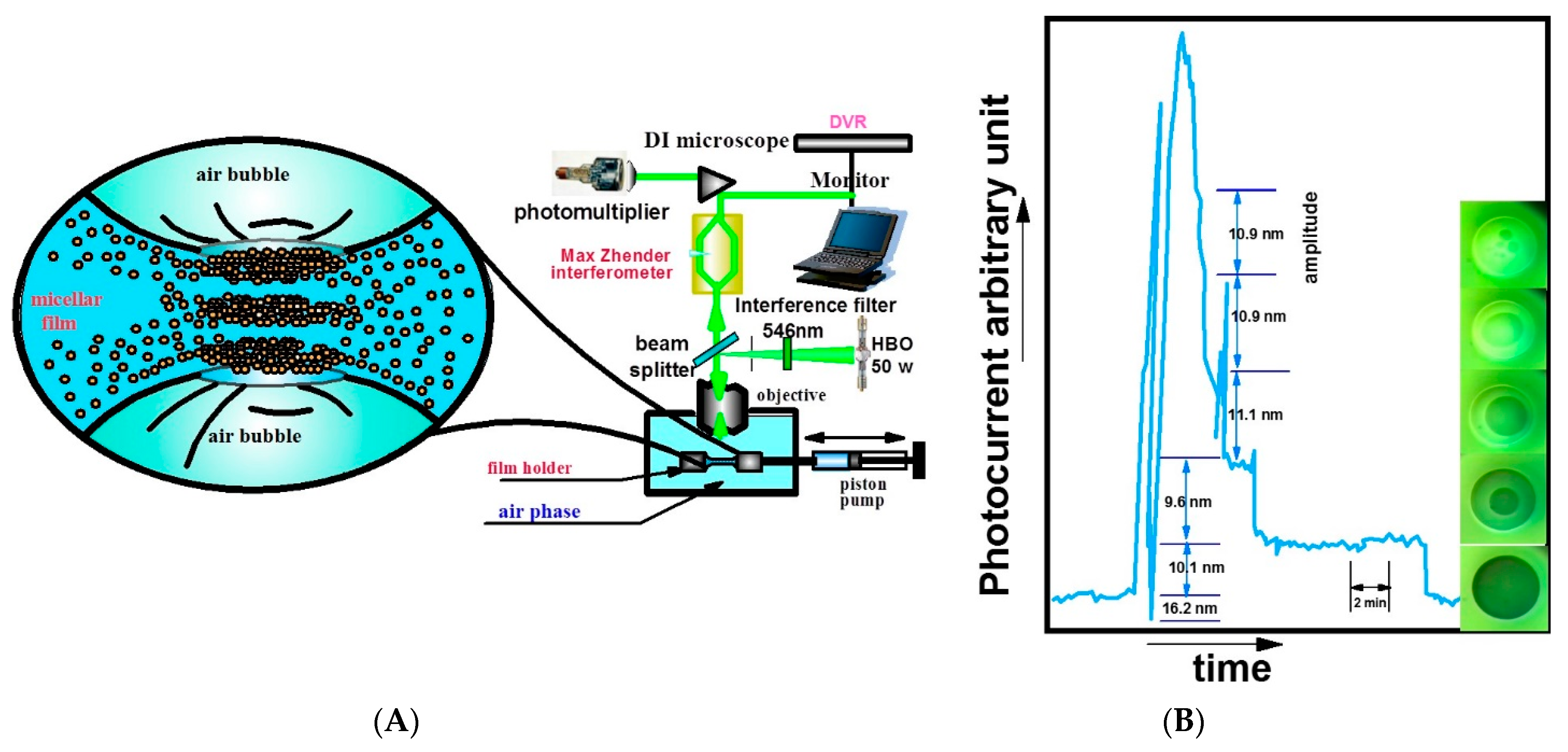
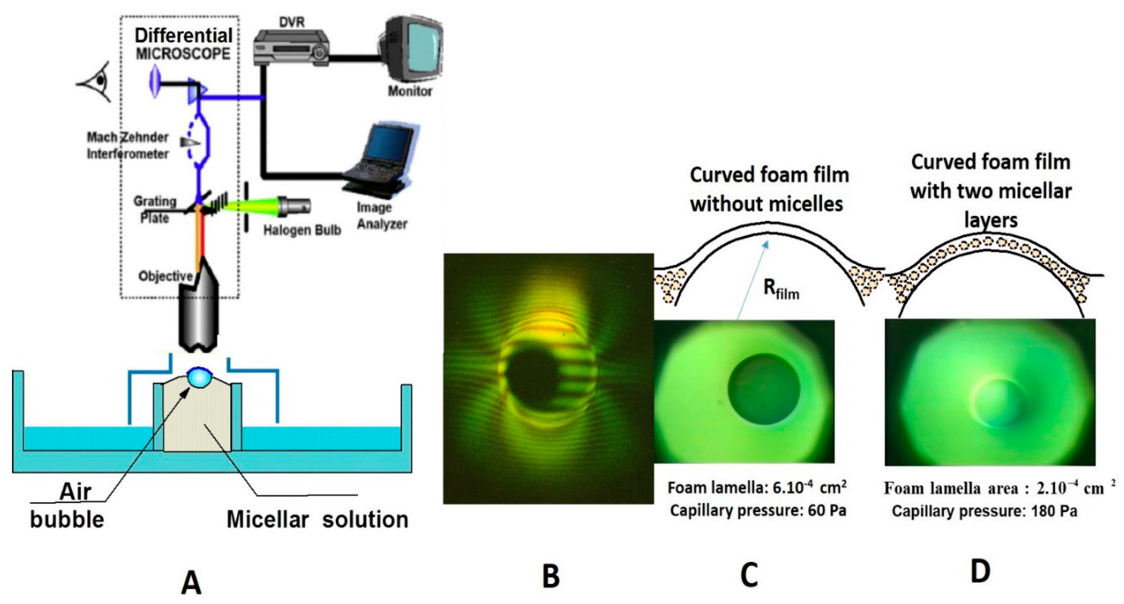
  • The stepwise thinning of the nanofilm observed under reflected-light interferometry is an informative experiment evidencing the nanoparticles’ layering in the confined nanofluid film.
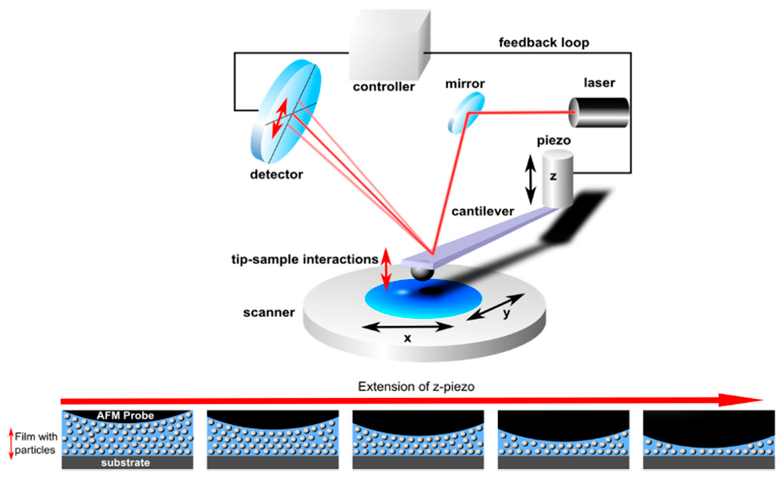
  • The oscillatory decay nature of the oscillatory structural pressure is directly evidenced by the AFM measurement of the forces between two surfaces surrounded by a nanofluid. However, since in AFM measurements the nanofluid film is thinned under external force, this method offers limited information on the stability of the nanofluid film, mechanism, and dynamics of the nanofluid film’s stepwise thinning.
  • The nanofluid displacing the oil droplet on a solid surface under reflected-light interferometry shows the enhanced nanofluid spreading and wetting on solid surfaces caused by the oscillatory structural forces.
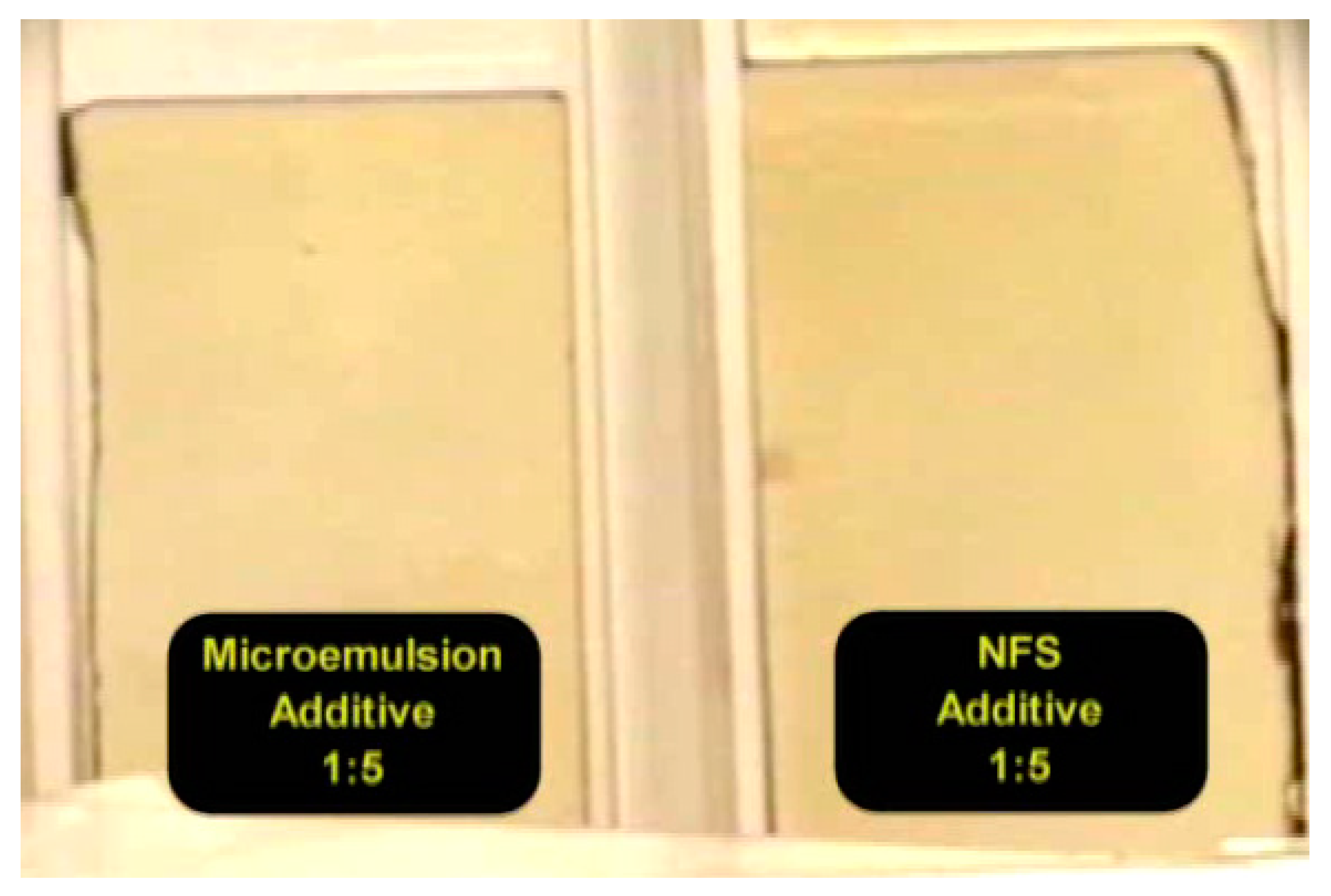
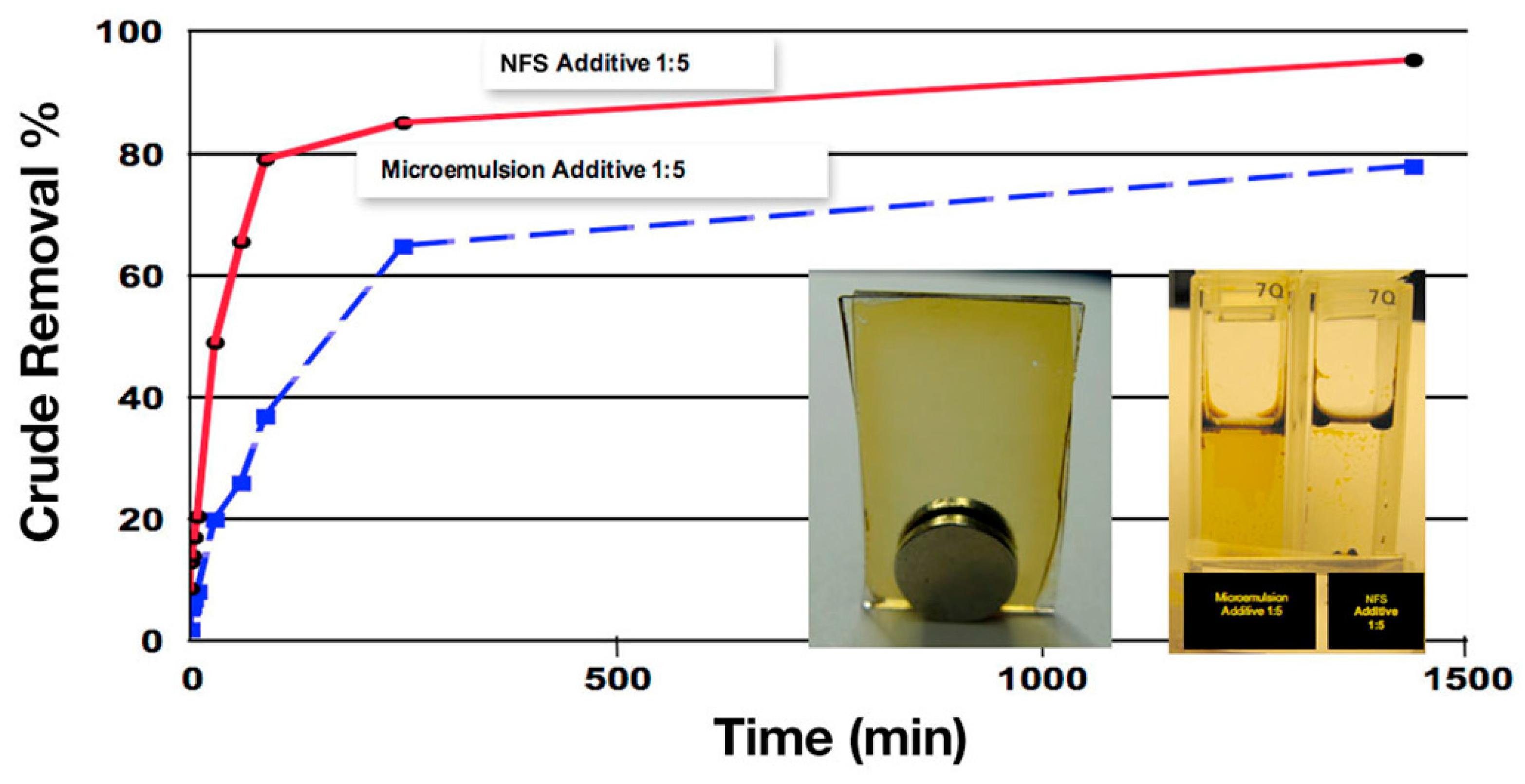
  • The imbibition tests in 2D glass pores, cores, and flooding, as well as on a nanofluid displacing oil in a single capillary, all imply the immense benefit of nanofluids in enhanced oil recovery as a result of the oscillatory structural forces.
More research is needed to complete the theory of the oscillatory structural forces. For example, the nanoparticles’ collective interaction through the radial distribution function (RDF) needs more attention to promote the understanding of nanoparticle structuring under confinement, and the resulting oscillatory structural forces. The RDF may also shed light on how the particles’ shape, size, and effective volume fraction affect the oscillatory structural pressure and, eventually, enhance the nanofluid’s wetting of the solid. It is also important to know how the properties of the solid surface and the electrolyte impact the oscillatory structural forces.
There is still room to uncover the nature of the oscillatory structural forces. The reported theoretical and experimental studies summarized and reviewed in this work should be helpful for researchers in the oil industry to design efficient nanofluids to boost oil production efficiency.

Supplementary Materials

The following supporting information can be downloaded at: https://www.mdpi.com/article/10.3390/colloids6020033/s1: A video recording the dynamics of the crude oil displacement from a 2D glass pore by a nanofluid and a by microemulsion with no nanoparticles (or micelles). The beginning of the video shows the optical setup. Two 2D glass pores filled with crude oil are placed in two cuvettes with transparent glass walls. A CCD camera is used to record the crude oil displacement. At around 30 s in the video, the microemulsion and the nanofluid aqueous solutions are added separately into the two cuvettes until the 2D glass pores are completely submerged in the solution. Immediately after the submersion, the aqueous solutions start to invade the 2D glass pores to displace the crude oil. The invasion of the nanofluid into the 2D glass pores is much faster than that of the microemulsion, as seen from the position of the aqueous front. With the nanofluid, the crude oil film quickly shrinks to form oil droplets, which float to the top under the buoyant force. The sharp comparison of the remaining crude oil film in the 2D glass pores after 5, 30, 60, 90, 120, 150, 180, and 210 min under the actions of the microemulsion and nanofluid demonstrates the outstanding efficiency of the nanofluid in displacing crude oil from the solid substrate.

Author Contributions

Writing—review and editing, P.W., A.D.N., D.T.W. All authors have read and agreed to the published version of the manuscript.

Funding

This research received no external funding.

Institutional Review Board Statement

Not applicable.

Informed Consent Statement

Not applicable.

Data Availability Statement

Not applicable.

Acknowledgments

The authors are thankful to Noah H. Cho and Hua Zhang for their research contributions illustrating the role of the oscillatory structural forces in the practical application of nanofluids for wetting of solids and enhanced oil recovery.

Conflicts of Interest

The authors declare no conflict of interest.

References

  1. Nassar, N.N.; Cortés, F.B.; Franco, C.A. Nanoparticles: An Emerging Technology for Oil Production and Processing Applications; Springer: Cham, Germany, 2021. [Google Scholar]
  2. Cheraghian, G.; Rostami, S.; Afrand, M. Nanotechnology in enhanced oil recovery. Processes 2020, 8, 1073. [Google Scholar] [CrossRef]
  3. Mohammed, M.; Babadagli, T. Wettability alteration: A comprehensive review of materials/methods and testing the selected ones on heavy-oil containing oil-wet systems. Adv. Colloid Interface Sci. 2015, 220, 54–77. [Google Scholar] [CrossRef] [PubMed]
  4. Alzobaidi, S.; Wu, P.K.; Da, C.; Zhang, X.; Hackbarth, J.; Angeles, T.; Rabat-Torki, N.J.; MacAuliffe, S.; Panja, S.; Johnston, K.P. Effect of surface chemistry of silica nanoparticles on contact angle of oil on calcite surfaces in concentrated brine with divalent ions. J. Colloid Interface Sci. 2021, 581, 656–668. [Google Scholar] [CrossRef] [PubMed]
  5. Salehi, M.; Johnson, S.J.; Liang, J.-T. Mechanistic study of wettability alteration using surfactants with applications in naturally fractured reservoirs. Langmuir 2008, 24, 14099–14107. [Google Scholar] [CrossRef] [PubMed]
  6. Dehghan Monfared, A.; Ghazanfari, M.H.; Jamialahmadi, M.; Helalizadeh, A. Potential Application of Silica Nanoparticles for Wettability Alteration of Oil–Wet Calcite: A Mechanistic Study. Energy Fuels 2016, 30, 3947–3961. [Google Scholar] [CrossRef]
  7. Wasan, D.T.; Nikolov, A.D. Spreading of nanofluids on solids. Nature 2003, 423, 156–159. [Google Scholar] [CrossRef]
  8. Zhang, H.; Nikolov, A.; Wasan, D. Enhanced oil recovery (EOR) using nanoparticle dispersions: Underlying mechanism and imbibition experiments. Energy Fuels 2014, 28, 3002–3009. [Google Scholar] [CrossRef]
  9. Da, C.; Zhang, X.; Alzobaidi, S.; Hu, D.; Wu, P.; Johnston, K.P. Tuning Surface Chemistry and Ionic Strength to Control Nanoparticle Adsorption and Elastic Dilational Modulus at Air-Brine Interface. Langmuir 2021, 37, 5795–5809. [Google Scholar] [CrossRef]
  10. Wasan, D.; Nikolov, A. Thin liquid films containing micelles or nanoparticles. Curr. Opin. Colloid Interface Sci. 2008, 13, 128–133. [Google Scholar] [CrossRef]
  11. Griffith, C.; Daigle, H. Manipulation of Pickering emulsion rheology using hydrophilically modified silica nanoparticles in brine. J. Colloid Interface Sci. 2018, 509, 132–139. [Google Scholar] [CrossRef]
  12. Alzobaidi, S.; Da, C.; Wu, P.; Zhang, X.; Rabat-Torki, N.J.; Harris, J.M.; Hackbarth, J.E.; Lu, C.; Hu, D.; Johnston, K.P. Tuning Nanoparticle Surface Chemistry and Interfacial Properties for Highly Stable Nitrogen-In-Brine Foams. Langmuir 2021, 37, 5408–5423. [Google Scholar] [CrossRef] [PubMed]
  13. Maestro, A.; Rio, E.; Drenckhan-Andreatta, W.; Langevin, D.; Salonen, A. Foams stabilised by mixtures of nanoparticles and oppositely charged surfactants: Relationship between bubble shrinkage and foam coarsening. Soft Matter 2014, 10, 6975–6983. [Google Scholar] [CrossRef]
  14. Nikolov, A.D.; Wasan, D.T. Micellar films: Thinning and structure. In Encyclopedia of Surface and Colloid Science, 3rd ed.; CRC Press: Boca Raton, FL, USA, 2015; pp. 4297–4312. [Google Scholar]
  15. Israelachvili, J.N. Intermolecular and Surface Forces; Academic Press: Burlington, MA, USA, 2011. [Google Scholar]
  16. Chu, X.; Nikolov, A.; Wasan, D. Monte Carlo simulation of inlayer structure formation in thin liquid films. Langmuir 1994, 10, 4403–4408. [Google Scholar] [CrossRef]
  17. Trokhymchuk, A.; Henderson, D.; Nikolov, A.; Wasan, D.T. A simple calculation of structural and depletion forces for fluids/suspensions confined in a film. Langmuir 2001, 17, 4940–4947. [Google Scholar] [CrossRef]
  18. Henderson, D. An explicit expression for the solvent contribution to the force between colloidal particles using a hard sphere model. J. Colloid Interface Sci. 1988, 121, 486–490. [Google Scholar] [CrossRef]
  19. Attard, P.; Bérard, D.R.; Ursenbach, C.P.; Patey, G.N. Interaction free energy between planar walls in dense fluids: An Ornstein-Zernike approach with results for hard-sphere, Lennard-Jones, and dipolar systems. Phys. Rev. A 1991, 44, 8224. [Google Scholar] [CrossRef] [PubMed]
  20. Hansen, J.-P.; McDonald, I.R. Theory of Simple Liquids: With Applications to Soft Matter; Academic Press: Cambridge, MA, USA, 2013. [Google Scholar]
  21. Carnahan, N.F.; Starling, K.E. Equation of state for nonattracting rigid spheres. J. Chem. Phys. 1969, 51, 635–636. [Google Scholar] [CrossRef]
  22. Bangham, D.; Razouk, R. Adsorption and the wettability of solid surfaces. Trans. Faraday Soc. 1937, 33, 1459–1463. [Google Scholar] [CrossRef]
  23. Frumkin, A. On the wetting phenomena and attachment of bubbles. Zhur. Fiz. Khim. (J. Phys. Chem.) 1938, 12, 337–345. [Google Scholar]
  24. Derjaguin, B. Theory of capillary condensation and related capillary effects. Calculation of spreading action of polymolecular liquid films. Zh. Fiz. Khim 1940, 14, 137. [Google Scholar]
  25. De Gennes, P.-G. Wetting: Statics and dynamics. Rev. Mod. Phys. 1985, 57, 827. [Google Scholar] [CrossRef]
  26. Churaev, N.V.; Sobolev, V.D. Prediction of Contact Angles on the Basis of the Frumkin-Derjaguin Approach. Adv. Colloid Interface Sci. 1995, 61, 1–16. [Google Scholar] [CrossRef]
  27. Nikolov, A.; Wu, P.; Wasan, D. Structure and stability of nanofluid films wetting solids: An overview. Adv. Colloid Interface Sci. 2019, 264, 1–10. [Google Scholar] [CrossRef] [PubMed]
  28. Henderson, D.; Lozada-Cassou, M. A simple theory for the force between spheres immersed in a fluid. J. Colloid Interface Sci. 1986, 114, 180–183. [Google Scholar] [CrossRef]
  29. Nikolov, A.; Wu, P.; Wasan, D. Novel approach for calculating the equilibrium foam nanofilm-meniscus contact angle and the film free energy. J. Colloid Interface Sci. 2019, 557, 591–597. [Google Scholar] [CrossRef]
  30. Nikolov, A.; Kondiparty, K.; Wasan, D. Nanoparticle self-structuring in a nanofluid film spreading on a solid surface. Langmuir 2010, 26, 7665–7670. [Google Scholar] [CrossRef]
  31. Nikolov, A.D.; Wasan, D.T. The foam film’s stepwise thinning phenomenon and role of oscillatory forces. Adv. Colloid Interface Sci. 2022, 303, 102636. [Google Scholar] [CrossRef]
  32. Nikolov, A.; Wasan, D. Effects of film size and micellar polydispersity on film stratification. Colloids Surf. A Physicochem. Eng. Asp. 1997, 128, 243–253. [Google Scholar] [CrossRef]
  33. Kralchevski, P.; Nikolov, A.; Wasan, D.T.; Ivanov, I. Formation and expansion of dark spots in stratifying foam films. Langmuir 1990, 6, 1180–1189. [Google Scholar] [CrossRef]
  34. Cho, H.K.; Nikolov, A.D.; Wasan, D.T. Step-Wise Velocity of an Air Bubble Rising in a Vertical Tube Filled with a Liquid Dispersion of Nanoparticles. Langmuir 2017, 33, 2920–2928. [Google Scholar] [CrossRef]
  35. Cho, N.H.; Nikolov, A.D.; Wasan, D.T. Prediction of the rate of the rise of an air bubble in nanofluids in a vertical tube. J. Colloid Interface Sci. 2018, 525, 115–118. [Google Scholar] [CrossRef] [PubMed]
  36. Lee, J.; Nikolov, A.; Wasan, D. Stepwise thinning dynamics of a foam film formed from an anionic micellar solution. J. Colloid Interface Sci. 2017, 487, 217–222. [Google Scholar] [CrossRef] [PubMed]
  37. Nikolov, A.D.; Wasan, D.T. Effects of surfactant on multiple stepwise coalescence of single drops at liquid-liquid interfaces. Ind. Eng. Chem. Res. 1995, 34, 3653–3661. [Google Scholar] [CrossRef]
  38. Basheva, E.S.; Nikolov, A.D.; Kralchevsky, P.A.; Ivanov, I.B.; Wasan, D.T. Multi-stepwise drainage and viscosity of macroscopic films formed from latex suspensions. In Surfactants in Solution; Springer: New York, NY, USA, 1991; pp. 467–479. [Google Scholar]
  39. Ochoa, C.; Gao, S.; Srivastava, S.; Sharma, V. Foam film stratification studies probe intermicellar interactions. Proc. Natl. Acad. Sci. USA 2021, 118, e2024805118. [Google Scholar] [CrossRef]
  40. Yilixiati, S.; Rafiq, R.; Zhang, Y.; Sharma, V. Influence of salt on supramolecular oscillatory structural forces and stratification in micellar freestanding films. ACS Nano 2018, 12, 1050–1061. [Google Scholar] [CrossRef]
  41. Zhang, Y.; Sharma, V. Nanoridge formation and dynamics of stratification in micellar freestanding films. Langmuir 2018, 34, 1208–1217. [Google Scholar] [CrossRef]
  42. Nikolov, A.; Wasan, D. Ordered micelle structuring in thin films formed from anionic surfactant solutions: I. Experimental. J. Colloid Interface Sci. 1989, 133, 1–12. [Google Scholar] [CrossRef]
  43. Dimitrov, A.S.; Kralchevsky, P.A.; Nikolov, A.D.; Wasan, D.T. Contact angles of thin liquid films: Interferometric determination. Colloids Surf. 1990, 47, 299–321. [Google Scholar] [CrossRef]
  44. Lobo, L.A.; Nikolov, A.; Dimitrov, A.; Kralchevski, P.; Wasan, D.T. Contact angle of air bubbles attached to an air-water surface in foam applications. Langmuir 1990, 6, 995–1001. [Google Scholar] [CrossRef]
  45. Richetti, P.; Kekicheff, P. Direct measurement of depletion and structural forces in a micellar system. Phys. Rev. Lett. 1992, 68, 1951. [Google Scholar] [CrossRef]
  46. Ludwig, M.; von Klitzing, R. Recent progress in measurements of oscillatory forces and liquid properties under confinement. Curr. Opin. Colloid Interface Sci. 2020, 47, 137–152. [Google Scholar] [CrossRef]
  47. Schön, S.; von Klitzing, R. Experimental evaluation of additional short ranged repulsion in structural oscillation forces. Soft Matter 2018, 14, 5383–5392. [Google Scholar] [CrossRef] [PubMed]
  48. Zeng, Y.; Schön, S.; von Klitzing, R. Silica nanoparticle suspensions under confinement of thin liquid films. J. Colloid Interface Sci. 2015, 449, 522–529. [Google Scholar] [CrossRef] [PubMed]
  49. Christov, N.C.; Danov, K.D.; Zeng, Y.; Kralchevsky, P.A.; von Klitzing, R. Oscillatory Structural Forces Due to Nonionic Surfactant Micelles: Data by Colloidal—Probe AFM vs. Theory. Langmuir 2010, 26, 915–923. [Google Scholar] [CrossRef] [PubMed]
  50. Kondiparty, K.; Nikolov, A.D.; Wasan, D.; Liu, K.-L. Dynamic spreading of nanofluids on solids. Part I: Experimental. Langmuir 2012, 28, 14618–14623. [Google Scholar] [CrossRef] [PubMed]
  51. Lim, S.; Zhang, H.; Wu, P.; Nikolov, A.; Wasan, D. The dynamic spreading of nanofluids on solid surfaces—Role of the nanofilm structural disjoining pressure. J. Colloid Interface Sci. 2016, 470, 22–30. [Google Scholar] [CrossRef] [PubMed]
  52. Zhang, D.L.; Liu, S.; Puerto, M.; Miller, C.A.; Hirasaki, G.J. Wettability alteration and spontaneous imbibition in oil-wet carbonate formations. J. Pet. Sci. Eng. 2006, 52, 213–226. [Google Scholar] [CrossRef]
  53. Wu, P.; Nikolov, A.D.; Wasan, D.T. Two-phase Displacement Dynamics in Capillaries-Nanofluid Reduces the Frictional Coefficient. J. Colloid Interface Sci. 2018, 532, 153–160. [Google Scholar] [CrossRef]
  54. Wu, P.; Nikolov, A.; Wasan, D. Capillary dynamics driven by molecular self-layering. Adv. Colloid Interface Sci. 2017, 243, 114–120. [Google Scholar] [CrossRef]
  55. Wu, P.; Nikolov, A.D.; Wasan, D.T. Capillary Rise: Validity of the Dynamic Contact Angle Models. Langmuir 2017, 33, 7862–7872. [Google Scholar] [CrossRef]
  56. Ramiasa, M.; Ralston, J.; Fetzer, R.; Sedev, R. Contact Line Friction in Liquid–Liquid Displacement on Hydrophobic Surfaces. J. Phys. Chem. C 2011, 115, 24975–24986. [Google Scholar] [CrossRef]
  57. Zhang, H.; Ramakrishnan, T.S.; Nikolov, A.; Wasan, D. Enhanced Oil Recovery Driven by Nanofilm Structural Disjoining Pressure: Flooding Experiments and Microvisualization. Energy Fuels 2016, 30, 2771–2779. [Google Scholar] [CrossRef]
  58. Zhang, H.; Ramakrishnan, T.S.; Nikolov, A.; Wasan, D. Enhanced oil displacement by nanofluid’s structural disjoining pressure in model fractured porous media. J. Colloid Interface Sci. 2018, 511, 48–56. [Google Scholar] [CrossRef] [PubMed]
  59. Jha, N.K.; Lebedev, M.; Iglauer, S.; Ali, M.; Roshan, H.; Barifcani, A.; Sangwai, J.S.; Sarmadi-valeh, M. Pore scale investigation of low salinity surfactant nanofluid injection into oil saturated sandstone via X-ray micro-tomography. J. Colloid Interface Sci. 2020, 562, 370–380. [Google Scholar] [CrossRef] [PubMed]
  60. Li, Y.; Dai, C.; Zhou, H.; Wang, X.; Lv, W.; Zhao, M. Investigation of spontaneous imbibition by using a surfactant-free active silica water-based nanofluid for enhanced oil recovery. Energy Fuels 2018, 32, 287–293. [Google Scholar] [CrossRef]
  61. Youssif, M.I.; El-Maghraby, R.M.; Saleh, S.M.; Elgibaly, A. Silica nanofluid flooding for enhanced oil recovery in sandstone rocks. Egypt. J. Pet. 2018, 27, 105–110. [Google Scholar] [CrossRef]
  62. Rezaei, A.; Khodabakhshi, A.; Esmaeili, A.; Razavifar, M. Effects of initial wettability and different surfactant-silica nanoparticles flooding scenarios on oil-recovery from carbonate rocks. Petroleum, 2021, in press.
Figure 1. Layering of the particles in the wedge film, and the distribution of the oscillatory structural pressure as a function of the radial distance scaled by the particle diameter. Adapted with permission from [8]. Copyright 2014 American Chemical Society.
Colloids 06 00033 g001
Figure 2. (a). Different excluded volume effects of particles in the bulk and close to the solid wall; (b) self-layering of nanoparticles under film confinement.
Colloids 06 00033 g002
Figure 3. Oscillatory structural pressure as a function of the film thickness, scaled by particle diameter estimated from Equation (1). The particle diameter is 8 nm and the volume fraction is 0.4. Adapted with permission from [7]. Copyright 2003 Springer Nature.
Colloids 06 00033 g003
Figure 4. Schematic of the setup to monitor the rising bubble in a nanofluid in a vertical tube. The setup is as follows: 1, bubble; 2, thermo chamber; 3, camera; 4, heightmatic; 5, thermostat; 6, thermoprobe. Reprinted with permission from [34]. Copyright 2017 American Chemical Society.
Colloids 06 00033 g004
Figure 5. Bubble velocity as a function of the bubble length scaled by the tube diameter (L/D) in a silica nanofluid and a common liquid. The classical Bretherton prediction of the bubble rising velocity for a common liquid is shown as a solid blue line. Reprinted with permission from [34]. Copyright 2017 American Chemical Society.
Colloids 06 00033 g005
Figure 6. (A) Sketch of the optical arrangement to monitor the micellar foam’s multiple stepwise thinning phenomena using the film’s capillary force balance, via the ring method. (B) Foam film’s thinning interferogram of the micellar solution of cetyltrimethylammonium bromide (CTAB) at a concentration of 2.10−1 M depicts the stepwise thickness transitions [31]. Reprinted with permission from [31]. Copyright 2022 Elsevier.
Colloids 06 00033 g006
Figure 7. (A) Sketch of the setup for monitoring the curved micellar film thinning of an air bubble attached to the air–micellar solution. (B) Micro-interferometry photo of the foam curved film under differential interferometry (DI) [43,44]. (C) Attached air bubble at the surface of a cetyltrimethylammonium bromide (CTAB) solution at a concentration of 2.10−1 M. (D) Attached air bubble using the same micellar concentration, but with a smaller foam lamella area [14]. Reprinted with permission from [31]. Copyright 2022 Elsevier.
Colloids 06 00033 g007
Figure 8. Top: colloidal probe AFM with x-, y-, and z-piezo scanners. Bottom: structuring of nanoparticles between the colloidal probe and the silicon wafer, and layer-wise expulsion due to extension of the z-piezo scanner leading to an approach of the two outer surfaces. Reprinted with permission from [48]. Copyright 2015 Elsevier.
Colloids 06 00033 g008
Figure 9. Photomicrograph taken using reflected-light interferometry to monitor the nanofluid’s displacement of oil from a solid surface. Reprinted with permission from [50]. Copyright 2012 American Chemical Society.
Colloids 06 00033 g009
Figure 10. Movement of the outer and inner contact lines during the process of a polymeric nanofluid displacing oil from a glass substrate.
Colloids 06 00033 g010
Figure 11. Parallel tests comparing the microemulsion additive and nanofluid additive in displacing oil from the 2D glass pores.
Colloids 06 00033 g011
Figure 12. Dynamics of the microemulsion additive and NSF additive in removing crude oil from the 2D glass pores.
Colloids 06 00033 g012
Figure 13. Imbibition of the silica nanofluid and pH 9.7 DI water into crude-oil-pre-saturated Berea sandstone at 25 °C. Reprinted with permission from [8]. Copyright 2014 American Chemical Society.
Colloids 06 00033 g013
Figure 14. Experimental setup for the aqueous phase displacing the oil phase in the capillaries. Reprinted with permission from [53]. Copyright 2018 Elsevier.
Colloids 06 00033 g014
Figure 15. Interfacial tension and frictional coefficient at different nanoparticle concentrations. Reprinted with permission from [53]. Copyright 2018 Elsevier.
Colloids 06 00033 g015
Figure 16. Schematic diagram of the experimental setup. Reprinted with permission from [57]. Copyright 2016 American Chemical Society.
Colloids 06 00033 g016
Figure 17. Oil blobs before and after 3 PV nanofluid flooding at Ca = 10−7. Reprinted with permission from [57]. Copyright 2016 American Chemical Society.
Colloids 06 00033 g017
Publisher’s Note: MDPI stays neutral with regard to jurisdictional claims in published maps and institutional affiliations.

